JP4726388B2 - Fastener part - Google Patents
Fastener part Download PDFInfo
- Publication number
- JP4726388B2 JP4726388B2 JP2002518800A JP2002518800A JP4726388B2 JP 4726388 B2 JP4726388 B2 JP 4726388B2 JP 2002518800 A JP2002518800 A JP 2002518800A JP 2002518800 A JP2002518800 A JP 2002518800A JP 4726388 B2 JP4726388 B2 JP 4726388B2
- Authority
- JP
- Japan
- Prior art keywords
- strip
- support strip
- longitudinal
- fastener
- cover
- Prior art date
- Legal status (The legal status is an assumption and is not a legal conclusion. Google has not performed a legal analysis and makes no representation as to the accuracy of the status listed.)
- Expired - Lifetime
Links
- 239000000463 material Substances 0.000 claims description 17
- 239000004033 plastic Substances 0.000 claims description 8
- 229920003023 plastic Polymers 0.000 claims description 8
- 230000005294 ferromagnetic effect Effects 0.000 claims description 7
- 239000012790 adhesive layer Substances 0.000 claims description 5
- XEEYBQQBJWHFJM-UHFFFAOYSA-N Iron Chemical compound [Fe] XEEYBQQBJWHFJM-UHFFFAOYSA-N 0.000 claims description 4
- 239000002245 particle Substances 0.000 claims description 3
- 229920000728 polyester Polymers 0.000 claims description 3
- 229910052742 iron Inorganic materials 0.000 claims description 2
- 238000007789 sealing Methods 0.000 abstract description 22
- 239000006260 foam Substances 0.000 abstract description 15
- 238000004519 manufacturing process Methods 0.000 abstract description 15
- 238000005187 foaming Methods 0.000 abstract description 6
- 230000004888 barrier function Effects 0.000 abstract description 5
- 238000002347 injection Methods 0.000 description 16
- 239000007924 injection Substances 0.000 description 16
- 239000000853 adhesive Substances 0.000 description 10
- 230000001070 adhesive effect Effects 0.000 description 10
- 230000000694 effects Effects 0.000 description 9
- 239000011888 foil Substances 0.000 description 6
- 239000010410 layer Substances 0.000 description 5
- 230000009471 action Effects 0.000 description 4
- 230000005291 magnetic effect Effects 0.000 description 4
- 238000000034 method Methods 0.000 description 4
- 230000008569 process Effects 0.000 description 4
- 238000000465 moulding Methods 0.000 description 3
- 229920005992 thermoplastic resin Polymers 0.000 description 3
- 238000005452 bending Methods 0.000 description 2
- 239000004744 fabric Substances 0.000 description 2
- 229920002635 polyurethane Polymers 0.000 description 2
- 239000004814 polyurethane Substances 0.000 description 2
- 238000003825 pressing Methods 0.000 description 2
- 239000004952 Polyamide Substances 0.000 description 1
- 229920005830 Polyurethane Foam Polymers 0.000 description 1
- 239000004820 Pressure-sensitive adhesive Substances 0.000 description 1
- 230000002411 adverse Effects 0.000 description 1
- 239000011248 coating agent Substances 0.000 description 1
- 238000000576 coating method Methods 0.000 description 1
- 238000005260 corrosion Methods 0.000 description 1
- 230000007797 corrosion Effects 0.000 description 1
- 230000008878 coupling Effects 0.000 description 1
- 238000010168 coupling process Methods 0.000 description 1
- 238000005859 coupling reaction Methods 0.000 description 1
- 238000004132 cross linking Methods 0.000 description 1
- 230000007613 environmental effect Effects 0.000 description 1
- 238000001746 injection moulding Methods 0.000 description 1
- 230000009545 invasion Effects 0.000 description 1
- 239000007788 liquid Substances 0.000 description 1
- 239000002184 metal Substances 0.000 description 1
- 229910052751 metal Inorganic materials 0.000 description 1
- 230000035515 penetration Effects 0.000 description 1
- 229920002647 polyamide Polymers 0.000 description 1
- 229920000098 polyolefin Polymers 0.000 description 1
- 239000011496 polyurethane foam Substances 0.000 description 1
- 238000002360 preparation method Methods 0.000 description 1
- 230000009467 reduction Effects 0.000 description 1
- 239000002904 solvent Substances 0.000 description 1
- 239000000758 substrate Substances 0.000 description 1
- 229920001169 thermoplastic Polymers 0.000 description 1
- 239000004416 thermosoftening plastic Substances 0.000 description 1
- 239000002699 waste material Substances 0.000 description 1
- XLYOFNOQVPJJNP-UHFFFAOYSA-N water Chemical compound O XLYOFNOQVPJJNP-UHFFFAOYSA-N 0.000 description 1
Images

Classifications
-
- A—HUMAN NECESSITIES
- A44—HABERDASHERY; JEWELLERY
- A44B—BUTTONS, PINS, BUCKLES, SLIDE FASTENERS, OR THE LIKE
- A44B18/00—Fasteners of the touch-and-close type; Making such fasteners
- A44B18/0069—Details
- A44B18/0076—Adaptations for being fixed to a moulded article during moulding
-
- Y—GENERAL TAGGING OF NEW TECHNOLOGICAL DEVELOPMENTS; GENERAL TAGGING OF CROSS-SECTIONAL TECHNOLOGIES SPANNING OVER SEVERAL SECTIONS OF THE IPC; TECHNICAL SUBJECTS COVERED BY FORMER USPC CROSS-REFERENCE ART COLLECTIONS [XRACs] AND DIGESTS
- Y10—TECHNICAL SUBJECTS COVERED BY FORMER USPC
- Y10S—TECHNICAL SUBJECTS COVERED BY FORMER USPC CROSS-REFERENCE ART COLLECTIONS [XRACs] AND DIGESTS
- Y10S428/00—Stock material or miscellaneous articles
- Y10S428/90—Magnetic feature
-
- Y—GENERAL TAGGING OF NEW TECHNOLOGICAL DEVELOPMENTS; GENERAL TAGGING OF CROSS-SECTIONAL TECHNOLOGIES SPANNING OVER SEVERAL SECTIONS OF THE IPC; TECHNICAL SUBJECTS COVERED BY FORMER USPC CROSS-REFERENCE ART COLLECTIONS [XRACs] AND DIGESTS
- Y10—TECHNICAL SUBJECTS COVERED BY FORMER USPC
- Y10T—TECHNICAL SUBJECTS COVERED BY FORMER US CLASSIFICATION
- Y10T24/00—Buckles, buttons, clasps, etc.
- Y10T24/27—Buckles, buttons, clasps, etc. including readily dissociable fastener having numerous, protruding, unitary filaments randomly interlocking with, and simultaneously moving towards, mating structure [e.g., hook-loop type fastener]
-
- Y—GENERAL TAGGING OF NEW TECHNOLOGICAL DEVELOPMENTS; GENERAL TAGGING OF CROSS-SECTIONAL TECHNOLOGIES SPANNING OVER SEVERAL SECTIONS OF THE IPC; TECHNICAL SUBJECTS COVERED BY FORMER USPC CROSS-REFERENCE ART COLLECTIONS [XRACs] AND DIGESTS
- Y10—TECHNICAL SUBJECTS COVERED BY FORMER USPC
- Y10T—TECHNICAL SUBJECTS COVERED BY FORMER US CLASSIFICATION
- Y10T428/00—Stock material or miscellaneous articles
- Y10T428/24—Structurally defined web or sheet [e.g., overall dimension, etc.]
- Y10T428/24008—Structurally defined web or sheet [e.g., overall dimension, etc.] including fastener for attaching to external surface
- Y10T428/24017—Hook or barb
-
- Y—GENERAL TAGGING OF NEW TECHNOLOGICAL DEVELOPMENTS; GENERAL TAGGING OF CROSS-SECTIONAL TECHNOLOGIES SPANNING OVER SEVERAL SECTIONS OF THE IPC; TECHNICAL SUBJECTS COVERED BY FORMER USPC CROSS-REFERENCE ART COLLECTIONS [XRACs] AND DIGESTS
- Y10—TECHNICAL SUBJECTS COVERED BY FORMER USPC
- Y10T—TECHNICAL SUBJECTS COVERED BY FORMER US CLASSIFICATION
- Y10T428/00—Stock material or miscellaneous articles
- Y10T428/24—Structurally defined web or sheet [e.g., overall dimension, etc.]
- Y10T428/24174—Structurally defined web or sheet [e.g., overall dimension, etc.] including sheet or component perpendicular to plane of web or sheet
- Y10T428/24182—Inward from edge of web or sheet
-
- Y—GENERAL TAGGING OF NEW TECHNOLOGICAL DEVELOPMENTS; GENERAL TAGGING OF CROSS-SECTIONAL TECHNOLOGIES SPANNING OVER SEVERAL SECTIONS OF THE IPC; TECHNICAL SUBJECTS COVERED BY FORMER USPC CROSS-REFERENCE ART COLLECTIONS [XRACs] AND DIGESTS
- Y10—TECHNICAL SUBJECTS COVERED BY FORMER USPC
- Y10T—TECHNICAL SUBJECTS COVERED BY FORMER US CLASSIFICATION
- Y10T428/00—Stock material or miscellaneous articles
- Y10T428/24—Structurally defined web or sheet [e.g., overall dimension, etc.]
- Y10T428/2419—Fold at edge
- Y10T428/24215—Acute or reverse fold of exterior component
- Y10T428/24231—At opposed marginal edges
Landscapes
- Slide Fasteners, Snap Fasteners, And Hook Fasteners (AREA)
- Adhesives Or Adhesive Processes (AREA)
- Piezo-Electric Or Mechanical Vibrators, Or Delay Or Filter Circuits (AREA)
- Seal Device For Vehicle (AREA)
- Packaging For Recording Disks (AREA)
- Credit Cards Or The Like (AREA)
Abstract
Description
【0001】
【技術分野】
本発明は、支持ストリップ、当該支持ストリップの一方の面に設けられた係合要素、および、当該支持ストリップの他方の面を覆うカバーストリップとを具備したファスナー部であって、当該カバーストリップが、当該支持ストリップより幅広であり、その長手方向両端部が、当該支持ストリップの長手方向両端部を越えて伸びているファスナー部に関する。
【0002】
【背景技術】
この種のファスナー部として、一般的には、支持ストリップの係合側または正面側に、厚みのある領域を有する軸状の複数の一体型の係合要素が使用されている。 このようなファスナー部の支持ストリップの製造プロセスは、ドイツ国特許第198 28 856号公報に記載されている。 このプロセスにおいて、熱可塑性樹脂、特に、可塑性または液状のポリオレフィンやポリアミドが、押圧工具と成形工具との間の間隙に導入される。 成形工具は、開口部を有するスクリーンを備えており、また、係合要素は、スクリーンの開口部において、少なくとも部分的に硬化した熱可塑性樹脂によって形成されている。 1平方センチメートル当たり200乃至400個の係合要素を有するマイクロファスナーは、このようにして製造されている。 織物の形態の支持ストリップを、マッシュルーム形状の係合要素に代えて用いることができる。 そして、係合要素は、織物の形態の支持ストリップと一体となったループ材によって形成することもできる。 さらに、パッドまたはフェルト構造を、ループ材料に代えて用いることもできる。
【0003】
このようにして製造されたファスナーは、自動車産業やカーペット産業、それに、すべての種類の衣類や機械設備の特殊な用途に至るまで、実に様々な用途において使用されている。 ファスナーは、これらのいずれの分野で使用しても、脱着が可能であり、また、信頼性に優れた連結/締結性能を具備していることが証明されている。
【0004】
航空機や自動車の座席において、これらファスナー部は、クッション材に座席カバーを固定するために用いられている。 このような座席の製造過程にあっては、ファスナー部を、クッション材に固定し、次いで、対応する係合要素に噛み合わせてカバー材料を固定する。 ファスナー部は、射出成形型に装備された取付用パイプに取り付けられ、次いで、射出成形型の断面内に発泡成分、好ましくは、ポリウレタンを導入することで、ファスナー部は、発泡成分に対して固定される。 使用される取付用パイプは、射出成形型の壁面を覆うように突出した断面形状を有しており、発泡成分が導入される箇所に溝状凹部が形成されている。
【0005】
カバー材料は、凹部内に置かれたファスナー部での所定箇所に設けられる。 航空機や自動車の座席に施された縫い目と型の幾何学的形状は、このようにして設けられる。
【0006】
射出成形型から発泡物を除去する間に、発泡成分が係合要素の領域に浸入してしまう。 このことに起因する係合要素の係合作用の喪失を防ぐために、一般的に使用されているファスナー部では、用途に応じて、支持ストリップより幅広なカバーストリップを具備しており、そのカバーストリップは、支持ストリップの他方の面、つまり、係合要素が設けられていない面に設けられており、また、カバーストリップの長手方向両端部は、支持ストリップの両端部を越えて伸びている(例えば、ドイツ国特許出願第199 56 011.0号を参照されたい)。 このようなカバーストリップでのはみ出した長手方向端部は、発泡物の障壁を形成する上で役に立つ。 これら端部は、射出成形型の型壁に寄り掛かっており、係合要素を有する支持ストリップを受けるようにして型を囲んでいる。 例えば、磁気固定手段を使用して、射出成形型の型壁にファスナー部を固定すると、カバーストリップのはみ出した端部は、係合要素を受ける型内への発泡成分の侵入を防ぐ。
【0007】
米国特許第4,784,890号公報は、一般的なファスナー部を開示している。 そこに開示されている解決手段によれば、カバーストリップの長手方向端部は、粘着性シールストリップを有している。 ファスナー部の正面端部には、補助シール手段として機能するクランプ状シールアーチが、少なくとも支持ストリップの底面に、粘着物によって連結されている。 この補助シール手段は、係合要素を備えた締結要素から離れた側に伸びている。 このファスナー部の製造に際して、シールストリップは、基板となる支持ストリップに粘着したまま残ってしまうので、製造時間が増大し、また、余分なコストも要することとなる。 製造プロセスによっては、粘着力による連結が強く、しかも、信頼性のあるシールを確保することが、いつもできるとは限らないのが実情である。 シールを崩壊して係合要素を無駄にしないような発泡成分を適切に選択すべきでる。
【0008】
ドイツ国実用新案第90 13 133号公報は、発泡ブリケットを用いた射出に供するファスナー部のデザインを開示している。 粘着性ストリップの一部であるファスナー部は、長手方向端部で接する係合要素を有するファスナーストリップを成形するために、粘着性ストリップの全長にわたって伸びている中央ストリップを有している。 そこに開示されている解決手段によれば、ファスナー部の一方の面は、カバーフォイルによって覆われている。 カバーフォイルの端部は、少なくともファスナー部の端部に連結されており、磁性プラスチックのストリップが、粘着性ストリップの長手方向端部において固定されている。 その準備と使用に相当のコストを要するカバーフォイルが、発泡成分から係合要素を保護するために使用されている。 これはすなわち、磁性プラスチックストリップのシール効果が不十分なことに起因している。 さらに、カバーフォイルは、ファスナー部から除去して、係合要素が作用する以前に、別個の処理サイクルで処理をしなければならない。
【0009】
米国特許第4,710,414号公報は、支持ストリップの一方の面に装着された係合要素が、フォイル状カバーフードで覆われているファスナー部を開示している。 支持ストリップの他方の面の下側には、射出成形型の横方向にフォイルカバーを越えてはみ出てくる発泡物をシールするカバーストリップが具備されている。
【0010】
【特許文献1】
ドイツ国特許第198 28 856号公報
【特許文献2】
ドイツ国特許出願第199 56 011.0号
【特許文献3】
米国特許第4,784,890号公報
【特許文献4】
ドイツ国実用新案第90 13 133号公報
【特許文献5】
米国特許第4,710,414号公報
【0011】
【発明の開示】
本発明は、前述してきた従来技術での問題点に鑑みて完成されたものである。
【0012】
特に、本発明は、前出のファスナー部を改善し、また、製造コストと環境への悪影響を低減するとともに、カバーストリップの長手方向端部に発泡障壁効果を付与することによって、絶対的に信頼できるシール効果を確保することを目的としている。
【0013】
【発明を実施するための最良の形態】
すなわち、本発明によれば、カバーストリップの長手方向両端部は、支持ストリップの長手方向端部に沿って折り返されて、当該支持ストリップの長手方向端部に対向することとなり、これにより、発泡成分の発泡作用に対して障壁効果を奏するシールリップを形成する。 シールリップは、係合要素を有する領域に沿って伸びる。 シールリップは、発泡プロセスにおいて係合要素を受け入れる型を囲む射出成形型の壁部分に寄り掛かっている。 このシールリップは、射出成形型内に導入される発泡成分によって、型の壁部分に押し付けられる。 そして、このシールリップは、折り返し箇所にある程度の弾性が付与されているがために、シール表面を形成する壁領域にぴったりと適合する。 したがって、発泡障壁が奏するシール効果は、本願発明の解決手段によるシール効果を顕著に改善することとなる。 さらに、シールリップは、外側に向けて伸びるように密閉したシール表面を形成するので、発泡物が、カバーストリップの折り返し箇所の隙間に入り込むことは不可能である。 そのため、本発明によれば、シール効果に起因する実質的な問題が起こることはない。
【0014】
シールリップの製造には、余計な材料や特別な材料は必要でないので、製造が単純化される。 このことは、製造コストに好ましい影響を与える。 余計な材料、特に、ファスナー材料を覆うための材料を省略できるので、カバーフォイルの処理に関する問題もなく、また、本発明のファスナーは、環境問題にも配慮がされている。
【0015】
本発明のファスナー部の好ましい実施形態によれば、折り返し箇所において、カバーストリップの長手方向両端部が、部分領域に細分され、かつ重ねられたそれら部分領域の面が、互いに面接触することで、粘着物なしで、互いに接している。 本発明のファスナー部は、シールリップ領域の製造に用いる粘着物を必要としていない。 このことは、製造コストの低減を促進し、溶媒を含む粘着物の添加を不要とするものであるので、環境問題にも配慮がされることとなる。
【0016】
本発明のファスナー部のその他の好ましい実施形態によれば、カバーストリップの長手方向両端部の部分領域の各々の幅が等しく、かつ二等分形状を形成しており、および、それら端部の長さが、支持ストリップの長手方向両端部の長さとほぼ同じである。 カバーストリップの端部は、支持ストリップの長手方向端部に載置することができる。 そうすることで、発泡物の浸入作用を受けて、支持ストリップ側にシールリップが移動することはなくなる。
【0017】
カバーストリップは、係合要素を備えていない支持ストリップの面、すなわち、支持ストリップの他方の面に設けられた連結手段によって連結されたマット、好ましくは、強磁性粒子が埋設されたマットを有している。
【0018】
連結手段は、粘着材料の層を有している。
【0019】
ファスナー部に一定の曲げ抵抗を付与するために、特に、複雑な三次元構造の形状をしている所定長さのファスナー部を射出成形型に導入する場合には、射出成形型への導入の際の支持ストリップの取り扱いを容易にする硬化部材を、カバーストリップと支持ストリップとの間に存在する粘着物の層に埋設することができる。 そのような硬化部材として、耐腐食性被覆を施された鉄製のワイヤを挙げることができる。 好ましくは、このワイヤに対して亜鉛メッキを施すことができる。 強磁性硬化ワイヤを使用する場合には、そのワイヤによって、射出成形型内のファスナー部の位置を磁気的に固定することができる。
【0020】
本発明のファスナー部の係合要素は、プラスチック材料、好ましくは、ポリエステルで作製することができる。
【0021】
係合要素として、鉤形状および/またはマッシュルーム形状の締結要素を用いることができる。 あるいは、係合要素として、ループ状またはパッド状の係合材料を用いることもできる。
【0022】
【実施例】
本発明のファスナー部の実施例を、図面を参照しながら以下に詳細に説明する。
【0023】
なお、図の縮尺は、一定ではない。
【0024】
本発明のファスナー部は、支持ストリップ10を有している。 一列に連続して配置された係合要素12は、支持ストリップ10の一方の面に存在している。
【0025】
ファスナー部は、1平方センチメートル当たり200乃至400個の係合要素が、0.1乃至0.3mmの厚さの支持ストリップ10に設けられているマイクロファスナーとすることができる。 そのようなマイクロファスナーの支持ストリップの製造プロセスは、ドイツ国特許第198 28 856号公報に開示されている。 このプロセスによれば、熱可塑性樹脂が、押圧工具と成形工具との間の間隙に導入される。 開口部を有する篩いが成形要素として使用されており、篩いの開口部において、少なくともある程度硬化するプラスチックによって係合要素が成形される。
【0026】
支持ストリップ10は、支持ストリップ10の全長にわたって伸び、かつ曲げ抵抗を有する剛体部分を有している。 この剛体部分は、図中では、金属ワイヤ16が、これに該当する。 このワイヤ16は、係合要素12が設けられていない支持ストリップ10の他方の面において、支持ストリップ10に対して連結手段18によって連結されている。
【0027】
ワイヤ16が埋設されている粘着物の層が、連結手段18として機能する。 この粘着物の層は、水蒸気含浸ポリウレタンからなる。 連結手段18は、支持ストリップ10の一方の面を全体にわたって覆っており、支持ストリップ10に対して剛的に連結されている。 粘着物層内の連結手段18の厚さは、ワイヤ16の直径に対応して選択される。 あるいは、部分的に連結手段18で支えることが可能な直径を有するワイヤ16を使用することもできる。
【0028】
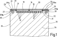
支持ストリップ10の他方の面側に、連結手段18と、織物またはプラスチックマットの形態のカバーストリップ20が配置されている。 カバーストリップ20は、支持ストリップ10の長手方向端部33に沿って所定の距離だけ幅方向にはみ出ている。 すなわち、カバーストリップ20の長手方向端部21は、支持ストリップ10の長手方向両端部に沿って形成されている。 この長手方向端部21は、射出成形型(図1では図示せず)に装備された取付用パイプ24の上側の壁部分22に載置される。 取付用パイプ24は、その断面が、係合要素12を有するファスナー部の支持ストリップ10を受け入れることが可能な射出成形型に適合する凹部28形状部分を有している。 係合要素12は、一般的には、その正面が、凹部28の底部と接触する。
【0029】
カバーストリップ20の長手方向端部21は、図1に示すように、係合要素12を有する面、すなわち、取付用パイプ24に面する側に向かって折り返されている。 折り返し線29は、いつもカバーストリップ20の長手方向に沿って伸びており、図面では、取付用パイプ24の側壁35に合致するように配置されている。 したがって、ファスナー部が、図1に示すように、取付用パイプ24上に載置されている場合には、カバーストリップ20は、二重層箇所と共に、型または凹部28の境界を画する壁部分22上に載置される。 カバーストリップ20の二重層箇所は、二つの部分領域29aと29bからなる。 この二つの部分領域は、一方を他方の上に重ねて、お互いが当接するようにし、好ましくは、一方と他方の間には粘着物がない。 この配置の仕方は、発泡物に対するシールの効果を促進する点において好都合である。 折り重ねられたカバーストリップ20の二重層箇所は、凹部28内への発泡成分の進入を妨げ、発泡プロセスにおけるリップシールとして機能する。 したがって、凹部28内に受け入れられる支持ストリップ10の係合要素12は、発泡成分を用いた場合でも、互いが接着される恐れがない。
【0030】
取付用パイプ24の壁部分22に沿って、カバーストリップ20が有する強磁性に加えて、カバーストリップ20の折り重ねられた長手方向端部21とファスナー部を、取付用パイプ24上で固定するための磁気保持装置を形成する永久磁石30または整列した永久磁石のストリップがある。 好ましくは、マット状のカバーストリップ、特に好ましくは、プラスチックの一種のポリエステルから形成されたカバーストリップ20は、カバーストリップの材料に強磁性粒子を埋設することで強磁性が付与されている。 カバーストリップとしてマットを使用することで、乗客用座席のクッションの製造時に、射出成形型に導入されたポリウレタン発泡物と良好な交差結合が実現される。 したがって、クッションでのファスナー部の良好な固着が、射出成形によって可能となる。
【図面の簡単な説明】
【図1】 ファスナー部が固定された取付用パイプの断面図である。
【図2】 ファスナー部の平面図である。
【符号の説明】
10 … 支持ストリップ
12 … 係合要素
16 … 鉄製ワイヤ
18 … 連結手段
20 … カバーストリップ
21 … 長手方向端部
22 … 壁部分
24 … 取付用パイプ
28 … 凹部
29a、29b … 部分領域
30 … 永久磁石
33 … 長手方向端部[0001]
【Technical field】
The present invention is a fastener portion comprising a support strip , an engagement element provided on one side of the support strip , and a cover strip covering the other side of the support strip , the cover strip comprising : is wider than the support strip, the longitudinal both ends of its is, about the fastener portion extending beyond the longitudinal both ends of the support strips.
[0002]
[Background]
As the fastener of this type, in general, to the engagement side or the front side of the support strip, shaft-like plurality of engaging elements integral with a region of Thickness is used. Manufacturing process of the support strip of such fasteners portion as this is described in DE 198 28 856 discloses. In this process, a thermoplastic resin, in particular, polyolefin or polyamide thermoplastic or liquid form, is introduced into the gap between the pressing tool and the molding tool. Forming tool is provided with a screen having an opening, also the engagement element is in the opening of the screen, Ru is formed by at least partially cured thermoplastic resin Empire. 1 micro fastener having a square centimeter per 200 to 400 of the engaging elements, Ru Tei thus produced. A support strip in the form of a fabric can be used instead of a mushroom-shaped engagement element. The engagement element can also be formed by a loop material integrated with a support strip in the form of a fabric. Furthermore, a pad or felt structure, can be used in place of the loop material.
[0003]
Fastener produced in this way, the automotive industry and carpets industry, it, up to the special use of all kinds of clothing and machinery are used in wide variety of applications. Fasteners can also be used in any of these areas, it is detachable, but also, it has been proven that provided excellent connection / fastening performance reliability.
[0004]
Oite seat aircraft and automobiles, these fasteners portion is used to secure the seat cover to the cushion member. In the manufacturing process of such a seat, the fastener portion is fixed to the cushion material , and then the cover material is fixed by meshing with the corresponding engagement element. Fastener portion is attached, et al is the mounting pipe that is provided on the injection mold, then the foam components to the injection mold in cross-section, preferably, by introducing the polyurethane, the fastener portion, to the foamable component Fixed. Mounting pipes used has a cross section which protrudes so as to cover the wall surface of the injection mold, that has a groove-like recess is formed at a position foamable component is introduced.
[0005]
The cover material is provided at a predetermined location in the fastener portion placed in the recess. Geometric shape of the seam and type decorated with seat aircraft and automobiles, is provided in this way.
[0006]
During the removal of foam from the injection mold, the foamable component will be entering the area of the engaging elements. To prevent loss of engaging action of the engagement element due to this, in the fastener portion which is generally used, depending on the application, and comprises a wider cover strip than the support strip, the cover strips, other face of the support strip, that is, provided on a surface engaging element is not provided, also the longitudinal ends of the cover strip extends beyond both ends of the support strip (see, for example, German patent application 199 56 No. 011.0). Longitudinal end which protrudes in such a cover strip, stand useful in forming a barrier foam. These ends rest against the mold wall of the injection mold and surround the mold to receive a support strip having engaging elements. For example, using a magnetic securing means, when securing the fastener part to the mold walls of the injection mold, protruding ends of the cover strip prevents penetration of the foaming component into the mold which receives the engaging element.
[0007]
U.S. Patent No. 4,784,890 discloses a typical fastener portion. According to the solving means disclosed therein, the longitudinal ends of the cover strip has an adhesive sealing strip. A clamp-like seal arch that functions as auxiliary sealing means is connected to the front end of the fastener portion at least on the bottom surface of the support strip by an adhesive. This auxiliary sealing means extends away from the fastening element with the engaging element. In manufacturing of the fastener portion, the sealing strip, so resulting in Tsu residue remains adhered to the support strip of the substrate, the manufacturing time is increased, also, so that the required also extra cost. By the manufacturing process, strongly connected by adhesive force, moreover, it is a reality is not always able always to ensure reliable sealing. Appropriate foaming components should be selected so as not to collapse the seal and waste the engaging element.
[0008]
German Utility Model No. 90 13 133 discloses discloses a design of the fastener portion that subjected to injection using a foam briquettes. Fastener portion which is a part of the adhesive strip is to shape the fastener strip having an engaging element which is in contact with longitudinal ends, and a central strip extending over the entire length of the adhesive strip. According to the solving means disclosed therein, one side of the fastener portion is covered with a cover foil. The end of the cover foil is connected to at least the end of the fastener portion, and a strip of magnetic plastic is secured at the longitudinal end of the adhesive strip. Cover foil requiring cost corresponding to the preparation and use, are used to protect the engaging elements of foamed components. This means that the sealing effect of the magnetic plastic strip is due to insufficient. Moreover, the cover foil is removed from the fastener portion, the engaging elements prior to action must be processed in a different number of treatment cycles.
[0009]
U.S. Patent No. 4,710,414 publication, the engaging element mounted on one surface of the support strip, discloses a fastener portion that is covered with a foil-like cover hood. Below the other face of the support strip, a cover strip sealing the protruding come foam beyond the foil cover in the transverse direction of the injection mold is provided.
[0010]
[Patent Document 1]
German Patent No. 198 28 856 [Patent Document 2]
German Patent Application No. 199 56 011.0 [Patent Document 3]
US Pat. No. 4,784,890 [Patent Document 4]
German utility model No. 90 13 133 [Patent Document 5]
US Pat. No. 4,710,414 gazette
DISCLOSURE OF THE INVENTION
The present invention has been completed in view of the above-described problems in the prior art .
[0012]
In particular, the present invention is absolutely reliable by improving the above- mentioned fastener part, reducing the adverse effects on the manufacturing cost and the environment, and adding a foam barrier effect to the longitudinal end of the cover strip. It is intended to ensure the sealing effect of.
[0013]
BEST MODE FOR CARRYING OUT THE INVENTION
That is, according to the present invention, both longitudinal ends of the cover strip is folded along a longitudinal end of the support strip, it is possible to longitudinally opposite ends of the support strip, whereby the foamable component A sealing lip is formed which exhibits a barrier effect against the foaming action of The sealing lip extends along the region having the engaging element. The sealing lip rests against the wall of the injection mold that surrounds the mold that receives the engaging element in the foaming process . This seal lip is pressed against the mold wall by a foam component introduced into the injection mold. A sealing lip of this, because a certain degree of elasticity in the folding-back portion has been granted, fits snugly in the wall region forming the sealing surface. Thus, the sealing effect of the foam barrier is so, and thus to significantly improve the sealing effect due to the solving means of the present invention. Moreover, the sealing lip, so forming a seal surface that is sealed so that extends outward, foam is, it is impossible Komu to enter the gap between the folding-back portion of the cover strip. For this reason, according to the present invention, substantial problems due to sealing effect does not occur.
[0014]
The production of the sealing lip, because it is not extra material and special materials are required, manufacturing is simplified. This has a positive impact on manufacturing costs. Extra material, in particular, it is possible to omit the material for covering the fastener material, without problems related to the processing of the cover foil, also the fastener of the present invention is the environmentally friendly issue.
[0015]
According to a preferred embodiment of the fastener of the present invention, in the folding-back portion, the longitudinal both ends of the cover strip, is subdivided into partial areas, and the surface thereof subregion superimposed is in surface contact with each other in, in slime teeth are in contact with each other. The fastener part of the present invention does not require an adhesive used for manufacturing the seal lip region. This promotes a reduction in manufacturing cost and eliminates the need for the addition of a pressure-sensitive adhesive containing a solvent, so that environmental issues are also taken into consideration .
[0016]
According to another preferred embodiment of the fastener of the present invention, the width of each of the partial regions of the longitudinal both ends of the cover strip are equal, and forms a bisecting shape, and their ends length is substantially the same as the length in the longitudinal direction both end portions of the support strip. End of the cover strip, Ru can be placed on the longitudinal end of the support strip. By doing so , the sealing lip does not move to the side of the support strip due to the invasion action of the foam.
[0017]
The cover strip has a mat, preferably a mat embedded with ferromagnetic particles , connected by a connecting means provided on the surface of the support strip without an engaging element, ie on the other side of the support strip. ing.
[0018]
Coupling means includes a layer of adhesive material.
[0019]
In order to give a certain bending resistance to the fastener part, especially when a predetermined length fastener part having a complicated three-dimensional structure is introduced into the injection mold, the introduction to the injection mold the curing member to facilitate handling of the support strip when, can be embedded in a layer of adhesive that is present between the cover strip and the support strip. Such curing member, mention may be made of iron-made wire that has been subjected to corrosion-resistant coating. Preferably, the wire can be galvanized. When using ferromagnetic curing wire by the wire, the position of the fastener portion of the injection mold can be magnetically fixed.
[0020]
The engagement element of the fastener part of the present invention can be made of a plastic material, preferably polyester.
[0021]
As the engaging element , a hook-shaped and / or mushroom-shaped fastening element can be used . Alternatively, a loop-like or pad-like engagement material can be used as the engagement element .
[0022]
【Example】
Examples of the fastener portion of the present invention will be described in detail below with reference to the drawings.
[0023]
Note that the scale of the figure is not constant.
[0024]
The fastener portion of the present invention has a
[0025]
Fastener part, per square centimeter 200 to 400 of the engaging element may be a micro-fasteners provided in the
[0026]
The
[0027]
The adhesive layer in which the
[0028]
On the other side of the
[0029]
[0030]
Along the
[Brief description of the drawings]
FIG. 1 is a cross-sectional view of a mounting pipe to which a fastener portion is fixed .
FIG. 2 is a plan view of a fastener portion .
[Explanation of symbols]
DESCRIPTION OF
Claims (10)
Applications Claiming Priority (3)
| Application Number | Priority Date | Filing Date | Title |
|---|---|---|---|
| DE10039940A DE10039940A1 (en) | 2000-08-16 | 2000-08-16 | Fastener part |
| DE10039940.1 | 2000-08-16 | ||
| PCT/EP2001/009238 WO2002013648A1 (en) | 2000-08-16 | 2001-08-10 | Fastener part |
Publications (2)
| Publication Number | Publication Date |
|---|---|
| JP2004505704A JP2004505704A (en) | 2004-02-26 |
| JP4726388B2 true JP4726388B2 (en) | 2011-07-20 |
Family
ID=7652557
Family Applications (1)
| Application Number | Title | Priority Date | Filing Date |
|---|---|---|---|
| JP2002518800A Expired - Lifetime JP4726388B2 (en) | 2000-08-16 | 2001-08-10 | Fastener part |
Country Status (8)
| Country | Link |
|---|---|
| US (2) | US6537643B1 (en) |
| EP (1) | EP1309258B1 (en) |
| JP (1) | JP4726388B2 (en) |
| AT (1) | ATE309713T1 (en) |
| DE (2) | DE10039940A1 (en) |
| DK (1) | DK1309258T3 (en) |
| ES (1) | ES2250481T3 (en) |
| WO (1) | WO2002013648A1 (en) |
Families Citing this family (22)
| Publication number | Priority date | Publication date | Assignee | Title |
|---|---|---|---|---|
| DE10039940A1 (en) * | 2000-08-16 | 2002-03-07 | Binder Gottlieb Gmbh & Co | Fastener part |
| US7022394B2 (en) * | 2001-05-04 | 2006-04-04 | Ykk Corporation | Fastener strip with discrete magnetically attractable area, and method and apparatus of making same |
| US6842950B2 (en) * | 2002-04-19 | 2005-01-18 | I{umlaut over (n)}tier Automotive Inc. | Shieldless hook and loop fastener |
| DE10307217B4 (en) * | 2003-02-20 | 2006-04-13 | Schott Ag | Door with viewing window for microwave ovens |
| DE10341151B3 (en) * | 2003-09-06 | 2004-12-16 | Gottlieb Binder Gmbh & Co. Kg | Burr fastener, to be integrated into foam padding for aircraft or vehicle seats to hold the seat covers in place, has a carrier strip with hooks covered by a wider tape bent over at the projecting side edges to take wires |
| DE10341152B3 (en) | 2003-09-06 | 2005-05-04 | Gottlieb Binder Gmbh & Co. Kg | Fastener part |
| AU2005212356B2 (en) * | 2004-02-10 | 2010-04-15 | Avery Dennison Corporation | Fastening member for a molded article |
| US7425360B2 (en) * | 2004-03-02 | 2008-09-16 | Velcro Industries B.V. | Touch fastener products |
| DE102004015321A1 (en) * | 2004-03-30 | 2005-10-20 | Binder Gottlieb Gmbh & Co Kg | Fastener part |
| DE102005015239A1 (en) | 2005-04-02 | 2006-10-19 | Gottlieb Binder Gmbh & Co. Kg | Fastening device and method for producing the same |
| US8556876B2 (en) * | 2005-06-21 | 2013-10-15 | The Procter & Gamble Company | Personal care articles of commerce comprising a magnetic member |
| JP4836650B2 (en) * | 2006-04-25 | 2011-12-14 | 東洋ゴム工業株式会社 | Cushion pad manufacturing method |
| US7648751B2 (en) | 2006-10-17 | 2010-01-19 | Velero Industries B.V. | Touch fastener products |
| US8256068B2 (en) * | 2007-11-16 | 2012-09-04 | Panduit Corp. | Microhook fastener apparatus |
| US20090276986A1 (en) * | 2008-05-12 | 2009-11-12 | Velcro Industries B.V. | Touch fastener products |
| US20090300890A1 (en) * | 2008-06-05 | 2009-12-10 | Ykk Corporation Of America | Flexible fastener strip assembly and methods of assembling the same |
| US8043541B2 (en) * | 2009-01-14 | 2011-10-25 | Ykk Corporation | Systems and methods of installing hook fastener elements in a mold assembly |
| US7998548B2 (en) * | 2009-01-19 | 2011-08-16 | Ykk Corporation | Male surface fastener member for use in a cushion body mold and manufacturing method thereof |
| US20120260401A1 (en) * | 2011-04-12 | 2012-10-18 | Darryl Moskowitz | Releasable securement device |
| WO2014060367A2 (en) | 2012-10-15 | 2014-04-24 | Velcro Industries B.V. | Double-sided fasteners |
| US9918526B2 (en) | 2015-06-17 | 2018-03-20 | Velcro BVBA | Mold-in touch fastening product |
| US9826801B2 (en) | 2015-06-17 | 2017-11-28 | Velcro BVBA | Mold-in touch fastening product |
Citations (3)
| Publication number | Priority date | Publication date | Assignee | Title |
|---|---|---|---|---|
| JPS6141406A (en) * | 1984-07-10 | 1986-02-27 | ミネソタ マイニング アンド マニユフアクチユアリング コンパニ− | Fastener assembly equipped with heat-shrinkable film cover |
| JPH0459705A (en) * | 1990-06-29 | 1992-02-26 | Sankyo Co Ltd | Wettable powder for agriculture and horticulture |
| US5766385A (en) * | 1995-12-06 | 1998-06-16 | Velcro Industries B.V. | Separable fastener having die-cut protective cover with pull tab and method of making same |
Family Cites Families (9)
| Publication number | Priority date | Publication date | Assignee | Title |
|---|---|---|---|---|
| US4784890A (en) * | 1986-06-20 | 1988-11-15 | Minnesota Mining And Manufacturing Company | Fastener assembly with peripheral temporary attachment layer |
| US4709523A (en) * | 1986-08-18 | 1987-12-01 | Owens-Corning Fiberglas Corporation | Insulation batt with press-on facing flanges |
| DE9013133U1 (en) * | 1990-09-15 | 1992-01-23 | Gottlieb Binder GmbH & Co, 7038 Holzgerlingen | Adhesive body for foaming into a foam molding |
| JPH0459705U (en) * | 1990-09-28 | 1992-05-22 | ||
| US5422156A (en) * | 1993-04-23 | 1995-06-06 | Aplix, Inc. | Fastening member with ferromagnetic attachment strip |
| US5945193A (en) * | 1995-12-06 | 1999-08-31 | Velcro Industries B.V. | Touch fastener with porous metal containing layer |
| DE19828856C1 (en) * | 1998-06-29 | 1999-10-07 | Binder Gottlieb Gmbh & Co | Process to mold a holding stud on a thermoplastic tab for baby nappies |
| DE19956011A1 (en) * | 1999-11-20 | 2001-06-21 | Binder Gottlieb Gmbh & Co | Fastener part |
| DE10039940A1 (en) * | 2000-08-16 | 2002-03-07 | Binder Gottlieb Gmbh & Co | Fastener part |
-
2000
- 2000-08-16 DE DE10039940A patent/DE10039940A1/en not_active Withdrawn
- 2000-10-13 US US09/689,766 patent/US6537643B1/en not_active Expired - Lifetime
-
2001
- 2001-08-10 ES ES01974155T patent/ES2250481T3/en not_active Expired - Lifetime
- 2001-08-10 WO PCT/EP2001/009238 patent/WO2002013648A1/en active IP Right Grant
- 2001-08-10 AT AT01974155T patent/ATE309713T1/en active
- 2001-08-10 EP EP01974155A patent/EP1309258B1/en not_active Expired - Lifetime
- 2001-08-10 DE DE50108101T patent/DE50108101D1/en not_active Expired - Lifetime
- 2001-08-10 US US10/312,781 patent/US20030099811A1/en not_active Abandoned
- 2001-08-10 DK DK01974155T patent/DK1309258T3/en active
- 2001-08-10 JP JP2002518800A patent/JP4726388B2/en not_active Expired - Lifetime
Patent Citations (3)
| Publication number | Priority date | Publication date | Assignee | Title |
|---|---|---|---|---|
| JPS6141406A (en) * | 1984-07-10 | 1986-02-27 | ミネソタ マイニング アンド マニユフアクチユアリング コンパニ− | Fastener assembly equipped with heat-shrinkable film cover |
| JPH0459705A (en) * | 1990-06-29 | 1992-02-26 | Sankyo Co Ltd | Wettable powder for agriculture and horticulture |
| US5766385A (en) * | 1995-12-06 | 1998-06-16 | Velcro Industries B.V. | Separable fastener having die-cut protective cover with pull tab and method of making same |
Also Published As
| Publication number | Publication date |
|---|---|
| JP2004505704A (en) | 2004-02-26 |
| ES2250481T3 (en) | 2006-04-16 |
| WO2002013648A1 (en) | 2002-02-21 |
| ATE309713T1 (en) | 2005-12-15 |
| DE10039940A1 (en) | 2002-03-07 |
| DK1309258T3 (en) | 2006-04-03 |
| EP1309258B1 (en) | 2005-11-16 |
| EP1309258A1 (en) | 2003-05-14 |
| US20030099811A1 (en) | 2003-05-29 |
| US6537643B1 (en) | 2003-03-25 |
| DE50108101D1 (en) | 2005-12-22 |
Similar Documents
| Publication | Publication Date | Title |
|---|---|---|
| JP4726388B2 (en) | Fastener part | |
| JP4769245B2 (en) | Hook fastener parts | |
| KR100685334B1 (en) | Component for overcasting for a moulded object and manufacturing process thereof | |
| EP0921739B1 (en) | Separable fastener having a perimeter cover gasket | |
| US7927681B2 (en) | Fastening assembly and cushion having fastening assembly | |
| KR101255623B1 (en) | Fastening tape for seat pad and seat pad having the same | |
| TWI538633B (en) | Forming method of forming flat buckle and cushioning body | |
| US20140375105A1 (en) | Vehicle seat and method of manufacturing the same | |
| KR101828745B1 (en) | Fastener tape | |
| JP2002522252A (en) | Method for producing foam, especially foam cushion members for vehicle seats | |
| US6468371B1 (en) | Method for producing a moulded part, especially a sheet member for a car or plane passenger seat | |
| JP2001190311A (en) | Fastening member and its attaching method to integrally foam-molded article | |
| JPS6315983A (en) | Seat | |
| CN105620329A (en) | Seat cushion assembly structure and vehicle seats | |
| JPH0314428Y2 (en) | ||
| US7429415B2 (en) | Adhesive closing part | |
| KR20160081393A (en) | Mold for molding foam pad | |
| WO2023184091A1 (en) | Buckle belt and manufacturing method for buckle belt | |
| US7563499B2 (en) | Adhesive closing part | |
| JP2007075591A (en) | Seat pad for vehicle | |
| KR101410212B1 (en) | Fastener Tape | |
| JP3644546B2 (en) | Molded surface fastener body | |
| JPS5845141Y2 (en) | Mounting structure of instrument panel pads in automobiles | |
| WO2024084575A1 (en) | Clip and clip connector | |
| JPH0437483Y2 (en) |
Legal Events
| Date | Code | Title | Description |
|---|---|---|---|
| A621 | Written request for application examination |
Free format text: JAPANESE INTERMEDIATE CODE: A621 Effective date: 20071022 |
|
| A131 | Notification of reasons for refusal |
Free format text: JAPANESE INTERMEDIATE CODE: A131 Effective date: 20100706 |
|
| A601 | Written request for extension of time |
Free format text: JAPANESE INTERMEDIATE CODE: A601 Effective date: 20101005 |
|
| A602 | Written permission of extension of time |
Free format text: JAPANESE INTERMEDIATE CODE: A602 Effective date: 20101013 |
|
| A521 | Request for written amendment filed |
Free format text: JAPANESE INTERMEDIATE CODE: A523 Effective date: 20101227 |
|
| TRDD | Decision of grant or rejection written | ||
| A01 | Written decision to grant a patent or to grant a registration (utility model) |
Free format text: JAPANESE INTERMEDIATE CODE: A01 Effective date: 20110322 |
|
| A61 | First payment of annual fees (during grant procedure) |
Free format text: JAPANESE INTERMEDIATE CODE: A61 Effective date: 20110412 |
|
| R150 | Certificate of patent or registration of utility model |
Ref document number: 4726388 Country of ref document: JP Free format text: JAPANESE INTERMEDIATE CODE: R150 Free format text: JAPANESE INTERMEDIATE CODE: R150 |
|
| FPAY | Renewal fee payment (event date is renewal date of database) |
Free format text: PAYMENT UNTIL: 20140422 Year of fee payment: 3 |
|
| R250 | Receipt of annual fees |
Free format text: JAPANESE INTERMEDIATE CODE: R250 |
|
| R250 | Receipt of annual fees |
Free format text: JAPANESE INTERMEDIATE CODE: R250 |
|
| R250 | Receipt of annual fees |
Free format text: JAPANESE INTERMEDIATE CODE: R250 |
|
| R250 | Receipt of annual fees |
Free format text: JAPANESE INTERMEDIATE CODE: R250 |
|
| R250 | Receipt of annual fees |
Free format text: JAPANESE INTERMEDIATE CODE: R250 |
|
| R250 | Receipt of annual fees |
Free format text: JAPANESE INTERMEDIATE CODE: R250 |
|
| R250 | Receipt of annual fees |
Free format text: JAPANESE INTERMEDIATE CODE: R250 |
|
| R250 | Receipt of annual fees |
Free format text: JAPANESE INTERMEDIATE CODE: R250 |
|
| EXPY | Cancellation because of completion of term |