JP4726191B2 - Position / orientation correction apparatus, position / orientation correction method, program thereof, and storage medium - Google Patents
Position / orientation correction apparatus, position / orientation correction method, program thereof, and storage medium Download PDFInfo
- Publication number
- JP4726191B2 JP4726191B2 JP2005029828A JP2005029828A JP4726191B2 JP 4726191 B2 JP4726191 B2 JP 4726191B2 JP 2005029828 A JP2005029828 A JP 2005029828A JP 2005029828 A JP2005029828 A JP 2005029828A JP 4726191 B2 JP4726191 B2 JP 4726191B2
- Authority
- JP
- Japan
- Prior art keywords
- correction
- parameter
- orientation
- parameters
- value
- Prior art date
- Legal status (The legal status is an assumption and is not a legal conclusion. Google has not performed a legal analysis and makes no representation as to the accuracy of the status listed.)
- Expired - Fee Related
Links
- 238000012937 correction Methods 0.000 title claims description 269
- 238000000034 method Methods 0.000 title claims description 125
- 238000005259 measurement Methods 0.000 claims description 264
- 238000003384 imaging method Methods 0.000 claims description 159
- 238000004364 calculation method Methods 0.000 claims description 122
- 238000001514 detection method Methods 0.000 claims description 85
- 230000008569 process Effects 0.000 claims description 67
- 230000036544 posture Effects 0.000 claims description 42
- 238000012545 processing Methods 0.000 description 46
- 230000006870 function Effects 0.000 description 25
- 239000013598 vector Substances 0.000 description 23
- 239000011159 matrix material Substances 0.000 description 17
- 238000004422 calculation algorithm Methods 0.000 description 8
- 238000012986 modification Methods 0.000 description 8
- 230000004048 modification Effects 0.000 description 8
- 230000004069 differentiation Effects 0.000 description 5
- 238000013519 translation Methods 0.000 description 5
- 238000007796 conventional method Methods 0.000 description 4
- 238000010586 diagram Methods 0.000 description 4
- 238000006243 chemical reaction Methods 0.000 description 3
- 238000002945 steepest descent method Methods 0.000 description 3
- 238000012935 Averaging Methods 0.000 description 2
- 230000008859 change Effects 0.000 description 2
- 230000000694 effects Effects 0.000 description 2
- 238000000605 extraction Methods 0.000 description 2
- 239000003550 marker Substances 0.000 description 2
- 238000000691 measurement method Methods 0.000 description 2
- 230000000007 visual effect Effects 0.000 description 2
- 238000009825 accumulation Methods 0.000 description 1
- 238000013459 approach Methods 0.000 description 1
- 230000003190 augmentative effect Effects 0.000 description 1
- 239000003086 colorant Substances 0.000 description 1
- 238000004590 computer program Methods 0.000 description 1
- 239000000470 constituent Substances 0.000 description 1
- 239000006185 dispersion Substances 0.000 description 1
- 238000011156 evaluation Methods 0.000 description 1
- 230000005484 gravity Effects 0.000 description 1
- 230000001771 impaired effect Effects 0.000 description 1
- 238000002372 labelling Methods 0.000 description 1
- 239000004973 liquid crystal related substance Substances 0.000 description 1
- 239000000203 mixture Substances 0.000 description 1
- 238000011160 research Methods 0.000 description 1
- 238000007619 statistical method Methods 0.000 description 1
- 230000009466 transformation Effects 0.000 description 1
Images


Description
本発明は、物体の位置及び姿勢、特に撮像装置の位置及び姿勢を計測する方法及び装置に関するものである。 The present invention relates to a method and apparatus for measuring the position and orientation of an object, particularly the position and orientation of an imaging apparatus.
近年、現実空間と仮想空間の繋ぎ目のない結合を目的とした、複合現実感に関する研究が盛んに行われている。複合現実感の提示を行う画像表示装置は、ビデオカメラなどの撮像装置によって撮影された現実空間の画像に、撮像装置の位置及び姿勢に応じて生成した仮想空間の画像(たとえばコンピュータ・グラフィックスにより描画された仮想物体や文字情報など)を重畳描画した画像を表示する装置として実現することができる。 In recent years, research on mixed reality has been actively conducted for the purpose of seamless connection between the real space and the virtual space. An image display device that presents a mixed reality is a virtual space image (for example, by computer graphics) that is generated according to the position and orientation of an imaging device on a real space image captured by an imaging device such as a video camera. It can be realized as a device that displays an image in which a drawn virtual object, character information, etc.) are superimposed and drawn.
このような画像表示装置を実現するには、現実空間中に定義した基準座標系(重畳しようとする仮想物体の位置及び姿勢を決定する基準となる現実空間中の座標系)と、撮像装置の座標系(カメラ座標系)との間の、相対的な位置及び姿勢を計測することが不可欠である。これは、仮想物体(仮想空間画像)を現実空間上の位置に合わせて描画するには、基準座標系に対する撮像装置の現実のカメラパラメータと同一のカメラパラメータを用いて仮想物体の画像を生成しなければならないからである。例えば、現実の室内のある位置に仮想物体を重畳表示する場合には、部屋に基準座標系を定義し、その基準座標系における撮像装置の位置及び姿勢を求めればよい。また、観察者が手に保持する現実の箱に何らかの仮想の模様やラベルを重畳表示する場合には、箱自身の物体座標系を基準座標系と考え、撮像装置に対する箱(基準座標系)の位置及び姿勢を求めればよい。 In order to realize such an image display device, a reference coordinate system defined in the real space (a coordinate system in the real space serving as a reference for determining the position and orientation of the virtual object to be superimposed) It is essential to measure the relative position and orientation with respect to the coordinate system (camera coordinate system). In order to draw a virtual object (virtual space image) according to a position in the real space, an image of the virtual object is generated using the same camera parameters as the real camera parameters of the imaging device with respect to the reference coordinate system. Because it must be. For example, when a virtual object is superimposed and displayed at a position in an actual room, a reference coordinate system is defined in the room, and the position and orientation of the imaging device in the reference coordinate system may be obtained. In addition, when a virtual pattern or label is superimposed and displayed on an actual box held by an observer, the object coordinate system of the box itself is considered as a reference coordinate system, and the box (reference coordinate system) of the image pickup apparatus is considered. What is necessary is just to obtain | require a position and attitude | position.
撮像装置の位置及び姿勢を計測する方法として、現実空間中に複数の指標(人為的なマーカや自然特徴など)を配置あるいは設定し、撮像装置によって撮像された画像内における指標の投影像の座標を検出して、指標の座標情報との関係に基づいて撮像装置の位置及び姿勢を求めることが一般的に行われている(例えば、非特許文献1)。しかし、このアプローチを用いる場合、常に指標が撮像されなくてはならないという制約がある。 As a method for measuring the position and orientation of the imaging device, a plurality of indices (artificial markers, natural features, etc.) are arranged or set in the real space, and the coordinates of the projected image of the indices in the image captured by the imaging device In general, the position and orientation of the imaging device are obtained based on the relationship with the coordinate information of the index (for example, Non-Patent Document 1). However, when using this approach, there is a restriction that the index must always be imaged.
一方、撮像装置に磁気センサや超音波センサなどを用いた6自由度位置姿勢センサを装着し、これによって計測した撮像装置の位置及び姿勢の誤差を、指標を撮像した画像を用いて得られる情報(画像情報)によって補正する試みがなされている(例えば、特許文献1,特許文献2)。特許文献2で開示されている方法では、撮像画像中に指標が検出された場合にはその情報に基づいてセンサ計測値の誤差が補正され、指標が検出されない場合には6自由位置姿勢センサの計測値がそのまま撮像装置の位置及び姿勢として使用される。指標の検出の有無に関わらずに撮像装置の位置及び姿勢が得られるため、複合現実感の提示を安定して行うことができる。
On the other hand, a 6-DOF position / orientation sensor using a magnetic sensor, an ultrasonic sensor, or the like is attached to the image pickup device, and the information obtained by using the image obtained by imaging the index of the position and orientation error of the image pickup device measured thereby. Attempts to correct by (image information) have been made (for example,
また、特許文献2の方法では、検出された指標の数が3点以上の場合には、撮像装置の位置及び姿勢の6自由度が画像情報に基づいて算出され、検出された指標の数が2点及び1点の場合には、センサによって計測された撮像装置の位置あるいは姿勢のいずれか(2または3自由度)のみを補正する処理が適用される。すなわち、検出された指標の数を判定基準として、撮像装置の位置及び姿勢の算出に利用するアルゴリズムを切り替えることが行われている。これにより、画像情報のみからでは撮像装置の位置及び姿勢を求められない場合(撮像された指標の数が3点に満たない場合)であっても、センサ計測値を基準としながら、その誤差を極力打ち消すような補正のなされた位置及び姿勢を取得することができる。
In the method of
一方、特許文献1の方法では、検出された指標の数に関わらず、センサによって計測された撮像装置の位置あるいは姿勢のいずれかのみを画像情報に基づいて補正する処理が適用される。この補正方法では、姿勢を補正する場合には、検出された指標毎に指標上における誤差を打ち消すような回転補正値を個別に求め、それらを平均化することで姿勢計測値に対する補正値が算出される。また、位置を補正する場合には、検出された指標毎に指標上における誤差を打ち消すような平行移動補正値を個別に求め、それらを平均化することで位置計測値に対する補正値が算出される。指標の数に関わらず補正の自由度を2または3に限定するため、情報量が不十分な場合であっても安定した解を得ることができる。
On the other hand, in the method of
上記特許文献2の手法では、指標が3点以上観測されている際には必ず、位置及び姿勢の6自由度を画像情報から求めるアルゴリズムが選択される。しかし実際には、画像上の一部の領域に指標が偏在して観測されている場合のように、指標の数が3点以上であっても、位置及び姿勢の6自由度を安定して求めるのに十分な画像情報が入力画像中に含まれていない状況が存在する。特許文献2の手法は、このような状況下において、得られる解の精度や安定性が不十分となることがあった。
In the method of the above-mentioned
一方、上記特許文献1の手法は、精度よりも安定性を重視した手法であり、画像上の一部の領域に指標が偏在して観測されている場合のような画像情報が不十分な状況下であっても、特許文献2の手法と比較して安定した計測を行うことができる。しかし、十分な画像情報が得られている場合でも一部のパラメータの補正のみしか行わないので、画像情報を最大限に生かした精度を得ることができなかった。
On the other hand, the method of
また、上記特許文献1の手法では、個々の指標に対する2次元的な補正値の平均を求めているだけであるので、全指標上での誤差の和を最小とするような最適な補正を行うことができなかった。
Further, since the method of
本発明はこのような従来技術の問題点に鑑みてなされたものであり、計測対象物体の位置及び姿勢の計測を、安定性と精度とを両立しながら行うことが可能な位置姿勢測定方法及び装置を提供することを目的とする。 The present invention has been made in view of such problems of the prior art, and a position and orientation measurement method capable of measuring the position and orientation of a measurement target object while achieving both stability and accuracy, and An object is to provide an apparatus.
上述の目的は、撮像装置の位置姿勢を構成する複数のパラメータの1つ以上を補正する位置姿勢補正装置であって、複数のパラメータを入力する位置姿勢入力手段と、現実空間に複数配置された指標を撮像装置で撮像した画像を入力する画像入力手段と、画像から指標の画像座標の実測値を検出する検出手段と、検出手段による検出結果に基づいて、複数のパラメータのうち何れを補正対象とするか決定する決定手段と、複数のパラメータおよび実測値に基づいて、複数のパラメータのうち、決定手段によって補正対象のパラメータと決定されなかったパラメータを補正せず、補正対象のパラメータと決定されたパラメータを補正する補正手段と、を有し、補正手段が、指標の座標と複数のパラメータとに基づいて、指標の画像座標の理論値を算出する理論値算出手段と、実測値と理論値との誤差を小さくするように、補正対象と決定されたパラメータの補正値を算出する補正値算出手段と、補正値に基づいて、複数のパラメータのうち補正対象のパラメータと決定されなかったパラメータを補正せず、補正対象のパラメータと決定されたパラメータを補正するパラメータ補正手段と、を有することを特徴とする位置姿勢補正装置によって達成される。 The above-described object is a position / orientation correction apparatus that corrects one or more of a plurality of parameters constituting the position / orientation of the imaging apparatus, and a plurality of position / orientation input means for inputting a plurality of parameters and a plurality of parameters are arranged in the real space. An image input unit that inputs an image obtained by imaging an index with an imaging device, a detection unit that detects an actual measurement value of the image coordinates of the index from the image, and which of a plurality of parameters is to be corrected based on a detection result by the detection unit Based on the plurality of parameters and the actual measurement values, the parameter to be corrected is determined as the parameter to be corrected without correcting the parameter that has not been determined as the parameter to be corrected by the determining unit. Correction means for correcting the parameters, the correction means based on the index coordinates and a plurality of parameters, the theoretical value of the index image coordinates A theoretical value calculating means for calculating, a correction value calculating means for calculating a correction value of a parameter determined as a correction target so as to reduce an error between the actual measurement value and the theoretical value, and a plurality of parameters based on the correction value This is achieved by a position / orientation correction apparatus comprising: a parameter to be corrected and a parameter correction unit that corrects the determined parameter without correcting the parameter to be corrected and the parameter that has not been determined .
また、上述の目的は、計測対象物体の位置姿勢を構成する複数のパラメータを補正する位置姿勢補正装置であって、複数のパラメータを入力する位置姿勢入力手段と、計測対象物体に複数配置された指標を撮像装置で撮像した画像を入力する画像入力手段と、撮像画像から指標の画像座標の実測値を検出する検出手段と、検出手段による検出結果に基づいて、複数のパラメータのうち何れを補正対象とするか決定する決定手段と、複数のパラメータおよび実測値に基づいて、複数のパラメータのうち決定手段によって補正対象のパラメータと決定されなかったパラメータを補正せず、補正対象のパラメータと決定されたパラメータを補正する補正手段と、を有し、補正手段が、複数のパラメータに基づいて、指標の画像座標の理論値を算出する理論値算出手段と、実測値と理論値との誤差を小さくするように、補正対象のパラメータと決定されたパラメータの補正値を算出する補正値算出手段と、補正値に基づいて、複数のパラメータのうち補正対象のパラメータと決定されなかったパラメータを補正せず、補正対象のパラメータと決定されたパラメータを補正するパラメータ補正手段と、を有することを特徴とする位置姿勢補正装置によっても達成される。 The above-described object is a position / orientation correction apparatus that corrects a plurality of parameters constituting the position / orientation of a measurement target object, and is provided with a plurality of position / orientation input means for inputting a plurality of parameters and a plurality of measurement target objects. An image input unit that inputs an image obtained by imaging an index with an imaging device, a detection unit that detects an actual measurement value of the index image from the captured image, and which of a plurality of parameters is corrected based on a detection result by the detection unit Based on a plurality of parameters and actual measurement values, a determination unit that determines whether to be a target, a parameter that has not been determined as a correction target parameter by the determination unit, is determined as a correction target parameter without correcting the parameter. Correction means for correcting the parameter, and the correction means calculates a theoretical value of the image coordinate of the index based on the plurality of parameters. A theoretical value calculating means, a correction value calculating means for calculating a correction value of the parameter to be corrected and the determined parameter so as to reduce an error between the actually measured value and the theoretical value, and a plurality of parameters based on the correction value And a parameter correction unit that corrects the parameter to be corrected and the determined parameter without correcting the parameter to be corrected and the parameter that has not been determined. .
また、上述の目的は、撮像装置の位置姿勢を構成する複数のパラメータを補正する位置姿勢補正装置であって、複数のパラメータを入力する位置姿勢入力手段と、現実空間に複数配置され、位置が既知である指標を、撮像装置で撮像した画像を入力する画像入力手段と、画像から指標の画像座標の実測値を検出する検出手段と、検出手段による検出結果に基づいて、複数のパラメータのうち何れを補正対象とするか決定する決定手段と、複数のパラメータおよび実測値に基づいて、複数のパラメータのうち決定手段によって補正対象のパラメータと決定されなかったパラメータを補正せず、補正対象のパラメータと決定されたパラメータを補正する補正手段と、を有し、補正手段が、指標の位置と複数のパラメータとに基づいて、指標の画像座標の理論値を算出する理論値算出手段と、実測値と理論値との誤差を小さくするように、補正対象のパラメータと決定されたパラメータの補正値を算出する補正値算出手段と、補正値に基づいて、複数のパラメータのうち補正対象のパラメータと決定されなかったパラメータを補正せず、補正対象のパラメータと決定されたパラメータを補正するパラメータ補正手段と、を有し、複数のパラメータは、位置を示す3つの位置成分および姿勢を示す3つの姿勢成分の6成分に相当するパラメータであって、決定手段が、検出手段で検出された指標が1つである場合に、複数のパラメータのうち2成分以下に相当するパラメータを補正対象のパラメータとして決定し、検出手段で検出された指標が2つである場合に、検出された指標の画像座標間の距離に基づいて、複数のパラメータのうち3成分以下に相当するパラメータを補正対象のパラメータとして決定し、検出手段で検出された指標が3つ以上である場合に、検出された指標の画像座標から得られる領域の面積に基づいて、複数のパラメータのうち6成分以下に相当するパラメータを補正対象のパラメータとして決定することを特徴とする位置姿勢補正装置によっても達成される。 The above-described object is a position / orientation correction apparatus that corrects a plurality of parameters constituting the position / orientation of the imaging apparatus, and a plurality of position / orientation input means for inputting a plurality of parameters are arranged in the real space, and the positions are Based on the detection result of the detection means by the image input means for inputting the image captured by the imaging device, the image input means for inputting a known index, the actual value of the image coordinates of the index from the image, and a plurality of parameters Based on a plurality of parameters and actual measurement values, a determination unit that determines which one is to be corrected, and a parameter that is not determined as a correction target parameter by the determination unit among the plurality of parameters is not corrected. A correction unit that corrects the determined parameter, and the correction unit is configured to display the index image based on the position of the index and the plurality of parameters. A theoretical value calculating means for calculating the theoretical value of the standard, a correction value calculating means for calculating the correction value of the parameter to be corrected and the determined parameter so as to reduce an error between the actually measured value and the theoretical value, and a correction value A correction target parameter and a parameter correction unit that corrects the determined parameter without correcting the correction target parameter among the plurality of parameters, and the plurality of parameters, Parameters corresponding to six components of three position components indicating positions and three posture components indicating postures, and when the determining means has one index detected by the detecting means, among the plurality of parameters When the parameters corresponding to two or less components are determined as parameters to be corrected, and there are two indices detected by the detection means, the image coordinates of the detected indices Based on the distance, a parameter corresponding to three or less components among a plurality of parameters is determined as a correction target parameter, and when there are three or more indices detected by the detection means, the image coordinates of the detected indices The position / orientation correction apparatus is characterized in that a parameter corresponding to six or less components among a plurality of parameters is determined as a correction target parameter based on the area of the region obtained from the above.
また、上述の目的は、計測対象物体の位置姿勢を構成する複数のパラメータを補正する位置姿勢補正装置であって、複数のパラメータを入力する位置姿勢入力手段と、計測対象物体に複数配置された指標を撮像装置で撮像した画像を入力する画像入力手段と、撮像画像から指標の画像座標の実測値を検出する検出手段と、検出手段による検出結果に基づいて、複数のパラメータのうち何れを補正対象とするか決定する決定手段と、複数のパラメータおよび実測値に基づいて、複数のパラメータのうち決定手段によって補正対象のパラメータと決定されなかったパラメータを補正せず、補正対象のパラメータと決定されたパラメータを補正する補正手段と、を有し、補正手段が、複数のパラメータに基づいて、指標の画像座標の理論値を算出する理論値算出手段と、実測値と理論値との誤差を小さくするように、補正対象のパラメータと決定されたパラメータの補正値を算出する補正値算出手段と、補正値に基づいて、複数のパラメータのうち補正対象のパラメータと決定されなかったパラメータを補正せず、補正対象のパラメータと決定されたパラメータを補正するパラメータ補正手段と、を有し、複数のパラメータは、位置を示す3つの位置成分および姿勢を示す3つの姿勢成分の6成分に相当するパラメータであって、決定手段が、検出手段で検出された指標が1つである場合に、複数のパラメータのうち2成分以下に相当するパラメータを補正対象のパラメータとして決定し、検出手段で検出された指標が2つである場合に、検出された指標の画像座標間の距離に基づいて、複数のパラメータのうち3成分以下に相当するパラメータを補正対象のパラメータとして決定し、検出手段で検出された指標が3つ以上である場合に、検出された指標の画像座標から得られる領域の面積に基づいて、複数のパラメータのうち6成分以下に相当するパラメータを補正対象のパラメータとして決定することを特徴とする位置姿勢補正装置によっても達成される。 The above-described object is a position / orientation correction apparatus that corrects a plurality of parameters constituting the position / orientation of a measurement target object, and is provided with a plurality of position / orientation input means for inputting a plurality of parameters and a plurality of measurement target objects. An image input unit that inputs an image obtained by imaging an index with an imaging device, a detection unit that detects an actual measurement value of the index image from the captured image, and which of a plurality of parameters is corrected based on a detection result by the detection unit Based on a plurality of parameters and actual measurement values, a determination unit that determines whether to be a target, a parameter that has not been determined as a correction target parameter by the determination unit, is determined as a correction target parameter without correcting the parameter. Correction means for correcting the parameter, and the correction means calculates a theoretical value of the image coordinate of the index based on the plurality of parameters. A theoretical value calculating means, a correction value calculating means for calculating a correction value of the parameter to be corrected and the determined parameter so as to reduce an error between the actually measured value and the theoretical value, and a plurality of parameters based on the correction value A correction target parameter and parameter correction means for correcting the determined parameter without correcting the correction target parameter and the parameter that has not been determined, and the plurality of parameters include three position components indicating the position. And a parameter corresponding to six components of the three posture components indicating the posture, and when the determination unit has one index detected by the detection unit, a parameter corresponding to two or less components among the plurality of parameters Is determined as a parameter to be corrected, and when there are two indices detected by the detection means, based on the distance between the image coordinates of the detected indices, When a parameter corresponding to three or less components among the number of parameters is determined as a parameter to be corrected, and there are three or more indices detected by the detection means, the area of the region obtained from the image coordinates of the detected indices This is achieved by a position and orientation correction apparatus characterized in that a parameter corresponding to six or less components among a plurality of parameters is determined as a correction target parameter .
本発明に係る位置姿勢計測装置によれば、指標の画像座標の理論値と実測値との誤差を最小とする補正値を求め、この補正値によってセンサの計測値を補正することで、従来の方法と比べて安定性と精度に優れた計測が実現できる。 According to the position and orientation measurement apparatus according to the present invention, a correction value that minimizes the error between the theoretical value and the actual measurement value of the image coordinate of the index is obtained, and the measurement value of the sensor is corrected by this correction value. Compared to the method, measurement with superior stability and accuracy can be realized.
以下添付図面を参照して、本発明を好適な実施形態に従って詳細に説明する。
[第1の実施形態]
本実施形態に係る位置姿勢計測装置は、撮像装置と計測対象物体の位置及び姿勢の計測を行う。以下、本実施形態に係る位置姿勢計測装置及び位置姿勢計測方法について説明する。
Hereinafter, the present invention will be described in detail according to preferred embodiments with reference to the accompanying drawings.
[First Embodiment]
The position / orientation measurement apparatus according to the present embodiment measures the positions and orientations of the imaging apparatus and the measurement target object. Hereinafter, the position and orientation measurement apparatus and the position and orientation measurement method according to the present embodiment will be described.
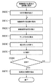
図1は、本実施形態における位置姿勢計測装置の構成を示している。同図に示したように、本実施形態における位置姿勢計測装置100は、画像入力部160、指標検出部110、センサ計測値入力部150、及び位置姿勢算出部120によって構成される。そして、撮像装置130及び、撮像装置130と計測対象物体170に取り付けられた位置姿勢センサ140(140a,140b)に接続されている。
FIG. 1 shows a configuration of a position / orientation measurement apparatus according to the present embodiment. As shown in the figure, the position /
計測対象物体170上の複数の位置には、物体座標系(計測対象物体170上に定義される座標系)における位置が既知である複数個の指標Qk(k=1,2,・・・,K)が配置されている。図1の例は、K=9、すなわち9個の指標Q1〜Q9が配置されている状況を示している。指標Qkは、例えば、それぞれが異なる色を有する同一形状(図では円形)のマーカによって構成してもよいし、それぞれが異なるテクスチャ特徴を有する自然特徴等の特徴点によって構成してもよい。また、ある程度の面積を有する四角形の単色領域によって形成されるような、四角形指標を用いることも可能である。撮影画像上における投影像の画像座標が検出可能であって、かついずれの指標であるかが何らかの方法で識別可能であるような指標であれば、何れの形態であってもよい。また指標は故意に設定されたものであっても良いし、故意に設定されたものではない、自然形状のものを用いても良い。
The plurality of positions on the
例えばビデオカメラである撮像装置130が出力する画像(以下、これを撮影画像と呼ぶ)は、位置姿勢計測装置100に入力される。
For example, an image output from the
6自由度センサである位置姿勢センサ140a及び140bは、それぞれ撮像装置130及び計測対象物体170に装着されており、基準座標系における撮像装置130及び計測対象物体170の位置及び姿勢を計測する。位置姿勢センサ140が出力する計測値は、位置姿勢計測装置100に入力される。位置姿勢センサ140は、例えば、米国Polhemus社のFASTRAK等によって構成される。なお、位置姿勢センサ140によって計測される位置及び姿勢は、磁場の歪み等の影響によって誤差を含んだものとなっている。
Position and
画像入力部160は、位置姿勢装置100へ入力される撮影画像をデジタルデータに変換し、指標検出部110へと出力する。
The
センサ計測値入力部150は、位置姿勢センサ140(140a,140b)から夫々の計測値を入力し、位置姿勢算出部120へと出力する。
The sensor measurement
指標検出部110は、画像入力部160より撮影画像を入力し、入力した画像中に撮影されている指標Qkの画像座標を検出する。例えば、指標Qkの各々が異なる色を有するマーカによって構成されている場合には、撮影画像上から各々のマーカ色に対応する領域を検出し、その重心位置を指標の検出座標とする。また、指標Qkの各々が異なるテクスチャ特徴を有する特徴点によって構成されている場合には、既知の情報として予め保持している各々の指標のテンプレート画像によるテンプレートマッチングを撮影画像上に施すことにより、指標の位置を検出する。また、四角形指標を用いる場合は、画像に2値化処理を施した後にラベリングを行い、4つの直線によって形成されている領域を指標候補として検出する。さらに、候補領域の中に特定のパターンがあるか否かを判定することによって誤検出を排除し、また、指標の識別子を取得する。なお、このようにして検出される四角形指標は、本明細書では、4つの頂点の個々によって形成される4つの指標であると考える。
指標検出部110は、さらに、検出された各々の指標Qknの画像座標uQknとその識別子knを位置姿勢算出部120へと出力する。ここで、n(n=1,,,N)は検出された指標夫々に対するインデックスであり、Nは検出された指標の総数を表している。
位置姿勢算出部120は、センサ計測値入力部150の出力である撮像装置130及び計測対象物体170の位置及び姿勢の計測値と、指標検出部110の出力である各々の指標Qknの画像座標uQknを入力し、入力した情報に基づいて、計測対象物体170あるいは撮像装置130の位置及び姿勢の計測値の誤差を補正し、補正後の位置及び姿勢のデータを出力する。
The position /
なお、図1に示した画像入力部160、指標検出部110、センサ計測値入力部150、及び位置姿勢算出部120の少なくとも一部は、独立した装置として実現しても良いし、夫々1つもしくは複数のコンピュータにインストールし、コンピュータのCPUにより実行することで、その機能を実現するソフトウェアとして実現しても良い。本実施形態では、各部(画像入力部160、指標検出部110、センサ計測値入力部150、及び位置姿勢算出部120)は、それぞれソフトウェアにより実現され、同一のコンピュータにインストールされているものとする。
Note that at least a part of the
図2は、画像入力部160、指標検出部110、センサ計測値入力部150、及び位置姿勢算出部120の夫々の機能を、ソフトウェアを実行することで実現するためのコンピュータの基本構成を示す図である。
FIG. 2 is a diagram illustrating a basic configuration of a computer for realizing the functions of the
CPU1001は、RAM1002やROM1003に格納されたプログラムやデータを用いてコンピュータ全体の制御を行うと共に、画像入力部160、指標検出部110、センサ計測値入力部150、及び位置姿勢算出部120の夫々のソフトウェアの実行を制御して、各部の機能を実現する。
The
RAM1002は、外部記憶装置1007や記憶媒体ドライブ1008からロードされたプログラムやデータを一時的に記憶するエリアを備えると共に、CPU1001が各種の処理を行うために必要とするワークエリアを備える。
The
ROM1003は、一般にコンピュータのプログラムや設定データなどが格納されている。キーボード1004、マウス1005は入力デバイスであり、操作者はこれらを用いて、各種の指示をCPU1001に入力することができる。
The
表示部1006は、CRTや液晶ディスプレイなどにより構成されており、例えば、位置姿勢計測のために表示すべきメッセージ等を表示することができる。
The
外部記憶装置1007は、ハードディスクドライブなどの大容量情報記憶装置として機能する装置であって、ここにOS(オペレーティングシステム)やCPU1001が実行するプログラム等を保存する。また本実施形態の説明において、既知であると説明する情報はここに保存されており、必要に応じてRAM1002にロードされる。
The
記憶媒体ドライブ1008は、CD−ROMやDVD−ROMなどの記憶媒体に記憶されているプログラムやデータをCPU1001からの指示に従って読み出して、RAM1002や外部記憶装置1007に出力する。
The
I/F1009は、撮像装置130を接続するためのアナログビデオポートあるいはIEEE1394等のデジタル入出力ポート、位置姿勢センサ140を接続するためのRS232CあるいはUSB等のシリアルポート、また、算出した位置及び姿勢を外部へ出力するためのイーサネット(登録商標)ポート等によって構成される。夫々が入力したデータはI/F1009を介してRAM1002に取り込まれる。画像入力部160及びセンサ計測値入力部150の機能の一部は、I/F1009によって実現される。
上述した各構成要素は、バス1010によって相互に接続される。
The I /
The above-described components are connected to each other by a
図3は、位置姿勢算出部120の処理手順を示すフローチャートであり、本実施形態ではCPU1001が位置姿勢算出部120の機能を実現するプログラムを実行することにより実現される。なお、以下の処理を行う前段で、同フローチャートに従ったプログラムコードは、例えば外部記憶装置1007からRAM1002に既にロードされているものとする。
FIG. 3 is a flowchart showing a processing procedure of the position /
ステップS3000において、位置姿勢算出部120は、検出された各々の指標Qknの画像座標uQknとその識別子knを指標抽出部110から入力する。なお、各指標の物体座標系における3次元座標xO Qknは、既知の値としてRAM1002に予めロードされているものとする。
In step S3000, the position and
ステップS3005において、位置姿勢算出部120は、撮像装置130及び計測対象物体170の位置及び姿勢のセンサによる計測値をセンサ計測値入力部150から入力する。
In step S <b> 3005, the position /
ステップS3010において、位置姿勢算出部120は、指標が検出されているか否かを判定する。指標が検出されていない場合はステップS3080に処理を進め、それ以外の場合はステップS3020に処理を進める。
In step S3010, the position /
ステップS3020において、位置姿勢算出部120は、検出された指標の総数が一つか否かを判定する.指標の総数が一つの場合はステップS3025に処理を進め、それ以外の場合はステップS3030に処理を進める。
In step S3020, the position /
ステップS3025において、位置姿勢算出部120は、ステップS3005で得た撮像装置130の姿勢の計測値のうちのパン及びチルト角に対して、検出されている指標上での誤差(物体座標系における指標の3次元座標xO Qknと撮像装置130及び計測対象物体170の位置及び姿勢の計測値から導出する投影座標の理論値uQkn*と、実際の検出座標uQknとの誤差)を打ち消すような補正を加え、ステップS3080に処理を進める。ステップS3025における補正処理としては、周知の処理を適用することが可能であるため、これ以上の説明は行わない。具体的には、例えば特許文献1(ランドマーク1点を利用したカメラの回転による補正方法(段落「0019」〜「0029」)およびランドマークを複数点利用したカメラの回転による補正方法(段落「0039」〜「0050」))に開示されている方法を用いることができる。
In step S3025, the position /
ステップS3030において、位置姿勢算出部120は、検出された指標の総数が二つか否かを判定する.指標の総数が二つの場合はステップS3033に処理を進め、それ以外の場合はステップS3040に処理を進める。
In step S3030, the position /
ステップS3033において、位置姿勢算出部120は、検出された二つの指標の画像上での距離を算出し、その値と所定の値として定められている閾値T1(例えば、画像の対角線長の1/4)との比較を行う。距離が閾値T1以上の場合にはステップS3035に処理を進め、それ以外の場合はステップS3025に処理を進め、上述した処理を行う。
In step S <b> 3033, the position /
ステップS3035において、位置姿勢算出部120は、ステップS3005で得た計測対象物体170の位置及び姿勢の計測値と、撮像装置130の位置の計測値を固定値として、撮像装置130の姿勢の計測値を表す3パラメータ(パン,チルト及びロール角)に対して、検出されている全指標上での誤差の和を最小とするような補正を加え、ステップS3080に処理を進める。この処理工程の詳細は後述する。
In step S3035, the position /
ステップS3040において、位置姿勢算出部120は、検出された全指標(このステップが実行されるのは、検出された指標の総数が三つ以上の場合のみである)の画像座標を包含する凸包を算出する。画像上の点群に対する凸包の算出方法は画像処理の基本的事項として広く公知のものであるので、その詳細な説明は省略する。
In step S3040, the position /
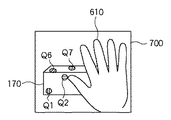
図6,図7,及び図8は、撮像装置130によって計測対象物体170を撮影することで取得される撮影画像の一例を示している。図6に示す撮影画像600上では指標Q1,Q5,Q6,Q9が、図7の撮影画像700上では指標Q1,Q2,Q6,Q7が,図8の撮影画像800上では指標Q2,Q6,Q7が観測されており、それ以外の指標は、他の物体(本実施形態においてはユーザの手610)によって隠蔽されているものとする。
6, 7, and 8 illustrate an example of a captured image acquired by capturing the
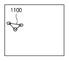
これらの撮影画像に対して指標の検出を行い、図3のフローチャートで示した位置姿勢算出部120の処理ステップを実行すると、各画像において検出される指標の数は3以上であるので、ステップS3040以降の処理が実行されることになる。図9,図10及び図11は、それぞれ撮影画像600,700,800に対してステップS3040の処理を実行した際に得られる、検出指標の成す凸包(900,1000,1100)を示している。なお、以下では、各凸包の面積をそれぞれA900,A1000,及びA1100と表記したときに、以下に述べる閾値T2及び閾値T3に対して、A1100<T2<A1000<T3<A900という関係が満たされているものとする。
When indices are detected for these captured images and the processing steps of the position /
ステップS3050において、位置姿勢算出部120は、ステップS3040で算出した凸包の面積と、所定の値として定められている閾値T2(例えば、撮影画像全体の面積の1/16)との比較を行う。面積が閾値T2以上の場合はステップS3060に処理を進め、それ以外の場合はステップS3025へと処理を進める。図6〜図11の例では、撮影画像800についてはステップS3025へ、撮影画像700及び600についてはステップS3060へと処理が進行する。
In step S3050, the position /
ステップS3060において、位置姿勢算出部120は、ステップS3040で算出した凸包の面積と、所定の値として定められている閾値T3(例えば、撮影画像全体の面積の1/9)との比較を行う。面積が閾値T3以上の場合はステップS3070に処理を進め、それ以外の場合はステップS3035へと処理を進める。図6〜図11の例では、撮影画像700についてはステップS3035へ、撮影画像600についてはステップS3070へと処理が進行する。
In step S <b> 3060, the position /
ステップS3070において、位置姿勢算出部120は、検出されている全指標上での誤差の和を最小とするような撮像装置130の位置と姿勢を算出する。この処理工程の詳細は後述する。
In step S3070, the position /
ステップS3080において、位置姿勢算出部120は、ステップS3025、S3035及びS3070で得られた撮像装置130及び計測対象物体170の位置及び姿勢を表すデータを、I/F1009を介して外部へと出力する。あるいは、これらのデータを、他のアプリケーションから利用可能な状態としてRAM1002上に格納する。
In step S3080, the position /
なお、ステップS3025,S3035,S3070の各工程では、撮像装置130に関する計測値のみに補正を加えているので、ステップS3080で出力される位置及び姿勢のデータは、計測対象物体170に関しては、ステップS3005で入力したセンサによる計測値そのものとなる。しかし、位置及び姿勢の出力形態はこれに限られるものではなく、逆に、撮像装置130の位置及び姿勢の計測値には補正を加えずにセンサによる計測値をそのまま出力し、計測対象物体170の位置及び姿勢の計測値に補正を加えて出力しても良い。この場合は、ステップS3080において、以下に述べる座標変換処理を行った後に、変換後の位置及び姿勢を出力する。
In each of the steps S3025, S3035, and S3070, only the measurement value related to the
同次座標系を用いた4×4の座標変換行列によって位置及び姿勢を表記すると、計測対象物体170の補正後の位置及び姿勢MWOは、センサ計測値として得られた撮像装置130の位置及び姿勢M# WC(以下、# はセンサによる計測値を表す記号)と、センサ計測値として得られた計測対象物体170の位置及び姿勢M# WOと、ステップS3070までの処理結果として得られた撮像装置130の補正後の位置及び姿勢MWCに基づいて、次式によって算出される。
When the position and orientation are expressed by a 4 × 4 coordinate transformation matrix using a homogeneous coordinate system, the corrected position and orientation M WO of the
![]()
![]()
このとき、撮像装置130によって定義されるカメラ座標系における計測対象物体170の位置及び姿勢は、
At this time, the position and orientation of the
![]()
![]()
となる。すなわち、ステップS3070までの処理結果として得られた撮像装置130の補正後の位置及び姿勢(MWC)と、センサ計測値として得られた計測対象物体170の位置及び姿勢(M# WO)とを出力する場合と、センサ計測値として得られた撮像装置130の位置及び姿勢(M# WC)と、式1によって求められる計測対象物体170の補正後の位置及び姿勢(MWO)とを出力する場合では、計測対象物体170と撮像装置130の相対的な位置及び姿勢の関係は等価となる。したがって、本装置の出力を利用するアプリケーションが要求する形態に合わせて、出力形態を選択できるようになっていることが好ましい。
It becomes. That is, the corrected position and orientation (M WC ) of the
また、カメラ座標系における計測対象物体170の位置及び姿勢(MCO)を式2から算出してこれを出力しても良いし、物体座標系における撮像装置130の位置及び姿勢(MCO -1)を求めて、これを出力してもよい。
Further, the position and orientation (M CO ) of the
ステップS3090において、位置姿勢算出部120は、処理を終了するか否かの判定を行い、処理を終了しない場合には、ステップS3000へと処理を進める。
以上によって、撮像装置の位置及び姿勢が計測される。
In step S3090, the position /
As described above, the position and orientation of the imaging apparatus are measured.
次に、図4のフローチャートを用いて、上記ステップS3035における撮像装置130の姿勢算出の処理工程を説明する。以下では、算出すべき未知パラメータである撮像装置130の姿勢を、3値ベクトル
s = ωWC = [ξWC ψWC ζWC]T
によって内部的に表現している。
Next, the processing steps for calculating the posture of the
s = ω WC = [ξ WC ψ WC ζ WC ] T
Is expressed internally.
姿勢を3値によって表現する方法には様々なものが存在するが、ここでは、ベクトルの大きさによって回転角を、ベクトルの向きによって回転軸方向を定義するような3値のベクトルによって表現されているものとする。なお、姿勢ωは、次式、 There are various methods for expressing the posture by ternary values, but here, the rotation angle is expressed by the magnitude of the vector, and the ternary vector is defined by defining the rotation axis direction by the vector direction. It shall be. The posture ω is expressed by the following equation:

によって、3×3の回転行列Rによっても表現可能であり、ωとRとは、互いに一意に変換することができる。Rからωへの変換方法は公知であるので、その詳細な説明は省略する。 Can also be represented by a 3 × 3 rotation matrix R, and ω and R can be uniquely converted from each other. Since the conversion method from R to ω is known, the detailed description thereof is omitted.
ステップS4000において、位置姿勢算出部120は、センサ計測値として得られた撮像装置130の姿勢を、sの初期値とする。
In step S4000, the position /
ステップS4010において、位置姿勢算出部120は、各々の指標Qknに対して、その画像座標の推定値uQkn*を算出する。uQkn*の算出は、sによって定義される指標の観測方程式、すなわち、指標Qkn各々の物体座標系における座標xO Qkn(既知な情報として予め保持している)から画像座標を算出する関数:
In step S4010, the position and
に基づいて行われる。具体的には、観測方程式Fc()は、xO Qknとsから当該指標のカメラ座標(撮像装置130の視点位置を原点として定義し、更に互いに直交する3軸を夫々X軸、Y軸、Z軸として定義した座標系)xC Qknを求める次式、
Based on. Specifically, the observation equation Fc () is defined from x O Qkn and s as camera coordinates of the index (the viewpoint position of the
及び、カメラ座標xC Qknから画像座標uQkn*を求める次式、 And the following equation for obtaining the image coordinates u Qkn * from the camera coordinates x C Qkn :
によって構成されている。ここでtWC及びtWOは、撮像装置130と計測対象物体170の夫々の位置計測値(平行移動成分)を表す3次元ベクトルであり、ここでは固定値として取り扱われる。また、RWOは計測対象物体170の姿勢計測値(回転成分)を表す3×3の回転行列であり、同様に固定値として取り扱われる。また、fC x及びfC yは、それぞれx軸方向及びy軸方向における撮像装置130の焦点距離であり、既知の値として予め保持されているものとする。
It is constituted by. Here, t WC and t WO are three-dimensional vectors representing the position measurement values (parallel movement components) of the
ステップS4020において、位置姿勢算出部120は、各々の指標Qknに対して、画像座標の推定値uQkn*と実測値uQknとの誤差ΔuQknを、次式によって算出する。
In step S4020, the position /
ステップS4030において、位置姿勢算出部120は、各々の指標Qknに対して、sに関する画像ヤコビアン(すなわち、式4の観測方程式Fc()をsの各要素で偏微分した解を各要素に持つ2行×3列のヤコビ行列)Jus Qkn(=∂u/∂s)を算出する。具体的には、式6の右辺をカメラ座標xC Qknの各要素で偏微分した解を各要素に持つ2行×3列のヤコビ行列Jux Qkn(=∂u/∂x)と、式5の右辺をベクトルsの各要素で偏微分した解を各要素に持つ3行×3列のヤコビ行列Jxs Qkn(=∂x/∂s)を算出し、次式によってJus Qknを算出する。
In step S4030, the position /
ステップS4040において、位置姿勢算出部120は、ステップS4020及びステップS4030において算出した誤差ΔuQkn及び画像ヤコビアンJus Qknに基づいて、sの補正値Δsを算出する。具体的には、誤差ΔuQknを垂直に並べた2N次元の誤差ベクトル
In step S4040, the position /
及び、画像ヤコビアンJus Qknを垂直に並べた2N行×3列の行列 And a matrix of 2N rows × 3 columns in which the image Jacobian J us Qkn are arranged vertically
を作成し、Θの擬似逆行列Θ+を用いて、 And using the pseudo inverse matrix Θ + of Θ,
として算出する。このように、本実施形態では補正値Δsを、最急降下法を用いて算出している。 Calculate as Thus, in this embodiment, the correction value Δs is calculated using the steepest descent method.
ステップS4050において、位置姿勢算出部120は、ステップS4040において算出した補正値Δsを用いて式12に従ってsを補正し、得られた値をsの新たな推定値とする。
In step S4050, the position /
ステップS4060において、位置姿勢算出部120は、誤差ベクトルUが予め定めた閾値より小さいかどうか、あるいは、補正値Δsが予め定めた閾値より小さいかどうかといった何らかの判定基準を用いて、計算が収束しているか否かの判定を行う。収束してない場合には、補正後のsを用いて、再度ステップS4010以降の処理を行う。一方、収束していると判断した場合には、ステップS4070へと処理を進める。
In step S4060, the position /
ステップS4070において、位置姿勢算出部120は、ステップS4060までの処理によって得られたsを、撮像装置130の姿勢の(補正後の)推定値 ωWCとする。
In step S4070, the position /
以上によって、センサ計測値として得られた位置パラメータを固定して、全指標上での誤差の和を最小化するような姿勢パラメータを求めることができる。 As described above, the position parameter obtained as the sensor measurement value is fixed, and the posture parameter that minimizes the sum of errors on all the indices can be obtained.
次に、図5のフローチャートを用いて、上記ステップS3070における撮像装置130の位置及び姿勢算出の処理工程を説明する。以下では、算出すべき未知パラメータである撮像装置130の位置及び姿勢を、6値ベクトルs = [tWC T ωWC T]T = [xWC yWC zWC ξWC ψWC ζWC]Tによって内部的に表現している。
Next, the processing steps for calculating the position and orientation of the
ステップS5000において、位置姿勢算出部120は、センサ計測値として得られた撮像装置130の位置及び姿勢を、sの初期値とする。
In step S5000, the position /
ステップS5010において、位置姿勢算出部120は、各々の指標Qknに対して、その画像座標の推定値uQkn*を算出する。uQkn*の算出は、sによって定義される指標の観測方程式、すなわち、各指標Qknの物体座標系における座標xO Qknから画像座標を算出する関数:
In step S5010, the position and
に基づいて行われる。具体的には、観測方程式F’c()は、xO Qknとsから当該指標のカメラ座標xC Qknを求める式5、及び、カメラ座標xC Qknから画像座標uQkn*を求める式6によって構成されている。ただしここでは、式5におけるtWC(撮像装置130の位置を表す)を、固定値としてではなく、sを構成するパラメータの一部として取り扱う。一方、計測対象物体170の位置tWO及び姿勢RWOに関しては、センサによる計測値をそのまま固定値として使用する。
Based on. Specifically, the observation equation F′c () is an expression 5 for obtaining the camera coordinates x C Qkn of the index from x O Qkn and s, and an expression 6 for obtaining the image coordinates u Qkn * from the camera coordinates x C Qkn. It is constituted by. However, t WC (representing the position of the imaging device 130) in Equation 5 is treated as a part of parameters constituting s, not as a fixed value. On the other hand, with respect to the position t WO and orientation R WO of the
ステップS5020において、位置姿勢算出部120は、各々の指標Qknに対して、画像座標の推定値uQkn*と実測値uQknとの誤差ΔuQknを、式7によって算出する。
In step S5020, the position /
ステップS5030において、位置姿勢算出部120は、各々の指標Qknに対して、sに関する画像ヤコビアン(すなわち、式13の観測方程式F’c()をsの各要素で偏微分した解を各要素に持つ2行×6列のヤコビ行列)Jus Qkn(=∂u/∂s)を算出する。具体的には、式6の右辺をカメラ座標xC Qknの各要素で偏微分した解を各要素に持つ2行×3列のヤコビ行列Jux Qkn(=∂u/∂x)と、式5の右辺をベクトルsの各要素で偏微分した解を各要素に持つ3行×6列のヤコビ行列Jxs Qkn(=∂x/∂s)を算出し、式8によってJus Qknを算出する。
In step S5030, the position /
ステップS5040において、位置姿勢算出部120は、ステップS5020及びステップS5030において算出した誤差ΔuQkn及び画像ヤコビアンJus Qknに基づいて、sの補正値Δsを算出する。具体的には、誤差ΔuQknを垂直に並べた2N次元の誤差ベクトルU及び、画像ヤコビアンJus Qknを垂直に並べた2N行×6列の行列Θを作成し、Θの擬似逆行列Θ+を用いて、式11によって算出する。
In step S5040, the position /
ステップS5050において、位置姿勢算出部120は、ステップS5040において算出した補正値Δsを用いて式12に従ってsを補正し、得られた値をsの新たな推定値とする。
In step S5050, the position /
ステップS5060において、位置姿勢算出部120は、誤差ベクトルUが予め定めた閾値より小さいかどうか、あるいは、補正値Δsが予め定めた閾値より小さいかどうかといった何らかの判定基準を用いて、計算が収束しているか否かの判定を行う。収束していない場合には、補正後のsを用いて、再度ステップS5010以降の処理を行う。一方、収束していると判定された場合には、ステップS5070へと処理を進める。
In step S5060, the position /
ステップS5070において、位置姿勢算出部120は、ステップS5060までの処理によって得られたsを、撮像装置130の補正後の位置及び姿勢の推定値とする。
In step S5070, the position /
なお、本実施形態では、ステップS3070の処理において、撮像装置130の位置及び姿勢を補正の対象としていたが、計測対象物体170の位置及び姿勢を補正の対象として処理を行っても良い。この場合は、算出すべき未知パラメータを、計測対象物体170の位置及び姿勢を表す6値ベクトルs = [tWO T ωWO T]T = [xWO yWO zWO ξWO ψWO ζWO]Tによって内部的に表現し、センサ計測値として得られた計測対象物体170の位置及び姿勢をsの初期値とする。また、観測方程式F’c()を構成する式5を、次式のように変形する。
In the present embodiment, in the process of step S3070, the position and orientation of the
![]()
![]()
このとき、撮像装置130の位置tWC及び姿勢RWCに関しては、センサによる計測値をそのまま固定値として使用する。
At this time, with respect to the position t WC and the posture R WC of the
また、カメラ座標系における計測対象物体170の位置及び姿勢や、物体座標系における撮像装置130の位置及び姿勢を未知のパラメータとして求めても良い。
Further, the position and orientation of the
前者の場合、算出すべき未知パラメータを、カメラ座標系における計測対象物体170の位置及び姿勢を表す6値ベクトルs = [tCO T ωCO T]T = [xCO yCO zCO ξCO ψCO ζCO]Tによって内部的に表現する。また、カメラ座標系における計測対象物体170の位置及び姿勢(M# CO)を、次式、
In the former case, the unknown parameters to be calculated, 6 values representing the position and orientation of the
![]()
![]()
によってセンサ計測値(M# WC及びM# WO)に基づいて求め、これをsの初期値とする。また、観測方程式F’c()を構成する式5を、次式のように変形する。 Based on the sensor measurement values (M # WC and M # WO ), this is used as the initial value of s. Further, Equation 5 constituting the observation equation F′c () is transformed as the following equation.
一方、後者の場合は、算出すべき未知パラメータを、物体座標系における撮像装置130の位置及び姿勢を表す6値ベクトルs = [tOC T ωOC T]T = [xOC yOC zOC ξOC ψOC ζOC]Tによって内部的に表現する。また、物体座標系における撮像装置130の位置及び姿勢(M# CO)を、次式、
On the other hand, in the latter case, an unknown parameter to be calculated is a six-value vector s = [t OC T ω OC T ] T = [x OC y OC z OC ξ] representing the position and orientation of the
![]()
![]()
によってセンサ計測値(M# WC及びM# WO)に基づいて求め、これをsの初期値とする。また、観測方程式F’c()を構成する式5を、次式のように変形する。 Based on the sensor measurement values (M # WC and M # WO ), this is used as the initial value of s. Further, Equation 5 constituting the observation equation F′c () is transformed as the following equation.
以上のようにして、計測対象物体170と撮像装置130との間の相対的な位置及び姿勢の関係を未知のパラメータとして、センサによる位置及び姿勢計測値の誤差を補正することができる。
As described above, it is possible to correct the error of the position and orientation measurement values obtained by the sensor using the relative position and orientation relationship between the
従来の位置姿勢計測装置では、指標の分布を考慮していないため、画像上の一部の領域に指標が偏在して観測されている場合に解が不安定になる。一方、本実施形態に係る位置姿勢計測装置によれば、ステップS3033や、ステップS3040,S3050,S3060によって指標の分布範囲の大きさを考慮した手法の選択が行われるため、例えば検出された指標の数が多くても、それらが画像上の小領域に偏在しているような場合に、位置及び姿勢の6自由度を安定して求めるのに不十分であるという判定を行うことができる。そのため、画像上の一部の領域に指標が偏在して観測されている場合であっても適切な位置姿勢推定手法が選択され、不安定な解が得られる状況に陥る可能性が低下し、従来手法と比して安定した解を得ることができる。 In the conventional position and orientation measurement apparatus, since the distribution of the index is not taken into consideration, the solution becomes unstable when the index is unevenly observed in a part of the area on the image. On the other hand, according to the position / orientation measurement apparatus according to the present embodiment, since the method considering the size of the index distribution range is selected in step S3033 or steps S3040, S3050, and S3060, for example, the detected index Even if the number is large, when they are unevenly distributed in a small area on the image, it can be determined that it is insufficient to stably obtain the 6 degrees of freedom of the position and orientation. Therefore, even if the index is unevenly distributed in some areas on the image, the appropriate position and orientation estimation method is selected, and the possibility of falling into an unstable solution situation is reduced, A stable solution can be obtained as compared with the conventional method.
また、本実施形態に係る位置姿勢計測装置によれば、撮像装置の位置及び姿勢を構成する一部のパラメータのみを選択してセンサ計測値の補正を行う場合に、その制約の中で指標上での誤差の和を最小化するような補正を行うことができる。したがって、未知とするパラメータを減らすことによって撮像装置の位置及び姿勢の計測を安定化させようとする場合であっても、従来と比べて高精度な計測を行うことができる。 Further, according to the position / orientation measurement apparatus according to the present embodiment, when only some parameters constituting the position and orientation of the imaging apparatus are selected to correct the sensor measurement value, It is possible to perform correction so as to minimize the sum of errors. Therefore, even when it is intended to stabilize the measurement of the position and orientation of the imaging apparatus by reducing the unknown parameters, it is possible to perform measurement with higher accuracy than in the past.
[第2の実施形態]
本実施形態に係る位置姿勢計測装置は、室内等に設定された基準座標系における任意の計測対象物体の位置及び姿勢の計測を行う。
[Second Embodiment]
The position and orientation measurement apparatus according to the present embodiment measures the position and orientation of an arbitrary measurement target object in a reference coordinate system set in a room or the like.
本実施形態に係る位置姿勢計測装置は、撮像装置に位置姿勢センサが取り付けられておらず、三脚等によって既知の位置及び姿勢に固定して設置されていることが、第1の実施形態とは異なっている。以下では、第1の実施形態との相違点のみを説明する。 The position / orientation measurement apparatus according to the present embodiment has a position / orientation sensor attached to the imaging apparatus, and is fixedly installed at a known position and attitude using a tripod or the like. Is different. Only the differences from the first embodiment will be described below.
図12は、本実施形態における位置姿勢計測装置の構成を示している。同図に示したように、本実施形態における位置姿勢計測装置1200は、画像入力部160、指標検出部110、センサ計測値入力部150、及び位置姿勢算出部1220によって構成されており、撮像装置130及び位置姿勢センサ140に接続されている。
FIG. 12 shows the configuration of the position / orientation measurement apparatus according to this embodiment. As shown in the figure, the position /
撮像装置130は、三脚1280によって、空間中の既知の位置、姿勢に固定して設置されている。撮像装置130が出力する撮影画像は、位置姿勢計測装置1200の画像入力部160に入力される。基準座標系における撮像装置130の位置及び姿勢は、既知の値として予め保持されているものとする。
The
センサ計測値入力部150は、計測対象物体170の位置及び姿勢の計測値を位置姿勢センサ140から入力し、位置姿勢算出部1220へと出力する。
The sensor measurement
位置姿勢算出部1220は、センサ計測値入力部150の出力である計測対象物体170の位置及び姿勢の計測値と、指標検出部110の出力である各々の指標Qknの画像座標uQknを入力し、入力した情報に基づいて、計測対象物体170の位置及び姿勢の計測値の誤差を補正し、補正後の位置及び姿勢のデータを出力する。
The position /
なお、図12に示した画像入力部160、指標検出部110、センサ計測値入力部150、及び位置姿勢算出部1220の少なくとも一部は、独立した装置として実現しても良いし、夫々1つもしくは複数のコンピュータにインストールし、コンピュータのCPUにより実行することで、その機能を実現するソフトウェアとして実現しても良い。本実施形態では、各部(画像入力部160、指標検出部110、センサ計測値入力部150、及び位置姿勢算出部1220)は、それぞれソフトウェアにより実現され、同一のコンピュータにインストールされているものとする。ソフトウェアを実行することで、各部の機能を実現するためのコンピュータの基本構成は、第1の実施形態と同様であるので説明を省略する。
Note that at least a part of the
本実施形態における位置姿勢算出部1220の処理手順は、第1の実施形態における位置姿勢算出部120の処理手順(図3のフローチャートに対応)とほぼ同一である。唯一の違いは、撮像装置130の位置及び姿勢が、計測値として与えられるのではなく、既知の値として予め保持されていることである。位置姿勢算出部1220は、撮像装置130の位置及び姿勢の既知の値を、撮像装置130の位置及び姿勢の仮の計測値とおき、第1の実施形態におけるステップS3000からステップS3070までと同一の工程によって撮像装置130の位置及び姿勢の計測値の補正を行い、この補正結果に基づいて、ステップS3080において、第1の実施形態と同様に計測対象物体170の位置及び姿勢の計測値を補正する(式1)。本実施形態では、位置姿勢算出部1220がステップS3080において出力するのは、計測対象物体170の位置及び姿勢のみである。
The processing procedure of the position /
以上によって、計測対象物体の位置及び姿勢が計測される。このように、本実施形態に係る位置姿勢計測装置によっても、指標の分布範囲の大きさを考慮した手法の選択が行われるため、画像上の一部の領域に指標が偏在して観測されている場合であっても適切な位置姿勢推定手法が選択され、従来手法と比して安定した解を得ることができる。 As described above, the position and orientation of the measurement object are measured. As described above, the position / orientation measurement apparatus according to the present embodiment also selects a method in consideration of the size of the distribution range of the index, and therefore, the index is unevenly observed in a partial region on the image. Even in such a case, an appropriate position and orientation estimation method is selected, and a stable solution can be obtained as compared with the conventional method.
[第3の実施形態]
本実施形態に係る位置姿勢計測装置は、室内等の空間中における撮像装置の位置及び姿勢の計測を行う。以下、本実施形態に係る位置姿勢計測装置について説明する。
[Third Embodiment]
The position / orientation measurement apparatus according to the present embodiment measures the position and orientation of an imaging apparatus in a space such as a room. The position / orientation measurement apparatus according to this embodiment will be described below.
本実施形態においては撮像装置以外の計測対象物体は存在せず、本実施形態に係る位置姿勢計測装置は、撮像装置の位置及び姿勢の計測のみを行うことが、第1の実施形態とは異なっている。以下では、第1の実施形態との相違点のみを説明する。 Unlike the first embodiment, there is no measurement target object other than the imaging device in the present embodiment, and the position / orientation measurement device according to the present embodiment only measures the position and orientation of the imaging device. ing. Only the differences from the first embodiment will be described below.
図13は、本実施形態における位置姿勢計測装置の構成を示している。同図に示したように、本実施形態における位置姿勢計測装置1300は、画像入力部160、指標検出部110、センサ計測値入力部150、及び位置姿勢算出部1320によって構成されており、撮像装置130及び位置姿勢センサ140に接続されている。
FIG. 13 shows the configuration of the position / orientation measurement apparatus according to this embodiment. As shown in the figure, the position /
また、現実空間中の複数の位置には、撮像装置130によって撮影するための指標として、基準座標系における位置が既知である複数個の指標Qkが配置されている。指標Qkは、第1の実施形態と同様に、撮影画像上における投影像の画像座標が検出可能であって、かついずれの指標であるかが何らかの方法で識別可能であるような指標であれば、どのような形態であってもよい。
In addition, a plurality of indices Q k whose positions in the reference coordinate system are known are disposed at a plurality of positions in the real space as indices for photographing by the
センサ計測値入力部150は、撮像装置130の位置及び姿勢の計測値を位置姿勢センサ140から入力し、位置姿勢算出部1320へと出力する。
The sensor measurement
位置姿勢算出部1320は、センサ計測値入力部150の出力である撮像装置130の位置及び姿勢の計測値と、指標検出部110の出力である各々の指標Qknの画像座標uQknを入力し、入力した情報に基づいて、撮像装置130の位置及び姿勢の計測値の誤差を補正し、補正後の位置及び姿勢のデータを出力する。
The position /
なお、図13に示した画像入力部160、指標検出部110、センサ計測値入力部150、及び位置姿勢算出部1320の少なくとも一部は、独立した装置として実現しても良いし、夫々1つもしくは複数のコンピュータにインストールし、コンピュータのCPUにより実行することで、その機能を実現するソフトウェアとして実現しても良い。本実施形態では、各部(画像入力部160、指標検出部110、センサ計測値入力部150、及び位置姿勢算出部1320)は、それぞれソフトウェアにより実現され、同一のコンピュータにインストールされているものとする。ソフトウェアを実行することで、各部の機能を実現するためのコンピュータの基本構成は、第1の実施形態と同様であるので説明を省略する。
Note that at least a part of the
本実施形態における位置姿勢算出部1320の処理手順は、第1の実施形態における位置姿勢算出部120の処理手順(図3のフローチャートに対応)と類似しているため、図3を参照しながら、第1の実施形態との相違点のみについて説明する。
The processing procedure of the position /
ステップS3005において、位置姿勢算出部1320は、センサによって計測された撮像装置130の位置及び姿勢を、センサ計測値入力部150から入力する。
In step S3005, the position /
ステップS3025において、位置姿勢算出部1320は、ステップS3005で得た撮像装置130の姿勢計測値のうちのパン及びチルト角に対して、検出されている指標上での誤差(基準座標系における指標の3次元座標xW Qknと撮像装置130の位置及び姿勢の計測値から導出する投影座標の理論値uQkn*と、実際の検出座標uQknとの誤差)を打ち消すような補正を加え、ステップS3080に処理を進める。
In step S3025, the position /
このような補正処理としては、周知の方法を用いることができるため、これ以上の説明は行わない。具体的には、例えば特許文献1(ランドマーク1点を利用したカメラの回転による補正方法(段落「0019」〜「0029」)およびランドマークを複数点利用したカメラの回転による補正方法(段落「0039」〜「0050」))に開示されている方法を用いることができる。 As such correction processing, since a known method can be used, no further explanation will be given. Specifically, for example, Patent Document 1 (a correction method by rotation of a camera using one landmark (paragraphs “0019” to “0029”) and a correction method by rotation of a camera using a plurality of landmarks (paragraph “ 0039 "-" 0050 "))) can be used.
ステップS3035において、位置姿勢算出部1320は、ステップS3005で得た撮像装置130の位置計測値を固定値として、撮像装置130の姿勢計測値を表す3パラメータ(パン,チルト及びロール角)に対して、検出されている全指標上での誤差の和を最小とするような補正を加え、ステップS3080に処理を進める。この補正処理工程は、第1の実施形態におけるステップS3035の補正処理工程(図4のフローチャートに対応)と類似したものとなる。ただし、本実施形態の場合、指標の観測方程式F’’c()が、基準座標系における指標Qknの座標xW Qkn(既知な情報として予め保持している)から画像座標を算出する関数となる。すなわち、観測方程式F’’c()は次式によって表される。
In step S3035, the position /
具体的には、観測方程式F’’c()は、xW Qknとsから当該指標のカメラ座標xC Qknを求める次式、 Specifically, the observation equation F ″ c () is expressed by the following equation for obtaining the camera coordinates x C Qkn of the index from x W Qkn and s:
及び、カメラ座標xC Qknから画像座標uQkn*を求める式6によって構成されており、この点のみが異なっている。ここでtWCは、撮像装置130の位置計測値を表す3次元ベクトルであり、ここでは固定値として取り扱われる。
And is constituted by a camera coordinate x C Qkn by Equation 6 for obtaining the image coordinates u Qkn *, only this point is different. Here, t WC is a three-dimensional vector representing the position measurement value of the
ステップS3070において、位置姿勢算出部1320は、検出されている全指標上での誤差の和を最小とするような撮像装置130の位置と姿勢を算出する。この処理工程での具体的な処理は、例えば特許文献2に開示されているような周知技術を用いて実現することが可能であるので、ここでの説明は省略する。
In step S3070, the position /
ステップS3080において、位置姿勢算出部1320は、ステップS3070までの結果として得られた撮像装置130の位置及び姿勢を、I/F1009を介して外部へと出力する。あるいは、このデータを、他のアプリケーションから利用可能な状態としてRAM1002上に格納する。
In step S3080, the position /
以上によって、撮像装置の位置及び姿勢が計測される。このように、本実施形態に係る位置姿勢計測装置によっても、指標の分布範囲の大きさを考慮した手法の選択が行われるため、画像上の一部の領域に指標が偏在して観測されている場合であっても適切な位置姿勢推定手法が選択され、従来手法と比して安定した解を得ることができる。 As described above, the position and orientation of the imaging apparatus are measured. As described above, the position / orientation measurement apparatus according to the present embodiment also selects a method in consideration of the size of the distribution range of the index, and therefore, the index is unevenly observed in a partial region on the image. Even in such a case, an appropriate position and orientation estimation method is selected, and a stable solution can be obtained as compared with the conventional method.
[第4の実施形態]
本実施形態に係る位置姿勢計測装置は、室内等の空間中における任意の計測対象物体の位置及び姿勢の計測を行う。以下、本実施形態に係る位置姿勢計測装置について説明する。本実施形態においては、撮像装置ではなく、任意の計測対象物体の位置及び姿勢を計測することが、第3の実施形態と異なっている。以下では、第3の実施形態との相違点のみを説明する。
[Fourth Embodiment]
The position and orientation measurement apparatus according to the present embodiment measures the position and orientation of an arbitrary measurement target object in a space such as a room. The position / orientation measurement apparatus according to this embodiment will be described below. In the present embodiment, it is different from the third embodiment in that the position and orientation of an arbitrary measurement target object, not an imaging device, are measured. Only the differences from the third embodiment will be described below.
図14は、本実施形態における位置姿勢計測装置の構成を示している。同図に示したように、本実施形態における位置姿勢計測装置1400は、画像入力部160、指標検出部110、センサ計測値入力部150、撮像部1430、位置姿勢計測部1440、及び位置姿勢算出部1420によって構成されており、計測対象物体1470に接続されている。
FIG. 14 shows the configuration of the position / orientation measurement apparatus according to this embodiment. As shown in the figure, the position /
撮像部1430は、位置及び姿勢を計測したい対象である計測対象物体1470に固定して取り付けられており、指標を含む現実空間の映像を撮影する。
The
位置姿勢計測部1440は、撮像部1430に固定して装着されており、基準座標系における撮像部1430の位置及び姿勢を計測してセンサ計測値入力部150へと出力する。位置姿勢計測部1440は、例えば、米国Polhemus社のFASTRAK等によって構成される。
The position /
画像入力部160は、撮像部1430が撮影した撮影画像をデジタルデータに変換し、指標検出部110へと出力する。
The
センサ計測値入力部150は、撮像部1430の位置及び姿勢の計測値を位置姿勢計測部1440から入力し、位置姿勢算出部1420へと出力する。
The sensor measurement
位置姿勢算出部1420は、センサ計測値入力部150の出力である撮像部1430の位置及び姿勢の計測値と、指標検出部110の出力である各々の指標Qknの画像座標uQknを入力し、入力した情報に基づいて、撮像部1430の位置及び姿勢の計測値の誤差を補正する。
位置姿勢算出部1420はさらに、得られた撮像部1430の位置及び姿勢と、既知の値として予め保持している撮像部1430と計測対象物体1470との相対的な位置姿勢の関係についての情報(具体的には、計測対象物体1470上のどの位置に撮像部1430が設置されているかという情報。計測対象物体1470によって定義される物体座標系における、撮像部1430の位置及び姿勢によって表現される)から、基準座標系における計測対象物体1470の位置及び姿勢を算出し、I/F1009を介してこのデータを外部へと出力する。あるいは、このデータを、他のアプリケーションから利用可能な状態としてRAM1002上に格納する。なお、この変換工程は必ずしも必要ではなく、撮像部1430の位置及び姿勢をそのまま出力することも可能である。
The position /
The position /
なお、本実施形態では、位置姿勢計測部1440は撮像部1430の位置及び姿勢を計測していたが、位置姿勢計測部1440は計測対象物体1470の位置及び姿勢を計測するように構成されていても良い。この場合には、位置姿勢算出部1420は、既知の値として予め保持している撮像部1430と計測対象物体1470との相対的な位置姿勢の関係を用いて、計測値として得られた計測対象物体1470の位置及び姿勢から撮像部1430の位置及び姿勢を算出し、これを初期値として上記と同様な処理を実行する。
In the present embodiment, the position /
また、位置姿勢算出部1420は、ステップS3025,S3035,S3070の何れの工程においても、撮像部1430の姿勢あるいは位置及び姿勢を補正し、その後計測対象物体1470の位置及び姿勢を求めていた。しかし、ステップS3035及びS3070の工程においては、計測対象物体1470の位置及び姿勢を直接求めるような構成としても良い。
Further, the position and
位置姿勢計測部1440が撮像部1430の位置及び姿勢を計測している場合には、位置姿勢算出部1420は、既知の値として予め保持している撮像部1430と計測対象物体1470との相対的な位置姿勢の関係を用いて、計測値として得られた撮像部1430の位置及び姿勢から計測対象物体1470の位置及び姿勢を算出し、これを初期値とする。
When the position /
ステップS3035においては、計測対象物体1470の姿勢を表す3値ベクトルs = ωWO = [ξWO ψWO ζWO]Tと未知パラメータとする。また、ステップS3070においては、計測対象物体1470の位置及び姿勢を表す6値ベクトルs = [tWO T ωWO T]T = [xWO yWO zWO ξWO ψWO ζWO]Tを未知パラメータとする。そして、観測方程式F’’c()を定義するのに必要な式20を、
In step S3035, a ternary vector s = ω WO = [ξ WO ψ WO ζ WO ] T representing the posture of the
に変更する。ここで、tOC 及びROCは、計測対象物体170によって定義される物体座標系における撮像部1430の姿勢を表す3×3の回転行列及び位置を表す3次元ベクトルであり、撮像部1430と計測対象物体1470との相対的な位置姿勢の関係を表す既知の値として、予め保持されているものとする。なお、ステップS3035では、tWOは固定値として設定する。
Change to Here, t OC and R OC are a 3 × 3 rotation matrix and a three-dimensional vector representing the orientation of the
以上によって、任意の物体の位置及び姿勢が計測される。このように、本実施形態に係る位置姿勢計測装置によっても、指標の分布範囲の大きさを考慮した手法の選択が行われるため、画像上の一部の領域に指標が偏在して観測されている場合であっても適切な位置姿勢推定手法が選択され、従来手法と比して安定した解を得ることができる。 As described above, the position and orientation of an arbitrary object are measured. As described above, the position / orientation measurement apparatus according to the present embodiment also selects a method in consideration of the size of the distribution range of the index, and therefore, the index is unevenly observed in a partial region on the image. Even in such a case, an appropriate position and orientation estimation method is selected, and a stable solution can be obtained as compared with the conventional method.
[第5の実施形態]
本実施形態に係る位置姿勢計測装置は、室内等の空間中における撮像装置の位置及び姿勢の計測を行う。以下、本実施形態に係る位置姿勢計測装置について説明する。
[Fifth Embodiment]
The position / orientation measurement apparatus according to the present embodiment measures the position and orientation of an imaging apparatus in a space such as a room. The position / orientation measurement apparatus according to this embodiment will be described below.
図15は、本実施形態における位置姿勢計測装置の構成を示している。同図に示したように、本実施形態における位置姿勢計測装置1500は、画像入力部160、指標検出部110、センサ計測値入力部1550、及び位置姿勢算出部1520によって構成されており、撮像装置130及び姿勢センサ1540に接続されている。
FIG. 15 shows the configuration of the position / orientation measurement apparatus according to this embodiment. As shown in the figure, the position /
本実施形態においては、撮像装置130に、位置姿勢センサではなく姿勢センサが装着されている点が、第3の実施形態と異なっている。姿勢センサを用いることで、位置姿勢センサを用いる場合に存在する、センサの計測範囲以外の領域を計測できないという制約を回避することができる。以下では、第3の実施形態との相違点のみを説明する。
The present embodiment is different from the third embodiment in that an
姿勢センサ1540は、撮像装置130に装着されており、姿勢センサ1540自身の現在の姿勢を計測してセンサ計測値入力部1550へと出力する。姿勢センサ1540は、例えばジャイロセンサをベースとしたセンサユニットであり、具体的には、株式会社トキメックのTISS-5-40や、米国InterSense社のInertiaCube2等によって構成される。これらのセンサによって計測される姿勢計測値は、真の姿勢とは異なった、誤差を有する姿勢である。ただし、これらの姿勢センサは、地球の重力方向を観測する傾斜角センサを構成要素として有しており、傾斜角方向(ピッチ角及びロール角)のドリフト誤差の蓄積をキャンセルする機能を有しているので、傾斜角方向に関してはドリフト誤差を発生しないという性質を有している。言い換えれば、方位角方向(ヨー角方向)に関しては時間の経過に伴って蓄積されるドリフト誤差を有している。
The
センサ計測値入力部1550は、方位ドリフト誤差補正値の更新値を位置姿勢算出部1520から入力し、姿勢センサ1540の現在の方位ドリフト誤差補正値を更新し保持する。また、姿勢センサ1540から姿勢計測値を入力し、現在の方位ドリフト誤差補正値によってこれを補正して、撮像装置130の姿勢の予測値として位置姿勢算出部1520へと出力する。
The sensor measurement
位置姿勢算出部1520は、センサ計測値入力部1550の出力である撮像装置130の姿勢の予測値と、指標検出部110の出力である各々の指標Qknの画像座標uQknを入力データとして、撮像装置130の位置及び姿勢を算出して出力する。また、位置及び姿勢の算出工程で導出される姿勢センサ1540の方位ドリフト誤差補正値の更新値を、センサ計測値入力部1550へと出力する。
The position /
なお、図15に示した画像入力部160、指標検出部110、センサ計測値入力部150、及び位置姿勢算出部1520の少なくとも一部は、独立した装置として実現しても良いし、夫々1つもしくは複数のコンピュータにインストールし、コンピュータのCPUにより実行することで、その機能を実現するソフトウェアとして実現しても良い。本実施形態では、各部(画像入力部160、指標検出部110、センサ計測値入力部150、及び位置姿勢算出部1520)は、それぞれソフトウェアにより実現され、同一のコンピュータにインストールされているものとする。ソフトウェアを実行することで、各部の機能を実現するためのコンピュータの基本構成は、第1の実施形態と同様であるので説明を省略する。
Note that at least a part of the
図16は、撮像装置130の位置及び姿勢を示すパラメータを算出する処理のフローチャートであり、CPU1001が位置姿勢算出部1520のソフトウェアのプログラムを実行することで行われる。
FIG. 16 is a flowchart of processing for calculating parameters indicating the position and orientation of the
ステップS15000において、位置姿勢算出部1520は、検出された各々の指標Qknの画像座標uQknとその識別子knを指標抽出部110から入力する。なお、各指標の基準座標系における3次元座標xQknは、既知の値としてRAM1002に予めロードされているものとする。
In step S15000, the position and
ステップS15005において、位置姿勢算出部1520は、撮像装置130の姿勢の予測値R*をセンサ計測値入力部1550から入力し、これを、撮像装置130の姿勢の初期値として設定する。また、2回目以降の処理では、1ループ前の処理において算出された撮像装置130の位置を、撮像装置130の姿勢の初期値として設定する。
In step S15005, the position /
ステップS15010において、位置姿勢算出部1520は、指標が検出されているか否かを判定する。指標が検出されていない場合はステップS15090に処理を進め、それ以外の場合はステップS15020に処理を進める。
In step S15010, the position /
ステップS15020において、位置姿勢算出部1520は、検出された指標の総数が一つか否かを判定する.指標の総数が一つの場合はステップS15025に処理を進め、それ以外の場合はステップS15030に処理を進める。
In step S15020, the position /
ステップS15025において、位置姿勢算出部1520は、ステップS15005で設定した初期値の平行移動成分のうちの視軸と直交する2軸方向の値を補正対象として、検出されている指標上での誤差を打ち消すような補正を加え、ステップS15090に処理を進める。ステップS15025での処理工程のとしては、周知の処理を提供することが可能であるため、これ以上の説明は行わない。具体的には、例えば特許文献1(ランドマーク1点を利用したカメラの平行移動による補正方法(段落「0030」〜「0036」)およびランドマークを複数点利用したカメラの平行移動による補正方法(段落「0051」〜「0056」)に開示されている方法を用いることができる。ただし、特許文献1では6自由度位置姿勢センサの計測値を誤差補正の対象とした場合を説明しているが、本実施形態では、前フレームで求めた位置と姿勢センサの計測値とを組み合わせたものが補正対象となる点が異なっている。
In step S15025, the position /
ステップS15030において、位置姿勢算出部1520は、検出された指標の総数が二つか否かを判定する.指標の総数が二つの場合はステップS15032に処理を進め、それ以外の場合はステップS15040に処理を進める。
In step S15030, the position /
ステップS15032において、位置姿勢算出部1520は、検出された二つの指標の画像上での距離を算出し、その値と所定の値として定められている閾値T1(例えば、画像の対角線長の1/8)との比較を行う。距離が閾値T1以上の場合にはステップS15034に処理を進め、それ以外の場合はステップS15025に処理を進める。
In step S15032, the position /
ステップS15034において、位置姿勢算出部1520は、検出された二つの指標の画像上での距離と所定の値として定められている閾値T2(例えば、画像の対角線長の1/4)との比較を行う。距離が閾値T2以上の場合にはステップS15038に処理を進め、それ以外の場合はステップS15036に処理を進める。
In step S15034, the position /
ステップS15036において、位置姿勢算出部1520は、ステップS15005で設定した初期値のうち、位置を表す3パラメータ(平行移動成分)を更新対象として(すなわち、姿勢計測値には誤差は含まれていないものと仮定して)、検出されている指標上での誤差を最小とするような補正を位置のパラメータのみに加え、ステップS15090に処理を進める。この処理工程の詳細は、例えば特許文献3(第6の実施形態)に開示されているので、ここでの説明は省略する。また、位置を表す3パラメータを未知変数とした観測方程式を構成し、画像ヤコビアンを用いた誤差最小化計算を行うことによっても、画像上での誤差を最小とするような位置の補正を行うことができる。
In step S15036, the position /
ステップS15038において、位置姿勢算出部1520は、ステップS15005で設定した初期値のうちの位置を表す3パラメータ(平行移動成分)と、姿勢センサ1340の方位ドリフト誤差補正値の更新値φの合計4パラメータとを、算出すべき未知パラメータとして取り扱い、検出されている指標の情報を用いてこれらを算出する。この処理工程の詳細は、例えば特許文献3(第7の実施形態)に開示されているので、ここでの説明は省略する。また、これら4パラメータを未知変数とした観測方程式を構成し、画像ヤコビアンを用いた誤差最小化計算を行うことによっても、画像上での誤差を最小とするような位置と方位ドリフト誤差補正値の更新値の算出を行うことができる。さらに、ステップS15080へと処理を進める。
In step S15038, the position /
ステップS15040において、位置姿勢算出部1520は、検出された全指標(このステップが実行されるのは、指標の総数が三つ以上の場合のみである)の画像座標を包含する凸包を算出する。
In step S15040, the position /
ステップS15050において、位置姿勢算出部1520は、S15040で算出した凸包の面積と所定の値として定められている閾値T3(例えば、画像の面積の1/16)との比較を行う。面積が閾値T3以上の場合はステップS15060に処理を進め、それ以外の場合はステップS15036へと処理を進め、上述した処理を行う。
In step S15050, the position /
ステップS15060において、位置姿勢算出部1520は、S15040で算出した凸包の面積と所定の値として定められている閾値T4との比較を行う。面積が閾値T4(例えば、画像の面積の1/9)以上の場合はステップS15070に処理を進め、それ以外の場合はステップS15038へと処理を進め、上述した処理を行う。
In step S15060, the position and
ステップS15070において、位置姿勢算出部1520は、検出されている全指標上での誤差の和を最小とするような撮像装置130の位置と姿勢を算出する。この算出は、例えば、撮像装置130の位置と姿勢を表す6パラメータを変数として、ステップS15005で設定した初期値を用いて、非線形方程式の反復解法によって誤差を最小化するパラメータを求めることによって実現される。すなわち、位置と姿勢を表す6パラメータを未知変数とした観測方程式を構成し、これに基づいて求められる指標投影位置の誤差と各パラメータに関する画像ヤコビアンとを用いて当該パラメータの補正値を求め、補正処理を反復的に行うことで画像上での誤差を最小とするような位置と姿勢を算出する。
位置姿勢算出部1520はさらに、ステップS15005で設定した姿勢の初期値と求められた姿勢との変化分を算出し、その方位成分を方位ドリフト誤差補正値の更新値φとする。
In step S15070, the position /
The position /
ステップS15080において、位置姿勢算出部1520は、ステップS15038あるいはステップS15070において得られた方位ドリフト誤差補正値の更新値φを、センサ計測値入力部処理1550へと出力する。
In step S15080, the position /
ステップS15090において、位置姿勢算出部1520は、ステップS15080までの結果として得られた撮像装置130の位置及び姿勢を、I/F1009を介して外部へと出力する。あるいは、これらのデータを、他のアプリケーションから利用可能な状態としてRAM1002上に格納する。
In step S15090, the position /
ステップS15100において、位置姿勢算出部1520は、処理を終了するか否かの判定を行い、処理を終了しない場合には、処理をステップS15000へと進める。
In step S15100, the position /
以上によって、撮像装置の位置及び姿勢が計測される。
本実施形態に係る位置姿勢計測装置によれば、ステップS15034やステップS15050によって指標の分布範囲の大きさを考慮した手法の選択(方位ドリフト誤差補正値の更新を行うか否かの判断)が行われるため、画像上の一部の領域に指標が偏在して観測されている場合に、方位ドリフト誤差補正値の更新を不正確に行ってしまうという状況を回避することができる。
As described above, the position and orientation of the imaging apparatus are measured.
According to the position / orientation measurement apparatus according to the present embodiment, the selection of a method in consideration of the size of the index distribution range (determination as to whether or not to update the azimuth drift error correction value) is performed in steps S15034 and S15050. Therefore, it is possible to avoid a situation in which the azimuth drift error correction value is incorrectly updated when the index is unevenly observed in a partial region on the image.
また、本実施形態に係る位置姿勢計測装置によれば、第3の実施形態の効果に加え、ステップS15060による手法の選択によって、画像情報が不足する場合であっても姿勢センサによる傾斜角情報を信頼することで位置及び姿勢を安定して導出できるほか、画像情報が十分得られる場合であれば位置及び姿勢の推定を高精度に行えるという、通常の画像情報に基づく位置姿勢推定手法が有する利点を両立することができる。 Further, according to the position / orientation measurement apparatus according to the present embodiment, in addition to the effects of the third embodiment, the inclination angle information obtained by the attitude sensor can be obtained even when image information is insufficient due to the selection of the technique in step S15060. Advantages of the position and orientation estimation method based on normal image information that the position and orientation can be stably derived by reliability and the position and orientation can be estimated with high accuracy if sufficient image information is available Can be compatible.
[他の実施形態]
(変形例1)
上記の実施形態の各々では、画像上における指標の分布に基づいて、適用する補正アルゴリズムが選択される。これらの補正アルゴリズム(第1の実施形態におけるステップS3025,S3035,S3070、第2乃至第4の実施形態におけるこれらの変形、及び、第5の実施形態におけるステップS15025,S15036,S15038,S15070)は、必ずしも上記の実施形態で示したものである必要はなく、指標の分布に従って見込まれる画像情報の情報量に応じて適切に設定されたものであれば、他の補正アルゴリズムに変更することも可能である。
[Other Embodiments]
(Modification 1)
In each of the above embodiments, the correction algorithm to be applied is selected based on the distribution of the indices on the image. These correction algorithms (steps S3025, S3035, S3070 in the first embodiment, these modifications in the second to fourth embodiments, and steps S15025, S15036, S15038, S15070 in the fifth embodiment) are: It does not necessarily have to be the one shown in the above embodiment, and can be changed to another correction algorithm as long as it is appropriately set according to the information amount of image information expected according to the distribution of indices. is there.
例えば、第1乃至第4の実施形態におけるステップS3025やS3035において、姿勢の計測値を補正するのではなく、位置の計測値を補正する構成としてもよい。この場合、ステップS3025では、例えば、特許文献1の段落「0030」〜「0036」および「0051」〜「0056」に開示されているような、1つ又は複数の指標を利用したカメラの平行移動による補正方法に基づいて、位置計測値のうちのカメラの視軸と直交する2軸方向の値を補正対象として、検出されている指標上での誤差を打ち消すような補正を加えることができる。
For example, in steps S3025 and S3035 in the first to fourth embodiments, the position measurement value may be corrected instead of correcting the posture measurement value. In this case, in step S3025, for example, parallel translation of the camera using one or a plurality of indices as disclosed in paragraphs “0030” to “0036” and “0051” to “0056” of
また、ステップS3035では、算出すべき未知パラメータを、撮像装置130の位置を表す3値ベクトルs = tWC = [xWC yWC zWC ]Tとして、図5と同様な処理手順によって位置の補正を行う。第1の実施形態との相違点は、観測方程式を構成する式5を、次式のように変更することである。
In step S3035, the unknown parameter to be calculated is a ternary vector s = t WC = [x WC y WC z WC ] T representing the position of the
ここで、RWCは、固定値として用いる撮像装置130のセンサによる姿勢計測値を表している。また、RWO 及びtWOは、第1の実施形態における式5と同様に、計測対象物体170の位置及び姿勢のセンサによる計測値を表しており、固定値として取り扱われる。
Here, R WC represents a posture measurement value by the sensor of the
なお、式22は線形方程式であるので、式6と組み合わせた観測方程式から連立方程式を作成しこれを解くことで、繰り返し演算を用いなくても補正値を得ることができる。 Since Equation 22 is a linear equation, a correction value can be obtained without using iterative calculation by creating a simultaneous equation from the observation equation combined with Equation 6 and solving it.
なお、不図示のUIを介して、姿勢の補正と位置の補正の何れを優先させるかをユーザが自由に選択できるようにしてもよい。この場合、ステップS3025及びS3035の実行時に、ユーザの選択に応じて、姿勢あるいは位置の補正アルゴリズムが実行される。これにより、特性の異なる位置姿勢センサを用いた場合でも、より好ましい計測を行うことができる。 Note that the user may freely select which of the posture correction and the position correction is prioritized via a UI (not shown). In this case, at the time of executing steps S3025 and S3035, an attitude or position correction algorithm is executed in accordance with the user's selection. Thereby, even when a position and orientation sensor having different characteristics is used, more preferable measurement can be performed.
また、ステップS3025においては、計測値として得られる6パラメータのうちの任意の2パラメータを補正対象として選択し、これを未知数として上述した方法と記と同様にして求めてもよい。同様に、ステップS3035においては、計測値として得られる6パラメータのうちの任意の3パラメータを補正対象として選択し、これを未知数として上述した方法と同様な枠組みによって求めてもよい。 In step S3025, any two parameters out of the six parameters obtained as measurement values may be selected as correction targets, and these may be obtained as unknowns in the same manner as described above. Similarly, in step S3035, any three parameters out of six parameters obtained as measurement values may be selected as correction targets, and these may be determined as unknowns using the same framework as described above.
(変形例2)
上記第1乃至第4の実施形態では、画像上における指標の分布に基づいて、3種類のアルゴリズムへと処理を分岐させていた(ステップS3033、ステップS3050及びステップS3060)。しかし、指標の分布に基づいて行う分岐数は3通りに限られるものではない。例えば、ステップS3050の処理を省いて、閾値T3と凸包の面積の大小関係によってステップS3035あるいはステップS3070へと処理を分岐させるだけでもよい。また、より多数の閾値を設けて、4通り以上の分岐を行ってもよい。例えば、補正対象とするパラメータの数(2〜6)を凸包の面積に応じて変更し、これを未知数として同様な方法により位置姿勢を算出してもよい。
(Modification 2)
In the first to fourth embodiments, the processing is branched into three types of algorithms based on the distribution of indices on the image (steps S3033, S3050, and S3060). However, the number of branches performed based on the index distribution is not limited to three. For example, by omitting the processing in step S3050, it may be simply the process branches to step S3035 or step S3070 by the magnitude relation of the area of the threshold value T 3 and the convex hull. Further, more than four thresholds may be provided to perform four or more branches. For example, the number of parameters to be corrected (2 to 6) may be changed according to the area of the convex hull, and the position and orientation may be calculated by a similar method using this as an unknown.
(変形例3)
上記の実施形態の各々では、位置姿勢センサや姿勢センサによる計測値と、撮像装置によって得られる画像情報を併用することにより、計測対象(計測対象物体や撮像装置)の位置及び姿勢を求めていた。しかし、画像上における指標の分布に基づいて、位置及び姿勢を求めるために用いるアルゴリズムを選択するという基本的な技術思想は、これらのセンサによる計測値を用いずに、画像情報のみから計測対象の位置及び姿勢を得る場合であっても適用できる。
例えば、図13に示した第3の実施形態の構成において、位置姿勢計測装置1300がセンサ計測値入力部150を有さず、また、位置姿勢センサ140が撮像装置130に設置されていない場合を考える。この場合、位置姿勢算出部1320は、初期値として位置姿勢センサ140による撮像装置130の位置及び姿勢の計測値を用いるのではなく、前フレームで求めた撮像装置130の位置及び姿勢の算出値(あるいは、過去の算出値から予測した現フレームにおける位置及び姿勢)を用いることにすると、これを仮の計測値とおいて図3と同様な処理を行うことで、指標の分布に応じて適切な位置及び姿勢の算出アルゴリズムを選択することが可能となる。
(Modification 3)
In each of the above-described embodiments, the position and orientation of the measurement target (measurement target object or imaging device) are obtained by using the measurement values obtained by the position and orientation sensor or the orientation sensor and the image information obtained by the imaging device together. . However, the basic technical idea of selecting an algorithm to be used for obtaining the position and orientation based on the distribution of the indices on the image is that the measurement target is determined from only the image information without using the measurement values of these sensors. Even when the position and orientation are obtained, the present invention can be applied.
For example, in the configuration of the third embodiment illustrated in FIG. 13, the position /
(変形例4)
上記の実施形態の各々では、指標の分布を計る尺度として、指標が3点以上検出されている場合には、指標が成す凸包を求めてその面積を利用していた。しかし、指標の分布を測る尺度はこれに限られるものではなく、他の尺度を用いてもよい。例えば、画像中心から最も遠い位置にある指標を第1の指標として選択し、第1の指標から最も遠い位置にある指標を第2の指標として選択し、さらに、第1,第2の指標を結ぶ直線から最も遠い距離にある指標を第3の指標として選択し、これら第1,第2,第3の指標が成す三角形の面積を分布の尺度として、凸包の面積の変わりに用いても良い。また、簡易的には、このような第1,第2の指標間の距離を分布の尺度としても良いし、指標の画像座標の分散や標準偏差といった、分布を数値で表しうる他の任意の情報を分布の尺度として用いてもよい。
(Modification 4)
In each of the above embodiments, when three or more indices are detected as a scale for measuring the distribution of the indices, the convex hull formed by the indices is obtained and the area is used. However, the scale for measuring the distribution of the index is not limited to this, and other scales may be used. For example, the index farthest from the image center is selected as the first index, the index farthest from the first index is selected as the second index, and the first and second indices are further selected. The index that is farthest from the connecting line is selected as the third index, and the area of the triangle formed by these first, second, and third indices can be used as a distribution scale instead of the convex hull area. good. For simplicity, the distance between the first and second indices may be used as a scale of the distribution, or any other arbitrary value that can represent the distribution numerically, such as dispersion of image coordinates or standard deviation of the indices. Information may be used as a measure of distribution.
(変形例5)
第1の実施形態におけるステップS3035では、図4のステップS4040にて詳細に説明したように、誤差ベクトルUと行列Θに基づく補正値Δsの算出に、式11で表現される最急降下法を用いている。しかし、補正値Δsの算出は必ずしも最急降下法によって行わなくてもよい。例えば公知の非線形方程式の反復解法であるLM法(Levenberg-Marquardt法)を用いて求めてもよいし、公知のロバスト推定手法であるM推定等の統計的手法を組み合わせてもよいし、他の何れの数値計算手法を適用しても発明の本質が損なわれないことは言うまでもない。また、上記の実施形態におけるsを状態ベクトル、式4を観測方程式とすることで、画像ヤコビアンを利用して位置姿勢センサによる計測値のうちの一部のパラメータのみを補正するという効果を有した拡張カルマンフィルタ(Extended Kalman Filter)や、反復拡張カルマンフィルタ(iterative Extended Kalman Filter)を構成することができる。なお、拡張カルマンフィルタ及び反復拡張カルマンフィルタについては非特許文献2に記載されるように周知であるので、その詳細に関するこれ以上の説明は省略する。
(Modification 5)
In step S3035 in the first embodiment, as described in detail in step S4040 of FIG. 4, the steepest descent method expressed by equation 11 is used to calculate the correction value Δs based on the error vector U and the matrix Θ. ing. However, the correction value Δs need not always be calculated by the steepest descent method. For example, the LM method (Levenberg-Marquardt method) which is an iterative solution of a known nonlinear equation may be obtained, or a statistical method such as M estimation which is a known robust estimation method may be combined. It goes without saying that the essence of the invention is not impaired by any numerical calculation method. Further, by using s as a state vector and Equation 4 as an observation equation in the above-described embodiment, there is an effect that only some of the parameters measured by the position and orientation sensor are corrected using the image Jacobian. An extended Kalman filter and an iterative extended Kalman filter can be configured. Note that the extended Kalman filter and the iterative extended Kalman filter are well known as described in
(変形例6)
上記の実施形態の各々においては、各々が一つの座標を表すような指標(以下、これを点指標と呼ぶ)を用いていた。しかし、点指標以外の指標を用いることも可能である。例えば、公知の位置姿勢計測装置(例えば、非特許文献3を参照)に用いられているような、線特徴によって構成される指標(以下、これを線指標と呼ぶ)を用いてもよい。例えば、原点から線指標までの距離を評価のための基準として画像からの検出値とsによる推定値から算出する誤差によって誤差ベクトルUを構成し、観測方程式をsの各要素で偏微分した解を各要素に持つ1行×6列のヤコビ行列によって行列Θを構成することで、上記実施形態と同様にして位置及び姿勢の計測(補正)を行うことができる。また、線指標と点指標、その他の指標から得られる誤差及び画像ヤコビアンを積み重ねることによって、それらの特徴を併用することも可能である。
(Modification 6)
In each of the above embodiments, an index (hereinafter referred to as a point index) that represents one coordinate is used. However, an index other than the point index can be used. For example, you may use the parameter | index (henceforth a line parameter | index) comprised by a line feature like what is used for a well-known position and orientation measurement apparatus (for example, refer nonpatent literature 3). For example, an error vector U is constituted by an error calculated from a detected value from an image and an estimated value by s using a distance from the origin to a line index as a reference for evaluation, and a solution obtained by partial differentiation of the observation equation by each element of s By configuring the matrix Θ by a 1 × 6 Jacobian matrix having as elements, position and orientation can be measured (corrected) in the same manner as in the above embodiment. In addition, it is also possible to use these features together by stacking error and image Jacobian obtained from line indexes and point indexes, and other indexes.
(変形例7)
上記の実施形態の各々では、画像面積に対する指標の分布に応じて以降の処理を選択していた。しかし、計測対象物体に対する相対的な比率を尺度としてもよい。例えば、第1の実施形態において、ステップS3040で、全検出指標の成す凸包の面積SHに加えて、画像上への計測対象物体170(その大まかな形状を表す3次元データが記憶されているものとする)の投影像の面積SOを求め、これらの比率(SH/SO)を得る。そして、上記比率に対して適宜設定した閾値を用いてステップS3050とステップS3060での条件分岐を行えばよい。
(Modification 7)
In each of the above embodiments, the subsequent processing is selected according to the distribution of the index with respect to the image area. However, a relative ratio to the measurement target object may be used as a scale. For example, in the first embodiment, in step S3040, in addition to the area S H of the convex hull formed by the total detected indices, the
また、画像中ではなく、物理空間における指標の分布を尺度とすることも可能である。例えば、第1の実施形態において、ステップS3040で、物体座標系における全検出指標の3次元座標によって構成される3次元凸包を求め、その体積VHを算出し、計測対象物体170の体積VOとの比率(VH/VO)を得ることで、計測対象物体170上における検出指標の分布の割合を導出する。そして、上記比率に対して適宜設定した閾値を用いてステップS3050とステップS3060での条件分岐を行えばよい。また、物体座標系における互いが最も遠い3点の検出指標によって構成される三角形の面積を求め、計測対象物体170のサイズ(例えば、外接直方体の最も長い2辺が成す矩形の面積)との比率を求め、これを尺度として用いることも可能である。
It is also possible to use the distribution of the index in the physical space as a scale, not in the image. For example, in the first embodiment, in step S3040, a three-dimensional convex hull composed of the three-dimensional coordinates of all detection indices in the object coordinate system is obtained, the volume V H is calculated, and the volume V of the
本発明の目的は、前述した実施形態の機能を実現するソフトウェアのプログラムコードを記録した記憶媒体(または記録媒体)を、システムあるいは装置に供給し、そのシステムあるいは装置のコンピュータ(またはCPUやMPU)が記憶媒体に格納されたプログラムコードを読み出し実行することによっても達成される。この場合、記憶媒体から読み出されたプログラムコード自体が前述した実施形態の機能を実現することになり、そのプログラムコードを記憶した記憶媒体は本発明を構成することになる。また、コンピュータが読み出したプログラムコードを実行することにより、前述した実施形態の機能が実現されるだけでなく、そのプログラムコードの指示に基づき、コンピュータ上で稼働しているオペレーティングシステム(OS)などが実際の処理の一部または全部を行い、その処理によって前述した実施形態の機能が実現される場合も含まれることは言うまでもない。 An object of the present invention is to supply a storage medium (or recording medium) in which a program code of software for realizing the functions of the above-described embodiments is recorded to a system or apparatus, and a computer (or CPU or MPU) of the system or apparatus. Is also achieved by reading and executing the program code stored in the storage medium. In this case, the program code itself read from the storage medium realizes the functions of the above-described embodiments, and the storage medium storing the program code constitutes the present invention. Further, by executing the program code read by the computer, not only the functions of the above-described embodiments are realized, but also an operating system (OS) running on the computer based on the instruction of the program code. It goes without saying that a case where the function of the above-described embodiment is realized by performing part or all of the actual processing and the processing is included.
さらに、記憶媒体から読み出されたプログラムコードが、コンピュータに挿入された機能拡張カードやコンピュータに接続された機能拡張ユニットに備わるメモリに書込まれた後、そのプログラムコードの指示に基づき、その機能拡張カードや機能拡張ユニットに備わるCPUなどが実際の処理の一部または全部を行い、その処理によって前述した実施形態の機能が実現される場合も含まれることは言うまでもない。 Furthermore, after the program code read from the storage medium is written into a memory provided in a function expansion card inserted into the computer or a function expansion unit connected to the computer, the function is determined based on the instruction of the program code. It goes without saying that the CPU or the like provided in the expansion card or the function expansion unit performs part or all of the actual processing and the functions of the above-described embodiments are realized by the processing.
本発明を上記記憶媒体に適用する場合、その記憶媒体には先に説明したフローチャートに対応するプログラムコードが格納されることになる。 When the present invention is applied to the above-mentioned storage medium, the program code corresponding to the flowchart described above is stored in the storage medium.
Claims (26)
前記複数のパラメータを入力する位置姿勢入力手段と、 Position and orientation input means for inputting the plurality of parameters;
現実空間に複数配置された指標を前記撮像装置で撮像した画像を入力する画像入力手段と、 Image input means for inputting an image captured by the imaging device with a plurality of indicators arranged in real space;
前記画像から前記指標の画像座標の実測値を検出する検出手段と、 Detecting means for detecting an actual value of image coordinates of the index from the image;
前記検出手段による検出結果に基づいて、前記複数のパラメータのうち何れを補正対象とするか決定する決定手段と、 A determination unit for determining which of the plurality of parameters is to be corrected based on a detection result by the detection unit;
前記複数のパラメータおよび前記実測値に基づいて、前記複数のパラメータのうち、前記決定手段によって前記補正対象のパラメータと決定されなかったパラメータを補正せず、前記補正対象のパラメータと決定されたパラメータを補正する補正手段と、 Based on the plurality of parameters and the actually measured value, the parameter that has not been determined as the correction target parameter by the determining unit is not corrected, and the parameter determined as the correction target parameter is not corrected. Correction means for correcting;
を有し、Have
前記補正手段が、 The correction means is
前記指標の座標と前記複数のパラメータとに基づいて、前記指標の画像座標の理論値を算出する理論値算出手段と、 A theoretical value calculating means for calculating a theoretical value of the image coordinates of the index based on the coordinates of the index and the plurality of parameters;
前記実測値と前記理論値との誤差を小さくするように、前記補正対象と決定されたパラメータの補正値を算出する補正値算出手段と、 Correction value calculation means for calculating a correction value of the parameter determined as the correction target so as to reduce an error between the actual measurement value and the theoretical value;
前記補正値に基づいて、前記複数のパラメータのうち前記補正対象のパラメータと決定されなかったパラメータを補正せず、前記補正対象のパラメータと決定されたパラメータを補正するパラメータ補正手段と、 Parameter correcting means for correcting the parameter to be corrected and the determined parameter without correcting the parameter to be corrected among the plurality of parameters based on the correction value;
を有することを特徴とする位置姿勢補正装置。A position / orientation correction apparatus comprising:
前記位置姿勢補正装置は、 The position / orientation correction apparatus includes:
前記撮像対象物体の位置姿勢を構成する複数のパラメータを入力する撮像対象位置姿勢入力手段 Imaging target position and orientation input means for inputting a plurality of parameters constituting the position and orientation of the imaging target object
を更に有することを特徴とする請求項1に記載の位置姿勢補正装置。The position / orientation correction apparatus according to claim 1, further comprising:
前記複数のパラメータを入力する位置姿勢入力手段と、 Position and orientation input means for inputting the plurality of parameters;
前記計測対象物体に複数配置された指標を撮像装置で撮像した画像を入力する画像入力手段と、 An image input means for inputting an image obtained by imaging an index placed on the measurement target object with an imaging device;
前記撮像画像から前記指標の画像座標の実測値を検出する検出手段と、 Detecting means for detecting an actual measurement value of the image coordinates of the index from the captured image;
前記検出手段による検出結果に基づいて、前記複数のパラメータのうち何れを補正対象とするか決定する決定手段と、 A determination unit for determining which of the plurality of parameters is to be corrected based on a detection result by the detection unit;
前記複数のパラメータおよび前記実測値に基づいて、前記複数のパラメータのうち前記決定手段によって前記補正対象のパラメータと決定されなかったパラメータを補正せず、前記補正対象のパラメータと決定されたパラメータを補正する補正手段と、 Based on the plurality of parameters and the actually measured value, the parameter that has not been determined as the correction target parameter by the determination unit is corrected without correcting the parameter that has been determined as the correction target parameter. Correction means for
を有し、Have
前記補正手段が、 The correction means is
前記複数のパラメータに基づいて、前記指標の画像座標の理論値を算出する理論値算出手段と、 Based on the plurality of parameters, a theoretical value calculation means for calculating a theoretical value of the image coordinates of the index;
前記実測値と前記理論値との誤差を小さくするように、前記補正対象のパラメータと決定されたパラメータの補正値を算出する補正値算出手段と、 Correction value calculating means for calculating a correction value of the parameter to be corrected and the determined parameter so as to reduce an error between the actual measurement value and the theoretical value;
前記補正値に基づいて、前記複数のパラメータのうち前記補正対象のパラメータと決定されなかったパラメータを補正せず、前記補正対象のパラメータと決定されたパラメータを補正するパラメータ補正手段と、 Parameter correcting means for correcting the parameter to be corrected and the determined parameter without correcting the parameter to be corrected among the plurality of parameters based on the correction value;
を有することを特徴とする位置姿勢補正装置。A position / orientation correction apparatus comprising:
前記決定手段が、前記検出手段による検出結果に基づいて、前記複数のパラメータの前記姿勢成分の全てを、前記複数のパラメータの位置成分よりも優先して前記補正対象のパラメータと決定することを特徴とする請求項1乃至4の何れか1項に記載の位置姿勢補正装置。 The determining means determines all the posture components of the plurality of parameters as parameters to be corrected in preference to the position components of the plurality of parameters based on the detection result by the detecting means. The position and orientation correction apparatus according to any one of claims 1 to 4.
前記複数のパラメータを入力する位置姿勢入力手段と、 Position and orientation input means for inputting the plurality of parameters;
現実空間に複数配置され、位置が既知である指標を、前記撮像装置で撮像した画像を入力する画像入力手段と、 An image input means for inputting an image captured by the imaging device, with a plurality of indicators arranged in real space and having known positions;
前記画像から前記指標の画像座標の実測値を検出する検出手段と、 Detecting means for detecting an actual value of image coordinates of the index from the image;
前記検出手段による検出結果に基づいて、前記複数のパラメータのうち何れを補正対象とするか決定する決定手段と、 A determination unit for determining which of the plurality of parameters is to be corrected based on a detection result by the detection unit;
前記複数のパラメータおよび前記実測値に基づいて、前記複数のパラメータのうち前記決定手段によって前記補正対象のパラメータと決定されなかったパラメータを補正せず、前記補正対象のパラメータと決定されたパラメータを補正する補正手段と、 Based on the plurality of parameters and the actually measured value, the parameter that has not been determined as the correction target parameter by the determination unit is corrected without correcting the parameter that has been determined as the correction target parameter. Correction means for
を有し、Have
前記補正手段が、 The correction means is
前記指標の位置と前記複数のパラメータとに基づいて、前記指標の画像座標の理論値を算出する理論値算出手段と、 Based on the position of the index and the plurality of parameters, theoretical value calculation means for calculating a theoretical value of the image coordinates of the index;
前記実測値と前記理論値との誤差を小さくするように、前記補正対象のパラメータと決定されたパラメータの補正値を算出する補正値算出手段と、 Correction value calculating means for calculating a correction value of the parameter to be corrected and the determined parameter so as to reduce an error between the actual measurement value and the theoretical value;
前記補正値に基づいて、前記複数のパラメータのうち前記補正対象のパラメータと決定されなかったパラメータを補正せず、前記補正対象のパラメータと決定されたパラメータを補正するパラメータ補正手段と、 Parameter correcting means for correcting the parameter to be corrected and the determined parameter without correcting the parameter to be corrected among the plurality of parameters based on the correction value;
を有し、Have
前記複数のパラメータは、位置を示す3つの位置成分および姿勢を示す3つの姿勢成分の6成分に相当するパラメータであって、 The plurality of parameters are parameters corresponding to six components of three position components indicating positions and three posture components indicating postures,
前記決定手段が、 The determining means is
前記検出手段で検出された指標が1つである場合に、前記複数のパラメータのうち2成分以下に相当するパラメータを前記補正対象のパラメータとして決定し、 When the index detected by the detecting means is one, a parameter corresponding to two or less components among the plurality of parameters is determined as the parameter to be corrected,
前記検出手段で検出された指標が2つである場合に、該検出された指標の画像座標間の距離に基づいて、前記複数のパラメータのうち3成分以下に相当するパラメータを前記補正対象のパラメータとして決定し、 When there are two indices detected by the detection means, a parameter corresponding to three or less components among the plurality of parameters is selected based on the distance between the image coordinates of the detected indices. Determined as
前記検出手段で検出された指標が3つ以上である場合に、該検出された指標の画像座標から得られる領域の面積に基づいて、前記複数のパラメータのうち6成分以下に相当するパラメータを前記補正対象のパラメータとして決定することを特徴とする位置姿勢補正装置。 When there are three or more indices detected by the detection means, parameters corresponding to six or less components among the plurality of parameters are selected based on the area of the area obtained from the image coordinates of the detected indices. A position / orientation correction apparatus characterized by being determined as a parameter to be corrected.
前記複数のパラメータを入力する位置姿勢入力手段と、 Position and orientation input means for inputting the plurality of parameters;
前記計測対象物体に複数配置された指標を撮像装置で撮像した画像を入力する画像入力手段と、 An image input means for inputting an image obtained by imaging an index placed on the measurement target object with an imaging device;
前記撮像画像から前記指標の画像座標の実測値を検出する検出手段と、 Detecting means for detecting an actual measurement value of the image coordinates of the index from the captured image;
前記検出手段による検出結果に基づいて、前記複数のパラメータのうち何れを補正対象とするか決定する決定手段と、 A determination unit for determining which of the plurality of parameters is to be corrected based on a detection result by the detection unit;
前記複数のパラメータおよび前記実測値に基づいて、前記複数のパラメータのうち前記決定手段によって前記補正対象のパラメータと決定されなかったパラメータを補正せず、前記補正対象のパラメータと決定されたパラメータを補正する補正手段と、 Based on the plurality of parameters and the actually measured value, the parameter that has not been determined as the correction target parameter by the determination unit is corrected without correcting the parameter that has been determined as the correction target parameter. Correction means for
を有し、Have
前記補正手段が、 The correction means is
前記複数のパラメータに基づいて、前記指標の画像座標の理論値を算出する理論値算出手段と、 Based on the plurality of parameters, a theoretical value calculation means for calculating a theoretical value of the image coordinates of the index;
前記実測値と前記理論値との誤差を小さくするように、前記補正対象のパラメータと決定されたパラメータの補正値を算出する補正値算出手段と、 Correction value calculating means for calculating a correction value of the parameter to be corrected and the determined parameter so as to reduce an error between the actual measurement value and the theoretical value;
前記補正値に基づいて、前記複数のパラメータのうち前記補正対象のパラメータと決定されなかったパラメータを補正せず、前記補正対象のパラメータと決定されたパラメータを補正するパラメータ補正手段と、 Parameter correcting means for correcting the parameter to be corrected and the determined parameter without correcting the parameter to be corrected among the plurality of parameters based on the correction value;
を有し、Have
前記複数のパラメータは、位置を示す3つの位置成分および姿勢を示す3つの姿勢成分の6成分に相当するパラメータであって、 The plurality of parameters are parameters corresponding to six components of three position components indicating positions and three posture components indicating postures,
前記決定手段が、 The determining means is
前記検出手段で検出された指標が1つである場合に、前記複数のパラメータのうち2成分以下に相当するパラメータを前記補正対象のパラメータとして決定し、 When the index detected by the detecting means is one, a parameter corresponding to two or less components among the plurality of parameters is determined as the parameter to be corrected,
前記検出手段で検出された指標が2つである場合に、該検出された指標の画像座標間の距離に基づいて、前記複数のパラメータのうち3成分以下に相当するパラメータを前記補正対象のパラメータとして決定し、 When there are two indices detected by the detection means, a parameter corresponding to three or less components among the plurality of parameters is selected based on the distance between the image coordinates of the detected indices. Determined as
前記検出手段で検出された指標が3つ以上である場合に、該検出された指標の画像座標から得られる領域の面積に基づいて、前記複数のパラメータのうち6成分以下に相当するパラメータを前記補正対象のパラメータとして決定することを特徴とする位置姿勢補正装置。 When there are three or more indices detected by the detection means, parameters corresponding to six or less components among the plurality of parameters are selected based on the area of the area obtained from the image coordinates of the detected indices. A position / orientation correction apparatus characterized by being determined as a parameter to be corrected.
前記位置姿勢補正装置の位置姿勢入力手段が、前記複数のパラメータを入力する位置姿勢入力工程と、 A position and orientation input step in which the position and orientation input means of the position and orientation correction apparatus inputs the plurality of parameters;
前記位置姿勢補正装置の画像入力手段が、現実空間に複数配置され、位置が既知である指標を、前記撮像装置で撮像した画像を入力する画像入力工程と、 An image input step of inputting an image in which a plurality of image input means of the position and orientation correction device are arranged in the real space and the position is known, and is captured by the imaging device;
前記位置姿勢補正装置の検出手段が、前記画像から前記指標の画像座標の実測値を検出する検出工程と、 A detection step in which the detection means of the position and orientation correction apparatus detects an actual measurement value of the image coordinates of the index from the image;
前記位置姿勢補正装置の決定手段が、前記検出工程による検出結果に基づいて、前記複数のパラメータのうち何れを補正対象とするか決定する決定工程と、 A determination step in which the determination unit of the position and orientation correction device determines which of the plurality of parameters is to be corrected based on the detection result of the detection step;
前記位置姿勢補正装置の補正手段が、前記複数のパラメータおよび前記実測値に基づいて、前記複数のパラメータのうち前記決定工程によって前記補正対象のパラメータと決定されなかったパラメータを補正せず、前記補正対象のパラメータと決定されたパラメータを補正する補正工程とを有し、 The correction means of the position / orientation correction apparatus does not correct the parameter that has not been determined as the correction target parameter by the determination step, based on the plurality of parameters and the actually measured value, and the correction A correction process for correcting the target parameter and the determined parameter,
前記補正工程が、 The correction step includes
前記補正手段の理論値算出手段が、前記指標の位置と前記複数のパラメータとに基づいて、前記指標の画像座標の理論値を算出する理論値算出工程と、 A theoretical value calculating step of calculating a theoretical value of image coordinates of the index based on the position of the index and the plurality of parameters;
前記補正手段の補正値算出手段が、前記実測値と前記理論値との誤差を小さくするように、前記補正対象のパラメータと決定されたパラメータの補正値を算出する補正値算出工程と、 A correction value calculation step of calculating a correction value of the parameter to be corrected and the parameter determined so that the correction value calculation unit of the correction unit reduces an error between the actual measurement value and the theoretical value;
前記補正手段のパラメータ補正手段が、前記補正値に基づいて、前記複数のパラメータのうち前記補正対象のパラメータと決定されなかったパラメータを補正せず、前記補正対象のパラメータと決定されたパラメータを補正するパラメータ補正工程と、 Based on the correction value, the parameter correction unit of the correction unit does not correct the parameter that is not determined as the correction target parameter among the plurality of parameters, and corrects the parameter that is determined as the correction target parameter. Parameter correction process to
を有することを特徴とする位置姿勢補正方法。A position and orientation correction method characterized by comprising:
前記位置姿勢補正装置の位置姿勢入力手段が、前記複数のパラメータを入力する位置姿勢入力工程と、 A position and orientation input step in which the position and orientation input means of the position and orientation correction apparatus inputs the plurality of parameters;
前記位置姿勢補正装置の画像入力手段が、前記計測対象物体に複数配置された指標を撮像装置で撮像した画像を入力する画像入力工程と、 An image input step in which the image input means of the position / orientation correction apparatus inputs an image obtained by imaging an index placed on the measurement target object by an imaging apparatus;
前記位置姿勢補正装置の検出手段が、前記撮像画像から前記指標の画像座標の実測値を検出する検出工程と、 A detection step in which the detection means of the position and orientation correction device detects an actual measurement value of the image coordinates of the index from the captured image;
前記位置姿勢補正装置の決定手段が、前記検出工程による検出結果に基づいて、前記複数のパラメータのうち何れを補正対象とするか決定する決定工程と、 A determination step in which the determination unit of the position and orientation correction device determines which of the plurality of parameters is to be corrected based on the detection result of the detection step;
前記位置姿勢補正装置の補正手段が、前記複数のパラメータおよび前記実測値に基づいて、前記複数のパラメータのうち前記決定工程によって前記補正対象のパラメータと決定されなかったパラメータを補正せず、前記補正対象のパラメータと決定されたパラメータを補正する補正工程とを有し、 The correction means of the position / orientation correction apparatus does not correct the parameter that has not been determined as the correction target parameter by the determination step, based on the plurality of parameters and the actually measured value, and the correction A correction process for correcting the target parameter and the determined parameter,
前記補正工程が、 The correction step includes
前記補正手段の理論値算出手段が、前記複数のパラメータに基づいて、前記指標の画像座標の理論値を算出する理論値算出工程と、 A theoretical value calculating step in which the theoretical value calculating means of the correcting means calculates the theoretical value of the image coordinates of the index based on the plurality of parameters;
前記補正手段の補正値算出手段が、前記実測値と前記理論値との誤差を小さくするように、前記補正対象のパラメータと決定されたパラメータの補正値を算出する補正値算出工程と、 A correction value calculation step of calculating a correction value of the parameter to be corrected and the parameter determined so that the correction value calculation unit of the correction unit reduces an error between the actual measurement value and the theoretical value;
前記補正手段のパラメータ補正手段が、前記補正値に基づいて、前記複数のパラメータのうち前記補正対象のパラメータと決定されなかったパラメータを補正せず、前記補正対象のパラメータと決定されたパラメータを補正するパラメータ補正工程と、 Based on the correction value, the parameter correction unit of the correction unit does not correct the parameter that is not determined as the correction target parameter among the plurality of parameters, and corrects the parameter that is determined as the correction target parameter. Parameter correction process to
を有することを特徴とする位置姿勢補正方法。A position and orientation correction method characterized by comprising:
前記位置姿勢補正装置の位置姿勢入力手段が、前記複数のパラメータを入力する位置姿勢入力工程と、 A position and orientation input step in which the position and orientation input means of the position and orientation correction apparatus inputs the plurality of parameters;
前記位置姿勢補正装置の画像入力手段が、現実空間に複数配置され、位置が既知である指標を、前記撮像装置で撮像した画像を入力する画像入力工程と、 An image input step of inputting an image in which a plurality of image input means of the position and orientation correction device are arranged in the real space and the position is known, and is captured by the imaging device;
前記位置姿勢補正装置の検出手段が、前記画像から前記指標の画像座標の実測値を検出する検出工程と、 A detection step in which the detection means of the position and orientation correction apparatus detects an actual measurement value of the image coordinates of the index from the image;
前記位置姿勢補正装置の決定手段が、前記検出工程による検出結果に基づいて、前記複数のパラメータのうち何れを補正対象とするか決定する決定工程と、 A determination step in which the determination unit of the position and orientation correction device determines which of the plurality of parameters is to be corrected based on the detection result of the detection step;
前記位置姿勢補正装置の補正手段が、前記複数のパラメータおよび前記実測値に基づいて、前記複数のパラメータのうち前記決定工程によって前記補正対象のパラメータと決定されなかったパラメータを補正せず、前記補正対象のパラメータと決定されたパラメータを補正する補正工程と The correction means of the position / orientation correction apparatus does not correct the parameter that has not been determined as the correction target parameter by the determination step, based on the plurality of parameters and the actually measured value, and the correction A correction process for correcting the target parameter and the determined parameter;
を有し、Have
前記補正工程が、 The correction step includes
前記補正手段の理論値算出手段が、前記指標の位置と前記複数のパラメータとに基づいて、前記指標の画像座標の理論値を算出する理論値算出工程と、 A theoretical value calculating step of calculating a theoretical value of image coordinates of the index based on the position of the index and the plurality of parameters;
前記補正手段の補正値算出手段が、前記実測値と前記理論値との誤差を小さくするように、前記補正対象のパラメータと決定されたパラメータの補正値を算出する補正値算出工程と、 A correction value calculation step of calculating a correction value of the parameter to be corrected and the parameter determined so that the correction value calculation unit of the correction unit reduces an error between the actual measurement value and the theoretical value;
前記補正手段のパラメータ補正手段が、前記補正値に基づいて、前記複数のパラメータのうち前記補正対象のパラメータと決定されなかったパラメータを補正せず、前記補正対象のパラメータと決定されたパラメータを補正するパラメータ補正工程と、 Based on the correction value, the parameter correction unit of the correction unit does not correct the parameter that is not determined as the correction target parameter among the plurality of parameters, and corrects the parameter that is determined as the correction target parameter. Parameter correction process to
を有し、Have
前記複数のパラメータは、位置を示す3つの位置成分および姿勢を示す3つの姿勢成分の6成分に相当するパラメータであって、 The plurality of parameters are parameters corresponding to six components of three position components indicating positions and three posture components indicating postures,
前記決定工程では、 In the determination step,
前記検出工程で検出された指標が1つである場合に、前記複数のパラメータのうち2成分以下に相当するパラメータを前記補正対象のパラメータとして決定し、 When the number of indices detected in the detection step is one, a parameter corresponding to two or less components among the plurality of parameters is determined as the parameter to be corrected,
前記検出工程で検出された指標が2つである場合に、該検出された指標の画像座標間の距離に基づいて、前記複数のパラメータのうち3成分以下に相当するパラメータを前記補正対象のパラメータとして決定し、 When there are two indices detected in the detection step, parameters corresponding to three or less components among the plurality of parameters based on the distance between the image coordinates of the detected indices are parameters to be corrected. Determined as
前記検出工程で検出された指標が3つ以上である場合に、該検出された指標の画像座標から得られる領域の面積に基づいて、前記複数のパラメータのうち6成分以下に相当するパラメータを前記補正対象のパラメータとして決定することを特徴とする位置姿勢補正方法。 When there are three or more indices detected in the detection step, parameters corresponding to 6 components or less of the plurality of parameters are selected based on the area of the area obtained from the image coordinates of the detected indices. A position / orientation correction method, wherein the position / orientation correction method is determined as a correction target parameter.
前記位置姿勢補正装置の位置姿勢入力手段が、前記複数のパラメータを入力する位置姿勢入力工程と、 A position and orientation input step in which the position and orientation input means of the position and orientation correction apparatus inputs the plurality of parameters;
前記位置姿勢補正装置の画像入力手段が、前記計測対象物体に複数配置された指標を撮像した画像を入力する画像入力工程と、 An image input step in which the image input means of the position and orientation correction apparatus inputs an image obtained by imaging a plurality of indices arranged on the measurement target object;
前記位置姿勢補正装置の検出手段が、前記画像から前記指標の画像座標の実測値を検出する検出工程と、 A detection step in which the detection means of the position and orientation correction apparatus detects an actual measurement value of the image coordinates of the index from the image;
前記位置姿勢補正装置の決定手段が、前記検出工程による検出結果に基づいて、前記複数のパラメータのうち何れを補正対象とするか決定する決定工程と、 A determination step in which the determination unit of the position and orientation correction device determines which of the plurality of parameters is to be corrected based on the detection result of the detection step;
前記位置姿勢補正装置の補正手段が、前記複数のパラメータおよび前記実測値に基づいて、前記複数のパラメータのうち前記決定工程によって前記補正対象のパラメータと決定されなかったパラメータを補正せず、前記補正対象のパラメータと決定されたパラメータを補正する補正工程と The correction means of the position / orientation correction apparatus does not correct the parameter that has not been determined as the correction target parameter by the determination step, based on the plurality of parameters and the actually measured value, and the correction A correction process for correcting the target parameter and the determined parameter;
を有し、Have
前記補正工程が、 The correction step includes
前記補正手段の理論値算出手段が、前記複数のパラメータに基づいて、前記指標の画像座標の理論値を算出する理論値算出工程と、 A theoretical value calculating step in which the theoretical value calculating means of the correcting means calculates the theoretical value of the image coordinates of the index based on the plurality of parameters;
前記補正手段の補正値算出手段が、前記実測値と前記理論値との誤差を小さくするように、前記補正対象のパラメータと決定されたパラメータの補正値を算出する補正値算出工程と、 A correction value calculation step of calculating a correction value of the parameter to be corrected and the parameter determined so that the correction value calculation unit of the correction unit reduces an error between the actual measurement value and the theoretical value;
前記補正手段のパラメータ補正手段が、前記補正値に基づいて、前記複数のパラメータのうち前記補正対象のパラメータと決定されなかったパラメータを補正せず、前記補正対象のパラメータと決定されたパラメータを補正するパラメータ補正工程と、 Based on the correction value, the parameter correction unit of the correction unit does not correct the parameter that is not determined as the correction target parameter among the plurality of parameters, and corrects the parameter that is determined as the correction target parameter. Parameter correction process to
を有し、Have
前記複数のパラメータは、位置を示す3つの位置成分および姿勢を示す3つの姿勢成分の6成分に相当するパラメータであって、 The plurality of parameters are parameters corresponding to six components of three position components indicating positions and three posture components indicating postures,
前記決定工程では、 In the determination step,
前記検出工程で検出された指標が1つである場合に、前記複数のパラメータのうち2成分以下に相当するパラメータを前記補正対象のパラメータとして決定し、 When the number of indices detected in the detection step is one, a parameter corresponding to two or less components among the plurality of parameters is determined as the parameter to be corrected,
前記検出工程で検出された指標が2つである場合に、該検出された指標の画像座標間の距離に基づいて、前記複数のパラメータのうち3成分以下に相当するパラメータを前記補正対象のパラメータとして決定し、 When there are two indices detected in the detection step, parameters corresponding to three or less components among the plurality of parameters based on the distance between the image coordinates of the detected indices are parameters to be corrected. Determined as
前記検出工程で検出された指標が3つ以上である場合に、該検出された指標の画像座標から得られる領域の面積に基づいて、前記複数のパラメータのうち6成分以下に相当するパラメータを前記補正対象のパラメータとして決定することを特徴とする位置姿勢補正方法。 When there are three or more indices detected in the detection step, parameters corresponding to 6 components or less of the plurality of parameters are selected based on the area of the area obtained from the image coordinates of the detected indices. A position / orientation correction method, wherein the position / orientation correction method is determined as a correction target parameter.
Priority Applications (1)
| Application Number | Priority Date | Filing Date | Title |
|---|---|---|---|
| JP2005029828A JP4726191B2 (en) | 2005-02-04 | 2005-02-04 | Position / orientation correction apparatus, position / orientation correction method, program thereof, and storage medium |
Applications Claiming Priority (1)
| Application Number | Priority Date | Filing Date | Title |
|---|---|---|---|
| JP2005029828A JP4726191B2 (en) | 2005-02-04 | 2005-02-04 | Position / orientation correction apparatus, position / orientation correction method, program thereof, and storage medium |
Publications (3)
| Publication Number | Publication Date |
|---|---|
| JP2006215924A JP2006215924A (en) | 2006-08-17 |
| JP2006215924A5 JP2006215924A5 (en) | 2008-03-21 |
| JP4726191B2 true JP4726191B2 (en) | 2011-07-20 |
Family
ID=36979103
Family Applications (1)
| Application Number | Title | Priority Date | Filing Date |
|---|---|---|---|
| JP2005029828A Expired - Fee Related JP4726191B2 (en) | 2005-02-04 | 2005-02-04 | Position / orientation correction apparatus, position / orientation correction method, program thereof, and storage medium |
Country Status (1)
| Country | Link |
|---|---|
| JP (1) | JP4726191B2 (en) |
Families Citing this family (8)
| Publication number | Priority date | Publication date | Assignee | Title |
|---|---|---|---|---|
| JP2009014481A (en) * | 2007-07-04 | 2009-01-22 | Ihi Corp | Distance measuring device and its calibration method |
| US8044991B2 (en) * | 2007-09-28 | 2011-10-25 | The Boeing Company | Local positioning system and method |
| JP2009168626A (en) * | 2008-01-16 | 2009-07-30 | Canon Inc | Position attitude measurement device and method |
| FR2960082B1 (en) * | 2010-05-17 | 2012-08-10 | Commissariat Energie Atomique | METHOD AND SYSTEM FOR MERGING DATA FROM IMAGE SENSORS AND MOTION OR POSITION SENSORS |
| KR101758058B1 (en) * | 2011-01-20 | 2017-07-17 | 삼성전자주식회사 | Apparatus and method for estimating camera motion using depth information, augmented reality system |
| JP6947194B2 (en) * | 2019-02-13 | 2021-10-13 | Tdk株式会社 | Signal processing circuit and magnetic sensor system |
| CN113074686B (en) * | 2021-03-24 | 2023-03-31 | 西安米索软件有限公司 | Method and device for creating measured coordinate system |
| CN114329943B (en) * | 2021-12-23 | 2023-01-24 | 哈尔滨工业大学(深圳) | Control performance boundary design method, device and medium based on attitude rotation matrix |
Citations (2)
| Publication number | Priority date | Publication date | Assignee | Title |
|---|---|---|---|---|
| JP2003279310A (en) * | 2002-03-22 | 2003-10-02 | Canon Inc | Apparatus and method for correcting position and attitude |
| JP2004233201A (en) * | 2003-01-30 | 2004-08-19 | Canon Inc | Position attitude measuring method |
-
2005
- 2005-02-04 JP JP2005029828A patent/JP4726191B2/en not_active Expired - Fee Related
Patent Citations (2)
| Publication number | Priority date | Publication date | Assignee | Title |
|---|---|---|---|---|
| JP2003279310A (en) * | 2002-03-22 | 2003-10-02 | Canon Inc | Apparatus and method for correcting position and attitude |
| JP2004233201A (en) * | 2003-01-30 | 2004-08-19 | Canon Inc | Position attitude measuring method |
Also Published As
| Publication number | Publication date |
|---|---|
| JP2006215924A (en) | 2006-08-17 |
Similar Documents
| Publication | Publication Date | Title |
|---|---|---|
| JP4859205B2 (en) | Information processing apparatus, information processing method, and program | |
| JP4785416B2 (en) | Position and orientation measurement method and apparatus | |
| JP5036260B2 (en) | Position and orientation calculation method and apparatus | |
| JP5230114B2 (en) | Information processing apparatus and information processing method | |
| JP4726191B2 (en) | Position / orientation correction apparatus, position / orientation correction method, program thereof, and storage medium | |
| JP4914039B2 (en) | Information processing method and apparatus | |
| JP4532982B2 (en) | Arrangement information estimation method and information processing apparatus | |
| JP5746477B2 (en) | Model generation device, three-dimensional measurement device, control method thereof, and program | |
| JP4960754B2 (en) | Information processing apparatus and information processing method | |
| JP5058686B2 (en) | Information processing method and information processing apparatus | |
| JP4914019B2 (en) | Position and orientation measurement method and apparatus | |
| JP5132138B2 (en) | Position and orientation measurement method, position and orientation measurement device | |
| EP1596332A2 (en) | Information processing method and apparatus for finding position and orientation of targeted object | |
| JP2008116373A (en) | Position and attitude-measuring method and instrument | |
| JP2008261755A (en) | Information processing apparatus and information processing method | |
| JP5728372B2 (en) | Information processing apparatus, information processing apparatus control method, and program | |
| JP4566786B2 (en) | Position and orientation measurement method and information processing apparatus | |
| JP2009168626A (en) | Position attitude measurement device and method | |
| JP4612804B2 (en) | Position and orientation measurement method and information processing apparatus | |
| JP5726024B2 (en) | Information processing method and apparatus | |
| JP5620972B2 (en) | Information processing apparatus and information processing method | |
| JP5127165B2 (en) | Information processing method and apparatus | |
| JP2016065830A (en) | Image processor and image processing method |
Legal Events
| Date | Code | Title | Description |
|---|---|---|---|
| A521 | Request for written amendment filed |
Free format text: JAPANESE INTERMEDIATE CODE: A523 Effective date: 20080204 |
|
| A621 | Written request for application examination |
Free format text: JAPANESE INTERMEDIATE CODE: A621 Effective date: 20080204 |
|
| A977 | Report on retrieval |
Free format text: JAPANESE INTERMEDIATE CODE: A971007 Effective date: 20101117 |
|
| A131 | Notification of reasons for refusal |
Free format text: JAPANESE INTERMEDIATE CODE: A131 Effective date: 20101126 |
|
| A521 | Request for written amendment filed |
Free format text: JAPANESE INTERMEDIATE CODE: A523 Effective date: 20110124 |
|
| TRDD | Decision of grant or rejection written | ||
| A01 | Written decision to grant a patent or to grant a registration (utility model) |
Free format text: JAPANESE INTERMEDIATE CODE: A01 Effective date: 20110408 |
|
| A01 | Written decision to grant a patent or to grant a registration (utility model) |
Free format text: JAPANESE INTERMEDIATE CODE: A01 |
|
| A61 | First payment of annual fees (during grant procedure) |
Free format text: JAPANESE INTERMEDIATE CODE: A61 Effective date: 20110411 |
|
| R150 | Certificate of patent or registration of utility model |
Ref document number: 4726191 Country of ref document: JP Free format text: JAPANESE INTERMEDIATE CODE: R150 Free format text: JAPANESE INTERMEDIATE CODE: R150 |
|
| FPAY | Renewal fee payment (event date is renewal date of database) |
Free format text: PAYMENT UNTIL: 20140422 Year of fee payment: 3 |
|
| LAPS | Cancellation because of no payment of annual fees |