JP4723846B2 - Motor control device - Google Patents
Motor control device Download PDFInfo
- Publication number
- JP4723846B2 JP4723846B2 JP2004317948A JP2004317948A JP4723846B2 JP 4723846 B2 JP4723846 B2 JP 4723846B2 JP 2004317948 A JP2004317948 A JP 2004317948A JP 2004317948 A JP2004317948 A JP 2004317948A JP 4723846 B2 JP4723846 B2 JP 4723846B2
- Authority
- JP
- Japan
- Prior art keywords
- axis
- current command
- axis current
- voltage
- current
- Prior art date
- Legal status (The legal status is an assumption and is not a legal conclusion. Google has not performed a legal analysis and makes no representation as to the accuracy of the status listed.)
- Expired - Fee Related
Links
Images


Description
本発明は、DVD、CD、HDDなどのディスク記録媒体を回転駆動するモータ制御装置に関する。 The present invention is, DVD, CD, relates makes the chromophore at the distal end over motor controller to drive rotating the disk recording medium such as HDD.
近年、情報機器では記録媒体であるディスクを回転駆動し、信号を記録/読み出しするディスク記憶装置が使用されている。ディスクはスピンドルモータに固定されて高速回転される。小型化の目的でスピンドルモータとして永久磁石モータが一般的に使用されている。 2. Description of the Related Art In recent years, information storage devices have used disk storage devices that rotate and drive a disk as a recording medium to record / read signals. The disk is fixed to a spindle motor and rotated at high speed. For the purpose of miniaturization, a permanent magnet motor is generally used as a spindle motor.
従来例のスピンドルモータ制御装置について図11を参照して説明する。スピンドルモータ制御装置85において、スピンドルモータに取り付けられ抵抗70を介して電源に接続され、抵抗71を介してグランドに接続されているホ−ル素子Hu,Hv,Hwの出力端子は、制御IC84の入力端子に接続されている。ホ−ル素子Hu,Hv,Hwの出力信号は、アンブ72で増幅された後、アンプ73により差動増幅が行われる。この際、ゲインは差動増幅器75による電流指令SIと基準電位74の差動増幅結果と、差動増幅器77による電流検出抵抗82の出力と基準電位76の差動増幅結果を合成した信号で決定される。
A conventional spindle motor control device will be described with reference to FIG. In the spindle
これらの信号は、ブレーキ指令SBにより非反転/反転が制御される反転回路86を介した後、三角波発生器78の出力と夫々のコンパレータ79で比較されてPWM信号に変換される。3相のPWM信号は、上側ゲートドライブ回路80を介してFET・Fu,Fv,FW、下側ゲートドライブ回路81を介してFET・Fx,Fy,Fzのオンオフ信号として供給される。以って、モータの巻線Lu,Lv,Lwには、ホ−ル素子波形が増幅されて擬似正弦波波形が形成されて、電流指令SIによりデュ−ティ調整された3相PWMが供給され、モータが回転駆動される。
These signals are passed through an inverting
図12にはタイミングチャ−トを示している。ホ−ル素子Hu,Hv,Hwの出力信号に対して、モータの巻線Lu,Lv,Lwには、正弦波状のPWM電圧Vu,Vv,Vw(図ではアナログ的に破線で示す)が供給される。モータの巻線Lu,Lv,Lwに流れる電流Iu,Iv,Iwは、電圧に対して遅れたものとなる。ブレーキ指令SBが入力されることにより、反転された正弦波状のPWM電圧がモータに供給されてブレーキ力が発生する。
尚、以上のような構成と同様なものは、例えば特許文献1〜3などに開示されている。
In addition, the thing similar to the above structures is disclosed by patent documents 1-3 etc., for example.
しかしながら、以上で説明したような構成のスピンドルモータ制御装置については小型化や低コスト化などが要求されているが、モータに取り付けられたホ−ル素子がその障害になっているという問題がある。
本発明は上記事情に鑑みて成されたものであり、その目的は、永久磁石モータに配置される回転位置センサを不要とした上で、3相PWM信号によって正弦波状の電流をモータの巻線に通電することができるモータ制御装置を提供することにある。
However, the spindle motor control device having the configuration described above is required to be downsized and cost-reduced, but there is a problem that the hole element attached to the motor is an obstacle. .
The present invention has been made in view of the above circumstances, and its object is a rotational position sensor disposed permanent magnet motor in terms of the non-essential, winding the sinusoidal current of the motor by a three-phase PWM signal it is to provide a makes the chromophore at the distal end over motor controller can be energized lines.
上記目的を達成するため、本発明のモータ制御装置は、
永久磁石を有するロータと3相巻線を設けたステ−タとからなる永久磁石モータと、
前記3相巻線の電流を検出する電流検出手段と、
前記3相巻線の電流から、前記永久磁石モータの磁束軸方向成分電流(d軸電流)と、これに直交するトルク軸方向成分電流(q軸電流)とを演算する電流変換手段と、
前記永久磁石モータの電力を演算する電力演算手段と、
前記電力に基づいてd軸電流指令を演算するd軸電流指令形成手段と、
外部より与えられる電流指令に基づいてq軸電流指令を演算するq軸電流指令形成手段と、
前記d軸電流指令、前記q軸電流指令、前記d軸電流、前記q軸電流に基づいて、d軸電圧及びq軸電圧を演算する電圧演算手段と、
前記d軸電流、前記q軸電流、前記d軸電圧に基づいてd軸誘起電圧を演算する誘起電圧演算手段と、
前記d軸誘起電圧に基づいて前記ロータの角速度を決定する角速度演算手段と、
前記角速度に基づいて前記ロータの回転位置を推定する位置推定手段と、
前記d軸電圧及び前記q軸電圧並びに前記回転位置から3相のPWM信号を形成するPWM信号形成手段と、
前記3相のPWM信号に基づいて、前記永久磁石モータの巻線に通電を行なう通電手段と、
前記永久磁石モータの回転にブレーキをかける場合に、所定時間若しくは所定回転数以上で短絡ブレーキを行った後に回生ブレーキを行い、その後、所定回転数以下で外部より与えられる負の電流指令SIに対応して前記3相巻線に通電することで位置決めを行うように制御するブレーキ制御手段とを備えたことを特徴とする。
In order to achieve the above object, the motor control device of the present invention provides:
A permanent magnet motor comprising a rotor having a permanent magnet and a stator provided with a three-phase winding;
Current detecting means for detecting a current of the three-phase winding;
Current conversion means for calculating a magnetic flux axial direction component current (d-axis current) of the permanent magnet motor and a torque axial direction component current (q-axis current) orthogonal thereto from the current of the three-phase winding;
Power calculating means for calculating the power of the permanent magnet motor;
D-axis current command forming means for calculating a d-axis current command based on the power;
Q-axis current command forming means for calculating a q-axis current command based on a current command given from outside;
Voltage calculating means for calculating a d-axis voltage and a q-axis voltage based on the d-axis current command, the q-axis current command, the d-axis current, and the q-axis current;
Induced voltage calculation means for calculating a d-axis induced voltage based on the d-axis current, the q-axis current, and the d-axis voltage;
Angular velocity calculation means for determining the angular velocity of the rotor based on the d-axis induced voltage;
Position estimating means for estimating the rotational position of the rotor based on the angular velocity;
PWM signal forming means for forming a three-phase PWM signal from the d-axis voltage, the q-axis voltage, and the rotational position;
Energization means for energizing the windings of the permanent magnet motor based on the three-phase PWM signal ;
When braking the rotation of the permanent magnet motor, regenerative braking is performed after short-circuit braking is performed for a predetermined time or a predetermined number of revolutions or more, and then a negative current command SI given from the outside at a predetermined number of revolutions or less is supported. And a brake control means for controlling to perform positioning by energizing the three-phase winding .
斯様に構成すれば、電流変換手段は、永久磁石モータの3相巻線電流から磁束軸方向成分であるd軸電流とトルク軸方向成分であるq軸電流とを演算し、d軸電流指令形成手段は、永久磁石モータの電力に基づいてd軸電流指令を演算し、q軸電流指令形成手段は、外部より与えられる電流指令に基づいてq軸電流指令を演算する。また、電圧演算手段は、d軸及びq軸電流指令とd軸及びq軸電流とに基づいてd軸及びq軸電圧を演算する。
そして、誘起電圧演算手段がd軸及びq軸電流とd軸電圧とに基づいてd軸誘起電圧を演算すると、角速度演算手段は、そのd軸誘起電圧に基づいてロータの角速度を決定し、位置推定手段は、その角速度からロータの回転位置を推定する。更に、PWM信号形成手段は、d軸及びq軸電圧並びに前記回転位置から3相のPWM信号を形成し、通電手段は、3相PWM信号に基づいて永久磁石モータの巻線に通電を行なう。更に、ブレーキ制御手段は、永久磁石モータの回転にブレーキをかける場合に、所定時間若しくは所定回転数以上で短絡ブレーキを行った後に回生ブレーキを行い、その後、所定回転数以下で外部より与えられる負の電流指令SIに対応して3相巻線に通電を行い位置決めを行うように制御する。
If comprised in this way, a current conversion means will calculate the d-axis current which is a magnetic flux axial direction component, and the q-axis current which is a torque axial direction component from the three-phase winding current of a permanent magnet motor, and d-axis current command The forming means calculates a d-axis current command based on the power of the permanent magnet motor, and the q-axis current command forming means calculates a q-axis current command based on a current command given from the outside. The voltage calculation means calculates the d-axis and q-axis voltages based on the d-axis and q-axis current commands and the d-axis and q-axis currents.
When the induced voltage calculation means calculates the d-axis induced voltage based on the d-axis and q-axis currents and the d-axis voltage, the angular speed calculation means determines the angular speed of the rotor based on the d-axis induced voltage, and the position The estimating means estimates the rotational position of the rotor from the angular velocity. Further, the PWM signal forming means forms a three-phase PWM signal from the d-axis and q-axis voltages and the rotational position, and the energizing means energizes the windings of the permanent magnet motor based on the three-phase PWM signal. Further, when braking the rotation of the permanent magnet motor, the brake control means performs a regenerative brake after performing a short-circuit brake for a predetermined time or at a predetermined rotation speed or higher, and then applies a negative brake applied from the outside at a predetermined rotation speed or lower. In response to the current command SI, the three-phase winding is energized to perform positioning.
本発明によれば、回転位置センサを使用せずとも、永久磁石モータの巻線にPWM信号によって任意波形での通電を行うことができるので、モータ制御装置を小型且つ低コストで構成することができる。また、センサレス方式でも安定した停止動作が実現できる。
According to the present invention, it is possible to energize the windings of a permanent magnet motor with an arbitrary waveform using a PWM signal without using a rotational position sensor, so that the motor control device can be configured in a small size and at low cost. it can. In addition, a stable stop operation can be realized even with a sensorless system.
(第1実施例)
以下、本発明の第1実施例の構成について図1乃至図8を参照して説明する。図1は、スピンドルモータ制御装置1の構成を示す機能ブロック図である。図1において、例えばブラシレスDCモータなどで構成される永久磁石モータの3相巻線Lu,Lv,Lwの内、巻線Lu,Lvに対してシャント抵抗(電流検出手段)11,12が直列に挿入されており、それらのシャント抵抗11,12の両端は、電流検出回路(電流検出手段)13,14に夫々接続されている。
(First embodiment)
The configuration of the first embodiment of the present invention will be described below with reference to FIGS. FIG. 1 is a functional block diagram showing the configuration of the spindle
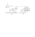
図2は、電流検出回路13,14の構成を示すものである。電流検出回路13,14は、オペアンプ60,61と抵抗及び基準電圧発生器62によって構成されている。オペアンプ60の周辺抵抗R1,R2,R3,R4は同じ抵抗値であり、入力電圧x,yの差電圧を、基準電圧Vrを基準として出力する。オペアンプ61は反転増幅器であり、オペアンプ60の出力信号を、電圧Vrを基準に増幅率Rb/Raで増幅する。
FIG. 2 shows the configuration of the
AD変換回路15は、電流検出回路13,14の出力信号をアナログ/デジタル変換すると、電流検出回路13からの出力信号の変換結果をIu、電流検出回路14からの出力信号の変換結果をIv、−Iu−IvをIwとして出力する。また、AD変換回路15は、3相ブリッジ接続された6個のFET・Fu〜Fw,Fx〜Fzよりなる通電手段(インバータ)83に供給される電源電圧をもAD変換しており、その電圧信号をVdcとして出力している。
When the
電流変換手段16は、電流Iu,Iv,Iw及び角度Θを受けて磁束軸方向成分電流Idと、磁束軸方向に直交するトルク軸方向成分電流Iqを演算する。d軸電流Idは、比較器(電圧演算手段)17によりd軸電流指令Idrと比較されてPI制御器(電圧演算手段)18に供給される。同じく、q軸電流Iqは比較器(電圧演算手段)19によりq軸電流指令Iqrと比較されてPI制御器(電圧演算手段)20に供給される。d軸電流指令Idrは、電力演算手段26により与えられる電力Wmを受けてd軸電流指令形成手段27により生成出力される。また、q軸電流指令Iqrは、q軸電流指令形成手段(振幅演算手段)25によって生成出力される。そして、PI制御器18,20は、比較器17,19より出力される信号を比例・積分処理してd軸電圧Vd及びq軸電圧Vqを形成する。
The
PWM信号形成手段21は、電圧Vd,Vqと角度Θとから所謂空間ベクトル法により3相電圧のPWM波形Vu,Vv,Vwを形成するが、信号SMにより2相変調信号パターンと3相変調信号パターンとが切り換えられるようになっている。ゲートドライブ回路80,81は、3相電圧のPWM波形Vu,Vv,Vwを増幅して、通電手段83の各ゲート端子に出力する。3相構成の通電手段83の各相出力端子は、U,V相は前記シャント抵抗11,12を介して、W相は直接モータ巻線Lu,Lv,Lwに夫々接続されている。
The PWM signal forming means 21 forms a PWM waveform Vu, Vv, Vw of a three-phase voltage from the voltages Vd, Vq and the angle Θ by a so-called space vector method, but the two-phase modulation signal pattern and the three-phase modulation signal are generated by the signal SM. The pattern can be switched. The
誘起電圧演算手段22は、電流Id,Iq及び電圧Vd,Vqが与えられて生成した信号Edを角速度演算手段23に出力する。そして、角速度演算手段23は、その信号Edより角速度ωを演算し、角度演算手段(位置推定手段)24は、角速度ωにより角度Θを生成出力する。同時に、例えば図示しない上位CPUに対し、モータ速度情報としての回転信号FGを出力している。 The induced voltage calculation means 22 outputs a signal Ed generated by being supplied with the currents Id and Iq and the voltages Vd and Vq to the angular velocity calculation means 23. Then, the angular velocity calculation means 23 calculates the angular velocity ω from the signal Ed, and the angle calculation means (position estimation means) 24 generates and outputs the angle Θ based on the angular velocity ω. At the same time, for example, a rotation signal FG as motor speed information is output to a host CPU (not shown).
スピンドルモータ制御装置1には、例えば上位CPUによってスタート/ストップ信号SOと電流指令(トルク指令)SI及び低角速度指令SFが与えられている。スタート/ストップ信号SOは、モータ始動時のシーケンス制御を行う始動制御手段(低速回転制御手段)28とモータブレーキ時のシーケンス制御を行うブレーキ制御手段29に入力され、電流指令SIはAD変換回路30を介してq軸電流指令形成手段25に、低角速度指令SFはAD変換回路31を介して始動制御手段28に入力されている。即ち、スピンドルモータ制御装置1はセンサレスベクトル制御を行うように構成されている。
The spindle
次に、本実施例の作用について図3乃至図8も参照して説明する。シャント抵抗11,12の両端電圧を受けた電流検出回路13,14により出力される信号zは(0)式のようになる。
z=(Rb/Ra)(y−x)+Vr ・・・(0)
従って、シャント抵抗11,12の夫々の両端電圧が電圧Vrを基準に増幅されて、AD変換回路15に供給される。AD変換回路15は、電流検出回路13側出力の変換結果をIu、電流検出回路14側出力の変換結果をIv、−Iu−IvをIwとして出力する。尚、AD変換回路15は、通電オフ状態(基準電圧Vr)のAD変換結果を記憶しており、これとの差としてIu,Ivを計算している。
Next, the operation of the present embodiment will be described with reference to FIGS. The signal z output from the
z = (Rb / Ra) (y−x) + Vr (0)
Accordingly, the voltages across the
電流変換手段16は、(1)式,(2)式により磁束軸方向成分電流Idと、トルク軸方向成分電流Iqを演算する。

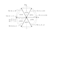
PWM信号形成手段21は、(4)式によりVαとVβを演算する。
(1)電圧ベクトルVがセクタ1に属する場合
電圧ベクトルV(Vα、Vβ)を、電圧ベクトルV1(1,0,0)の成分と電圧ベクトルV2(1,1,0)の成分とに分離して変数D1、D2を演算し、これに基づいて信号波Vu、Vvを決定する。セクタ1はW相の非スイッチング期間にあたるため、信号波Vwはゼロとなる。PWM信号形成手段21は以下の(5)式を用いて演算を行う。
(2)電圧ベクトルVがセクタ2に属する場合
電圧ベクトルVを、電圧ベクトルV2、V3の成分に分離して変数D1、D2を求め、これに基づいて信号波Vu、Vvを決定する。信号波Vwはゼロとなる。演算は、以下の(6)式により行われる。
(3)電圧ベクトルVがセクタ3に属する場合
電圧ベクトルVを、電圧ベクトルV3、V4の成分に分離して変数D1、D2を求め、これに基づいて信号波Vv、Vwを決定する。信号波Vuはゼロとなる。演算は、以下の(7)式により行われる。
(4)電圧ベクトルVがセクタ4に属する場合
電圧ベクトルVを、電圧ベクトルV4、V5の成分に分離して変数D1、D2を求め、これに基づいて信号波Vv、Vwを決定する。信号波Vuはゼロとなる。演算は、以下の(8)式により行われる。
(5)電圧ベクトルVがセクタ5に属する場合
電圧ベクトルVを、電圧ベクトルV5、V6の成分に分離して変数D1、D2を求め、これに基づいて信号波Vw、Vuを決定する。信号波Vvはゼロとなる。演算は、以下の(9)式により行われる。
(6)電圧ベクトルVがセクタ6に属する場合
電圧ベクトルVを、電圧ベクトルV6、V1の成分に分離して変数D1、D2を求め、これに基づいて信号波Vw、Vuを決定する。信号波Vvはゼロとなる。演算は、以下の(10)式により行われる。
電圧信号Vu,Vv,Vwは、PWM信号に変換されて図4に示す信号がゲートドライブ回路80,81に出力される。これらは、U相とV相及びUV間の波形を示した図4で分かるように、スイッチングしない期間が各相120度づつある信号でスイッチング損失は2ア−ム分で回路損失は比較的少ないが、スイッチング期間と非スイッチング期間が混在するために正弦波精度は比較的悪い。
The voltage signals Vu, Vv, Vw are converted into PWM signals, and the signals shown in FIG. 4 are output to the
次に、信号SMにより3相変調が選択されている場合を説明する。次の演算により信号波Vu,Vv,Vwを形成する。
(1)電圧ベクトルVがセクタ1に属する場合
電圧ベクトルVを、電圧ベクトルV1、V2の成分に分離して変数D1、D2を求め、さらに零ベクトルに対応した変数D0を求め、これらに基づいて信号波Vu、Vv、Vwを決定する。零ベクトルの発生時間に相当するD0は2分割され、PWM周期における電圧ベクトルは、例えばV0(0,0,0)、V1(1,0,0)、V2(1,1,0)、V7(1,1,1)の順に切り替えられる。演算は、以下の(11)式により行われる。
(1) When the voltage vector V belongs to the
(2)電圧ベクトルVがセクタ2に属する場合
電圧ベクトルVを、電圧ベクトルV2、V3の成分に分離して変数D1、D2、D0を求め、これらに基づいて信号波Vu、Vv、Vwを決定する。演算は、以下の(12)式により行われる。
(3)電圧ベクトルVがセクタ3に属する場合
電圧ベクトルVを、電圧ベクトルV3、V4の成分に分離して変数D1、D2、D0を求め、これらに基づいて信号波Vu、Vv、Vwを決定する。演算は、以下の(13)式により行われる。
(4)電圧ベクトルVがセクタ4に属する場合
電圧ベクトルVを、電圧ベクトルV4、V5の成分に分離して変数D1、D2、D0を求め、これらに基づいて信号波Vu、Vv、Vwを決定する。演算は、以下の(14)式により行われる。
(5)電圧ベクトルVがセクタ5に属する場合
電圧ベクトルVを、電圧ベクトルV5、V6の成分に分離して変数D1、D2、D0を求め、これらに基づいて信号波Vu、Vv、Vwを決定する。演算は、以下の(15)式により行われる。
(6)電圧ベクトルVがセクタ6に属する場合
電圧ベクトルVを、電圧ベクトルV6、V1の成分に分離して変数D1、D2、D0を求め、これらに基づいて信号波Vu、Vv、Vwを決定する。演算は、以下の(16)式により行われる。
電圧信号Vu,Vv,Vwは、PWM信号に変換されて図5に示す信号がゲートドライブ回路80,81に出力される。これらは、U相とV相及びUV間の波形を示した図5で分かるように、非スイッチング期間が無いので回路損失は比較的多いが、正弦波精度は高い。
ゲートドライブ回路80,81は、3相電圧のPWM波形Vu,Vv,Vwを増幅して、通電手段83の各ゲート端子にオンオフ信号を供給し、モータ巻線Lu,Lv,Lwに対して正弦波PWM電圧を発生させる。以って、モータ巻線Lu,Lv,Lwには正弦波電流が流れモータが回転駆動されると同時に、その電流はd軸電流指令Idr及びq軸電流指令Iqrに追従する。
The voltage signals Vu, Vv, Vw are converted into PWM signals, and the signals shown in FIG. 5 are output to the
The
次に、回転位置センサを使用することなくモータの回転角度を推定する動作について説明する。誘起電圧演算手段22は、d軸誘起電圧を(17)式で演算する。
Ed=Vd−R・Id+ωL・Iq ・・・(17)
ここでR及びLはモータの定数である。回路上のdq軸とモータのdq軸が合致している場合には、d軸誘起電圧Edはゼロになる筈であり、電圧Edがゼロで無い場合には軸が合致していないことを示している。電圧Edが正の場合はモータのdq軸に対して回路上のdq軸が進み位相、電圧Edが負の場合にはモータのdq軸に対して回路上のdq軸が遅れ位相となることから、角速度演算手段23は(18)式により角速度ωを算出する。
ω=ωo−K・Ed ・・・(18)
ここでKはゲイン定数である。角度演算手段24は角速度ωを積分することで角度Θを求めている。これらの処理が繰り返されることにより、回路上のdq軸とモータのdq軸が合致するように、角速度ω及び角度Θが演算される。
Next, an operation for estimating the rotation angle of the motor without using the rotational position sensor will be described. The induced voltage computing means 22 computes the d-axis induced voltage according to equation (17).
Ed = Vd−R · Id + ωL · Iq (17)
Here, R and L are motor constants. If the dq axis on the circuit matches the dq axis of the motor, the d axis induced voltage Ed should be zero, and if the voltage Ed is not zero, the axis does not match. ing. When the voltage Ed is positive, the dq axis on the circuit is advanced with respect to the dq axis of the motor, and when the voltage Ed is negative, the dq axis on the circuit is delayed with respect to the dq axis of the motor. The angular velocity calculation means 23 calculates the angular velocity ω by the equation (18).
ω = ωo−K · Ed (18)
Here, K is a gain constant. The angle calculation means 24 obtains the angle Θ by integrating the angular velocity ω. By repeating these processes, the angular velocity ω and the angle Θ are calculated so that the dq axis on the circuit matches the dq axis of the motor.
次にq軸の電流指令の形成動作について説明する。電流指令SIは、AD変換回路30を介してq軸電流指令形成手段25に入力されている。q軸電流指令形成手段25は、基本的に電流指令SIに応じてq軸電流指令Iqrを設定して正負の値を出力するが、出力電圧のオーバーフロー条件でq軸電流指令Iqrにリミットを掛ける。まず、(19)式により出力電圧Vout(出力線間電圧の振幅)を計算する。
Vout<0.95・Vdc Iqr=SI
0.95・Vdc≦Vout<Vdc Iqr=20・SI・(Vdc−Vout)/Vdc
Vdc≦Vout Iqr=0
・・・(20)
これにより、電源電圧Vdcと出力電圧Voutを常に監視して、オーバーフロー(Vdc≦Vout)しないようにq軸電流指令Iqrを制限するので、オーバーフローによる電圧Voutの歪を原因とする電流波形の乱れは発生しない。この動作により、通常は電流指令SIに依存してモータのq軸電流が制御される。
Next, the operation of forming a q-axis current command will be described. The current command SI is input to the q-axis current
Vout <0.95 ・ Vdc Iqr = SI
0.95 · Vdc ≦ Vout <Vdc Iqr = 20 · SI · (Vdc−Vout) / Vdc
Vdc ≦ Vout Iqr = 0
... (20)
As a result, the power supply voltage Vdc and the output voltage Vout are constantly monitored, and the q-axis current command Iqr is limited so as not to overflow (Vdc ≦ Vout). Therefore, the disturbance of the current waveform caused by the distortion of the voltage Vout due to overflow is prevented. Does not occur. By this operation, the q-axis current of the motor is normally controlled depending on the current command SI.
次に、d軸電流指令Idrの形成動作について説明する。電力演算手段26においては、(21)式により電力Wmを計算する。
Wm=3・(Vd・Id+Vq・Iq)/2 ・・・(21)
この電力Wmは通常正の値であるが、電流指令SIが負となりモータの回転にブレーキをかける時には負の値をとることがある。d軸電流指令形成手段27は、電力Wmを受けて(22)式でd軸電流指令Idrを求める。
Idr=Idr+Kw・Wm ・・・(22)
但し、Idr≦0
よって、電力Wmが正の場合、d軸電流指令Idrはゼロを維持し、電力Wmが負になったときにd軸電流指令Idrは負方向に変化する。その後に電力Wmが正に戻ったときにはd軸電流指令Idrもゼロ方向に変化する。この動作によりd軸電流が制御されるが、d軸電流はトルクに寄与しない電流であり、巻線抵抗での熱を発生させる効果がある。電力が負となったとき、即ち、モータの回転にブレーキをかけた場合に発生した電圧が、通電手段83を介して電源側に回生する状態となったときにd軸電流を増加させれば、巻線での発熱により電力を消費して、回生状態を回避することが出来る。
Next, the operation for forming the d-axis current command Idr will be described. In the power calculation means 26, the power Wm is calculated by the equation (21).
Wm = 3 · (Vd · Id + Vq · Iq) / 2 (21)
This electric power Wm is usually a positive value, but may take a negative value when the current command SI is negative and the motor is braked. The d-axis current
Idr = Idr + Kw · Wm (22)
However, Idr ≦ 0
Therefore, when the power Wm is positive, the d-axis current command Idr maintains zero, and when the power Wm becomes negative, the d-axis current command Idr changes in the negative direction. Thereafter, when the power Wm returns to positive, the d-axis current command Idr also changes in the zero direction. Although the d-axis current is controlled by this operation, the d-axis current is a current that does not contribute to torque, and has an effect of generating heat at the winding resistance. If the d-axis current is increased when the electric power becomes negative, that is, when the voltage generated when the motor is braked is regenerated to the power supply side via the energizing means 83, The electric power is consumed by the heat generated in the winding, and the regenerative state can be avoided.
次に、始動制御手段28の作用について図7のフローチャートを参照して説明する。始動制御手段28は、スタート/ストップ信号SOがストップからスタートに変化したときに処理を開始し、これまでに説明した各手段に働きかけて各変数を制御する。
(1)位置決め段階
最初はロータの位置決めを行う。この位置決め段階では、d軸電流指令形成手段27に働きかけて電流指令Idrをゼロから電流指令SIに増加させると共に、角速度演算手段23の出力ωをゼロ、角度演算手段24の出力Θをゼロに初期化する。q軸電流指令形成手段25によるIqrはゼロに初期化されている。これによりモータに所定の通電が成されてロータは所定の位置に停止する。この際の通電は信号SMにより3相変調に設定する。この位置決め段階は所定時間で終了して次の強制回転段階に移行する。
Next, the operation of the start control means 28 will be described with reference to the flowchart of FIG. The start control means 28 starts processing when the start / stop signal SO changes from stop to start, and works on each means described so far to control each variable.
(1) Positioning stage Initially, the rotor is positioned. In this positioning stage, the d-axis current
(2)強制回転段階
次の強制回転段階では、角速度演算手段23の出力ωを増加させることで、角度演算手段24の出力Θも変化してモータは回転を始める。この際、角速度ωの増加は例えば(23)式により行われる。尚、Kyは定数である。
ω=ω+Ky・SI ・・・(23)
つまり、電流指令SIが小さいときには加速が遅く、大きいときには急加速となるように制御している。角速度ωは低角速度指令SFにより制限されており、SFより大きくはならない。従って、低角速度指令SFが所定値ωs未満の場合は、SFの角速度で強制回転を継続する。モータにおいて発生する誘起電圧が小さい低角速度の範囲では、低角速度指令SFに応じて回転する。
(2) Forced rotation stage In the next forced rotation stage, by increasing the output ω of the angular
ω = ω + Ky · SI (23)
That is, the control is performed so that the acceleration is slow when the current command SI is small and the acceleration is rapid when the current command SI is large. The angular velocity ω is limited by the low angular velocity command SF and cannot be larger than SF. Therefore, when the low angular velocity command SF is less than the predetermined value ωs, the forced rotation is continued at the angular velocity of SF. In the range of low angular velocity where the induced voltage generated in the motor is small, the motor rotates in accordance with the low angular velocity command SF.
低角速度指令SFの値が所定値ωs以上の場合について引き続き説明する。角速度ωsはモータにおいて誘起電圧が十分に発生する角速度であり、誘起電圧演算手段22においてd軸誘起電圧Edの演算が可能となる。角速度ωが所定値ωsに達したときに次の切換段階に移行する。
(3)切換段階
切換段階では、d軸電流指令Idrを電流指令SIからゼロに、q軸電流指令Iqrをゼロから電流指令SIに角速度ωsで変化させる((24)式)。同時に、角速度演算手段23の出力ωをゼロとして、角度演算手段24の出力Θの変化を停止させる。
Idr=SI・cos(ωs・t)
Iqr=SI・sin(ωs・t) ・・・(24)
この切換段階では、更に、誘起電圧演算手段22のd軸誘起電圧Edを監視している。上記の電流の変化によってd軸誘起電圧Edはプラスからマイナス方向に変化する。d軸誘起電圧Edがゼロになった時点で、角速度演算手段23の前記した演算結果を採用して角速度ωとする。以降、角速度ωはd軸誘起電圧Edに応じて増加するクローズループ状態となり、次の定常段階に移行する。
The case where the value of the low angular velocity command SF is equal to or greater than the predetermined value ωs will be described continuously. The angular velocity ωs is an angular velocity at which an induced voltage is sufficiently generated in the motor, and the induced voltage calculation means 22 can calculate the d-axis induced voltage Ed. When the angular velocity ω reaches the predetermined value ωs, the operation proceeds to the next switching stage.
(3) Switching stage In the switching stage, the d-axis current command Idr is changed from the current command SI to zero, and the q-axis current command Iqr is changed from zero to the current command SI at the angular velocity ωs (Equation (24)). At the same time, the output ω of the angular velocity calculation means 23 is set to zero, and the change in the output Θ of the angle calculation means 24 is stopped.
Idr = SI · cos (ωs · t)
Iqr = SI · sin (ωs · t) (24)
In this switching stage, the d-axis induced voltage Ed of the induced voltage calculation means 22 is further monitored. The d-axis induced voltage Ed changes from plus to minus due to the change in current. When the d-axis induced voltage Ed becomes zero, the calculation result of the angular velocity calculation means 23 is adopted to obtain the angular velocity ω. Thereafter, the angular velocity ω enters a closed loop state that increases in accordance with the d-axis induced voltage Ed, and shifts to the next steady stage.
(4)定常段階
定常段階では、d軸電流指令Idrはゼロ、q軸電流指令Iqrは電流指令SIに応じる。この際、モータの回転数が所定回転数を越えたときには、信号SMを2相変調側に設定する。以上により、センサレス方式でありながら、電流指令に追従した正弦波電流の始動が可能である。この状態は、スタート/ストップ信号SOがストップに変化するまで継続される。
(4) Steady stage In the steady stage, the d-axis current command Idr is zero, and the q-axis current command Iqr is in accordance with the current command SI. At this time, when the rotational speed of the motor exceeds a predetermined rotational speed, the signal SM is set to the two-phase modulation side. As described above, it is possible to start a sine wave current following the current command while using the sensorless method. This state continues until the start / stop signal SO changes to stop.
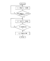
次に、ブレーキ制御手段29について図8のフローチャ−トを参照して説明する。ブレーキ制御手段29は、スタート/ストップ信号SOがスタートからストップに変化したときに処理を開始し、各手段に働きかけて各変数を制御する。ブレーキが必要とされるときには、上位CPUからスピンドルモータ制御装置1に対して、例えばスタート/ストップ信号SOをストップとすると同時に、負の電流指令SIが入力される。
Next, the brake control means 29 will be described with reference to the flowchart of FIG. The brake control means 29 starts processing when the start / stop signal SO changes from start to stop, and works on each means to control each variable. When braking is required, for example, the start / stop signal SO is stopped and the negative current command SI is input to the spindle
(1)短絡ブレーキ段階
短絡ブレーキ段階では、信号SMを2相変調側に設定すると同時に、PI制御器18,20に働きかけて電圧Vd,Vqをゼロにする。これにより、PWM信号形成手段21の出力は3相共「ロー」となって、通電手段83の下側FET・Fx,Fy,Fzがオンする。以って巻線Lu,Lv,Lwは下側FET・Fx,Fy,Fzを介して短絡状態となり、ブレーキ力が発生する。この短絡ブレーキ段階は、所定回転数以上の場合または所定時間以内で継続され、この条件から外れたときに次の回生ブレーキ段階に移行する。
(1) Short-circuit brake stage In the short-circuit brake stage, the signal SM is set to the two-phase modulation side, and at the same time, the
(2)回生ブレーキ段階
回生ブレーキ段階では、負の電流指令SIからq軸電流指令形成手段25を介して負のq軸電流指令Iqrが形成され、電流制御ループによりモータのq軸電流が制御される。これと同時に、電力演算手段26により電力が演算されて、負の場合にはd軸電流指令形成手段27により負のd軸電流指令Idrが形成される。以上により、電力が負にならないように制御されたブレーキ動作が行われる。また、ブレーキ力は電流指令SIに依存する。信号SMは、回転数に応じて2相変調/3相変調が切替え設定される。回生ブレーキ段階によりモータは減速されるが、低速回転では誘起電圧の検出によるモータ回転角の推定に限界が生じる。即ち、所定回転数ωs以下になった場合は回生ブレーキ段階が継続できなくなるために、次の位置決め段階に移行する。
(2) Regenerative braking stage In the regenerative braking stage, the negative q-axis current command Iqr is formed from the negative current command SI via the q-axis current
(3)位置決め段階
位置決め段階では、角速度演算手段23の出力ωをゼロとすることで角度演算手段24の出力Θを固定する。これと同時に、d軸電流指令形成手段27に働きかけて電流指令Idrをゼロから電流指令SIの絶対値に増加させると共に、q軸電流指令形成手段25によるIqrはゼロにする。すると位置決めのトルクが発生してモータは停止する。この位置決め段階は所定時間継続後に終了する。
(3) Positioning Stage In the positioning stage, the output ω of the angular computing means 24 is fixed by setting the output ω of the angular velocity computing means 23 to zero. At the same time, the d-axis current
以上のように本実施例によれば、電流変換手段16は、永久磁石モータの3相巻線Lu,Lv,Lwに流れる電流から磁束軸方向成分であるd軸電流とトルク軸方向成分であるq軸電流とを演算し、d軸電流指令形成手段27は、永久磁石モータの電力Wmに基づいてd軸電流指令Idrを演算し、q軸電流指令形成手段25は、外部より与えられる電流指令SIに基づいてq軸電流指令Iqrを演算する。また、PI制御器18及び20は、d軸及びq軸電流指令Idr及びIqrとd軸及びq軸電流Id及びIqとに基づいてd軸及びq軸電圧Vd及びVqを演算する。
As described above, according to the present embodiment, the current conversion means 16 is the d-axis current and the torque axis direction component that are the magnetic flux axis direction components from the current flowing through the three-phase windings Lu, Lv, and Lw of the permanent magnet motor. calculates a q-axis current, d-axis current
そして、誘起電圧演算手段22がd軸及びq軸電流Id及びIqとd軸電圧Vdとに基づいてd軸誘起電圧Edを演算すると、角速度演算手段23は、そのd軸誘起電圧Edに基づいてロータの角速度ωを決定し、角度演算手段24は、その角速度からロータの回転位置Θを推定する。更に、PWM信号形成手段21は、d軸及びq軸電圧Vd及びVq並びに前記回転位置Θから3相のPWM信号Vu,Vv,Vwを形成し、通電手段83は、3相PWM信号Vu,Vv,Vwに基づいて永久磁石モータの巻線Lu,Lv,Lwに通電を行なうようにした。
従って、センサレス方式により永久磁石モータに正弦波通電を実行できるので、低コストで高効率のスピンドルモータ駆動を行うことができる。また、ベクトル制御によりモータ電流をd/q軸に分離し、加速中にはトルクの発生に寄与しないd軸電流Idをゼロに制御するので、電圧制御の場合と比較して加速能力を最大化できる。
Then, when the induced voltage calculating means 22 calculates the d-axis induced voltage Ed based on the d-axis and q-axis currents Id and Iq and the d-axis voltage Vd, the angular
Accordingly, since the sine wave energization can be executed on the permanent magnet motor by the sensorless method, the spindle motor can be driven at a low cost and with high efficiency. In addition, the motor current is separated into the d / q axes by vector control, and the d-axis current Id that does not contribute to torque generation is controlled to zero during acceleration, maximizing acceleration capacity compared to voltage control. it can.
また、始動制御手段28は、通電手段83を制御することでモータの位置決めを行うと、強制転流によりモータの始動を開始させ、強制転流から3相PWM信号Vu,Vv,Vwに基づく通電に切り換えることで始動制御を行うので、センサレス方式でも安定して始動を行うことができる。そして、強制回転中の加速度を電流指令SIの関数として制御するので、幅広い電流指令に対応した始動が可能である。更に、始動制御手段28は、外部からの低速指令SFを受けた場合に、強制転流で角速度ωを制御して低速回転を行うので、センサレスベクトル制御方式であっても低角速度領域での回転が可能となり、DVD、CD、HDDなどの複数のディスク記録媒体を回転駆動できる。 Further, when the start control means 28 controls the energization means 83 to position the motor, the start control means 28 starts the motor start by forced commutation, and the energization based on the three-phase PWM signals Vu, Vv, Vw from the forced commutation. Since the start control is performed by switching to, the sensor can be stably started even in the sensorless system. Since the acceleration during forced rotation is controlled as a function of the current command SI, starting corresponding to a wide range of current commands is possible. Further, when the start control means 28 receives a low speed command SF from the outside, the start control means 28 performs the low speed rotation by controlling the angular speed ω by forced commutation. Therefore, even in the sensorless vector control system, the rotation in the low angular speed region is performed. Thus, a plurality of disc recording media such as DVD, CD, and HDD can be rotationally driven.
また、ブレーキ制御手段29は、永久磁石モータの回転にブレーキをかける場合に、所定時間若しくは所定回転数以上で短絡ブレーキを行った後、外部より与えられる負の電流指令SIに対応して巻線に通電を行い位置決めを行うように制御するので、センサレス方式でも安定した停止動作が実現できる。そして、d軸電流指令形成手段27は、モータにブレーキを作用させる場合にd軸電流指令Idrを出力してモータ電力を制御するようにした。即ち、従来構成では、ブレーキ時に発生する回生電力によって電源電圧が上昇し、制御ICが破壊されてしまうおそれがあったが、本発明によれば回生電力による電源電圧の上昇を抑制することができる。
Further, the brake control means 29 performs a short-circuit brake for a predetermined time or at a predetermined rotation speed or higher when braking the rotation of the permanent magnet motor, and then performs winding corresponding to the negative current command SI given from the outside. Therefore, stable stop operation can be realized even with a sensorless system. The d-axis current
また、PWM信号形成手段21は、2相変調及び3相変調に応じた出力波形を選択可能であり、永久磁石モータの低速回転領域で3相変調を選択し、高速回転領域で2相変調を選択するので、低角速度領域では波形精度を重視して3相変調を行い、高角速度領域では2相変調を行うことでスイッチング損失を低減して発熱を抑制できる。加えて、q軸電流指令形成手段25は、出力電圧振幅Voutを演算し、電源電圧Vdcとの比較結果に応じてq軸電流指令Iqrを制限するので、出力電圧のオーバーフローを防止して正弦波電流の歪による振動を抑制することができる。
Further, the PWM signal forming means 21 can select an output waveform corresponding to two-phase modulation and three-phase modulation, selects three-phase modulation in the low-speed rotation region of the permanent magnet motor, and performs two-phase modulation in the high-speed rotation region. Therefore, three-phase modulation is performed with emphasis on waveform accuracy in the low angular velocity region, and two-phase modulation is performed in the high angular velocity region, thereby reducing switching loss and suppressing heat generation. In addition, the q-axis current
(第2実施例)
図9は本発明の第2実施例を示すものであり、第1実施例と同一部分には同一符号を付して説明を省略し、以下異なる部分についてのみ説明する。第2実施例のスピンドルモータ制御装置40は、スピンドルモータ制御装置1の内、図9の破線で囲んだ部分を例えばマイクロコンピュ−タ41などの演算器を用いて構成し、ベクトル制御演算を、PWM周期またはその整数倍の周期で実行するように構成したものである。
(Second embodiment)
FIG. 9 shows a second embodiment of the present invention. The same parts as those of the first embodiment are denoted by the same reference numerals and the description thereof is omitted. Only different parts will be described below. In the spindle
(第3実施例)
図10は本発明の第3実施例を示すものである。第3実施例のスピンドルモータ制御装置42は、図10の破線で囲んだ部分をマイクロコンピュータ43などにより構成してソフトウエアで演算処理を行なう。そして、第1実施例におけるPWM信号形成手段21に相当する部分は、PWM信号形成手段51と電圧変換手段52とに置き換えられている。
マイクロコンピュータ43の電圧演算手段52は、電圧Vd,Vqを受けて(25)式により、電圧の振幅Vampと位相Vphsとを出力する。
FIG. 10 shows a third embodiment of the present invention. The spindle
The voltage calculation means 52 of the
角度演算手段24及びPWM信号形成手段51は、演算処理をPWM周期またはその整数倍の周期で実行し、マイクロコンピュータ43におけるソフトウエア処理は、それよりも長い周期で実行される。以上のように構成された第3実施例によれば、能力の低いマイクロコンピュータを使用することができ、低コストのスピンドルモータ制御装置42を実現できる。
The angle calculation means 24 and the PWM signal forming means 51 execute calculation processing at a PWM cycle or a cycle that is an integer multiple thereof, and the software processing in the
本発明は上記し又は図面に記載した実施例にのみ限定されるものではなく、以下のような変形が可能である。
3相巻線のうち2相のみにシャント抵抗を配置したが、3相バランスを取るために3相全ての巻線にシャント抵抗を配置することが望ましい。
必ずしも回転速度に応じて2相変調と3相変調とを切替える必要はなく、全ての回転速度に亘って3相変調のみを行っても良い。
モータを始動させる場合のシーケンスは図7に示すものに限らない。例えば、(3)の切換段階を省略しても良い。
The present invention is not limited to the embodiments described above or shown in the drawings, and the following modifications are possible.
Although shunt resistors are arranged only in two phases of the three-phase windings, it is desirable to arrange shunt resistors in all three-phase windings in order to achieve a three-phase balance.
It is not always necessary to switch between two-phase modulation and three-phase modulation according to the rotation speed, and only three-phase modulation may be performed over all rotation speeds.
The sequence for starting the motor is not limited to that shown in FIG. For example, the switching step (3) may be omitted.
また、始動シーケンスの(2)強制回転段階においては、必ずしも加速率をq軸電流指令Iqrに応じて変化させる必要はなく、加速率を一定に設定しても良い。
低速回転制御手段は、個別の設計に応じて低速回転を行う必要がある場合に設ければ良い。
q軸電流指令Iqrを、出力電圧振幅Voutと電源電圧Vdcとの比較結果に応じて制限する処理も、必要に応じて行えば良い。
また、回転中のモータにブレーキをかけて停止させる場合のシーケンスは図8に示すものに限らない。例えば、(1)の短絡ブレーキ段階、または(2)の回生ブレーキ段階を省略しても良い。
Further, in the (2) forced rotation stage of the start sequence, the acceleration rate does not necessarily have to be changed according to the q-axis current command Iqr, and the acceleration rate may be set constant.
The low speed rotation control means may be provided when it is necessary to perform low speed rotation according to individual design.
The process of limiting the q-axis current command Iqr according to the comparison result between the output voltage amplitude Vout and the power supply voltage Vdc may be performed as necessary.
Moreover, the sequence in the case of stopping by applying a brake to the rotating motor is not limited to that shown in FIG. For example, the short-circuit brake stage (1) or the regenerative brake stage (2) may be omitted.
図面中、1はスピンドルモータ制御装置、Lu,Lv,Lwは巻線、11,12はシャント抵抗(電流検出手段)、13,14は電流検出回路(電流検出手段)、16は電流変換手段、17は比較器(電圧演算手段)、18はPI制御器(電圧演算手段)、19は比較器(電圧演算手段)、20はPI制御器(電圧演算手段)、21はPWM信号形成手段、22は誘起電圧演算手段、23は角速度演算手段、24は角度演算手段(位置推定手段)、25はq軸電流指令形成手段(振幅演算手段)、26は電力演算手段、27はd軸電流指令形成手段、40スピンドルモータ制御装置、41はマイクロコンピュータ、42スピンドルモータ制御装置、43はマイクロコンピュータ、51はPWM信号形成手段、52は電圧変換手段、83は通電手段である。
In the drawing, 1 is a spindle motor control device, Lu, Lv and Lw are windings, 11 and 12 are shunt resistors (current detection means), 13 and 14 are current detection circuits (current detection means), 16 is current conversion means,
Claims (4)
前記3相巻線の電流を検出する電流検出手段と、
前記3相巻線の電流から、前記永久磁石モータの磁束軸方向成分電流(d軸電流)と、これに直交するトルク軸方向成分電流(q軸電流)とを演算する電流変換手段と、
前記永久磁石モータの電力を演算する電力演算手段と、
前記電力に基づいてd軸電流指令を演算するd軸電流指令形成手段と、
外部より与えられる電流指令に基づいてq軸電流指令を演算するq軸電流指令形成手段と、
前記d軸電流指令、前記q軸電流指令、前記d軸電流、前記q軸電流に基づいて、d軸電圧及びq軸電圧を演算する電圧演算手段と、
前記d軸電流、前記q軸電流、前記d軸電圧に基づいてd軸誘起電圧を演算する誘起電圧演算手段と、
前記d軸誘起電圧に基づいて前記ロータの角速度を決定する角速度演算手段と、
前記角速度に基づいて前記ロータの回転位置を推定する位置推定手段と、
前記d軸電圧及び前記q軸電圧並びに前記回転位置から3相のPWM信号を形成するPWM信号形成手段と、
前記3相のPWM信号に基づいて、前記永久磁石モータの巻線に通電を行なう通電手段と、
前記永久磁石モータの回転にブレーキをかける場合に、所定時間若しくは所定回転数以上で短絡ブレーキを行った後に回生ブレーキを行い、その後、所定回転数以下で外部より与えられる負の電流指令SIに対応して前記3相巻線に通電することで位置決めを行うように制御するブレーキ制御手段とを備えたことを特徴とするモータ制御装置。 A permanent magnet motor comprising a rotor having a permanent magnet and a stator provided with a three-phase winding;
Current detecting means for detecting a current of the three-phase winding;
Current conversion means for calculating a magnetic flux axial direction component current (d-axis current) of the permanent magnet motor and a torque axial direction component current (q-axis current) orthogonal thereto from the current of the three-phase winding;
Power calculating means for calculating the power of the permanent magnet motor;
D-axis current command forming means for calculating a d-axis current command based on the power;
Q-axis current command forming means for calculating a q-axis current command based on a current command given from outside;
Voltage calculating means for calculating a d-axis voltage and a q-axis voltage based on the d-axis current command, the q-axis current command, the d-axis current, and the q-axis current;
Induced voltage calculation means for calculating a d-axis induced voltage based on the d-axis current, the q-axis current, and the d-axis voltage;
Angular velocity calculation means for determining the angular velocity of the rotor based on the d-axis induced voltage;
Position estimating means for estimating the rotational position of the rotor based on the angular velocity;
PWM signal forming means for forming a three-phase PWM signal from the d-axis voltage, the q-axis voltage, and the rotational position;
Energization means for energizing the windings of the permanent magnet motor based on the three-phase PWM signal ;
When braking the rotation of the permanent magnet motor, regenerative braking is performed after short-circuit braking is performed for a predetermined time or a predetermined number of revolutions or more, and then a negative current command SI given from the outside at a predetermined number of revolutions or less is supported. And a brake control means for controlling to perform positioning by energizing the three-phase winding .
Priority Applications (1)
| Application Number | Priority Date | Filing Date | Title |
|---|---|---|---|
| JP2004317948A JP4723846B2 (en) | 2004-11-01 | 2004-11-01 | Motor control device |
Applications Claiming Priority (1)
| Application Number | Priority Date | Filing Date | Title |
|---|---|---|---|
| JP2004317948A JP4723846B2 (en) | 2004-11-01 | 2004-11-01 | Motor control device |
Publications (3)
| Publication Number | Publication Date |
|---|---|
| JP2006129663A JP2006129663A (en) | 2006-05-18 |
| JP2006129663A5 JP2006129663A5 (en) | 2007-12-13 |
| JP4723846B2 true JP4723846B2 (en) | 2011-07-13 |
Family
ID=36723738
Family Applications (1)
| Application Number | Title | Priority Date | Filing Date |
|---|---|---|---|
| JP2004317948A Expired - Fee Related JP4723846B2 (en) | 2004-11-01 | 2004-11-01 | Motor control device |
Country Status (1)
| Country | Link |
|---|---|
| JP (1) | JP4723846B2 (en) |
Families Citing this family (7)
| Publication number | Priority date | Publication date | Assignee | Title |
|---|---|---|---|---|
| JP5159465B2 (en) | 2008-06-24 | 2013-03-06 | 株式会社東芝 | Motor control device and semiconductor integrated circuit device |
| JP2010115090A (en) | 2008-11-10 | 2010-05-20 | Ricoh Co Ltd | Motor drive |
| JP5530905B2 (en) * | 2010-11-19 | 2014-06-25 | 日立アプライアンス株式会社 | Motor controller, air conditioner |
| JP2013046514A (en) * | 2011-08-25 | 2013-03-04 | Semiconductor Components Industries Llc | Drive signal generation circuit |
| JP6124808B2 (en) * | 2014-01-10 | 2017-05-10 | 三菱電機株式会社 | Control device and control method for synchronous motor |
| JP2017112750A (en) * | 2015-12-17 | 2017-06-22 | パナソニックIpマネジメント株式会社 | Motor control device and washing machine or washing and drying machine in which the same is incorporated |
| JP6833638B2 (en) * | 2017-07-21 | 2021-02-24 | 株式会社東芝 | Evaluation device and evaluation method for inverter circuits for electric motors |
Citations (6)
| Publication number | Priority date | Publication date | Assignee | Title |
|---|---|---|---|---|
| JPS6264290A (en) * | 1985-09-13 | 1987-03-23 | Matsushita Refrig Co | Brushless dc motor |
| JPH0622588A (en) * | 1992-07-07 | 1994-01-28 | Nippondenso Co Ltd | Controller for brushless motor |
| JPH07236295A (en) * | 1994-02-23 | 1995-09-05 | Yaskawa Electric Corp | Method for driving and controlling internal-magnet type brushless dc motor |
| JP2001095300A (en) * | 1999-09-20 | 2001-04-06 | Hitachi Ltd | Device for controlling permanent magnet synchronous motor |
| JP2003199381A (en) * | 2001-12-27 | 2003-07-11 | Aisin Aw Co Ltd | Motor controller |
| JP2004072906A (en) * | 2002-08-06 | 2004-03-04 | Toshiba Corp | Vector control inverter arrangement |
-
2004
- 2004-11-01 JP JP2004317948A patent/JP4723846B2/en not_active Expired - Fee Related
Patent Citations (6)
| Publication number | Priority date | Publication date | Assignee | Title |
|---|---|---|---|---|
| JPS6264290A (en) * | 1985-09-13 | 1987-03-23 | Matsushita Refrig Co | Brushless dc motor |
| JPH0622588A (en) * | 1992-07-07 | 1994-01-28 | Nippondenso Co Ltd | Controller for brushless motor |
| JPH07236295A (en) * | 1994-02-23 | 1995-09-05 | Yaskawa Electric Corp | Method for driving and controlling internal-magnet type brushless dc motor |
| JP2001095300A (en) * | 1999-09-20 | 2001-04-06 | Hitachi Ltd | Device for controlling permanent magnet synchronous motor |
| JP2003199381A (en) * | 2001-12-27 | 2003-07-11 | Aisin Aw Co Ltd | Motor controller |
| JP2004072906A (en) * | 2002-08-06 | 2004-03-04 | Toshiba Corp | Vector control inverter arrangement |
Also Published As
| Publication number | Publication date |
|---|---|
| JP2006129663A (en) | 2006-05-18 |
Similar Documents
| Publication | Publication Date | Title |
|---|---|---|
| US7750586B2 (en) | Drive control device of motor and a method of start-up | |
| US7071640B2 (en) | Rotation drive control circuit of multiphases direct current motor and the start-up method thereof | |
| JP5853097B2 (en) | Three-phase synchronous motor drive device, integrated three-phase synchronous motor, positioning device and pump device | |
| US7723937B2 (en) | Drive control device of motor and a method of start-up | |
| JP4294602B2 (en) | Rotor magnetic pole position detecting device for multiphase motor, motor driving device including the same, and motor driving method | |
| JP3755424B2 (en) | AC motor drive control device | |
| JP4261523B2 (en) | Motor driving apparatus and driving method | |
| JP4723883B2 (en) | Motor control device | |
| JP4805329B2 (en) | Control device for calculating power consumption of industrial machinery | |
| JP4067949B2 (en) | Motor control device | |
| JP3236983B2 (en) | Power converter | |
| JP2009077503A (en) | Motor controller and controller for air conditioner | |
| JP4723846B2 (en) | Motor control device | |
| JP2004242417A (en) | Motor driver | |
| JP2011200068A (en) | Motor control apparatus and fan device | |
| JP3279457B2 (en) | Control device for permanent magnet synchronous motor | |
| JP4799035B2 (en) | Motor control device and motor control method | |
| JP2009136034A (en) | Motor control device | |
| CN111049433A (en) | Magnetic pole initial position detection device and magnetic pole position detection device | |
| JP2006081396A (en) | Rotary drive controller for three-phase motor | |
| CN112335170A (en) | Motor control device, motor control method, and motor system | |
| JP4154687B2 (en) | Motor control device | |
| JP5262521B2 (en) | Inverter control device | |
| JP3475367B2 (en) | DC brushless motor drive | |
| JP2023106960A (en) | Semiconductor device, motor drive system, and control method |
Legal Events
| Date | Code | Title | Description |
|---|---|---|---|
| A521 | Written amendment |
Free format text: JAPANESE INTERMEDIATE CODE: A523 Effective date: 20071025 |
|
| A621 | Written request for application examination |
Free format text: JAPANESE INTERMEDIATE CODE: A621 Effective date: 20071025 |
|
| A977 | Report on retrieval |
Free format text: JAPANESE INTERMEDIATE CODE: A971007 Effective date: 20101001 |
|
| A131 | Notification of reasons for refusal |
Free format text: JAPANESE INTERMEDIATE CODE: A131 Effective date: 20101005 |
|
| A521 | Written amendment |
Free format text: JAPANESE INTERMEDIATE CODE: A523 Effective date: 20101206 |
|
| TRDD | Decision of grant or rejection written | ||
| A01 | Written decision to grant a patent or to grant a registration (utility model) |
Free format text: JAPANESE INTERMEDIATE CODE: A01 Effective date: 20110315 |
|
| A01 | Written decision to grant a patent or to grant a registration (utility model) |
Free format text: JAPANESE INTERMEDIATE CODE: A01 |
|
| A61 | First payment of annual fees (during grant procedure) |
Free format text: JAPANESE INTERMEDIATE CODE: A61 Effective date: 20110408 |
|
| FPAY | Renewal fee payment (event date is renewal date of database) |
Free format text: PAYMENT UNTIL: 20140415 Year of fee payment: 3 |
|
| R151 | Written notification of patent or utility model registration |
Ref document number: 4723846 Country of ref document: JP Free format text: JAPANESE INTERMEDIATE CODE: R151 |
|
| FPAY | Renewal fee payment (event date is renewal date of database) |
Free format text: PAYMENT UNTIL: 20140415 Year of fee payment: 3 |
|
| LAPS | Cancellation because of no payment of annual fees |