JP4722569B2 - Fuel cell vehicle - Google Patents
Fuel cell vehicle Download PDFInfo
- Publication number
- JP4722569B2 JP4722569B2 JP2005162396A JP2005162396A JP4722569B2 JP 4722569 B2 JP4722569 B2 JP 4722569B2 JP 2005162396 A JP2005162396 A JP 2005162396A JP 2005162396 A JP2005162396 A JP 2005162396A JP 4722569 B2 JP4722569 B2 JP 4722569B2
- Authority
- JP
- Japan
- Prior art keywords
- fuel cell
- side frame
- cross member
- frame
- vehicle
- Prior art date
- Legal status (The legal status is an assumption and is not a legal conclusion. Google has not performed a legal analysis and makes no representation as to the accuracy of the status listed.)
- Expired - Fee Related
Links
Images


Classifications
-
- Y—GENERAL TAGGING OF NEW TECHNOLOGICAL DEVELOPMENTS; GENERAL TAGGING OF CROSS-SECTIONAL TECHNOLOGIES SPANNING OVER SEVERAL SECTIONS OF THE IPC; TECHNICAL SUBJECTS COVERED BY FORMER USPC CROSS-REFERENCE ART COLLECTIONS [XRACs] AND DIGESTS
- Y02—TECHNOLOGIES OR APPLICATIONS FOR MITIGATION OR ADAPTATION AGAINST CLIMATE CHANGE
- Y02E—REDUCTION OF GREENHOUSE GAS [GHG] EMISSIONS, RELATED TO ENERGY GENERATION, TRANSMISSION OR DISTRIBUTION
- Y02E60/00—Enabling technologies; Technologies with a potential or indirect contribution to GHG emissions mitigation
- Y02E60/30—Hydrogen technology
- Y02E60/50—Fuel cells
Landscapes
- Electric Propulsion And Braking For Vehicles (AREA)
- Fuel Cell (AREA)
- Body Structure For Vehicles (AREA)
- Arrangement Or Mounting Of Propulsion Units For Vehicles (AREA)
Description
この発明は、燃料電池によって走行用モータを駆動し走行する燃料電池自動車に関するものである。 The present invention relates to a fuel cell vehicle that travels by driving a driving motor with a fuel cell.
この種の燃料電池自動車においては、燃料電池やその補機類が搭載されたサブフレームを車体骨格メンバにその下方から締結し、車体フロア下に配置したものが知られている(例えば、特許文献1参照)。
ところで、このように車体フロア下に燃料電池等を配置する場合には、車体フロアの低床化に課題があった。というのは、従来はサブフレームの上に燃料電池を設置しているため、サブフレームの下端から車体フロアまでの寸法として、少なくともサブフレームの高さ方向の部材寸法と燃料電池の高さ寸法とを加算した寸法が必要で、これが低床化の障害になっていた。
そこで、この発明は、車両を低床化することができる燃料電池自動車を提供するものである。
By the way, when a fuel cell or the like is disposed under the vehicle body floor as described above, there has been a problem in lowering the vehicle body floor. This is because, since the fuel cell is conventionally installed on the subframe, the dimension from the lower end of the subframe to the vehicle body floor is at least the member dimension in the height direction of the subframe and the height dimension of the fuel cell. The dimension which added was necessary, and this became the obstacle of the low floor.
Accordingly, the present invention provides a fuel cell vehicle capable of lowering the floor of the vehicle.
上記課題を解決するために、請求項1に係る発明は、水素と酸素の電気化学反応によって発電を行う燃料電池(例えば、後述する実施例における燃料電池2)を搭載した燃料電池用サブフレーム(例えば、後述する実施例における燃料電池用サブフレーム30)を備えた燃料電池自動車(例えば、後述する実施例における燃料電池自動車1)であって、前記燃料電池用サブフレームは、車体の前後方向に延びる左右のサイドフレーム(例えば、後述する実施例におけるサイドフレーム31)と、車幅方向に延び前記左右のサイドフレームを連結する複数のクロスメンバ(例えば、後述する実施例におけるクロスメンバ40A〜40E)によって構成され、前記サイドフレームはアッパーサイドフレーム(例えば、後述する実施例におけるアッパサイドフレーム32)とロアサイドフレーム(例えば、後述する実施例におけるロアサイドフレーム33)とを結合して閉断面形状に構成されており、前記アッパーサイドフレームの車幅方向内側に形成された開口(例えば、後述する実施例における開口35a)から前記クロスメンバの端部が挿入され、前記アッパーサイドフレームと前記ロアサイドフレームはカラー(例えば、後述する実施例におけるカラー50)を介在させて前記クロスメンバの端部を挟持し、前記アッパーサイドフレームと前記ロアサイドフレームと前記クロスメンバの端部が、前記カラーを挿通する共通のボルト(例えば、後述する実施例におけるボルト55)によって車体のフロアフレーム(例えば、後述する実施例におけるフロアフレーム19)にその下方から一体的に締結されており、前記燃料電池は、互いに隣り合う一対の前記クロスメンバ(例えば、後述する実施例におけるクロスメンバ40B,40C)間に配置され、該燃料電池の下端(例えば、後述する実施例における下端2a)を該クロスメンバの上端と下端の間に位置させて、該燃料電池の前端部と後端部が該クロスメンバに締結されていることを特徴とする燃料電池自動車である。
このように構成することにより、サブフレームと燃料電池とを高さ方向に一部重複させて配置することができるので、サブフレームに燃料電池を搭載してなるユニットとしての全高を低くすることができるとともに、サイドフレームとクロスメンバの連結部の機械的強度を高めることができ、且つ、サイドフレームとクロスメンバとを一体的にフロアフレームに連結することができ、この連結部の機械的強度を高めることができる。
In order to solve the above-mentioned problems, the invention according to
By configuring in this way, the subframe and the fuel cell can be partially overlapped in the height direction, so that the overall height as a unit in which the fuel cell is mounted on the subframe can be reduced. In addition, the mechanical strength of the connecting portion between the side frame and the cross member can be increased, and the side frame and the cross member can be integrally connected to the floor frame. Can be increased.
請求項2に係る発明は、請求項1に記載の発明において、前記サイドフレームの下端は前後輪タイヤ(例えば、後述する実施例における前輪タイヤ15A,後輪タイヤ15B)間における略中央部分がタイヤ接地面から最も高くなるように設定されていることを特徴とする。
このように構成することにより、前後のタイヤ間における中央部分において路面とサイドフレームの下端との間に必要最小限のクリアランスを確保しつつ、路面からサブフレームの上端までの高さを低くすることができる。
According to a second aspect of the present invention, in the first aspect of the invention, the lower end of the side frame has a substantially central portion between front and rear wheel tires (for example, a
With this configuration, the height from the road surface to the upper end of the subframe is reduced while ensuring the necessary minimum clearance between the road surface and the lower end of the side frame at the center between the front and rear tires. Can do.
請求項1に係る発明によれば、サブフレームに燃料電池を搭載してなるユニットとしての全高を低くすることができるので、車両の低床化が可能になる。また、サイドフレームとクロスメンバの連結部の機械的強度を高めることができ、且つ、サイドフレームとクロスメンバとを一体的にフロアフレームに連結することができ、この連結部の機械的強度を高めることができる。
請求項2に係る発明によれば、路面とサイドフレームの下端との間に必要最小限のクリアランスを確保しつつ、路面からサブフレームの上端までの高さを低くすることができるので、車両の低床化が可能になる。
According to the first aspect of the invention, the overall height of the unit in which the fuel cell is mounted on the subframe can be reduced, so that the floor of the vehicle can be reduced. Further, the mechanical strength of the connecting portion between the side frame and the cross member can be increased, and the side frame and the cross member can be integrally connected to the floor frame, thereby increasing the mechanical strength of the connecting portion. be able to.
According to the second aspect of the present invention, the height from the road surface to the upper end of the subframe can be reduced while ensuring the minimum clearance between the road surface and the lower end of the side frame. low-floor has to be able to ing.
以下、この発明に係る燃料電池自動車の実施例を図1から図14の図面を参照して説明する。なお、図中の前後左右の矢印は各々車体の前後左右を示す。
図1に示すように、燃料電池自動車1は水素と酸素との電気化学反応によって発電を行う燃料電池2を搭載したものであり、この発電により生じた電力で走行用モータ3を駆動して走行する。
Embodiments of a fuel cell vehicle according to the present invention will be described below with reference to the drawings of FIGS. Note that the front, rear, left and right arrows in the figure indicate front, rear, left and right of the vehicle body, respectively.
As shown in FIG. 1, a
図2を参照して燃料電池システムの概略を説明すると、コンプレッサ4により昇圧された酸素を含む空気は、加湿器5で加湿されて燃料電池2のカソードに供給され、発電に供された後に燃料電池2から排出され、加湿源として加湿器5を流通した後、圧力制御弁6を介して排出される。一方、水素タンク7の水素ガスはレギュレータ8によって減圧され、エゼクタ9を経由して燃料電池2のアノードに供給され、余った水素ガスは燃料電池2から排出されてエゼクタ9に吸引され、水素タンク7から送り出された新鮮な水素ガスと合流して再び燃料電池2に供給される。なお、以下の説明では、加湿器5や圧力制御弁6等の空気の給排に関わる機器類を給排気デバイス10と総称し、レギュレータ8やエゼクタ9等の水素供給に関わる機器類を水素循環デバイス11と総称する。
An outline of the fuel cell system will be described with reference to FIG. 2. Air containing oxygen that has been pressurized by the compressor 4 is humidified by a
図1に示すように、走行用モータ3とコンプレッサ4はモータ用サブフレーム16(図3参照)に搭載されて前輪タイヤ15Aの近傍に設置されており、直列接続された2つの燃料電池2,2と燃料電池2,2を制御する高圧電装装置12,12と給排気デバイス10と水素循環デバイス11は燃料電池用サブフレーム30(図3参照)に搭載されて、フロントシートSの下方であってフロントフロア17の下の床下領域に設置され、水素タンク7はキャパシタ13とともに水素タンク用サブフレーム90(図3参照)に搭載されて、車体後部のリヤフロア18の下の床下領域に設置されている。キャパシタ13には、燃料電池自動車1の減速時などに走行用モータ3からの回生電力が蓄電される。なお、図1において符号14は、燃料電池2等を循環する冷却水を冷却するためのラジエターを示している。
As shown in FIG. 1, the traveling motor 3 and the compressor 4 are mounted on a motor subframe 16 (see FIG. 3) and are installed in the vicinity of the front tire 15A. 2, the high-
図4に示すように、フロントフロア17およびリヤフロア18の下面の左右両側には、車体前後方向に延びるハット型断面形状のフロアフレーム19がフランジ部19aにより接合され、このフロアフレーム19とフロントフロア17およびリヤフロア18とで車体前後方向に車体骨格部20が形成されている。そして、フロアフレーム19の下壁19bにその下方から燃料電池用サブフレーム30がボルト55およびナット56により締結されており、同様に、図示を省略するがフロアフレーム19の下壁19bにその下方から水素タンク用サブフレーム90がボルト・ナットにより締結されている。なお、燃料電池用サブフレーム30と水素タンク用サブフレーム90は互いに車体前後方向に若干離間して配置されている。
As shown in FIG. 4, a
図5〜図7に示すように、燃料電池用サブフレーム30は、車体前後方向に延びる左右1対のサイドフレーム31、31と、この左右のサイドフレーム31,31を連結し車幅方向に延びる5つのクロスメンバ40A,40B,40C,40D,40E(以下、特に区別する必要がない場合にはクロスメンバ40と記す)と、隣接するクロスメンバ40,40間を塞ぐようにクロスメンバ40の下部に取り付けられた4つのボトムプレート60,60・・・、を主要構成としている。
As shown in FIGS. 5 to 7, the
サイドフレーム31は、図3および図4に示すように、アルミニウムをプレス成形またはハイドロフォームにより成形してなるハット型断面形状のアッパサイドフレーム32とロアサイドフレーム33とをフランジ部34において溶接して略矩形閉断面形状に構成されている。また、図3に示すように、燃料電池用サブフレーム30は前輪タイヤ15Aと後輪タイヤ15Bの間であってその中央よりも若干前方寄りに配置されており、サイドフレーム31の上面は車体前後方向のいずれの位置においてもタイヤ接地面Gからの高さが一定にされているが、サイドフレーム31の下面は湾曲しており、前輪タイヤ15Aと後輪タイヤ15Bの略中央部分Cにおいてタイヤ接地面Gからの高さが最も高くなっていて、該部位よりも車体前方あるいは後方に進むにしたがってサイドフレーム31の下面の高さが徐々に低くなっている。なお、この実施例では、ロアサイドフレーム33の高さ方向の部材寸法は車体前後方向の全長に亘って一定であり、アッパサイドフレーム32の高さ方向の部材寸法が車体前後方向の位置に応じて変化している。
As shown in FIGS. 3 and 4, the
一方、クロスメンバ40はアルミニウムを略矩形閉断面形状に押し出し成形してなり、下部にフランジ部41を有している。そして、アッパーサイドフレーム32における山部35の内側には開口35aが形成されており、この開口35aからクロスメンバ40の端部が挿入されている。
車体前側から3本目のクロスメンバ40Cは、前述したサイドフレーム31の下面の高さが最も高くなる部位Cの近傍に配置されており、このクロスメンバ40Cの高さ方向の部材寸法は5本のクロスメンバ40A〜40Eの中で最も小さくされている。最も車体前側に配置されたクロスメンバ40Aの高さ方向の部材寸法はクロスメンバ40Cのそれよりも大きく、車体前側から2本目のクロスメンバ40Bの高さ方向の部材寸法は、クロスメンバ40Aのそれよりも小さく且つクロスメンバ40Cのそれよりも大きい。また、最も車体後側に配置されたクロスメンバ40Eの高さ方向の部材寸法はクロスメンバ40Cのそれよりも大きく、車体後側から2本目のクロスメンバ40Dの高さ方向の部材寸法は、クロスメンバ40Eのそれよりも小さく且つクロスメンバ40Cのそれよりも大きい。
On the other hand, the
The
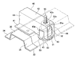
各クロスメンバ40の端部はアッパサイドフレーム32の開口35aからサイドフレーム31内に挿入され、サイドフレーム31とともにフロアフレーム19に締結されている。詳述すると、図8および図9に示すように、クロスメンバ40の端部であってサイドフレーム31内に挿入される部分には、クロスメンバ40の下壁43から側壁44、44に渡って開口45が形成されており、また、上壁42にはボルト挿通孔42aが形成されている。また、ロアサイドフレーム33には、クロスメンバ40の開口45に対向する部位に円形の孔37が設けられており、孔37の周囲はアッパサイドフレーム32側に凹む凹部38が形成されている。
The end of each
そして、ロアサイドフレーム33の下側から、段付き円筒状のカラー50が孔37に挿入されている。カラー50はアルミニウム製で、外径がクロスメンバ40の側壁44,44間寸法よりも大きい大径筒部51と側壁44,44間に挿入可能な小径筒部52が同軸上に連設され、大径筒部51の下端にフランジ部53が環状に形成されており、小径筒部52を貫通する貫通孔54を有している。大径筒部51と小径筒部52は孔37からサイドフレーム31内に挿入され、フランジ部53がロアサイドフレーム33の凹部38に当接し、溶接固定されている。大径筒部51は開口45内に挿入され、大径筒部51の上壁51aはクロスメンバ40の側壁44における開口45の上縁45aに突き当てられ、クロスメンバ40の側壁44,44間に挿入された小径筒部52の上壁52aはクロスメンバ40の上壁42の内面に突き当てられている。そして、カラー50の下側から座付きボルト55が、カラー50の貫通孔54、クロスメンバ40のボルト挿通孔42a、アッパサイドフレーム32のボルト挿通孔35bに挿通され、さらにフロアフレーム19のボルト挿通孔(図示せず)に挿通されて、フロアフレーム19に溶接固定されたナット56に螺合されている(図4参照)。これによりクロスメンバ40はカラー50によって上方に押し付けられ、クロスメンバ40の上壁42はアッパサイドフレーム32の山部35の上壁36に圧接する。
A stepped
各ボトムプレート60は、サイドフレーム31のフランジ部34およびクロスメンバ40のフランジ部41にリベット止めされている。
このように構成された燃料電池用サブフレーム30においては、アッパサイドフレーム32とロアサイドフレーム33はカラー50を介在させてクロスメンバ40の端部を挟持しており、アッパサイドフレーム32とロアサイドフレーム33とクロスメンバ40の端部は共通のボルト55によってフロアフレーム19に一体的に締結されている。
Each
In the
図7に示すように、燃料電池2,2は、燃料電池用サブフレーム30において車体前側から2本目と3本目のクロスメンバ40B,40Cの間に配置されており、図10に示すように、燃料電池2,2の下端2aをクロスメンバ40B,40Cの下端と上端の間に位置させている。そして、燃料電池2の前壁および後壁にボルト57でブラケット58,58を固定し、これらブラケット58,58をクロスメンバ40B,40Cの上壁42にボルト59で固定することによって、燃料電池2,2は燃料電池用サブフレーム30に取り付けられている。つまり、この実施例では、燃料電池2,2は、その後端部が前後輪タイヤ15A,15B間の中央近傍に配置されたクロスメンバ40Cに締結され、前後輪タイヤ15A,15B間の中央よりも車体前側に配置されており、図1に示すようにフロントシートSの下方に配置されている。
このように燃料電池2,2の下部をサブフレーム30に埋没させた構造にし、燃料電池用サブフレーム30と燃料電池2,2とを高さ方向に一部重複させて配置しているので、サブフレーム30の下面から燃料電池2,2の上面までのユニットとしての高さ寸法を低く抑えることができ、その結果、フロントフロア17の高さを低くして車両の低床化を図ることができる。
また、前述したようにサイドフレーム31の下面を湾曲させているので、車両が上に凸に湾曲した路面を走行したときにも、前後輪タイヤ15A,15B間における中央部分において路面とサイドフレーム31の下端との間に必要最小限のクリアランスを確保しつつ、車両の低床化を図ることができる。
As shown in FIG. 7, the
Since the lower part of the
Further, since the lower surface of the
高圧電装装置12,12は燃料電池2,2よりも車体前側に配置されクロスメンバ40A,40Bの間に取り付けられており、給排気デバイス10と水素循環デバイス11は燃料電池2,2よりも車体後側に配置されてクロスメンバ40D,40Eの上に取り付けられている。なお、図中符号21はマニホールドなどが配置される配管スペースである。
The high voltage
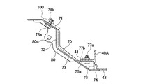
また、図3に示すように、燃料電池用サブフレーム30の直ぐ前方にはアンダーガード70が設けられている。図11はアンダーガード70の側面図であり、図12は燃料電池用サブフレーム30に取り付けられたアンダーガード70を斜め下方から見た斜視図である。
アンダーガード70はアルミニウム製で、前端側が後端側よりも上位に配置されており、概ね車体後方に進むにしたがって下方に傾斜する形状に形成されている。詳述すると、アンダーガード70は、前端側に配置されて車体後方に進むにしたがって下方に傾斜する平板状の取付フランジ部71と、取付フランジ部71の後端から鉛直下方に延びる鉛直部72と、鉛直部72の下端に連なり車体後方に進むにしたがって下方に傾斜する傾斜部73と、傾斜部73の後端から車体後方に水平に延びるオーバーハング部74とを備えて構成されており、鉛直部72と傾斜部73との接続部には補強用の複数のリブ79が車幅方向所定間隔で設けられ、傾斜部73とオーバーハング部74との接続部には、水平壁部75aを有する凹部75が車幅方向所定間隔で設けられている。また、アンダーガード70には、ラジエター14と燃料電池2との間で冷却水を循環させる冷媒配管等の配管類を挿通させるための開口76が、取付フランジ部71から傾斜部73に渡って形成されており、開口76にはその全周に亘ってリブ80が設けられ、リブ80の所定部位には冷媒配管や電気配線などを止める取り付け孔80aが設けられている。
As shown in FIG. 3, an under
The under
凹部75の水平壁部75aは最も車体前側に配置されたクロスメンバ40Aのフランジ部41の下側に配置されて、ボルト77aとナット77bによりフランジ部41に締結されており、オーバーハング部74はクロスメンバ40Aの下壁43の前端部の下側に被せられている。また、取付フランジ部71はダッシュボードの骨格を構成するロアクロス(車体フレーム)100にボルト78aとナット78bによって締結されている。すなわち、アンダーガード70の後端は最も車体の前側に配置されたクロスメンバ40Aに接続され、前端は車体フレームに接続されている。
このように燃料電池用サブフレーム30の前方にアンダーガード70を設けたことにより、車両の前進時に車体フロア下に障害物が存在した場合に、障害物をアンダーガード70によって燃料電池用サブフレーム30の下側に案内することができ、その結果、高圧電装装置12や燃料電池2などの燃料電池用サブフレーム30に搭載された機器が障害物と干渉するのを防止することができる。また、固定用のボルト77aは、傾斜部73よりも内方に凹んだ凹部75の水平壁部75aに設けているので、アンダーガード70が障害物を下方に案内する際にボルト77aの頭部が妨げになることがない。また、アンダーガード70は燃料電池用サブフレーム30の前方の限られた領域に配置するだけであるので、構造が簡単になり、軽量にできる。
The
By providing the under
また、サブフレーム30において最も車体後方側に配置されたクロスメンバ40Eは、図13,図14に示すように、2つの連結アーム22,22を介して水素タンク用サブフレーム90に連結されている。
水素タンク用サブフレーム90はアルミニウム製で、6つのポスト91,91・・・と、隣り合うポスト91,91を連結するメンバ92,92・・・とを主要構成としており、ポスト91,91・・・がフロアフレーム19の下壁19bにその下方からボルト(図示略)により締結されている。水素タンク用サブフレーム90には、中央に配置されたメンバ92よりも車体前側にキャパシタ13が取り付けられ、メンバ92よりも車体後側に水素タンク7がバンド93によって固定されている。水素タンク用サブフレーム90に搭載される機器(水素タンク7およびキャパシタ13)の総重量は、燃料電池用サブフレーム30に搭載される機器(燃料電池2,2等)の総重量よりも十分に大きく、したがって、水素タンク用サブフレーム90は燃料電池用サブフレーム30よりも機械的強度を大きく設計されている。そのため、図14に示すように、水素タンク用サブフレーム90において最も車体前側に配置されたメンバ92と燃料電池用サブフレーム30において最も車体後側に配置されたクロスメンバ40Eとを比較すると、メンバ92の方がクロスメンバ40Eよりも断面二次モーメントが極めて大きい。
Further, the
The
この実施例では、クロスメンバ40Eは、水素タンク用サブフレーム90において最も車体前方側に配置されたメンバ92に連結アーム22によって連結されている。詳述すると、図14に示すように、連結アーム22は略L字形をなし、その一端がボルト23aとナット23bによりクロスメンバ40Eの後壁に固定され、他端がボルト25aとナット25bによって、メンバ92の下壁に溶接固定された台座94に固定されている。このように燃料電池用サブフレーム30のクロスメンバ40Eを水素タンク用サブフレーム90のメンバ92に連結したことにより、クロスメンバ40Eの荷重負担を軽減することができるので、クロスメンバ40Eの強度軽減が可能になって軽量にでき、ひいては燃料電池用サブフレーム30の強度軽減および軽量化が可能になる。例えば、この実施例ではクロスメンバ40Eを他のクロスメンバ40A〜40Dと同様に閉断面形状に形成したが、クロスメンバ40Eを開断面形状にすることも可能になる。
In this embodiment, the
〔他の実施例〕
なお、この発明は前述した実施例に限られるものではない。
例えば、燃料電池用サブフレームのサイドフレームやクロスメンバの断面形状は実施例のものに限られるものではない。また、クロスメンバの数も実施例の5本に限られるものではない。
[Other Examples]
The present invention is not limited to the embodiment described above.
For example, the cross-sectional shapes of the side frames and cross members of the sub-frame for fuel cells are not limited to those of the embodiments. Further, the number of cross members is not limited to five in the embodiment.
1 燃料電池自動車
2 燃料電池
2a 下端
15A 前輪タイヤ
15B 後輪タイヤ
19 フロアフレーム
30 燃料電池用サブフレーム
31 サイドフレーム
32 アッパサイドフレーム
33 ロアサイドフレーム
40,40A〜40E クロスメンバ
55 ボルト
DESCRIPTION OF
Claims (2)
前記燃料電池用サブフレームは、車体の前後方向に延びる左右のサイドフレームと、車幅方向に延び前記左右のサイドフレームを連結する複数のクロスメンバによって構成され、
前記サイドフレームはアッパーサイドフレームとロアサイドフレームとを結合して閉断面形状に構成されており、
前記アッパーサイドフレームの車幅方向内側に形成された開口から前記クロスメンバの端部が挿入され、前記アッパーサイドフレームと前記ロアサイドフレームはカラーを介在させて前記クロスメンバの端部を挟持し、前記アッパーサイドフレームと前記ロアサイドフレームと前記クロスメンバの端部が、前記カラーを挿通する共通のボルトによって車体のフロアフレームにその下方から一体的に締結されており、
前記燃料電池は、互いに隣り合う一対の前記クロスメンバ間に配置され、該燃料電池の下端を該クロスメンバの上端と下端の間に位置させて、該燃料電池の前端部と後端部が該クロスメンバに締結されていることを特徴とする燃料電池自動車。 A fuel cell vehicle equipped with a fuel cell subframe equipped with a fuel cell that generates electricity by an electrochemical reaction between hydrogen and oxygen,
The fuel cell subframe includes left and right side frames extending in the front-rear direction of the vehicle body and a plurality of cross members extending in the vehicle width direction and connecting the left and right side frames.
The side frame is configured in a closed cross-sectional shape by combining an upper side frame and a lower side frame,
The end of the cross member is inserted from an opening formed on the inner side in the vehicle width direction of the upper side frame, and the upper side frame and the lower side frame sandwich the end of the cross member with a collar interposed therebetween, Ends of the upper side frame, the lower side frame, and the cross member are integrally fastened to the floor frame of the vehicle body from below by a common bolt that passes through the collar ,
The fuel cell is disposed between a pair of adjacent cross members, the lower end of the fuel cell is positioned between the upper end and the lower end of the cross member, and the front end and the rear end of the fuel cell are A fuel cell vehicle characterized by being fastened to a cross member.
Priority Applications (2)
| Application Number | Priority Date | Filing Date | Title |
|---|---|---|---|
| JP2005162396A JP4722569B2 (en) | 2005-06-02 | 2005-06-02 | Fuel cell vehicle |
| US11/421,248 US7641017B2 (en) | 2005-06-02 | 2006-05-31 | Fuel cell vehicle |
Applications Claiming Priority (1)
| Application Number | Priority Date | Filing Date | Title |
|---|---|---|---|
| JP2005162396A JP4722569B2 (en) | 2005-06-02 | 2005-06-02 | Fuel cell vehicle |
Publications (2)
| Publication Number | Publication Date |
|---|---|
| JP2006335215A JP2006335215A (en) | 2006-12-14 |
| JP4722569B2 true JP4722569B2 (en) | 2011-07-13 |
Family
ID=37556126
Family Applications (1)
| Application Number | Title | Priority Date | Filing Date |
|---|---|---|---|
| JP2005162396A Expired - Fee Related JP4722569B2 (en) | 2005-06-02 | 2005-06-02 | Fuel cell vehicle |
Country Status (1)
| Country | Link |
|---|---|
| JP (1) | JP4722569B2 (en) |
Families Citing this family (2)
| Publication number | Priority date | Publication date | Assignee | Title |
|---|---|---|---|---|
| JP5333980B2 (en) * | 2008-01-11 | 2013-11-06 | トヨタ自動車株式会社 | Fuel cell and its in-vehicle structure |
| JP5642650B2 (en) * | 2011-10-18 | 2014-12-17 | アイシン軽金属株式会社 | Battery-mounted structure for battery modules |
Citations (9)
| Publication number | Priority date | Publication date | Assignee | Title |
|---|---|---|---|---|
| JPS6394089U (en) * | 1986-12-04 | 1988-06-17 | ||
| JPH06263057A (en) * | 1993-03-12 | 1994-09-20 | Nissan Motor Co Ltd | Battery-mounted frame fastening structure for electric automobile |
| JPH0725247A (en) * | 1993-07-14 | 1995-01-27 | Nissan Motor Co Ltd | Battery fixing structure of electric automobile |
| JPH09300982A (en) * | 1996-05-09 | 1997-11-25 | Nissan Motor Co Ltd | Battery frame structure of electric vehicle |
| JPH09301217A (en) * | 1996-05-15 | 1997-11-25 | Nissan Motor Co Ltd | Member jointing structure for automobile |
| JP2002370550A (en) * | 2001-06-15 | 2002-12-24 | Toyota Motor Corp | High-pressure tank assembly for vehicle |
| JP2004161158A (en) * | 2002-11-14 | 2004-06-10 | Nissan Motor Co Ltd | Battery mounting structure of electric vehicle |
| JP2005079002A (en) * | 2003-09-02 | 2005-03-24 | Nissan Motor Co Ltd | Fuel cell system |
| JP2006176105A (en) * | 2004-11-26 | 2006-07-06 | Honda Motor Co Ltd | Fuel cell vehicle |
Family Cites Families (2)
| Publication number | Priority date | Publication date | Assignee | Title |
|---|---|---|---|---|
| JPH0792051B2 (en) * | 1986-10-08 | 1995-10-09 | 株式会社日立製作所 | Neutral particle injector |
| JP3904864B2 (en) * | 2001-08-28 | 2007-04-11 | 本田技研工業株式会社 | Car body rear structure |
-
2005
- 2005-06-02 JP JP2005162396A patent/JP4722569B2/en not_active Expired - Fee Related
Patent Citations (9)
| Publication number | Priority date | Publication date | Assignee | Title |
|---|---|---|---|---|
| JPS6394089U (en) * | 1986-12-04 | 1988-06-17 | ||
| JPH06263057A (en) * | 1993-03-12 | 1994-09-20 | Nissan Motor Co Ltd | Battery-mounted frame fastening structure for electric automobile |
| JPH0725247A (en) * | 1993-07-14 | 1995-01-27 | Nissan Motor Co Ltd | Battery fixing structure of electric automobile |
| JPH09300982A (en) * | 1996-05-09 | 1997-11-25 | Nissan Motor Co Ltd | Battery frame structure of electric vehicle |
| JPH09301217A (en) * | 1996-05-15 | 1997-11-25 | Nissan Motor Co Ltd | Member jointing structure for automobile |
| JP2002370550A (en) * | 2001-06-15 | 2002-12-24 | Toyota Motor Corp | High-pressure tank assembly for vehicle |
| JP2004161158A (en) * | 2002-11-14 | 2004-06-10 | Nissan Motor Co Ltd | Battery mounting structure of electric vehicle |
| JP2005079002A (en) * | 2003-09-02 | 2005-03-24 | Nissan Motor Co Ltd | Fuel cell system |
| JP2006176105A (en) * | 2004-11-26 | 2006-07-06 | Honda Motor Co Ltd | Fuel cell vehicle |
Also Published As
| Publication number | Publication date |
|---|---|
| JP2006335215A (en) | 2006-12-14 |
Similar Documents
| Publication | Publication Date | Title |
|---|---|---|
| US7641017B2 (en) | Fuel cell vehicle | |
| US7896115B2 (en) | Fuel cell vehicle | |
| JP4727323B2 (en) | Fuel cell vehicle structure | |
| US7726429B2 (en) | Fuel cell vehicle having support frame which couples side frames in width direction of vehicle | |
| US10688854B2 (en) | Electric vehicle with integrated battery and floor assembly | |
| US7614473B2 (en) | Vehicle body structure | |
| US9260034B2 (en) | Fuel cell power plant provided in vehicle | |
| JP4494333B2 (en) | Fuel cell vehicle | |
| US9283838B2 (en) | Fuel cell system protection in a vehicle | |
| JP5187820B2 (en) | Upper body structure for fuel cell vehicles for reinforcing floor kick-up | |
| KR101808384B1 (en) | Vehicle | |
| JP4637666B2 (en) | Fuel cell vehicle | |
| JP2009057035A (en) | Chassis frame for fuel cell vehicle | |
| US20200047808A1 (en) | Vehicle underbody structure | |
| JP2006335212A (en) | Fuel cell automobile | |
| JP4503503B2 (en) | Fuel cell vehicle | |
| KR100674688B1 (en) | Motor vehicle mounted with fuel cell | |
| JP4722569B2 (en) | Fuel cell vehicle | |
| JP2005212513A (en) | Vehicle mounting structure of fuel cell system | |
| JP4503501B2 (en) | Fuel cell vehicle | |
| US10355293B2 (en) | Fuel cell vehicle | |
| JP2007015615A (en) | Fuel cell vehicle structure | |
| JP7238550B2 (en) | fuel cell vehicle | |
| JP2007015613A (en) | Fuel cell vehicle structure | |
| JP2006335214A (en) | Fuel cell electric automobile |
Legal Events
| Date | Code | Title | Description |
|---|---|---|---|
| A621 | Written request for application examination |
Free format text: JAPANESE INTERMEDIATE CODE: A621 Effective date: 20071129 |
|
| A977 | Report on retrieval |
Free format text: JAPANESE INTERMEDIATE CODE: A971007 Effective date: 20100728 |
|
| A131 | Notification of reasons for refusal |
Free format text: JAPANESE INTERMEDIATE CODE: A131 Effective date: 20100803 |
|
| A521 | Request for written amendment filed |
Free format text: JAPANESE INTERMEDIATE CODE: A523 Effective date: 20100915 |
|
| TRDD | Decision of grant or rejection written | ||
| A01 | Written decision to grant a patent or to grant a registration (utility model) |
Free format text: JAPANESE INTERMEDIATE CODE: A01 Effective date: 20110329 |
|
| A01 | Written decision to grant a patent or to grant a registration (utility model) |
Free format text: JAPANESE INTERMEDIATE CODE: A01 |
|
| A61 | First payment of annual fees (during grant procedure) |
Free format text: JAPANESE INTERMEDIATE CODE: A61 Effective date: 20110406 |
|
| FPAY | Renewal fee payment (event date is renewal date of database) |
Free format text: PAYMENT UNTIL: 20140415 Year of fee payment: 3 |
|
| R150 | Certificate of patent or registration of utility model |
Free format text: JAPANESE INTERMEDIATE CODE: R150 |
|
| LAPS | Cancellation because of no payment of annual fees |