JP4718100B2 - Camera system having at least two first and second cameras - Google Patents
Camera system having at least two first and second cameras Download PDFInfo
- Publication number
- JP4718100B2 JP4718100B2 JP2002512740A JP2002512740A JP4718100B2 JP 4718100 B2 JP4718100 B2 JP 4718100B2 JP 2002512740 A JP2002512740 A JP 2002512740A JP 2002512740 A JP2002512740 A JP 2002512740A JP 4718100 B2 JP4718100 B2 JP 4718100B2
- Authority
- JP
- Japan
- Prior art keywords
- cameras
- camera
- camera system
- respect
- symmetry axis
- Prior art date
- Legal status (The legal status is an assumption and is not a legal conclusion. Google has not performed a legal analysis and makes no representation as to the accuracy of the status listed.)
- Expired - Lifetime
Links
Images

Classifications
-
- G—PHYSICS
- G01—MEASURING; TESTING
- G01C—MEASURING DISTANCES, LEVELS OR BEARINGS; SURVEYING; NAVIGATION; GYROSCOPIC INSTRUMENTS; PHOTOGRAMMETRY OR VIDEOGRAMMETRY
- G01C11/00—Photogrammetry or videogrammetry, e.g. stereogrammetry; Photographic surveying
- G01C11/02—Picture taking arrangements specially adapted for photogrammetry or photographic surveying, e.g. controlling overlapping of pictures
-
- G—PHYSICS
- G03—PHOTOGRAPHY; CINEMATOGRAPHY; ANALOGOUS TECHNIQUES USING WAVES OTHER THAN OPTICAL WAVES; ELECTROGRAPHY; HOLOGRAPHY
- G03B—APPARATUS OR ARRANGEMENTS FOR TAKING PHOTOGRAPHS OR FOR PROJECTING OR VIEWING THEM; APPARATUS OR ARRANGEMENTS EMPLOYING ANALOGOUS TECHNIQUES USING WAVES OTHER THAN OPTICAL WAVES; ACCESSORIES THEREFOR
- G03B37/00—Panoramic or wide-screen photography; Photographing extended surfaces, e.g. for surveying; Photographing internal surfaces, e.g. of pipe
- G03B37/04—Panoramic or wide-screen photography; Photographing extended surfaces, e.g. for surveying; Photographing internal surfaces, e.g. of pipe with cameras or projectors providing touching or overlapping fields of view
Abstract
Description
【0001】
本発明は写真測定並びに空中偵察に用いられるカメラシステムに関する。
【0002】
写真測定にも、空中偵察にもデジタルカメラを使用することが増加している。この場合、撮影された画像の高い位置解像度が望まれる一方、色情報の記録も望まれる。最高の位置解像度は現在、最終的には白黒情報の記録だけが可能なパンクロカメラによって得られる。
【0003】
さらに飛行機内のカメラシステム全体を設けるのに使用できる空間は限られているので、複数のカメラをコンパクトに配置することが望まれる。
【0004】
このような要望を本発明は、独立請求項の特徴部分に記載された構成を有するカメラシステムによって満たす。本発明の有利な構成は従属請求項の特徴部分に記載されている。
【0005】
本発明のカメラシステムは、独自のレンズを1つずつ有する少なくとも2つの第1のカメラを有している。これらのレンズの光軸は相互に傾斜して配置されている。さらにこのカメラシステムは少なくとも2つの別のカメラを有する。これらのカメラは第1カメラとオフセットして第1カメラの視野方向に配置される。
【0006】
第1カメラのレンズの光軸が相互に傾斜して配置され、従って交差することによって、第1カメラの開口錐を囲む外縁は極めて小さい幅の領域を有するようになる。有利にはこのような狭幅領域(Einschnuerung)に第2カメラが配置される。
【0007】
さらに有利な実施例では、少なくとも3つの第1カメラが対称軸に対して対称に配置され、第2カメラはこの対称軸の方向に第1カメラとずらして配置される。
【0008】
特に有利には、全部で4つの第1カメラが対称軸に対して対称に配置される。この4つのカメラによって高い画像カバー度(Bildabdeckung)が得られる。すなわち同時に検出される大きな角度領域が得られる。
【0009】
ここで第1カメラはパンクロデジタルカメラであり、このカメラによって、測定されるべき地帯がラテラル方向での高い解像度で撮影される。しかし色情報はない。この場合、第2カメラは多色性デジタルカメラとして構成され、この第2カメラによって上空を飛行する地帯の色情報も記録される。しかしラテラル方向の解像度はより低い。
【0010】
さらに有利には4つの第2カメラを設けることもできる。この第2カメラは同じように第1カメラの対称軸に対して対称に配置される。第2カメラの光軸はここで相互に平行に配向される。
【0011】
このカメラシステムによって記録された画像情報の、後の写真測定的な評価のために、第1カメラと第2カメラの全体の開口錐は共通の、中央のオーバーラップ領域を有する。
【0012】
本発明のさらなる細部を以下で図示された実施例に基づきより詳細に説明する。
【0013】
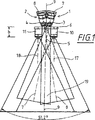
図1には本発明によるカメラシステムの断面図が示されており、
図2には図1のカメラシステムの斜視図が示されている。
【0014】
図1および図2に示されたカメラシステムは、4つの第1カメラ(1, 2, 12, 13)と4つの第2カメラ(10, 11, 14)を有する。ここで第2カメラ(10, 11, 14)は、第1カメラ(1, 2, 12, 13)の視野方向に第1カメラ(1, 2, 12, 13)に対してずらして配置される。ここでこれらの4つの第1カメラと第2カメラの各カメラはケーシングと、各ケーシングに収容されたレンズと、各レンズの後方に配置されたCCD画像センサを有する。ここで第1カメラ(1, 2, 12, 13)の図示されていない画像センサは、高いラテラル方向の解像度を有するパンクロCCD画像センサとして構成される。第2カメラ(14, 15, 16)のCCDセンサは、高解像度のカラーカメラチップとして構成される。
【0015】
カメラシステム全体は、第1カメラのうちの1つのカメラ(12)によって隠されているので、図2の斜視図には示されていない、さらなる4番目の第2カメラを有していることをここで指摘しておく。
【0016】
4つの第1カメラ(1, 2, 12, 13)は対称軸(9)に対して対称に配置される。ここでこれらの第1カメラ(1, 2, 12, 13)は相互に、対称軸(9)に関して対称に同じ角度値だけ傾斜して相互に配置される。これによって第1カメラの光軸(7, 8)は、対称軸(9)上に位置する共通の交点(5)で交差する。
【0017】
第1カメラ(1, 2)を相互に傾斜して配置することによって第1カメラのレンズ(3, 4)の直前に、第1カメラの開口錐を包囲する外縁が、ラテラル方向すなわち対称軸(9)に対して垂直な方向で狭幅部分を有する領域(b)が設けられる。この領域(b)で第1カメラ(1, 2)の開口錐の外縁の直径は一定である。第1カメラ(1, 2)の開口錐の外縁が本質的に一定の直径を有するこの領域に第2カメラ(10, 11)が次のように配置される。すなわち第2カメラ(10, 11)のケーシングによって第1カメラ(1, 2)の開口錐が制限されないように配置される。このため第2カメラ(10, 11)に対する支持構造体(6)は、第1カメラの開口錐が自由に透過するのに相応の大きさの開口部(Oeffnung)を有する。
【0018】
第2カメラ(10, 11)の光軸(17, 18)は対称軸(9)に対して平行に配向される。
【0019】
中央領域(19)では第1カメラ(1, 2)の全体の開口錐と第2カメラ(10, 11)の全体の開口錐がオーバーラップする。
【0020】
第1カメラのレンズ(3, 4)は、各第1カメラが少なくとも20°の画角を有するように配置される。第1カメラの相対的な傾斜は相互に次のように選択される。すなわち全第1カメラが合わせて40°以上の画角を、相互に垂直な2つの方向で対称軸(9)に対して垂直に検出するように選択される。
【0021】
第2カメラ(10, 11)のレンズは、全第2カメラが合わせて50°以上の画角を、相互に垂直な2つの方向で対称軸(9)に対して垂直に検出するように選択される。
【0022】
本発明のカメラシステムによって、個々のカメラを最適にコンパクトに配置することができる。ここで第1カメラの統合された視野も、第2カメラの統合された視野も完全に地上をカバーすることを保証する。すなわち個々の開口錐の間に検出されない角度領域は存在しない。
【0023】
コンパクトな構成方法と、これによって必要な面積が低減することによって本発明のカメラの配置は、振動および温度特性に関する高い安定性も保証する。これは個々のカメラ間の間隔が小さいことの結果である。
【0024】
示された配置では、第1カメラ間の相互の間隔は第2カメラ間の相互の間隔より大きい。
【図面の簡単な説明】
【図1】 本発明によるカメラシステムの断面図である。
【図2】 図1のカメラシステムの斜視図である。[0001]
The present invention relates to a camera system used for photo measurement and aerial reconnaissance.
[0002]
The use of digital cameras for both photo measurement and aerial reconnaissance is increasing. In this case, high positional resolution of the photographed image is desired, while recording of color information is also desired. The highest position resolution is currently obtained by a panchromatic camera that can ultimately only record black and white information.
[0003]
Furthermore, since the space that can be used to provide the entire camera system in the airplane is limited, it is desirable to arrange a plurality of cameras in a compact manner.
[0004]
This need is met by a camera system having the structure described in the characterizing part of the independent claims. Advantageous configurations of the invention are described in the characterizing parts of the dependent claims.
[0005]
The camera system of the present invention has at least two first cameras each having its own lens. The optical axes of these lenses are arranged so as to be inclined with respect to each other. Furthermore, the camera system has at least two separate cameras. These cameras are arranged in viewing field direction of the first camera and the first camera and the offset.
[0006]
The optical axis of the first camera lens is disposed inclined to each other, thus by intersecting the outer edge surrounding the opening cone of the first camera will have a region of very small width. The second camera is preferably arranged in such a narrow area.
[0007]
In a further advantageous embodiment, at least three first cameras are arranged symmetrically with respect to the axis of symmetry and the second camera is arranged offset from the first camera in the direction of this axis of symmetry.
[0008]
Particularly preferably, a total of four first cameras are arranged symmetrically with respect to the symmetry axis. High image coverage (Bildabdeckung) can be obtained by these four cameras. That is, a large angle region that is detected simultaneously is obtained.
[0009]
Here, the first camera is a panchromatic digital camera, and a zone to be measured is photographed with a high resolution in the lateral direction by this camera. But there is no color information. In this case, the second camera is configured as a pleochroic digital camera, and color information of a zone flying over the sky is also recorded by the second camera. However, the lateral resolution is lower.
[0010]
More advantageously, four second cameras can also be provided. This second camera is likewise arranged symmetrically with respect to the symmetry axis of the first camera. The optical axes of the second camera are now oriented parallel to each other.
[0011]
For later photometric evaluation of the image information recorded by this camera system, the entire aperture cone of the first camera and the second camera has a common, central overlap region.
[0012]
Further details of the invention are explained in more detail below on the basis of the illustrated embodiment.
[0013]
FIG. 1 shows a cross-sectional view of a camera system according to the present invention.
FIG. 2 is a perspective view of the camera system of FIG.
[0014]
The camera system shown in FIGS. 1 and 2 has four first cameras (1, 2, 12, 13) and four second cameras (10, 11, 14). Wherein the second camera (10, 11, 14) are arranged offset relative to the first camera (1, 2, 12, 13) the first camera in the viewing field direction (1, 2, 12, 13) The Here, each of these four first and second cameras has a casing, a lens housed in each casing, and a CCD image sensor disposed behind each lens. Here, an image sensor (not shown) of the first camera (1, 2, 12, 13) is configured as a panchromatic CCD image sensor having a high lateral resolution. The CCD sensor of the second camera (14, 15, 16) is configured as a high-resolution color camera chip.
[0015]
Since the entire camera system is hidden by one camera (12) of the first cameras, it has an additional fourth second camera not shown in the perspective view of FIG. I will point out here.
[0016]
The four first cameras (1, 2, 12, 13) are arranged symmetrically with respect to the symmetry axis (9). Here, these first cameras (1, 2, 12, 13) are arranged mutually tilted symmetrically with respect to the symmetry axis (9) by the same angle value. Thereby, the optical axes (7, 8) of the first camera intersect at a common intersection (5) located on the symmetry axis (9).
[0017]
Immediately before the first camera (1, 2) first camera lens by placing inclined to each other (3, 4), an outer edge surrounding the opening cone of the first camera, the lateral direction, that is axis of symmetry ( A region (b) having a narrow portion in a direction perpendicular to 9) is provided. In this region (b), the diameter of the outer edge of the aperture cone of the first camera (1, 2) is constant. The second camera (10, 11) is arranged in this area in this region where the outer edge of the aperture cone of the first camera (1, 2) has an essentially constant diameter. That is, it arrange | positions so that the opening cone of a 1st camera (1, 2) may not be restrict | limited by the casing of a 2nd camera (10, 11). For this reason, the support structure (6) for the second camera (10, 11) has an opening (Oeffnung) of an appropriate size so that the aperture cone of the first camera can pass through freely.
[0018]
The optical axes (17, 18) of the second camera (10, 11) are oriented parallel to the axis of symmetry (9).
[0019]
Entire aperture cone of the central region (19) first camera (1, 2) the whole of the opening cone and the second camera (10, 11) overlap.
[0020]
The lenses (3,4) of the first camera are arranged so that each first camera has an angle of view of at least 20 °. The relative tilts of the first cameras are selected as follows. That is, all the first cameras are selected so that the angle of view of 40 ° or more is detected perpendicularly to the symmetry axis (9) in two directions perpendicular to each other.
[0021]
The lenses of the second camera (10, 11) are selected so that all the second cameras can detect the angle of view of 50 ° or more perpendicular to the symmetry axis (9) in two directions perpendicular to each other. Is done.
[0022]
With the camera system of the present invention, individual cameras can be optimally compactly arranged. Here it is ensured that both the integrated view of the first camera and the integrated view of the second camera completely cover the ground. That is, there is no angular region that is not detected between individual aperture cones .
[0023]
Due to the compact construction method and thereby reducing the required area, the arrangement of the camera according to the invention also guarantees high stability with respect to vibration and temperature characteristics. This is a result of the small spacing between the individual cameras.
[0024]
In the arrangement shown, the mutual spacing between the first cameras is greater than the mutual spacing between the second cameras.
[Brief description of the drawings]
FIG. 1 is a cross-sectional view of a camera system according to the present invention.
FIG. 2 is a perspective view of the camera system of FIG.
Claims (9)
前記少なくとも2つの第1カメラは、光軸が相互に傾斜して配置されている独自のレンズを1つずつ有しており、
前記少なくとも2つの第2カメラは、前記第1カメラの視野方向の方向に、当該第1カメラと間隔を空けて配置されており、
前記複数の第2カメラは次のような領域に配置されている、すなわち、前記複数の第1カメラの開口錐を包囲する外縁が狭幅部分または一定直径領域を有する領域に配置されている、
ことを特徴とするカメラシステム。A camera system having at least two first cameras and at least two second cameras,
Each of the at least two first cameras has a unique lens arranged so that the optical axes are inclined with respect to each other.
Said at least two second cameras in the direction of the viewing field direction of the first camera, which is arranged at the first camera and the distance,
The plurality of second cameras are arranged in the following areas, that is, the outer edges that surround the aperture cones of the plurality of first cameras are arranged in areas having a narrow width portion or a constant diameter area.
A camera system characterized by that.
Applications Claiming Priority (3)
| Application Number | Priority Date | Filing Date | Title |
|---|---|---|---|
| DE10034601A DE10034601B4 (en) | 2000-07-14 | 2000-07-14 | Camera system with at least two first and second cameras |
| DE10034601.4 | 2000-07-14 | ||
| PCT/EP2001/007693 WO2002006892A2 (en) | 2000-07-14 | 2001-07-05 | Camera system with at least two first and second cameras |
Publications (2)
| Publication Number | Publication Date |
|---|---|
| JP2004504631A JP2004504631A (en) | 2004-02-12 |
| JP4718100B2 true JP4718100B2 (en) | 2011-07-06 |
Family
ID=7649139
Family Applications (1)
| Application Number | Title | Priority Date | Filing Date |
|---|---|---|---|
| JP2002512740A Expired - Lifetime JP4718100B2 (en) | 2000-07-14 | 2001-07-05 | Camera system having at least two first and second cameras |
Country Status (7)
| Country | Link |
|---|---|
| US (1) | US6834163B2 (en) |
| EP (1) | EP1301825B1 (en) |
| JP (1) | JP4718100B2 (en) |
| AT (1) | ATE357681T1 (en) |
| DE (2) | DE10034601B4 (en) |
| ES (1) | ES2284687T3 (en) |
| WO (1) | WO2002006892A2 (en) |
Families Citing this family (32)
| Publication number | Priority date | Publication date | Assignee | Title |
|---|---|---|---|---|
| US20030048357A1 (en) * | 2001-08-29 | 2003-03-13 | Geovantage, Inc. | Digital imaging system for airborne applications |
| US20040257441A1 (en) * | 2001-08-29 | 2004-12-23 | Geovantage, Inc. | Digital imaging system for airborne applications |
| US7725258B2 (en) | 2002-09-20 | 2010-05-25 | M7 Visual Intelligence, L.P. | Vehicle based data collection and processing system and imaging sensor system and methods thereof |
| US8483960B2 (en) | 2002-09-20 | 2013-07-09 | Visual Intelligence, LP | Self-calibrated, remote imaging and data processing system |
| US7127348B2 (en) | 2002-09-20 | 2006-10-24 | M7 Visual Intelligence, Lp | Vehicle based data collection and processing system |
| US7893957B2 (en) * | 2002-08-28 | 2011-02-22 | Visual Intelligence, LP | Retinal array compound camera system |
| US8994822B2 (en) | 2002-08-28 | 2015-03-31 | Visual Intelligence Lp | Infrastructure mapping system and method |
| USRE49105E1 (en) | 2002-09-20 | 2022-06-14 | Vi Technologies, Llc | Self-calibrated, remote imaging and data processing system |
| US7365774B2 (en) | 2002-12-13 | 2008-04-29 | Pierre Louis | Device with camera modules and flying apparatus provided with such a device |
| US9182228B2 (en) | 2006-02-13 | 2015-11-10 | Sony Corporation | Multi-lens array system and method |
| US20080100711A1 (en) * | 2006-10-26 | 2008-05-01 | Wisted Jeffrey M | Integrated Multiple Imaging Device |
| US8675068B2 (en) | 2008-04-11 | 2014-03-18 | Nearmap Australia Pty Ltd | Systems and methods of capturing large area images in detail including cascaded cameras and/or calibration features |
| US8497905B2 (en) | 2008-04-11 | 2013-07-30 | nearmap australia pty ltd. | Systems and methods of capturing large area images in detail including cascaded cameras and/or calibration features |
| DE102008045242B4 (en) * | 2008-08-28 | 2012-11-08 | Deutsches Zentrum für Luft- und Raumfahrt e.V. | Sensor arrangement for the indirect generation of high-resolution multispectral images |
| US7929852B1 (en) * | 2009-10-13 | 2011-04-19 | Vincent Pace | Integrated 2D/3D camera |
| ES2359797B1 (en) * | 2009-11-17 | 2012-03-30 | Simulacions Òptiques, S.L. | PHOTOMETRIC DEVICE ELECTRO-OPTICAL DYNAMIC AND ITS PROCEDURE FOR THE DYNAMIC MEASUREMENT OF THE AMOUNT AND DISTRIBUTION OF POLYCHROMEDIC LIGHT. |
| US8542286B2 (en) * | 2009-11-24 | 2013-09-24 | Microsoft Corporation | Large format digital camera with multiple optical systems and detector arrays |
| US8665316B2 (en) * | 2009-11-24 | 2014-03-04 | Microsoft Corporation | Multi-resolution digital large format camera with multiple detector arrays |
| DE102010041569B4 (en) * | 2010-09-28 | 2017-04-06 | Leica Geosystems Ag | Digital camera system, color filter element for digital camera system, method for determining deviations between the cameras of a digital camera system and image processing unit for digital camera system |
| US8548313B2 (en) | 2010-09-30 | 2013-10-01 | Trimble Germany Gmbh | Aerial digital camera and method of controlling the same |
| US8879902B2 (en) | 2010-10-08 | 2014-11-04 | Vincent Pace & James Cameron | Integrated 2D/3D camera with fixed imaging parameters |
| US9071738B2 (en) | 2010-10-08 | 2015-06-30 | Vincent Pace | Integrated broadcast and auxiliary camera system |
| CN102261909B (en) * | 2011-04-20 | 2012-10-03 | 中国科学院光电技术研究所 | Spliced large area array digital aerial camera |
| ES2535205B1 (en) * | 2013-11-04 | 2016-02-24 | Universidad De Salamanca | Photogrammetric platform |
| US9046759B1 (en) * | 2014-06-20 | 2015-06-02 | nearmap australia pty ltd. | Compact multi-resolution aerial camera system |
| US9440750B2 (en) | 2014-06-20 | 2016-09-13 | nearmap australia pty ltd. | Wide-area aerial camera systems |
| US9641736B2 (en) | 2014-06-20 | 2017-05-02 | nearmap australia pty ltd. | Wide-area aerial camera systems |
| US9185290B1 (en) | 2014-06-20 | 2015-11-10 | Nearmap Australia Pty Ltd | Wide-area aerial camera systems |
| US9052571B1 (en) | 2014-06-20 | 2015-06-09 | nearmap australia pty ltd. | Wide-area aerial camera systems |
| US9918009B2 (en) * | 2015-08-03 | 2018-03-13 | GE Lighting Solutions, LLC | Method and system for imaging in a luminaire |
| DE102017114962B4 (en) * | 2017-07-05 | 2019-08-29 | Dallmeier Electronic Gmbh & Co. Kg | Multi-sensor camera |
| CN108827246A (en) * | 2018-03-20 | 2018-11-16 | 哈尔滨工程大学 | A kind of binocular vision device that can accurately adjust |
Citations (4)
| Publication number | Priority date | Publication date | Assignee | Title |
|---|---|---|---|---|
| JPH0330680U (en) * | 1989-08-03 | 1991-03-26 | ||
| JPH0511332A (en) * | 1991-07-04 | 1993-01-22 | Canon Inc | Photographing device |
| JPH09269549A (en) * | 1996-03-29 | 1997-10-14 | Nec Corp | Image pickup device for artificial satellite and its image pickup method |
| JPH1146325A (en) * | 1997-07-25 | 1999-02-16 | Tec Corp | Panorama image-pickup device |
Family Cites Families (10)
| Publication number | Priority date | Publication date | Assignee | Title |
|---|---|---|---|---|
| DE299786C (en) * | ||||
| US891013A (en) * | 1907-01-25 | 1908-06-16 | John Hammond Smith | Method of reproducing objects. |
| US1797849A (en) * | 1926-12-16 | 1931-03-24 | Firm Photogrammetrie G M B H | Multiple chamber for taking photographs from aeroplanes |
| US1735109A (en) * | 1927-02-08 | 1929-11-12 | Leon T Eliel | Process of and apparatus for making aerial photographs |
| US3518929A (en) * | 1967-03-06 | 1970-07-07 | Gen Electric | Three dimensional camera |
| DE3717906A1 (en) * | 1987-05-27 | 1988-12-08 | Zeiss Carl Fa | WIDE-ANGLE WATCHING WINDOW |
| US5016109A (en) * | 1990-07-02 | 1991-05-14 | Bell South Corporation | Apparatus and method for segmenting a field of view into contiguous, non-overlapping, vertical and horizontal sub-fields |
| EP0631250B1 (en) * | 1993-06-21 | 2002-03-20 | Nippon Telegraph And Telephone Corporation | Method and apparatus for reconstructing three-dimensional objects |
| DE4420422C2 (en) * | 1994-06-10 | 1997-09-18 | Dickmanns Ernst Dieter Prof Dr | Technical complex eye for dynamic machine vision |
| US6195204B1 (en) * | 1998-08-28 | 2001-02-27 | Lucent Technologies Inc. | Compact high resolution panoramic viewing system |
-
2000
- 2000-07-14 DE DE10034601A patent/DE10034601B4/en not_active Expired - Lifetime
-
2001
- 2001-07-05 WO PCT/EP2001/007693 patent/WO2002006892A2/en active IP Right Grant
- 2001-07-05 AT AT01969338T patent/ATE357681T1/en active
- 2001-07-05 DE DE50112235T patent/DE50112235D1/en not_active Expired - Lifetime
- 2001-07-05 ES ES01969338T patent/ES2284687T3/en not_active Expired - Lifetime
- 2001-07-05 JP JP2002512740A patent/JP4718100B2/en not_active Expired - Lifetime
- 2001-07-05 EP EP01969338A patent/EP1301825B1/en not_active Expired - Lifetime
-
2003
- 2003-01-14 US US10/341,454 patent/US6834163B2/en not_active Expired - Lifetime
Patent Citations (4)
| Publication number | Priority date | Publication date | Assignee | Title |
|---|---|---|---|---|
| JPH0330680U (en) * | 1989-08-03 | 1991-03-26 | ||
| JPH0511332A (en) * | 1991-07-04 | 1993-01-22 | Canon Inc | Photographing device |
| JPH09269549A (en) * | 1996-03-29 | 1997-10-14 | Nec Corp | Image pickup device for artificial satellite and its image pickup method |
| JPH1146325A (en) * | 1997-07-25 | 1999-02-16 | Tec Corp | Panorama image-pickup device |
Also Published As
| Publication number | Publication date |
|---|---|
| JP2004504631A (en) | 2004-02-12 |
| ATE357681T1 (en) | 2007-04-15 |
| US6834163B2 (en) | 2004-12-21 |
| DE50112235D1 (en) | 2007-05-03 |
| WO2002006892A2 (en) | 2002-01-24 |
| WO2002006892A3 (en) | 2002-04-11 |
| DE10034601A1 (en) | 2002-01-24 |
| ES2284687T3 (en) | 2007-11-16 |
| EP1301825A2 (en) | 2003-04-16 |
| US20030138247A1 (en) | 2003-07-24 |
| DE10034601B4 (en) | 2013-05-23 |
| EP1301825B1 (en) | 2007-03-21 |
Similar Documents
| Publication | Publication Date | Title |
|---|---|---|
| JP4718100B2 (en) | Camera system having at least two first and second cameras | |
| US9407851B2 (en) | CMOS image sensors for hardwired image processing | |
| EP2619987B1 (en) | Wide angle field of view active illumination imaging system | |
| Mikhail et al. | Introduction to modern photogrammetry | |
| Schenk | Introduction to photogrammetry | |
| JP5731529B2 (en) | Multi-resolution digital large format camera with multiple detector arrays | |
| US7176960B1 (en) | System and methods for generating spherical mosaic images | |
| JP2001523929A (en) | Optoelectronic camera and method for formatting images with it | |
| JP5806225B2 (en) | Large format digital camera with multiple optical systems and detector array | |
| US20050068632A1 (en) | High resolution multi-lens imaging device | |
| US20110018964A1 (en) | Systems and methods for panoramic imaging | |
| JP2013534379A (en) | Image capture device and image capture method | |
| JPH05336423A (en) | Digital face-like camera provided with multiple optical system | |
| JP2001141423A (en) | Image pickup device and image processor | |
| US7116351B2 (en) | Imaging device | |
| US20230152672A1 (en) | Mounting systems for multi-camera imagers | |
| JP2005283616A (en) | Imaging apparatus | |
| US6580557B2 (en) | Single lens instantaneous 3D image taking device | |
| US7949241B2 (en) | Anamorphic focal array | |
| JP2016048824A (en) | Tracking device, tracking system and display device | |
| WO2021163071A1 (en) | Panoramic camera system for enhanced sensing | |
| JP4781537B2 (en) | Camera system and display device | |
| JP2001320736A (en) | All-around stereoscopic camera | |
| JP2019117243A (en) | Imaging device | |
| CN214010301U (en) | Digital aerial photography suite |
Legal Events
| Date | Code | Title | Description |
|---|---|---|---|
| A711 | Notification of change in applicant |
Free format text: JAPANESE INTERMEDIATE CODE: A712 Effective date: 20080118 |
|
| A521 | Request for written amendment filed |
Free format text: JAPANESE INTERMEDIATE CODE: A821 Effective date: 20080118 |
|
| A621 | Written request for application examination |
Free format text: JAPANESE INTERMEDIATE CODE: A621 Effective date: 20080507 |
|
| A131 | Notification of reasons for refusal |
Free format text: JAPANESE INTERMEDIATE CODE: A131 Effective date: 20100617 |
|
| A601 | Written request for extension of time |
Free format text: JAPANESE INTERMEDIATE CODE: A601 Effective date: 20100914 |
|
| A602 | Written permission of extension of time |
Free format text: JAPANESE INTERMEDIATE CODE: A602 Effective date: 20100922 |
|
| A521 | Request for written amendment filed |
Free format text: JAPANESE INTERMEDIATE CODE: A523 Effective date: 20101213 |
|
| RD04 | Notification of resignation of power of attorney |
Free format text: JAPANESE INTERMEDIATE CODE: A7424 Effective date: 20101227 |
|
| RD04 | Notification of resignation of power of attorney |
Free format text: JAPANESE INTERMEDIATE CODE: A7424 Effective date: 20101228 |
|
| TRDD | Decision of grant or rejection written | ||
| A01 | Written decision to grant a patent or to grant a registration (utility model) |
Free format text: JAPANESE INTERMEDIATE CODE: A01 Effective date: 20110323 |
|
| A01 | Written decision to grant a patent or to grant a registration (utility model) |
Free format text: JAPANESE INTERMEDIATE CODE: A01 |
|
| A61 | First payment of annual fees (during grant procedure) |
Free format text: JAPANESE INTERMEDIATE CODE: A61 Effective date: 20110331 |
|
| R150 | Certificate of patent or registration of utility model |
Ref document number: 4718100 Country of ref document: JP Free format text: JAPANESE INTERMEDIATE CODE: R150 Free format text: JAPANESE INTERMEDIATE CODE: R150 |
|
| FPAY | Renewal fee payment (event date is renewal date of database) |
Free format text: PAYMENT UNTIL: 20140408 Year of fee payment: 3 |
|
| FPAY | Renewal fee payment (event date is renewal date of database) |
Free format text: PAYMENT UNTIL: 20140408 Year of fee payment: 3 |
|
| S111 | Request for change of ownership or part of ownership |
Free format text: JAPANESE INTERMEDIATE CODE: R313113 |
|
| FPAY | Renewal fee payment (event date is renewal date of database) |
Free format text: PAYMENT UNTIL: 20140408 Year of fee payment: 3 |
|
| R360 | Written notification for declining of transfer of rights |
Free format text: JAPANESE INTERMEDIATE CODE: R360 |
|
| FPAY | Renewal fee payment (event date is renewal date of database) |
Free format text: PAYMENT UNTIL: 20140408 Year of fee payment: 3 |
|
| R360 | Written notification for declining of transfer of rights |
Free format text: JAPANESE INTERMEDIATE CODE: R360 |
|
| R371 | Transfer withdrawn |
Free format text: JAPANESE INTERMEDIATE CODE: R371 |
|
| FPAY | Renewal fee payment (event date is renewal date of database) |
Free format text: PAYMENT UNTIL: 20140408 Year of fee payment: 3 |
|
| S111 | Request for change of ownership or part of ownership |
Free format text: JAPANESE INTERMEDIATE CODE: R313113 |
|
| FPAY | Renewal fee payment (event date is renewal date of database) |
Free format text: PAYMENT UNTIL: 20140408 Year of fee payment: 3 |
|
| R350 | Written notification of registration of transfer |
Free format text: JAPANESE INTERMEDIATE CODE: R350 |
|
| R250 | Receipt of annual fees |
Free format text: JAPANESE INTERMEDIATE CODE: R250 |
|
| R250 | Receipt of annual fees |
Free format text: JAPANESE INTERMEDIATE CODE: R250 |
|
| R250 | Receipt of annual fees |
Free format text: JAPANESE INTERMEDIATE CODE: R250 |
|
| R250 | Receipt of annual fees |
Free format text: JAPANESE INTERMEDIATE CODE: R250 |
|
| R250 | Receipt of annual fees |
Free format text: JAPANESE INTERMEDIATE CODE: R250 |
|
| R250 | Receipt of annual fees |
Free format text: JAPANESE INTERMEDIATE CODE: R250 |
|
| R250 | Receipt of annual fees |
Free format text: JAPANESE INTERMEDIATE CODE: R250 |
|
| R250 | Receipt of annual fees |
Free format text: JAPANESE INTERMEDIATE CODE: R250 |
|
| EXPY | Cancellation because of completion of term |