JP4717000B2 - Texture-based method and system for line and character anti-aliasing - Google Patents
Texture-based method and system for line and character anti-aliasing Download PDFInfo
- Publication number
- JP4717000B2 JP4717000B2 JP2006533344A JP2006533344A JP4717000B2 JP 4717000 B2 JP4717000 B2 JP 4717000B2 JP 2006533344 A JP2006533344 A JP 2006533344A JP 2006533344 A JP2006533344 A JP 2006533344A JP 4717000 B2 JP4717000 B2 JP 4717000B2
- Authority
- JP
- Japan
- Prior art keywords
- line
- texture
- texture map
- luminance
- character
- Prior art date
- Legal status (The legal status is an assumption and is not a legal conclusion. Google has not performed a legal analysis and makes no representation as to the accuracy of the status listed.)
- Expired - Fee Related
Links
Images


Classifications
-
- G—PHYSICS
- G06—COMPUTING; CALCULATING OR COUNTING
- G06F—ELECTRIC DIGITAL DATA PROCESSING
- G06F3/00—Input arrangements for transferring data to be processed into a form capable of being handled by the computer; Output arrangements for transferring data from processing unit to output unit, e.g. interface arrangements
- G06F3/14—Digital output to display device ; Cooperation and interconnection of the display device with other functional units
-
- G—PHYSICS
- G06—COMPUTING; CALCULATING OR COUNTING
- G06T—IMAGE DATA PROCESSING OR GENERATION, IN GENERAL
- G06T11/00—2D [Two Dimensional] image generation
- G06T11/20—Drawing from basic elements, e.g. lines or circles
- G06T11/203—Drawing of straight lines or curves
-
- G—PHYSICS
- G09—EDUCATION; CRYPTOGRAPHY; DISPLAY; ADVERTISING; SEALS
- G09G—ARRANGEMENTS OR CIRCUITS FOR CONTROL OF INDICATING DEVICES USING STATIC MEANS TO PRESENT VARIABLE INFORMATION
- G09G3/00—Control arrangements or circuits, of interest only in connection with visual indicators other than cathode-ray tubes
- G09G3/20—Control arrangements or circuits, of interest only in connection with visual indicators other than cathode-ray tubes for presentation of an assembly of a number of characters, e.g. a page, by composing the assembly by combination of individual elements arranged in a matrix no fixed position being assigned to or needed to be assigned to the individual characters or partial characters
-
- G—PHYSICS
- G09—EDUCATION; CRYPTOGRAPHY; DISPLAY; ADVERTISING; SEALS
- G09G—ARRANGEMENTS OR CIRCUITS FOR CONTROL OF INDICATING DEVICES USING STATIC MEANS TO PRESENT VARIABLE INFORMATION
- G09G2300/00—Aspects of the constitution of display devices
- G09G2300/04—Structural and physical details of display devices
- G09G2300/0439—Pixel structures
-
- G—PHYSICS
- G09—EDUCATION; CRYPTOGRAPHY; DISPLAY; ADVERTISING; SEALS
- G09G—ARRANGEMENTS OR CIRCUITS FOR CONTROL OF INDICATING DEVICES USING STATIC MEANS TO PRESENT VARIABLE INFORMATION
- G09G3/00—Control arrangements or circuits, of interest only in connection with visual indicators other than cathode-ray tubes
- G09G3/20—Control arrangements or circuits, of interest only in connection with visual indicators other than cathode-ray tubes for presentation of an assembly of a number of characters, e.g. a page, by composing the assembly by combination of individual elements arranged in a matrix no fixed position being assigned to or needed to be assigned to the individual characters or partial characters
- G09G3/34—Control arrangements or circuits, of interest only in connection with visual indicators other than cathode-ray tubes for presentation of an assembly of a number of characters, e.g. a page, by composing the assembly by combination of individual elements arranged in a matrix no fixed position being assigned to or needed to be assigned to the individual characters or partial characters by control of light from an independent source
- G09G3/36—Control arrangements or circuits, of interest only in connection with visual indicators other than cathode-ray tubes for presentation of an assembly of a number of characters, e.g. a page, by composing the assembly by combination of individual elements arranged in a matrix no fixed position being assigned to or needed to be assigned to the individual characters or partial characters by control of light from an independent source using liquid crystals
- G09G3/3607—Control arrangements or circuits, of interest only in connection with visual indicators other than cathode-ray tubes for presentation of an assembly of a number of characters, e.g. a page, by composing the assembly by combination of individual elements arranged in a matrix no fixed position being assigned to or needed to be assigned to the individual characters or partial characters by control of light from an independent source using liquid crystals for displaying colours or for displaying grey scales with a specific pixel layout, e.g. using sub-pixels
-
- G—PHYSICS
- G09—EDUCATION; CRYPTOGRAPHY; DISPLAY; ADVERTISING; SEALS
- G09G—ARRANGEMENTS OR CIRCUITS FOR CONTROL OF INDICATING DEVICES USING STATIC MEANS TO PRESENT VARIABLE INFORMATION
- G09G5/00—Control arrangements or circuits for visual indicators common to cathode-ray tube indicators and other visual indicators
- G09G5/02—Control arrangements or circuits for visual indicators common to cathode-ray tube indicators and other visual indicators characterised by the way in which colour is displayed
Landscapes
- Engineering & Computer Science (AREA)
- Theoretical Computer Science (AREA)
- Physics & Mathematics (AREA)
- General Physics & Mathematics (AREA)
- Computer Hardware Design (AREA)
- Human Computer Interaction (AREA)
- General Engineering & Computer Science (AREA)
- Image Generation (AREA)
- Liquid Crystal Display Device Control (AREA)
- Control Of Indicators Other Than Cathode Ray Tubes (AREA)
- Controls And Circuits For Display Device (AREA)
Description
本出願は、2003年5月20日に出願した仮特許出願第60/472,335号の利益を主張する。 This application claims the benefit of provisional patent application No. 60 / 472,335 filed on May 20, 2003.
本発明は、コンピュータ生成グラフィックスの分野に関するものであり、より具体的には、ラインおよび文字のアンチエイリアシングのためのテクスチャベースの方法およびシステムに関するものである。 The present invention relates to the field of computer-generated graphics, and more particularly to texture-based methods and systems for line and character anti-aliasing.
多くの利用する分野において、複雑な機械のオペレータは信頼できる視覚的フィードバックデバイスを持つことが重要である。通常、これらのフィードバックデバイスは、ディスプレイモニタであり、陰極線管(CRT)ディスプレイ、LCDディスプレイ、プラズマディスプレイなどを使用して実装されうる。以前には、これらのディスプレイ用のイメージは、通常、専用イメージ生成ソフトウェアを実行する専用グラフィック処理ユニットにより生成されていた。 In many fields of use, it is important for complex machine operators to have a reliable visual feedback device. Typically, these feedback devices are display monitors and can be implemented using cathode ray tube (CRT) displays, LCD displays, plasma displays, and the like. Previously, images for these displays were typically generated by a dedicated graphics processing unit that executed dedicated image generation software.
近年、コストを低減し、交換部品を確実に入手できるように努力する中で、プロプラエタリグラフィック処理ユニットおよびディスプレイシステムは、ディスプレイ上にイメージを生成するオフザシェルフ(COTS)のグラフィック処理ユニット(GPU)で置き換えられた。COTS GPUの欠点は、COTS GPUが生成するラインは、以前のプロプラエタリシステムと比較して満足できるほど好ましくないという点である。これは、COTS GPUは、通常、百分率範囲計算を使用して表示画面上にラインを生成するからである。つまり、ラインのセンタは、100%の輝度で描画されるということである。ラインのセンタのいずれかの側で、ラインは、それぞれの範囲外のピクセルの百分率範囲に基づいて低い輝度で描画され、その輝度は、輝度のあるパーセント、例えば50%の輝度で減少する。これは、ラインの全長にわたって続く。その結果が、比較的粗いアンチエイリアシングのラインである。必要なのは、ラインおよび文字のアンチエイリアシングのための改善された方法およびシステムである。 In recent years, in an effort to reduce costs and ensure replacement parts are available, proprietary graphics processing units and display systems are off-the-shelf (COTS) graphics processing units (GPUs) that produce images on displays. Replaced. The disadvantage of COTS GPU is that the line produced by COTS GPU is unsatisfactory favorably compared to previous proprietary systems. This is because COTS GPUs typically use a percentage range calculation to generate lines on the display screen. That is, the center of the line is drawn with 100% luminance. On either side of the center of the line, the line is drawn with a low brightness based on the percentage range of pixels outside the respective range, and its brightness decreases by a certain percentage of brightness, for example 50% brightness. This continues over the entire length of the line. The result is a relatively coarse anti-aliasing line. What is needed is an improved method and system for line and character anti-aliasing.
本発明の一実施形態では、グラフィックディスプレイ上に非エイリアスラインを表示する方法が開示される。この方法は、対称分布に基づきテクスチャマップを生成するステップ、テクスチャマップの一部を使用してラインの部分を形成するステップ、およびテクスチャマップの全体を使用してラインの終点を形成するステップを含む。 In one embodiment of the present invention, a method for displaying non-aliased lines on a graphic display is disclosed. The method includes generating a texture map based on a symmetric distribution, forming a portion of the line using a portion of the texture map, and forming an end point of the line using the entire texture map. .
他の実施形態では、この方法は、さらに、一連の同心半円を含むテクスチャマップを生成するステップを含む。テクスチャマップでは、この同心半円は、同心半円の半径のサイズが増大すると減少する輝度を表す。さらに、一実施形態では、この半円により表される輝度は、ガウス分布に従って減少する。 In other embodiments, the method further includes generating a texture map that includes a series of concentric semicircles. In the texture map, this concentric semicircle represents a brightness that decreases as the size of the radius of the concentric semicircle increases. Furthermore, in one embodiment, the brightness represented by this semicircle decreases according to a Gaussian distribution.
他の実施形態では、アンチエイリアシングされたラインおよび文字を生成する方法が開示される。この方法は、分布に基づいてテクスチャマップを生成するステップとテクスチャマップを多角形領域に適用するステップとを含む。 In another embodiment, a method for generating anti-aliased lines and characters is disclosed. The method includes generating a texture map based on the distribution and applying the texture map to a polygonal region.
この実施形態の一態様では、分布に基づいてテクスチャマップを生成するステップは、一連の同心半円を含むテクスチャマップを生成するステップをさらに含む。テクスチャマップでは、この同心半円は、同心半円の半径のサイズが増大すると減少する輝度を表す。さらに、一実施形態では、ベースとなるテクスチャマップは、ガウス分布を使用して生成される。 In one aspect of this embodiment, generating the texture map based on the distribution further includes generating a texture map that includes a series of concentric semicircles. In the texture map, this concentric semicircle represents a brightness that decreases as the size of the radius of the concentric semicircle increases. Further, in one embodiment, the base texture map is generated using a Gaussian distribution.
この実施形態の他の態様では、テクスチャマップのそれぞれのテクセルについて、テクセルと文字を形成するそれぞれのラインセグメントとの間の最小距離が計算される。最小距離は、対称分布から判断されるようなその距離に対する輝度を使用して輝度値を求めるために使用される。その後、テクスチャマップを形成するために輝度値に関連するテクセルが使用される。状況に応じて、第2の分布に関して求められた最小距離を使用してそれぞれのテクセルに対するハロー値を決定することにより、それぞれのテクセル値に対するハロー値が決定されうる。この方法は、表示される文字毎に繰り返すことができる。 In another aspect of this embodiment, for each texel in the texture map, a minimum distance between the texel and each line segment forming the character is calculated. The minimum distance is used to determine the luminance value using the luminance for that distance as determined from the symmetric distribution. The texel associated with the luminance value is then used to form the texture map. Depending on the situation, the halo value for each texel value may be determined by determining the halo value for each texel using the minimum distance determined for the second distribution. This method can be repeated for each displayed character.
本発明は、以下では、図面とともに説明され、類似の番号は類似の要素を示す。 The present invention is described below with reference to the drawings, wherein like numerals indicate like elements.
以下の詳細な説明は、本質的に例にすぎず、発明またはアプリケーションおよび発明の使用を限定することを意図されていない。さらに、前述の技術分野、背景技術、図面の簡単な説明、または以下の詳細な説明で提示されている明示または暗示されている理論のいずれによっても束縛される意図もない。本発明のさまざまな方法は、どのようなプログラミング言語を用いてもコーディングされることが可能であり、本発明の教示は、どのようなコンピュータ言語および/またはプログラムインターフェイスにも適用可能である。好ましい一実施形態では、よく知られているOPENGLグラフィック用アプリケーションプログラムインターフェイスが使用される。 The following detailed description is merely exemplary in nature and is not intended to limit the invention or the application and uses of the invention. Furthermore, there is no intention to be bound by any expressed or implied theory presented in the preceding technical field, background, brief description of the drawings, or the following detailed description. The various methods of the present invention can be coded using any programming language, and the teachings of the present invention can be applied to any computer language and / or program interface. In a preferred embodiment, the well-known OPENGL graphics application program interface is used.
本発明の一実施形態では、エイリアシングアーティファクトを持たないディスプレイ上にラインを描画する方法が提供される。本発明の方法では、一連の同心半円を含むテクスチャマップは、ライン幅毎に生成される。半円を含む弧のそれぞれが表す輝度は、弧の半径が増大するにつれガウスまたは正規分布などの対称分布に従って減少する。その後、テクスチャマップはラインにマッピングされる。この方法で、ラインの輝度は、対称分布に従って、ラインのセンタから外に向かって減少する。 In one embodiment of the present invention, a method is provided for drawing a line on a display that does not have aliasing artifacts. In the method of the present invention, a texture map including a series of concentric semicircles is generated for each line width. The luminance represented by each arc, including the semicircle, decreases according to a symmetrical distribution such as Gaussian or normal distribution as the radius of the arc increases. The texture map is then mapped to lines. In this way, the line brightness decreases outward from the center of the line according to a symmetrical distribution.
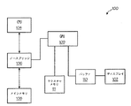
図1〜3を参照すると、本発明の一実施形態では、直線は、ディスプレイシステム100のディスプレイ102上に表示される。ディスプレイシステム100は、グラフィックおよび/またはテキスト情報をユーザまたはオペレータに表示する必要がある環境で使用されうる。一実施形態では、ディスプレイシステム100は、航空機内で使用され、ディスプレイ102は、航空機の高度のグラフィック表現などのフライト情報を表示する。例えば、まっすぐな水平線は、水平な航空機を表すことができ、一方で傾斜した線は、横傾斜の航空機を表すことができる。
1-3, in one embodiment of the invention, the straight line is displayed on the
ディスプレイシステム100は、さらに、メインメモリ108およびグラフィック処理ユニット109に結合するノースブリッジインターフェイス106などのメモリアービトレータに結合された中央処理ユニット104を備える。グラフィック処理ユニット109は、フレームバッファ110を介してディスプレイ102に結合する。
中央処理ユニット(CPU)104は、一実施形態では、航空機実施形態における高度センサなどのさまざまなサブシステムからデータを受信し、さまざまなタスクのうちとりわけ、グラフィック処理ユニットに送るデータを準備する。好適なCPU 104は、当業ではよく知られており、カリフォルニア州サンノゼのインテル社などのメーカーから市販されている。 A central processing unit (CPU) 104, in one embodiment, receives data from various subsystems, such as altitude sensors in aircraft embodiments, and prepares data to be sent to a graphics processing unit, among other tasks. Suitable CPUs 104 are well known in the art and are commercially available from manufacturers such as Intel Corporation of San Jose, California.
メインメモリ108は、CPU 104およびグラフィック処理ユニット109で必要とされ、実行されるデータおよびコンピュータプログラムを格納する。メインメモリ108は、ランダムアクセスメモリ(RAM)、読取り専用メモリ(ROM)、フラッシュメモリなど、どのような標準的な手段によっても実装されうる。さまざまなメモリコンポーネントが混合され、整合が取られ、最終設計の選択は、当業者であれば容易に行えることは当業ではよく知られている。メモリは、アイダホ州ボイシのマイクロン社などのメーカーから市販されている。
グラフィック処理ユニット109は、CPU 104から表示されるデータを受け取り、ディスプレイ102を駆動するために使用されるコマンドを生成する。グラフィック処理ユニット109は、メインメモリ108に格納されているソフトウェアルーチンを実行して、ディスプレイ102を駆動するコマンドを生成する。CPU 104およびメインメモリ108は、ノースブリッジインターフェイス106などのメモリアービトレータを介してCPU 109に結合する。ノースブリッジインターフェイス106は、CPU 104、メインメモリ108、およびGPU 109の間のインターフェイスを形成する(アドバンスグラフィックポートまたは類似のグラフィックポートを介して)。
The
さらに、本発明では、グラフィック処理ユニット109は、テクスチャメモリ111からテクスチャマップの形でデータを受信し、テクスチャマッピングを実行して、以下で詳述するように、ラインおよび文字を形成する。GPU 109は、カリフォルニア州サンタクララのNVIDIA社を含む多くの企業から市販され、製造されている。ノースブリッジインターフェイス106は、当業では知られており、カリフォルニア州サンノゼのインテル社などのメーカーから入手可能である。テクスチャメモリ111は、RAM、フラッシュメモリなどテクスチャマッピングを格納することができるメモリであればどのようなタイプのものでもよい。
Furthermore, in the present invention, the
すでに説明されているように、民生品のGPUを使用すると、ディスプレイシステムにはラインおよび文字のエイリアシングが生じる。エイリアシングは、低解像度ディスプレイではより顕著になる傾向があるが(例えば、2.54cm(1インチ)当たり120ドット以下)、本発明の教示は、任意の解像度のディスプレイに適用可能である。市販のGPUは、通常、ラインを、センタ領域のいずれかの側の域外ピクセルでは減少する輝度を持つ領域を含む1つの完全輝度センタ領域(すべてのピクセルが完全にラインによりおおわれている)として描画する。これらの域外ピクセルの輝度は、それぞれの域外ピクセルのラインの百分率範囲を反映する。例えば、幅1.5のピクセル水平線がピクセル行をセンタに描画される場合、そのラインの長さに対するそのピクセル行の内側にあるすべてのピクセルは、十分におおわれ、十分な輝度で描画される。このセンタ行の真上および真下のピクセルは、ラインによって1/4おおわれ、センタの25%で強化される。このように輝度の変化が粗いため、ブロックエッジまたはエイリアシングが生じる。ラインのエイリアシングを避けるため、本発明では、テクスチャマッピングが使用され、ラインエッジが複数の域外ピクセルにまたがって明から暗まで徐々に遷移するようにラインを描画する。 As already explained, the use of consumer GPUs results in line and character aliasing in the display system. Although aliasing tends to be more pronounced in low resolution displays (eg, 120 dots or less per inch), the teachings of the present invention are applicable to any resolution display. Commercially available GPUs usually draw a line as one full brightness center area (all pixels are completely covered by the line), including areas with reduced brightness at out-of-range pixels on either side of the center area. To do. The luminance of these out-of-range pixels reflects the percentage range of each out-of-range pixel line. For example, if a pixel horizontal line with a width of 1.5 is drawn centered on a pixel row, all pixels inside the pixel row for the length of the line are fully covered and drawn with sufficient brightness. The pixels directly above and below this center row are covered by a line and are enhanced by 25% of the center. Since the luminance change is rough, block edge or aliasing occurs. To avoid line aliasing, the present invention uses texture mapping to draw lines so that the line edges gradually transition from light to dark across multiple outlier pixels.
本発明の教示によりアンチエイリアシングされたラインを出力する例示的方法は、図2a〜2bに示されている。図2a〜2bは、本発明の教示によりアンチエイリアシングされたラインを生成する方法の一実施形態を例示する流れ図である。このプロセスは、2つの段階を伴う。第1の段階では、図2aに示されているように、システムで必要なライン幅毎にテクスチャメモリを初期化する。次に、第2段階で、図2bに示されているように利用可能なライン幅のレパートリーに基づき個々のラインを描画する。 An exemplary method for outputting anti-aliased lines in accordance with the teachings of the present invention is illustrated in FIGS. 2a-2b are a flow diagram illustrating one embodiment of a method for generating anti-aliased lines in accordance with the teachings of the present invention. This process involves two stages. In the first stage, as shown in FIG. 2a, the texture memory is initialized for each line width required by the system. Next, in the second stage, individual lines are drawn based on the repertoire of available line widths as shown in FIG. 2b.
図2aを参照すると、ステップ202で、ディスプレイに表示可能なラインの本数が選択される。例えば、一実施形態では、0.41mm(16mils)、0.48mm(19mils)、0.71mm(28mils)、および1.07mm(42mils)のライン幅が使用可能である。これらの幅は、例示する目的でのみ使用され、任意のライン幅または一連のライン幅が選択されうる。通常、太さは、表示される情報を設計する際に選択される。
Referring to FIG. 2a, at
その後、ステップ204で、ライン幅毎に、テクスチャマップのテクスチャ幅が、ライン幅から計算される。テクスチャ幅は、ライン幅よりも上の次の2のべき乗に等しい。例えば、ライン幅が0.05cm(0.02インチ)の場合、テクスチャ幅は少なくとも0.05cm(0.02インチ)である。テクスチャ幅はテクスチャマップの縦軸(s軸)である。テクスチャ長は、テクスチャ幅の2倍であり、横軸(t軸)である。したがって、横軸(t軸)は、縦軸(s軸)の2倍大きい。テクスチャマップ毎に、テクスチャメモリ内の領域に、テクスチャ幅×2×テクスチャ幅のサイズが割り当てられる(ステップ206)。
Thereafter, in
次に、ステップ208で、テクスチャマップがライン幅毎に作成される。例示的な一実施形態では、それぞれのテクスチャマップは、一連の同心半円を含み、それぞれの半円は減少する輝度を表し、輝度は半円の半径が増大するとともに減少する。輝度の減少は、対称分布曲線に従う。この分布曲線は、通常、ライン幅の1/2に相関する距離のところで半輝度点に達するように描画される。一実施形態では、輝度はガウス分布に従って減少するが、他の対称分布曲線が使用されることも可能である。図3aには、ガウス曲線302が示されている。ガウス曲線は、以下の公式により生成される。
Next, in

ガウス曲線302では、図3aからわかるように、最大輝度を表す最大値Aは、分布のセンタにあることに注意されたい。輝度は、センタ値Aのいずれかの側で減衰する。本発明では、ガウス曲線302は、ラインの所望の外観をモデル化するために使用されることができる。ラインのセンタは、ラインの最も輝度の高い部分となり、センタ部のいずれかの側のラインの輝度は、ガウス分布に従って減少する。ガウス曲線の滑らかな対称的な減少により、ラインの外観が滑らかに漸減し、エイリアシングの効果を排除できる。
Note that in the
一実施形態では、ガウス曲線302は、図3aに示されているように、0.41mm(16mil)ラインに使用される。0.41mm(16mil)ラインでは、50%の点の間にテクスチャマップ空間内に0.41mm(16mil)の分離相当分がある、つまり、それは、f(x)値が、ガウス曲線302上の点Bおよび点Cにより例示されているように最大値の半分である点である。図3bは、0.48mm(19mil)ラインに対するガウス曲線304を例示する。ガウス曲線304は、50%点の間の0.48mm(19mil)の分離相当分を持つ。これは、図3bのガウス曲線304に例示されており、ガウス曲線304上の点Dと点Eとの間に0.48mm(19mil)の分離相当分があり、点Dおよび点Eは50%点である。
In one embodiment, a
図4に、ガウス分布を使用する0.41mm(16mil)ラインに対し生成されたテクスチャマップ402を例示する。一実施形態では、テクスチャマップ402は、それぞれの半円が特定の輝度を表す一連の同心半円を含む。半円の半径が大きいほど、半円が表す輝度は低くなる。前述のように、一実施形態では、輝度は、ガウス分布に基づいて減衰する。例えば、例として示すテクスチャマップ402は、図3aに示されているガウス分布に基づく。図4に示されているように、第1の曲線404は、特定の輝度を表す。例えば、FFhexが最高輝度を表し、0hexが最低輝度を表す一実施形態では、第1の曲線404は、80hexの輝度を持つことができる。大きな半径を持つ第2の曲線406は、40hexの輝度を表すことができる。これら2つの曲線の間の点は、2つの値の間で一様に遷移する。したがって、半円の半径が増大すると、半円が表す輝度値は減少する。一実施形態では、使用されることができるそれぞれの異なるライン幅について異なるテクスチャマップがある。ステップ210で、異なるテクスチャマップがテクスチャメモリに格納される。
FIG. 4 illustrates a
一実施形態では、半円は、ライン幅の半径を持つ半円内に描画される。図4に示されているように、横軸はt軸であり、縦軸はs軸である。テクスチャマップのプロファイルは、s=1、t=0.5をセンタとする。 In one embodiment, the semicircle is drawn within a semicircle having a line width radius. As shown in FIG. 4, the horizontal axis is the t-axis, and the vertical axis is the s-axis. The profile of the texture map is centered at s = 1 and t = 0.5.
次に図2bを参照すると、いったんテクスチャマップ402が生成されると、テクスチャマップ402は、アンチエイリアシングされたラインを生成するために使用されることができる。第1に、計算されるライン幅およびラインの終点は、ステップ232で与えられる。次に、テクスチャマッピングが有効にされ、ラインサイズに対する適切なラインテクスチャが選択される(ステップ234)。また、このステップで、与えられたテクスチャに対するテクスチャ幅が受け取られる。一実施形態では、ラインは、丸められた2つの終点を使用して、丸められた一方の終点を使用して、または丸められた終点である終点を使用しないで、描画されることができる。ラインへの丸められた終点は、ラインをより均一に見せかけ、アンチエイリアシングされたエッジを持たせる傾向があるが、描画するのには幾分より複雑でもある。ステップ236で、ラインに対し2つの丸められた終点を使用するのか、単一/丸められていない終点を使用するのかの選択が行われる。
Referring now to FIG. 2b, once the
丸められていない終点が使用される場合、テクスチャマップの最下行のみがマッピングされラインを形成する。テクスチャマップの最下行は図4のボックス408として示され、s軸内で、またt軸全体にまたがって1テクセルだけ延びている(テクセルは、1ピクセルに相当するテクスチャ空間である)。図5aでは、適用されるテクスチャマップを持つ、例としてのライン502が示されている。ラインは、終点(X1,Y1)から(X2,Y2)まで描画される。ラインは、(X1,Y1)と(X2,Y2)の間のラインのセンタを縦方向に等分する矩形を形成することにより描画される。その矩形の隅の座標は、図5aで、X、Y、S、Tの形で指定され、XおよびYは表示空間内のラインの隅のデカルト座標であり、SおよびTはライン502に適用されるようなテクスチャマップのデカルト座標である。T座標は、ラインに垂直に0から1まで変化し、Sは、ラインに平行に1.0の定数に設定されることに注意されたい。このため、テクスチャマップの最後の行(S=1)はラインの全長にわたって引き延ばされる。OPENGLの用語では、これは、テクスチャエッジクランピングと呼ばれる。ラインのセンタは、完全輝度であり、センタからライン幅の半分のところにあるピクセルは半輝度である。矩形領域内のそれぞれのピクセルのSおよびT座標は、X、YとS、Tの両方における矩形内の同じ相対オフセットとなるように計算される(ステップ238)。しかし、S座標は矩形の両端で同じであるため、すべてのピクセルは同じS値を持つことになる(S値は変わらない)。その一方で、T座標はライン502の幅にそって0から1に遷移する。
If an unrounded end point is used, only the bottom line of the texture map is mapped to form a line. The bottom row of the texture map is shown as
ライン502のセンタでは、T=0.5およびS=1であるテクスチャマップのセンタがマッピングされることに注意されたい。テクスチャマップ402は、T=0.5およびS=1で全輝度である。T=0およびT=1では、テクスチャマップ402の輝度は0であり、したがって、ライン502上の相当する位置は、0輝度またはその付近である。ライン502のセンタからライン幅オフセットの半分のところにあるピクセルは、T=0.25またはT=0.75であるテクスチャマップ402の部分を持つ。T=0.25またはT=0.75のところのテクスチャマップの輝度は50%輝度を表す。つまり、テクスチャマップ402のセンタは、ライン502のセンタ501にマッピングされ、テクスチャマップ402のエンドは、輝度が0輝度に近づくか、または0輝度の場合に、ライン502の幅のエンドにマッピングされる(ステップ240)。テクスチャマップを実行するために使用される正確なプロセスは当業ではよく知られている。例えば、「Introduction to Computer Graphics(コンピュータグラフィックスへの入門),by J.D.Foley,A.van Dam,S.K.Feiner,J.F.Hughes,and R.L.Philips,Addison−Wesley,1994」でテクスチャマッピングの概要が説明されている。この文献は、参照により本明細書に組み込まれる。ラインを生成するためにオーバーサンプリングを使用するのが好ましい。オーバーサンプリングでは、複数のテクセルを使用して、それぞれのピクセルにマッピングする。一実施形態では、4×4のテクセルのアレイが、16回のオーバーサンプリングで、表示空間内のそれぞれのピクセルにマッピングされる。オーバーサンプリングの他のレベルは使用できるか、またはオーバーサンプリングは使用されることができない。
Note that at the center of
単一の丸められたエッジを持つラインも、単一テクスチャ化矩形で描画されることができる。この実施形態では、この矩形は、再び、センタラインにより等分されるが、図5bに示されているように、一方のエッジ上で延長され、丸められたエッジを囲む。その後、テクスチャ化矩形は、丸められた端のS=0から丸められていない端のS=Nまで描画される。Nは、(X1,Y1)を通るラインの垂直でS=1となるように計算される。これにより、エンドキャップ(丸められたエンド)は、S=0からS=1の場合の矩形についてテクスチャマップ全体をマッピングすることにより第1の終点の左にある小さな延長矩形内に丸められる。その後、テクスチャマップ402の最後の行(S=1)が、(X1,Y1)から(X2,Y2)までのラインの長さにまたがって繰り返される。テクスチャモードは、完全テクスチャを繰り返すのではなく、エッジテクセル(S=1およびT=0から1の場合)を「クランプ」する(または繰り返す)ように設定されなければならないことに注意されたい。テクスチャエッジクランピングでは、S=1とS=Nとの間のすべてのテクセルは、S=1テクセルにマッピングされる。T座標は、丸められていない場合について説明されているのと同じように機能する。他のエンド(X2,Y2)は、単に2つの座標を切り換えることにより丸められることができることに注意されたい(X2,Y2からX1,Y1まで描画)。
A line with a single rounded edge can also be drawn with a single textured rectangle. In this embodiment, this rectangle is again equally divided by the centerline, but extends on one edge and surrounds the rounded edge, as shown in FIG. 5b. The textured rectangle is then drawn from the rounded end S = 0 to the unrounded end S = N. N is calculated to be S = 1 perpendicular to the line passing through (X1, Y1). This causes the end cap (rounded end) to be rounded into a small extension rectangle to the left of the first endpoint by mapping the entire texture map for the rectangle with S = 0 to S = 1. Thereafter, the last row (S = 1) of the
ラインが2つの丸められたエッジを持つ場合、ライン602は、図6に示されているように2つの四辺形で構成することができる。ライン602を描画する最も単純な方法は、ラインを等分し、2つのサイズの等しい矩形(2つの四辺形など)を描画することである。しかし、例示的方法は、ライン602がライン602の長さにそった任意の1点で分割される場合に機能する。例えば、完全なラインは、上述のように単一エンドキャップで描画され、その後、第2の矩形は、第2のエンドキャップをレンダリングだけするように描画できる。ラインを等分し、2つの等しい四辺形を使用する利点は、SおよびT座標が両方の矩形について同じであり、これにより、単一の三角形メッシュで両方の矩形をレンダリングできることにある。描画されるラインの中点から始めると、テクスチャマップ402の第1行を含むテクスチャマップ402の部分は、図6のNmidというラベルが付いている中点から、1のラベルが付いているラインの点にマッピングされる。ステップ212では、点N=1からN=0まで、テクスチャマップ全体がラインのエンドの描画に使用される。テクスチャマップは減少する輝度を表す一連の同心半円であるため、ラインのエンドは、減少する輝度を持つ半円として現れる。ラインの半分が描画されると、残り半分も、ステップ214で、ラインの中点から他エンドまで描画される。
If the line has two rounded edges, the
例えば、図6に示されているラインでは、ライン602のセンタ603からライン602の半輝度点605までの距離はライン幅の半分である。ライン602の半点輝度点605は、ラインの輝度が最大輝度の半分である点である。これは、さらに減少する輝度を持つ半輝度点605を過ぎて続くライン602の全幅ではない。したがって、テクスチャマップ402が適用されると、テクスチャマップ402の真ん中にある点からテクスチャマップ402の半輝度点を表す点までが、ラインのセンタからラインの半輝度点605までマッピングされる。図6の例では、1024×768の解像度に設定されている15インチ画面上の、例として示す0.41mm(16mil)のラインについてはセンタ603から半輝度点605までのライン602の幅は約1.35ピクセルである。これは、図4のテクスチャマップのセンタから図4の50%の輝度同心半円までは、ライン602のセンタ603からライン602の半輝度点605まで(ライン602のセンタ603の両側で)にマッピングされるということを意味する。つまり、テクスチャマップのセンタから50%同心半円までの距離は、ラインスペースで決められたように1.35ピクセルだけ延びる。テクスチャマップは、同心半円を含むので、テクスチャ全体がラインにマッピングされる場合のラインの中点では、センタ603から半輝度点605までのその距離はラインのエンドの丸められた部分の先端の50%の輝度まで延びる半円の半径である。
For example, in the line shown in FIG. 6, the distance from the
図5a、5b、および6に示されているように頂点を決定する際に必要になる計算を説明するために、以下の方程式が使用できるが、計算されるラインの種類については少し変更がある。以下の方程式は、2つの丸められたエッジを持つラインの場合のものである。以下の計算では、X1=1.2、Y1=0.8、X2=1.6、Y2=0.5、TextureWidth=0.02である。 The following equations can be used to illustrate the calculations required in determining vertices as shown in FIGS. 5a, 5b, and 6, but there are slight changes to the types of lines that are calculated: . The following equation is for a line with two rounded edges. In the following calculation, X1 = 1.2, Y1 = 0.8, X2 = 1.6, Y2 = 0.5, and TextureWidth = 0.02.
ラインへの丸められた終点を描画する上記の方法は、例にすぎず、本発明で開示されているようにテクスチャマッピングを使用してラインを描画するどのような方法をも使用可能である。 The above method of drawing a rounded endpoint to a line is only an example, and any method of drawing a line using texture mapping as disclosed in the present invention can be used.
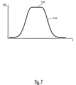
上述のように、テクスチャマッピングは、必要なときにオーバーサンプリング手法を使用していくつかのよく知られているテクスチャマッピング手段のいずれかで実行されうる。上記の方法は、使用可能なラインを形成するが、ライン幅が大きくなるにつれ、対称分布に従って輝度を下げる前にラインの輝度を高めておくことが望ましい場合が多い。図7に示されているように、平坦領域704を持つ修正された分布曲線702が例示されている。修正された分布曲線702は、ラインを生成する際に使用するテクスチャマップを生成するために使用されることができる。一例では、分布曲線702は、0.48mm(19mil)ラインのものであり、平坦領域704は幅0.08mm(3mil)である。この修正された分布曲線702は、0.08mm(3mil)の全輝度センタを持つラインを生成し、その後、輝度は、修正された分布曲線702の残りの部分に従って減衰する。この例により、0.56mm(22mils)のライン幅が得られるが、輝度と鮮鋭度は、0.56mm(22mil)プロファイルで描画されたラインよりも高い。
As mentioned above, texture mapping can be performed with any of several well-known texture mapping means using oversampling techniques when needed. The above method forms a usable line, but as the line width increases, it is often desirable to increase the line brightness before decreasing the brightness according to the symmetrical distribution. As shown in FIG. 7, a modified
一実施形態では、全輝度は全白色ラインである。全白色ラインが白色表示上に描画されると、ラインは見えなくなるであろう(もちろん、同じ色のラインが同じ色の表示画面上に描画されるときにはいつでもそうなる)。ラインを表示するには、ハローが最初に描画され、その後実際のラインが描画される。ハローは、ラインに対する対比色で描画される大きなライン幅で描画されるラインに類似の形状の領域である(例えば、白色ラインに対し黒色ハロー)。本発明では、ハローは、本発明の方法を介して描画されることもできる。それぞれのライン幅は、関連付けられたハロ幅を持つことができ、それぞれのハローは、関連付けられたテクスチャマップを持つ。ハローが描画された後、黒色の切り欠き内の白色ラインとして表示されるラインが生成されるようにできる。その後、このプロセスでは、黒色ラインを書き込んで、明るい背景内に穴を切り、その後、白色ラインを(細いライン幅で)その穴に書き込む。 In one embodiment, the total brightness is an all white line. If an all white line is drawn on a white display, the line will disappear (of course, whenever a line of the same color is drawn on the same color display screen). To display a line, the halo is drawn first, followed by the actual line. A halo is an area having a shape similar to a line drawn with a large line width drawn with a contrast color for the line (for example, a black halo for a white line). In the present invention, halos can also be drawn via the method of the present invention. Each line width can have an associated halo width, and each halo has an associated texture map. After the halo is drawn, a line can be generated that is displayed as a white line in a black cutout. The process then writes a black line, cuts a hole in the light background, and then writes a white line (with a narrow line width) into the hole.
本発明の教示に従ってアンチエイリアシングされたラインを描画する方法は、もちろん、連結ラインを描画するためにも使用されることができる。そのため、本発明の方法は、どのレベルの複雑さであっても任意の「スティック」型のフィギュアを描画するために使用できる。さらに、ラインは、英数字およびシンボルを形成するために連結されることもできる。連結ラインを使用して英数字を形成する場合の欠点は、形成された文字が、エンドキャップが次のライン領域とオーバーラップする「マッチ棒」のような外観を持つため、交差点で余分な明るさを生じることがある点である。 The method of drawing anti-aliased lines according to the teachings of the present invention can of course also be used to draw connected lines. As such, the method of the present invention can be used to draw any “stick” type figure at any level of complexity. Further, the lines can be concatenated to form alphanumeric characters and symbols. The disadvantage of using connecting lines to form alphanumeric characters is that the letters formed look like a “match bar” where the end cap overlaps with the next line area, so extra light at the intersection. This is a point that may cause a problem.
アンチエイリアシングされた文字を形成する他の方法は図8〜10に例示されている。この方法は、表示されるそれぞれの文字に対応するテクスチャマップを計算する。文字に対するテクスチャマップの形成を開始するために、図8に示されているように、文字は、一連のラインセグメントのみとしてキャラクタマップ(800)上に描画される。図8では、文字X 801は、第1のラインセグメント802および第2のラインセグメント804により表される。図8のそれぞれのテクセル(テクスチャ領域内のピクセルに相当)について、そのテクセルから文字内のそれぞれのラインセグメントまでの距離が計算されることができる。テクセルとラインセグメントとの間の最小距離は、そのテクセルに対する輝度値を求めるためにガウス分布などの分布とともに使用される。テクセルからラインペアまでの距離が等しい場合、ラインはテクセルと関連付けられることが可能である。輝度は、前のように見つけられるであろう。輝度はテクセル毎に記録される。
Another method of forming anti-aliased characters is illustrated in FIGS. This method calculates a texture map corresponding to each displayed character. To begin forming a texture map for a character, the character is drawn on the character map (800) as only a series of line segments, as shown in FIG. In FIG. 8, the
例えば、図8の点A(点(t1,s1)に対応する)は、ラインセグメント802からの距離x1およびラインセグメント804からの距離x2である。この例では、距離x1は、距離x2よりも小さい。したがって、距離x1は、そのテクセルに割り当てられる輝度値を決定するために使用される。テクセルに割り当てられる輝度値は、図9のガウス分布などの基準分布を使用することにより見つけられる。
For example, point A in FIG. 8 (corresponding to point (t 1 , s 1 )) is distance x 1 from
図9aは、輝度対ラインからの距離についての例示的なガウス輝度分布曲線902を示している。再び図8を参照すると、文字を構成するラインセグメント上に置かれるすべての点は、全輝度である。図8の与えられた例では、テクセルとラインとの間の距離はx1であった。距離x1は、図9aの輝度分布曲線902のx軸上に配置される。読んで行くと、その位置について輝度がI1であることがわかる。テクスチャマップのテクセルには、この値を割り当てられる。
FIG. 9a shows an exemplary Gaussian
例としてのキャラクタテクスチャマップ(1000)が図10に示されている。文字1002は、図1〜7で説明されているラインと同様に、点線のアウトライン1004として示されている、センタラインのいずれかの側に減少する輝度を示す全輝度センタラインを持つ。図8の点(t1,s1)は、図10上で点A’とラベル付けされている。本発明では、テクスチャマップが、表示されるそれぞれの英数字またはシンボルについて生成される。テクスチャマップは、その後、テクスチャメモリ111に格納される。テクスチャマップは、当業で知られているように、文字またはシンボルを出力するため任意の多角形領域にマッピングされることができる。
An example character texture map (1000) is shown in FIG. The
図1〜7のラインの描画とともに説明されているように、いくつかの背景に対してラインの可視性を高めるために、対比色の「ハロー」が描画され、その後、ラインがハロー内に描画される。例えば、すでに説明されているように、白色ラインを白色背景に表示するために、黒色ハローが描画され、白色ラインはその黒色ハロー内に描画されることになる。本発明では、文字とともにハロを表示するために、所定のテクセルに対するハロー値は、そのハロに対する輝度値が計算されるのと同時に計算されることができる。図9bでは、ハロ輝度に対するハロー分布曲線904が示されている。図9bの分布曲線は図9aの輝度分布曲線902よりも遠くまで広がる。つまり、輝度が非常に小さいか、または存在しないラインからの距離では、ハロー値が存在するということである。このため、文字よりも広いハローが可能であり、つまり、ハローは文字の周りを囲む。この実施形態では、所定テクセルは、輝度値とハロー値の両方を格納する。例えば、図9aでは、点x1は、I1の関連する輝度値(輝度)を持つ。図9bから、点X1は、α1の関連するハロー値(アルファ)を持つ。「OpenGLTM(登録商標)」の用語では、ハローは、テクスチャコンポーネントのアルファ値を表し、輝度値はルミナンスを表す。
As described with the line drawing in FIGS. 1-7, a contrasting “halo” is drawn to increase the visibility of the line against some background, and then the line is drawn in the halo. Is done. For example, as already described, in order to display a white line on a white background, a black halo is drawn, and the white line is drawn in the black halo. In the present invention, to display a halo with a character, the halo value for a given texel can be calculated at the same time as the luminance value for that halo is calculated. In FIG. 9b, a
文字は、所望の文字をレンダリングするように適切に位置決めされサイズ設定された単一のテクスチャ化矩形により描画される。その後、所望の文字を含むテクスチャ領域は、テクスチャマップのT、S座標を使用して選択される。これは、所望の位置決めおよびスケーリングとともに完全な文字をマッピングする。この方法で文字を描画する主な利点は、3つある。第1は、交差点が過飽和されないため画像品質が改善される(マッチ棒効果がない)。第2に、完全な文字に対しライン毎に4から6個の頂点ではなく4つの頂点しか必要ないため、頂点の処理および伝送は、かなり縮小される点である。第3に、作業の大半は、オフラインで、またはグラフィックシステムの電源が最初に投入された後1回実行されることができ、そのため、文字描画に必要な実行時計算が大幅に低減されることである。 The characters are drawn with a single textured rectangle that is properly positioned and sized to render the desired character. Thereafter, the texture region containing the desired character is selected using the T and S coordinates of the texture map. This maps the complete character with the desired positioning and scaling. There are three main advantages of drawing characters in this way. First, image quality is improved (no matchstick effect) because the intersection is not oversaturated. Second, vertex processing and transmission is considerably reduced because only four vertices are required for a complete character instead of four to six vertices per line. Third, most of the work can be performed offline or once after the graphics system is first turned on, thus greatly reducing the run-time calculations required for character drawing. It is.
通常、1つの文字集合が必要なライン幅およびハロー幅毎に描画される。ラインおよびハロ幅が合計サイズでスケーリングされることができる限り、小さな文字から大きな文字が作成されるようにできることに注意されたい。さらに、ほとんどのアプリケーションは、テクスチャを「スーパーサンプリング」し、ラインエッジのプロファイルをより正確にマッピングする。例えば、文字は、フレームバッファ内で通常サイズにマッピングされる場合と同じくらいの大きさのテクスチャメモリの4倍に表されることができる。補間法とともにスーパーサンプリングを使用してイメージを大幅に小さくする(サイズを縮小する)ことは、高い忠実度の複製を出力する技術として当業でよく知られている。このとき、オーバーサイズのマップを保存するための余分なメモリとアンチエイリアシングの効果のレベルとの間にトレードオフの関係がある。テクスチャ内にハローフィールドを含めることは、状況に応じて可能であるが、それは、本発明は、テクセル毎にアルファ(通常1バイト)のみだけでなく、自動ハローイングに使用されるアルファ/輝度(テクセル毎に通常2バイト)と連携するからである。これは、ハロイングされた文字は、2回描画されなければならない、つまり、1回目はハロー色と幅広ライン幅で、2回目は狭いライン幅で描画されなければならないということである。これで、文字定義の数および頂点書き込み回数は2倍になるが、同じ文字を幅広のラインで描画するためにハローライン幅が使用可能であり、それぞれの文字は、テクスチャメモリ内のサイズの半分しかないためメモリを節約できる。 Normally, one character set is drawn for each required line width and halo width. Note that large characters can be created from small characters as long as the line and halo width can be scaled by the total size. In addition, most applications “supersample” the texture and more accurately map the line edge profile. For example, a character can be represented in four times as much texture memory as it is mapped to the normal size in the frame buffer. Using supersampling in conjunction with interpolation to significantly reduce an image (reducing its size) is well known in the art as a technique for outputting high fidelity replicas. At this time, there is a trade-off relationship between the extra memory for storing the oversized map and the level of the anti-aliasing effect. It is possible to include a halo field in the texture depending on the situation, but this is not only the case where the present invention is not only alpha (usually 1 byte) per texel, but also alpha / brightness used for automatic haloing ( This is because it cooperates with 2 bytes for each texel. This means that a hallowed character must be drawn twice, that is, the first time it must be drawn with a halo and a wide line width, and the second time it should be drawn with a narrow line width. This doubles the number of character definitions and the number of vertex writes, but the halo line width can be used to draw the same character with a wide line, and each character is half the size in the texture memory. It can only save memory.
前記詳細な説明では、少なくとも1つの例示的実施形態が提示されたが、膨大な数の変更形態が存在することは理解されるであろう。また、1つまたは複数の例示的実施形態は、例にすぎず、本発明の範囲、適用性、または構成をいかなる形でも限定することは意図されていないことも理解されるであろう。むしろ、前記の詳細な説明は、当業者にとって、1つまたは複数の例示的実施形態を実施するための簡便なロードマップとなるであろう。請求項およびその法的等価物で規定されているように、本発明の範囲から逸脱することなく要素の機能および配置にさまざまな変更が加えられることは理解されるであろう。 While at least one exemplary embodiment has been presented in the foregoing detailed description, it will be appreciated that a vast number of variations exist. It will also be appreciated that the exemplary embodiment or exemplary embodiments are only examples, and are not intended to limit the scope, applicability, or configuration of the invention in any way. Rather, the foregoing detailed description will be a convenient roadmap for implementing one or more exemplary embodiments for those skilled in the art. It will be understood that various changes may be made in the function and arrangement of elements without departing from the scope of the invention as defined in the claims and their legal equivalents.
Claims (4)
単一の多角形領域(502、602)内に表示されるべき各ラインまたは各文字に対してテクスチャメモリ(111)に前記生成された単一のテクスチャマップを格納するステップと、
少なくともひとつのアンチエイリアシングされたエンドを含む、ラインおよび文字をディスプレイ(102)上に形成するために前記単一のテクスチャマップを前記多角形領域に適用するステップと、
を含む、グラフィック処理ユニット(109)によりアンチエイリアシングされたラインおよび文字を生成する方法。Generating a single texture map (402) comprising a series of concentric semicircles (404) based on a symmetric distribution (302), each concentric semicircle having a brightness that decreases as the radius of the concentric semicircle increases; Represents
Storing the generated single texture map in a texture memory (111) for each line or character to be displayed in a single polygonal area (502, 602);
Applying the single texture map to the polygonal region to form lines and characters on the display (102) , including at least one anti-aliased end ;
Generating lines and characters anti-aliased by the graphics processing unit (109).
文字(801)を形成する各ラインセグメント(802)と前記テクセルの間の最小距離を決定するステップと、
前記最小距離を使用して、対称分布(302)に基づき輝度値を決定するステップと、
前記テクセルと前記輝度値(I1)とを関連付けて、前記テクスチャマップを形成するステップとを含む、請求項1に記載の方法。The step of generating a texture map based on the symmetric distribution further includes for texels in the texture map:
Determining a minimum distance between each line segment (802) forming the character (801) and the texel;
Using the minimum distance to determine a luminance value based on a symmetric distribution (302);
The method according to claim 1, comprising associating the texel with the luminance value (I 1 ) to form the texture map.
前記テクスチャメモリ(111)に結合され、少なくともひとつのアンチエイリアシングされたエンドを含む、単一のテクスチャマップ(402)を単一の多角形領域(502、602)に適用して、ひとつのアンチエイリアスされたラインおよび文字を形成するように動作可能なグラフィックプロセッサユニット(109)と、
を備えるアンチエイリアシングされたラインおよび文字を形成するディスプレイシステム(100)。A texture memory for storing at least one texture map (402) generated using a symmetrical distribution (302) comprising a series of concentric semicircles (404, 405) for each line or character displayed. 111), and each said concentric semicircle represents a luminance that decreases as the radius of the concentric semicircle increases,
Coupled to said texture memory (111), includes an end that is at least one anti-aliasing, by applying a single texture map (402) into a single polygonal region (502, 602), is one of the anti-aliasing A graphics processor unit (109) operable to form a line and character;
A display system (100) for forming anti-aliased lines and characters comprising:
Applications Claiming Priority (3)
| Application Number | Priority Date | Filing Date | Title |
|---|---|---|---|
| US47233503P | 2003-05-20 | 2003-05-20 | |
| US60/472,335 | 2003-05-20 | ||
| PCT/US2004/016241 WO2004104929A2 (en) | 2003-05-20 | 2004-05-20 | Texture based method and system for the anti-aliasing of lines and characters |
Publications (3)
| Publication Number | Publication Date |
|---|---|
| JP2007505421A JP2007505421A (en) | 2007-03-08 |
| JP2007505421A5 JP2007505421A5 (en) | 2007-06-14 |
| JP4717000B2 true JP4717000B2 (en) | 2011-07-06 |
Family
ID=33476941
Family Applications (1)
| Application Number | Title | Priority Date | Filing Date |
|---|---|---|---|
| JP2006533344A Expired - Fee Related JP4717000B2 (en) | 2003-05-20 | 2004-05-20 | Texture-based method and system for line and character anti-aliasing |
Country Status (3)
| Country | Link |
|---|---|
| US (2) | US7456851B2 (en) |
| JP (1) | JP4717000B2 (en) |
| WO (1) | WO2004104929A2 (en) |
Families Citing this family (19)
| Publication number | Priority date | Publication date | Assignee | Title |
|---|---|---|---|---|
| US7050067B2 (en) * | 2003-01-13 | 2006-05-23 | Microsoft Corporation | Hardware accelerated anti-aliased primitives using alpha gradients |
| US7502024B2 (en) * | 2003-09-25 | 2009-03-10 | Honeywell International Inc. | Texture based circular arc generation |
| WO2007037042A1 (en) * | 2005-09-27 | 2007-04-05 | Sharp Kabushiki Kaisha | Liquid crystal display device, instrument panel, automotive vehicle, and liquid crystal display method |
| US7412554B2 (en) * | 2006-06-15 | 2008-08-12 | Nvidia Corporation | Bus interface controller for cost-effective high performance graphics system with two or more graphics processing units |
| US7500041B2 (en) * | 2006-06-15 | 2009-03-03 | Nvidia Corporation | Graphics processing unit for cost effective high performance graphics system with two or more graphics processing units |
| US7562174B2 (en) * | 2006-06-15 | 2009-07-14 | Nvidia Corporation | Motherboard having hard-wired private bus between graphics cards |
| US7890747B2 (en) * | 2006-07-06 | 2011-02-15 | Accenture Global Services Limited | Display of decrypted data by a graphics processing unit |
| US7724260B2 (en) | 2006-08-25 | 2010-05-25 | Honeywell International Inc. | Method and system for image monitoring |
| GB2445982A (en) * | 2007-01-24 | 2008-07-30 | Sharp Kk | Image data processing method and apparatus for a multiview display device |
| US20090091576A1 (en) * | 2007-10-09 | 2009-04-09 | Jayanta Kumar Maitra | Interface platform |
| US9438844B2 (en) * | 2008-04-08 | 2016-09-06 | Imagine Communications Corp. | Video multiviewer system using direct memory access (DMA) registers and block RAM |
| US9716854B2 (en) * | 2008-04-09 | 2017-07-25 | Imagine Communications Corp. | Video multiviewer system with distributed scaling and related methods |
| US9172900B2 (en) * | 2008-04-09 | 2015-10-27 | Imagine Communications Corp. | Video multiviewer system with switcher and distributed scaling and related methods |
| US8587639B2 (en) * | 2008-12-11 | 2013-11-19 | Alcatel Lucent | Method of improved three dimensional display technique |
| DE102009042235A1 (en) * | 2009-09-18 | 2011-04-07 | Diehl Aerospace Gmbh | Method for displaying a plurality of at least partially overlapping objects |
| US9098938B2 (en) * | 2011-11-10 | 2015-08-04 | The Directv Group, Inc. | System and method for drawing anti-aliased lines in any direction |
| MX2015011424A (en) * | 2013-03-06 | 2016-06-06 | Arthur J Zito Jr | Multi-media presentation system. |
| US10395408B1 (en) * | 2016-10-14 | 2019-08-27 | Gopro, Inc. | Systems and methods for rendering vector shapes |
| USD875117S1 (en) * | 2018-05-31 | 2020-02-11 | Nutanix, Inc. | Display panel or portion thereof with transitional graphical user interface |
Citations (2)
| Publication number | Priority date | Publication date | Assignee | Title |
|---|---|---|---|---|
| US5596692A (en) * | 1990-06-08 | 1997-01-21 | Accom, Incorporated | Computer graphics |
| JP2001175884A (en) * | 1999-12-17 | 2001-06-29 | Namco Ltd | Image generation system and information storage medium |
Family Cites Families (26)
| Publication number | Priority date | Publication date | Assignee | Title |
|---|---|---|---|---|
| US5381519A (en) | 1987-12-04 | 1995-01-10 | Evans & Sutherland Computer Corp. | System for line interpolation for computer graphics displays |
| US5339092A (en) * | 1989-11-06 | 1994-08-16 | Honeywell Inc | Beam former for matrix display |
| US5224208A (en) | 1990-03-16 | 1993-06-29 | Hewlett-Packard Company | Gradient calculation for texture mapping |
| JPH04100180A (en) * | 1990-08-20 | 1992-04-02 | Japan Aviation Electron Ind Ltd | Vector generator |
| US5264838A (en) | 1991-08-29 | 1993-11-23 | Honeywell Inc. | Apparatus for generating an anti-aliased display image halo |
| DE69314231T2 (en) | 1992-04-24 | 1998-03-05 | Sony Uk Ltd | Exposure effects for a digital video effects system |
| EP0723689B1 (en) | 1993-10-15 | 1998-02-04 | EVANS & SUTHERLAND COMPUTER CORPORATION | Direct rendering of textured height fields |
| US5592597A (en) * | 1994-02-14 | 1997-01-07 | Parametric Technology Corporation | Real-time image generation system for simulating physical paint, drawing media, and feature modeling with 3-D graphics |
| US5585863A (en) * | 1995-04-07 | 1996-12-17 | Eastman Kodak Company | Memory organizing and addressing method for digital video images |
| US6348929B1 (en) * | 1998-01-16 | 2002-02-19 | Intel Corporation | Scaling algorithm and architecture for integer scaling in video |
| JP4311877B2 (en) * | 1998-03-05 | 2009-08-12 | マイクロソフト コーポレーション | Anti-aliasing of subsampled texture edges |
| US6782129B1 (en) * | 1998-09-23 | 2004-08-24 | Xerox Corporation | Image segmentation apparatus and method |
| US6188385B1 (en) | 1998-10-07 | 2001-02-13 | Microsoft Corporation | Method and apparatus for displaying images such as text |
| US6278434B1 (en) | 1998-10-07 | 2001-08-21 | Microsoft Corporation | Non-square scaling of image data to be mapped to pixel sub-components |
| US6606089B1 (en) | 1999-06-08 | 2003-08-12 | Sulzer Market And Technology Ag | Method for visualizing a spatially resolved data set |
| US6700672B1 (en) * | 1999-07-30 | 2004-03-02 | Mitsubishi Electric Research Labs, Inc. | Anti-aliasing with line samples |
| US6282327B1 (en) | 1999-07-30 | 2001-08-28 | Microsoft Corporation | Maintaining advance widths of existing characters that have been resolution enhanced |
| US7113231B2 (en) * | 2000-02-14 | 2006-09-26 | 3M Innovative Properties Company | Dot-sequential color display system |
| US6518968B1 (en) | 2000-05-17 | 2003-02-11 | Hewlett-Packard Company | Method and apparatus for performing H-space bump mapping suitable for implementation with H-space lighting in a graphics pipeline of a computer graphics display system |
| JP3770459B2 (en) * | 2000-05-23 | 2006-04-26 | シャープ株式会社 | Image display device, image display method, and recording medium |
| JP3552105B2 (en) * | 2000-05-26 | 2004-08-11 | シャープ株式会社 | Graphic display device, character display device, display method, recording medium, and program |
| KR100395766B1 (en) | 2001-02-12 | 2003-08-25 | 삼성전자주식회사 | Ferroelectric memory device and method of forming the same |
| US7030884B2 (en) * | 2003-02-13 | 2006-04-18 | Hewlett-Packard Development Company, L.P. | System and method for resampling texture maps |
| US7259764B2 (en) * | 2003-05-14 | 2007-08-21 | Pixar | Defrobulated angles for character joint representation |
| US6954211B2 (en) | 2003-06-30 | 2005-10-11 | Microsoft Corporation | Hardware-accelerated anti-aliased graphics |
| US7148901B2 (en) * | 2004-05-19 | 2006-12-12 | Hewlett-Packard Development Company, L.P. | Method and device for rendering an image for a staggered color graphics display |
-
2004
- 2004-05-18 US US10/847,710 patent/US7456851B2/en not_active Expired - Fee Related
- 2004-05-20 JP JP2006533344A patent/JP4717000B2/en not_active Expired - Fee Related
- 2004-05-20 US US10/851,972 patent/US7176933B2/en not_active Expired - Lifetime
- 2004-05-20 WO PCT/US2004/016241 patent/WO2004104929A2/en active Application Filing
Patent Citations (2)
| Publication number | Priority date | Publication date | Assignee | Title |
|---|---|---|---|---|
| US5596692A (en) * | 1990-06-08 | 1997-01-21 | Accom, Incorporated | Computer graphics |
| JP2001175884A (en) * | 1999-12-17 | 2001-06-29 | Namco Ltd | Image generation system and information storage medium |
Also Published As
| Publication number | Publication date |
|---|---|
| US20040233230A1 (en) | 2004-11-25 |
| US20040233210A1 (en) | 2004-11-25 |
| US7176933B2 (en) | 2007-02-13 |
| WO2004104929A3 (en) | 2005-03-03 |
| JP2007505421A (en) | 2007-03-08 |
| WO2004104929A2 (en) | 2004-12-02 |
| US7456851B2 (en) | 2008-11-25 |
Similar Documents
| Publication | Publication Date | Title |
|---|---|---|
| JP4717000B2 (en) | Texture-based method and system for line and character anti-aliasing | |
| KR101916341B1 (en) | Gradient adjustment for texture mapping for multiple render targets with resolution that varies by screen location | |
| JP5232358B2 (en) | Rendering outline fonts | |
| US6788301B2 (en) | Active pixel determination for line generation in regionalized rasterizer displays | |
| EP2230642B1 (en) | Graphic drawing device and graphic drawing method | |
| US6897879B2 (en) | Hardware-enhanced graphics acceleration of pixel sub-component-oriented images | |
| KR20180060198A (en) | Graphic processing apparatus and method for processing texture in graphics pipeline | |
| US7002597B2 (en) | Dynamic selection of anti-aliasing procedures | |
| US6947054B2 (en) | Anisotropic filtering | |
| US10332290B2 (en) | Fast, coverage-optimized, resolution-independent and anti-aliased graphics processing | |
| US20140327689A1 (en) | Technique for real-time rendering of temporally interpolated two-dimensional contour lines on a graphics processing unit | |
| US6731300B2 (en) | Efficient anti-aliased dot rasterization | |
| US6567098B1 (en) | Method and apparatus in a data processing system for full scene anti-aliasing | |
| US6975317B2 (en) | Method for reduction of possible renderable graphics primitive shapes for rasterization | |
| US8098264B2 (en) | Method and apparatus for rendering computer graphics primitive | |
| US7006107B2 (en) | Anisotropic anti-aliasing | |
| US6867778B2 (en) | End point value correction when traversing an edge using a quantized slope value | |
| KR20180037839A (en) | Graphics processing apparatus and method for executing instruction | |
| US6992670B2 (en) | Active region determination for line generation in regionalized rasterizer displays | |
| US6529196B1 (en) | Efficient stroking of vectors with arbitrary endpoints | |
| KR100705188B1 (en) | A character font display method | |
| US20040174364A1 (en) | Rendering patterned lines in a graphics system | |
| US6831645B2 (en) | System and method for performing font operations when background color is transparent | |
| US6847368B2 (en) | Graphics system with a buddy / quad mode for faster writes | |
| US20030206167A1 (en) | Auxiliary active region determination for line width generation in regionalized rasterizer displays |
Legal Events
| Date | Code | Title | Description |
|---|---|---|---|
| A521 | Written amendment |
Free format text: JAPANESE INTERMEDIATE CODE: A523 Effective date: 20070424 |
|
| A621 | Written request for application examination |
Free format text: JAPANESE INTERMEDIATE CODE: A621 Effective date: 20070424 |
|
| A131 | Notification of reasons for refusal |
Free format text: JAPANESE INTERMEDIATE CODE: A131 Effective date: 20091217 |
|
| A601 | Written request for extension of time |
Free format text: JAPANESE INTERMEDIATE CODE: A601 Effective date: 20100317 |
|
| A602 | Written permission of extension of time |
Free format text: JAPANESE INTERMEDIATE CODE: A602 Effective date: 20100325 |
|
| A521 | Written amendment |
Free format text: JAPANESE INTERMEDIATE CODE: A523 Effective date: 20100617 |
|
| A131 | Notification of reasons for refusal |
Free format text: JAPANESE INTERMEDIATE CODE: A131 Effective date: 20100713 |
|
| A521 | Written amendment |
Free format text: JAPANESE INTERMEDIATE CODE: A523 Effective date: 20101013 |
|
| A131 | Notification of reasons for refusal |
Free format text: JAPANESE INTERMEDIATE CODE: A131 Effective date: 20101110 |
|
| A01 | Written decision to grant a patent or to grant a registration (utility model) |
Free format text: JAPANESE INTERMEDIATE CODE: A01 Effective date: 20110302 |
|
| A61 | First payment of annual fees (during grant procedure) |
Free format text: JAPANESE INTERMEDIATE CODE: A61 Effective date: 20110329 |
|
| R150 | Certificate of patent or registration of utility model |
Free format text: JAPANESE INTERMEDIATE CODE: R150 |
|
| FPAY | Renewal fee payment (event date is renewal date of database) |
Free format text: PAYMENT UNTIL: 20140408 Year of fee payment: 3 |
|
| R250 | Receipt of annual fees |
Free format text: JAPANESE INTERMEDIATE CODE: R250 |
|
| R250 | Receipt of annual fees |
Free format text: JAPANESE INTERMEDIATE CODE: R250 |
|
| R250 | Receipt of annual fees |
Free format text: JAPANESE INTERMEDIATE CODE: R250 |
|
| R250 | Receipt of annual fees |
Free format text: JAPANESE INTERMEDIATE CODE: R250 |
|
| LAPS | Cancellation because of no payment of annual fees |