JP4716409B2 - Blood purification equipment - Google Patents
Blood purification equipment Download PDFInfo
- Publication number
- JP4716409B2 JP4716409B2 JP2005091983A JP2005091983A JP4716409B2 JP 4716409 B2 JP4716409 B2 JP 4716409B2 JP 2005091983 A JP2005091983 A JP 2005091983A JP 2005091983 A JP2005091983 A JP 2005091983A JP 4716409 B2 JP4716409 B2 JP 4716409B2
- Authority
- JP
- Japan
- Prior art keywords
- blood
- blood circuit
- venous
- arterial
- valve
- Prior art date
- Legal status (The legal status is an assumption and is not a legal conclusion. Google has not performed a legal analysis and makes no representation as to the accuracy of the status listed.)
- Expired - Fee Related
Links
Images
Classifications
-
- A—HUMAN NECESSITIES
- A61—MEDICAL OR VETERINARY SCIENCE; HYGIENE
- A61M—DEVICES FOR INTRODUCING MEDIA INTO, OR ONTO, THE BODY; DEVICES FOR TRANSDUCING BODY MEDIA OR FOR TAKING MEDIA FROM THE BODY; DEVICES FOR PRODUCING OR ENDING SLEEP OR STUPOR
- A61M1/00—Suction or pumping devices for medical purposes; Devices for carrying-off, for treatment of, or for carrying-over, body-liquids; Drainage systems
- A61M1/36—Other treatment of blood in a by-pass of the natural circulatory system, e.g. temperature adaptation, irradiation ; Extra-corporeal blood circuits
- A61M1/3621—Extra-corporeal blood circuits
- A61M1/3643—Priming, rinsing before or after use
- A61M1/3644—Mode of operation
-
- B—PERFORMING OPERATIONS; TRANSPORTING
- B01—PHYSICAL OR CHEMICAL PROCESSES OR APPARATUS IN GENERAL
- B01D—SEPARATION
- B01D61/00—Processes of separation using semi-permeable membranes, e.g. dialysis, osmosis or ultrafiltration; Apparatus, accessories or auxiliary operations specially adapted therefor
- B01D61/24—Dialysis ; Membrane extraction
- B01D61/28—Apparatus therefor
Landscapes
- Health & Medical Sciences (AREA)
- Vascular Medicine (AREA)
- Heart & Thoracic Surgery (AREA)
- Engineering & Computer Science (AREA)
- Life Sciences & Earth Sciences (AREA)
- General Health & Medical Sciences (AREA)
- Cardiology (AREA)
- Veterinary Medicine (AREA)
- Public Health (AREA)
- Anesthesiology (AREA)
- Biomedical Technology (AREA)
- Hematology (AREA)
- Animal Behavior & Ethology (AREA)
- Urology & Nephrology (AREA)
- Chemical Kinetics & Catalysis (AREA)
- Water Supply & Treatment (AREA)
- Chemical & Material Sciences (AREA)
- External Artificial Organs (AREA)
Description
本発明は、ダイアライザを使用した透析治療など、患者の血液を体外循環させつつ浄化するための血液浄化装置に関するものである。 The present invention, such as dialysis treatment using dialyzer, in which about the blood purification equipment for purifying, while the patient's blood is extracorporeally circulated.
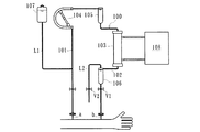
血液浄化装置としての透析装置は、図3に示すように、動脈側穿刺針aが取り付けられた動脈側血液回路101及び静脈側穿刺針bが取り付けられた静脈側血液回路102から成る血液回路100と、動脈側血液回路101及び静脈側血液回路102の間に介装されて血液回路100を流れる血液を浄化するダイアライザ103と、動脈側血液回路101に配設された血液ポンプ104と、動脈側血液回路101及び静脈側血液回路102にそれぞれ配設された動脈側ドリップチャンバ105及び静脈側ドリップチャンバ106と、静脈側ドリップチャンバ106の空気層側から延設されたオーバーフローラインL2と、ダイアライザ103に透析液を供給し得る透析装置本体108とから主に構成されている。
As shown in FIG. 3, a dialysis apparatus as a blood purification apparatus includes a
また、動脈側血液回路101における動脈側穿刺針aと血液ポンプ104との間には、生食ラインL1を介してプライミング液(生理食塩水)を収容した生食バッグ107が接続されており、透析治療前のプライミング及び透析治療中の補液等を行い得るようになっている。例えば、洗浄・プライミング時においては、動脈側穿刺針a及び静脈側穿刺針bが取り付けられる前の動脈側血液回路101先端と静脈側血液回路102先端とを接続した後、血液ポンプ104を駆動することにより、オーバーフローラインL2からプライミング液を排出させつつ血液回路100全体にプライミング液を満たしておく。
Further, a
そして、透析治療開始時には、動脈側血液回路101先端及び静脈側血液回路102先端に動脈側穿刺針a及び静脈側穿刺針bを取り付け、それぞれを患者に穿刺した後、透析装置本体108からダイアライザ103に透析液を供給しつつ血液ポンプ104を駆動することにより、患者の血液は、動脈側穿刺針aを介して血液回路100に導入され、ダイアライザ103を通って浄化及び除水された後、静脈側穿刺針bを介して患者の体内に戻ることとなる。
At the start of dialysis treatment, the arterial puncture needle a and the venous puncture needle b are attached to the distal end of the
然るに、透析治療開始時において、予め血液回路100に満たされた多量のプライミング液が静脈側穿刺針bを介して患者の体内に入ることを抑制すべく、従来、電磁弁V2を開状態及び電磁弁V1を閉状態としておき、静脈側穿刺針bの近傍がプライミング液から血液に置換されるのを目視で確認することにより、電磁弁V1を開状態及び電磁弁V2を閉状態とする。
However, at the start of dialysis treatment, the electromagnetic valve V2 has been conventionally opened and electromagnetically prevented so that a large amount of priming solution previously filled in the
上記の如き電磁弁V1及びV2の切り替え操作により、静脈側穿刺針b近傍において血液に置換される前のプライミング液は、オーバーフローラインL2から排出されるとともに、置換された血液は、静脈側穿刺針bを介して患者の体内に戻るようになっている。尚、上記の如きオーバーフローラインL2からプライミング液を排出し、血液と置換する従来技術は、例えば特許文献1にて開示されている。
しかしながら、上記従来の血液浄化装置においては、静脈側穿刺針bの近傍がプライミング液から血液に置換されるのを目視で確認して、電磁弁V1及び電磁弁V2を手動操作で切り替えるものであったため、治療開始時には、医師等の医療従事者が静脈側穿刺針b近傍を注意深く監視する必要があり、作業性が悪いものとなっていた。また、電磁弁V1及びV2の切り替えタイミングが早すぎると、患者の体内に多量のプライミング液が入ってしまう一方、切り替えタイミングが遅すぎると、体外循環した患者の血液がオーバーフローラインL2から排出されてしまうという不具合がある。 However, in the above conventional blood purification apparatus, it is visually confirmed that the vicinity of the venous puncture needle b is replaced with blood from the priming solution, and the electromagnetic valve V1 and the electromagnetic valve V2 are switched manually. Therefore, at the start of treatment, a medical worker such as a doctor needs to carefully monitor the vicinity of the venous puncture needle b, and workability is poor. Further, if the switching timing of the solenoid valves V1 and V2 is too early, a large amount of priming liquid enters the patient's body, while if the switching timing is too late, the patient's blood circulated extracorporeally is discharged from the overflow line L2. There is a problem that it ends up.
本発明は、このような事情に鑑みてなされたもので、血液浄化治療開始時において、作業性を良好とすることができるとともに、患者の体内に多量のプライミング液が入ってしまうのを回避し、且つ、体外循環した血液を確実に患者に戻すことができる血液浄化装置を提供することにある。 The present invention has been made in view of such circumstances, and can improve workability at the start of blood purification treatment and avoid a large amount of priming solution from entering the patient's body. and to provide a blood purification equipment that can be returned to the patient reliably and extracorporeal circulation blood.
請求項1記載の発明は、動脈側血液回路及び静脈側血液回路から成るとともに、予めプライミング液で満たされて、当該動脈側血液回路の先端から静脈側血液回路の先端まで患者の血液を体外循環させ得る血液回路と、該血液回路の動脈側血液回路及び静脈側血液回路の間に介装されて当該血液回路を流れる血液を浄化する血液浄化手段と、前記静脈側血液回路先端近傍を開閉可能として設けられ、当該静脈側血液回路先端から患者に流れるプライミング液及び血液を遮断又は許容する第1弁と、前記血液回路における第1弁より上流側から延設され、当該血液回路を流れるプライミング液を排出し得る排出ラインと、該排出ラインを開閉可能として設けられ、当該排出ラインを流れるプライミング液及び血液の流れを遮断又は許容する第2弁とを具備した血液浄化装置であって、前記静脈側血液回路の先端近傍であって前記第1弁より上流側が、プライミング液から血液に置換されたことを検知する検知手段を有し、該検知手段による置換の検知がなされることにより、閉状態の前記第1弁を開状態、及び開状態の前記第2弁を閉状態に自動的に切り替えるよう構成され、前記動脈側血液回路及び静脈側血液回路には、プライミング液及び血液の除泡を図るための動脈側ドリップチャンバ及び静脈側ドリップチャンバがそれぞれ設けられるとともに、前記排出ラインは当該静脈側ドリップチャンバの空気層側から延びるオーバーフローラインから成るものとされ、且つ、前記検知手段は、前記動脈側ドリップチャンバ内の液圧と静脈側ドリップチャンバ内の液圧との差圧に基づき、前記静脈側血液回路の先端近傍であって前記第1弁より上流側におけるプライミング液から血液への置換を検知することを特徴とする。
The invention according to
請求項2記載の発明は、請求項1記載の血液浄化装置において、患者の血液の体外循環開始からの経過時間を計測するタイマを有するとともに、該タイマによる計測時間に基づき、前記静脈側血液回路の先端近傍であって前記第1弁より上流側におけるプライミング液から血液への置換を検知することを特徴とする。 According to a second aspect of the invention, the blood purification apparatus according to claim 1 Symbol placement, and has a timer for measuring the elapsed time from the extracorporeal circulation initiation of the patient's blood, on the basis of the time measured by the timer, the venous blood It is characterized in that substitution of priming fluid with blood in the vicinity of the tip of the circuit and upstream of the first valve is detected.
請求項1の発明によれば、検知手段による置換の検知がなされることにより、閉状態の前記第1弁を開状態、及び開状態の前記第2弁を閉状態に自動的に切り替えるように構成されているので、血液浄化治療開始時において、作業性を良好とすることができるとともに、患者の体内に多量のプライミング液が入ってしまうのを回避し、且つ、体外循環した血液を確実に患者に戻すことができる。 According to the first aspect of the present invention, the detection means detects the replacement so that the first valve in the closed state is automatically switched to the open state and the second valve in the open state is automatically switched to the closed state. Because it is configured, it is possible to improve workability at the start of blood purification treatment, avoid a large amount of priming liquid from entering the patient's body, and ensure that extracorporeally circulated blood Can be returned to the patient.
また、排出ラインは静脈側ドリップチャンバの空気層側から延びるオーバーフローラインから成るので、プライミング時などに必要とされたオーバーフローラインを血液浄化治療時にも使用することができ、既存の血液浄化装置における構成要素を流用することができるので、製造コストを抑制することができる。 In addition , since the drain line is composed of an overflow line extending from the air layer side of the venous drip chamber, the overflow line required during priming can also be used during blood purification treatment. Since the element can be diverted, the manufacturing cost can be suppressed.
更に、動脈側ドリップチャンバ内の液圧と静脈側ドリップチャンバ内の液圧との差圧に基づき、静脈側血液回路の先端近傍におけるプライミング液から血液への置換を検知するので、既存の血液浄化装置における構成要素を流用してプライミング液から血液に置換されたことを検知でき、製造コストを抑制することができる。 Furthermore , since the replacement of priming fluid with blood in the vicinity of the tip of the venous blood circuit is detected based on the differential pressure between the fluid pressure in the arterial drip chamber and the fluid pressure in the venous drip chamber, the existing blood purification It is possible to detect that the priming liquid has been replaced with blood by diverting components in the apparatus, and manufacturing costs can be reduced.
請求項2の発明によれば、患者の血液の体外循環開始からの経過時間を計測するタイマを有するとともに、該タイマによる計測時間に基づき、静脈側血液回路の先端近傍におけるプライミング液から血液への置換を検知するので、簡単な構成にてプライミング液から血液に置換されたことを検知でき、製造コストを抑制することができる。
According to the invention of
以下、本発明の実施形態について図面を参照しながら具体的に説明する。
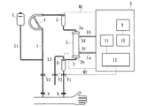
本実施形態に係る血液浄化装置は、透析治療を行うための透析装置から成り、図1に示すように、動脈側血液回路1及び静脈側血液回路2から成る血液回路と、動脈側血液回路1及び静脈側血液回路2の間に介装されて血液回路を流れる血液を浄化するダイアライザ3(血液浄化手段)と、血液ポンプ4と、動脈側血液回路1及び静脈側血液回路2にそれぞれ配設された動脈側ドリップチャンバ5及び静脈側ドリップチャンバ6と、静脈側ドリップチャンバ6の空気層側から延設されたオーバーフローラインL2(排出ライン)と、ダイアライザ3に透析液を供給し得る透析装置本体8とから主に構成されている。
Hereinafter, embodiments of the present invention will be specifically described with reference to the drawings.
The blood purification apparatus according to this embodiment includes a dialysis apparatus for performing dialysis treatment. As shown in FIG. 1, a blood circuit including an
動脈側血液回路1には、その先端に動脈側穿刺針aが接続されるとともに、途中にしごき型の血液ポンプ4及び除泡のための動脈側ドリップチャンバ5が配設されている一方、静脈側血液回路2には、その先端に静脈側穿刺針bが接続されるとともに、途中に静脈側ドリップチャンバ6が接続されている。そして、動脈側穿刺針a及び静脈側穿刺針bを患者に穿刺した状態で、血液ポンプ4を駆動させると、患者の血液は、動脈側血液回路1を通ってダイアライザ3に至った後、該ダイアライザ3によって血液浄化が施され、静脈側ドリップチャンバ6で除泡がなされつつ静脈側血液回路2を通って患者の体内に戻る。即ち、患者の血液を動脈側血液回路1の先端から静脈側血液回路2の先端まで体外循環させつつダイアライザ3にて浄化するのである。
The
ダイアライザ3は、その筐体部に、血液導入ポート3a、血液導出ポート3b、透析液導入ポート3c及び透析液導出ポート3dが形成されており、このうち血液導入ポート3aには動脈側血液回路1が、血液導出ポート3bには静脈側血液回路2がそれぞれ接続されている。また、透析液導入ポート3c及び透析液導出ポート3dは、透析装置本体8から延設された透析液導入ラインLa及び透析液排出ラインLbとそれぞれ接続されている。
The
ダイアライザ3内には、複数の中空糸が収容されており、該中空糸内部が血液の流路とされるとともに、中空糸外周面と筐体部の内周面との間が透析液の流路とされている。中空糸には、その外周面と内周面とを貫通した微少な孔(ポア)が多数形成されて中空糸膜を形成しており、該膜を介して血液中の不純物等が透析液内に透過し得るよう構成されている。
A plurality of hollow fibers are accommodated in the
一方、透析装置本体8には、ダイアライザ3中を流れる患者の血液から水分を除去するための除水ポンプ(不図示)が配設されている。更に、透析液導入ラインLaの一端がダイアライザ3(透析液導入ポート3c)に接続されるとともに、他端が所定濃度の透析液を調製する透析液供給装置(不図示)に接続されている。また、透析液排出ラインLbの一端は、ダイアライザ3(透析液導出ポート3d)に接続されるとともに、他端が図示しない廃液手段と接続されており、透析液供給装置から供給された透析液が透析液導入ラインLaを通ってダイアライザ3に至った後、透析液排出ラインLbを通って廃液手段に送られるようになっている。
On the other hand, the
動脈側ドリップチャンバ5及び静脈側ドリップチャンバ6からは、モニタチューブM1及びM2がそれぞれ延設されており、これらの先端が透析装置本体8に接続されている。また、透析装置本体8は、圧力センサ9を具備しており、モニタチューブM1及びM2により、動脈側ドリップチャンバ5内の液圧(ダイアライザ入口圧)及び静脈側ドリップチャンバ6内の液圧(静脈圧)をそれぞれ計測し得るようになっている。
Monitor tubes M1 and M2 are extended from the arterial drip chamber 5 and the venous drip chamber 6, respectively, and their tips are connected to the
更に、動脈側血液回路1における動脈側穿刺針a近傍(生食ラインL1の合流点と動脈側穿刺針aとの間)には、第3電磁弁V3が配設されるとともに、静脈側血液回路2における静脈側穿刺針b近傍(静脈側血液回路2の先端近傍であって静脈側ドリップチャンバ6と静脈側穿刺針bとの間)には、静脈側穿刺針b近傍を開閉可能として設けられ、静脈側穿刺針bから患者に流れるプライミング液及び血液を遮断又は許容し得る第1電磁弁V1が配設されている。
Further, in the vicinity of the arterial puncture needle a in the arterial blood circuit 1 (between the confluence of the saline line L1 and the arterial puncture needle a), a third electromagnetic valve V3 is disposed and the venous blood circuit is provided. 2 near the vein side puncture needle b (near the tip of the vein
また更に、動脈側血液回路1における動脈側穿刺針aと血液ポンプ4との間からは、生食ラインL1が延設され、その先端にプライミング液(生理食塩水)を収容した生食バッグ7が接続されているとともに、静脈側ドリップチャンバ6の空気層(上部)側からは、オーバーフローラインL2が延設されている。オーバーフローラインL2の途中には、当該オーバーフローラインL2を開閉可能として設けられ、プライミング液及び血液の流れを遮断又は許容するための第2電磁弁V2が配設されている。
Further, a saline feed line L1 extends from between the artery side puncture needle a and the blood pump 4 in the artery
然るに、透析治療前の洗浄・プライミング時においては、動脈側穿刺針a及び静脈側穿刺針bが取り付けられる前の動脈側血液回路1の先端と静脈側血液回路2の先端とを接続し、第1電磁弁V1〜第3電磁弁V3を開状態とした後、血液ポンプ4を駆動することにより、生食バッグ7内のプライミング液(生理食塩水)を血液回路内に導入するとともに、静脈側ドリップチャンバ6をオーバーフローした分だけオーバーフローラインL2から排出させる。これにより、血液回路全体にプライミング液が満たされることとなる。尚、プライミング終了時には、電磁弁V1及びV3を閉状態とするとともに、生食ラインL1を鉗子等によって閉塞しておく。
However, at the time of washing and priming before dialysis treatment, the tip of the
そして、透析治療開始時には、動脈側血液回路1の先端及び静脈側血液回路2の先端に動脈側穿刺針a及び静脈側穿刺針bを取り付け、それぞれを患者に穿刺した後、透析装置本体8からダイアライザ3に透析液を供給しつつ血液ポンプ4を駆動することにより、患者の血液は、動脈側穿刺針aを介して血液回路に導入されることとなる。透析治療開始直後においては、第1電磁弁V1は閉状態、第2電磁弁V2及び第3電磁弁V3は開状態とされており、血液回路の上流側がプライミング液から血液に置換される過程で、予め満たされたプライミング液は、オーバーフローラインL2から排出されるようになっている。
At the start of dialysis treatment, an arterial puncture needle a and a venous puncture needle b are attached to the distal end of the
ここで、本実施形態の透析装置本体8には、圧力センサ9と電気的に接続された差圧演算手段10と、透析治療開始(即ち、患者の血液の体外循環開始)からの経過時間を計測するタイマ11と、差圧演算手段10及びタイマ11と電気的に接続された切替制御手段12とが配設されている。尚、差圧演算手段10及びタイマ11は、本発明における検知手段を構成している。
Here, the dialysis apparatus
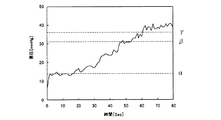
差圧演算手段10は、動脈側ドリップチャンバ5内の液圧と静脈側ドリップチャンバ6内の液圧との差を演算するものである。例えば、ダイアライザ3の膜面積が1.5[m2]、中空糸内径が210[μm]、容量(血液充填量)が91[mL]、血液回路を構成するチューブ内径が3.4[mm]、動脈側血液回路1の容量が63[mL]、静脈側血液回路2の容量が64[mL]、血液の温度が37[℃]、ヘマトクリットが32[%]、流量が100[mL/min]の如き条件においては、演算される差圧は、時間経過に伴い図2に示すように次第に上昇することが分かっている。
The differential pressure calculation means 10 calculates the difference between the hydraulic pressure in the arterial drip chamber 5 and the hydraulic pressure in the venous drip chamber 6. For example, the membrane area of the
即ち、プライミング液より血液の方が粘度が高いため、ダイアライザ3内をプライミング液が流れている間は、差圧演算手段10にて求められる差圧が低く、置換により血液がダイアライザ3内を流れ始めると、配管抵抗により、求められる差圧が高くなるのである。例えば、置換により血液がダイアライザ3の上流まで流れた際の差圧α[mmHg]、ダイアライザ3の下流まで流れた際の差圧β[mmHg]、及び血液がオーバーフローラインL2から排出されてしまう際の差圧γ[mmHg]を予め把握しておき、差圧演算手段10にて求められた差圧がβに達した時点を検知することで、血液回路の静脈側穿刺針b近傍(静脈側血液回路2の先端近傍であって第1電磁弁V1より上流側)におけるプライミング液から血液への置換を検知し得るようになっている。
That is, since the viscosity of blood is higher than that of the priming liquid, the differential pressure required by the differential pressure calculating means 10 is low while the priming liquid flows in the
切替制御手段12は、第1電磁弁V1及び第2電磁弁V2と電気的に接続され、これらの開閉を切替操作し得るものであり、差圧演算手段10にて求められた差圧がβに達したことを条件として、開状態の第2電磁弁V2を閉状態、閉状態の第1電磁弁V1を開状態に自動的に切り替えるよう制御するものである。かかる切替により、オーバーフローラインL2からの排出が遮断されつつ、体外循環がなされた血液が静脈側穿刺針bを介して患者の体内に戻るよう構成されている。 The switching control means 12 is electrically connected to the first electromagnetic valve V1 and the second electromagnetic valve V2, and can switch between opening and closing thereof. The differential pressure obtained by the differential pressure calculating means 10 is β On the condition that the first electromagnetic valve V2 in the open state is reached, the closed second electromagnetic valve V2 is automatically switched to the closed state, and the closed first electromagnetic valve V1 is automatically switched to the open state. By such switching, the blood from the extracorporeal circulation is returned to the patient's body via the venous puncture needle b while the discharge from the overflow line L2 is blocked.
従って、血液浄化治療開始時、静脈側穿刺針b近傍におけるプライミング液から血液への置換を目視で確認して手動操作にて第1電磁弁V1及び第2電磁弁V2を切替操作するものに比べ、作業性を良好とすることができるとともに、患者の体内に多量のプライミング液が入ってしまうのを回避し、且つ、体外循環した血液を確実に患者に戻すことができる。また、通常の透析装置においては、動脈側ドリップチャンバ5及び静脈側ドリップチャンバ6の液圧を透析装置本体8内の圧力センサにて計測しているので、既存の血液浄化装置における構成要素を流用してプライミング液から血液に置換されたことを差圧に基づいて検知でき、製造コストを抑制することができる。
Therefore, at the start of blood purification treatment, the replacement of the priming liquid with blood in the vicinity of the venous puncture needle b is visually confirmed, and the first solenoid valve V1 and the second solenoid valve V2 are switched manually. The workability can be improved, a large amount of priming liquid can be prevented from entering the patient's body, and the extracorporeally circulated blood can be reliably returned to the patient. Further, in a normal dialysis machine, the fluid pressure in the arterial drip chamber 5 and the venous drip chamber 6 is measured by a pressure sensor in the
ところで、差圧演算手段10にて求められた差圧がγに達した場合、血液がオーバーフローラインL2から排出されてしまうことを警告するよう構成してもよい。かかる警告手段として、例えばスピーカから警報を鳴らすもの、表示手段に警報を表示させるもの等何れのものであってもよい。また、図2で示すグラフを視認できるよう表示させ、差圧の傾向を医療従事者等に認識させるようにしてもよい。 By the way, when the differential pressure calculated | required in the differential pressure calculating means 10 reaches (gamma), you may comprise so that the blood may be discharged | emitted from the overflow line L2. As such a warning means, for example, those sound the alarm from the speaker may be of any such thing to display an alarm on the display means. Further, the graph shown in FIG. 2 may be displayed so as to be visible so that a medical worker or the like can recognize the tendency of the differential pressure.
タイマ11は、既述のように、透析治療開始(即ち、患者の血液の体外循環開始)からの経過時間を計測するものであり、置換により血液がダイアライザ3の上流まで流れるまでの時間(切替時間)を予め把握しておき、当該切替時間が経過したことを示す信号を切替制御手段12に送信し、該切替制御手段12にて開状態の第2電磁弁V2を閉状態、閉状態の第1電磁弁V1を開状態に自動的に切り替えるよう制御するものである。
As described above, the
即ち、何らかの機械的或いは電気的トラブルで、差圧演算手段10により適切な検知がなされない状態となったとしても、タイマ11による第1電磁弁V1及び第2電磁弁V2の強制的な切り替えを行わせることができ、タイマ11が所謂フェールセーフとして機能し得るようになっている。
That is, even if the mechanical pressure or the electrical pressure is not properly detected by the differential pressure calculation means 10 due to some mechanical or electrical trouble, the
次に、上記透析装置を用いた透析方法(血液浄化方法)について説明する。
上記したように、プライミング液で満たされた血液回路における動脈側血液回路1の先端に動脈側穿刺針a及び静脈側血液回路2の先端に静脈側穿刺針bをそれぞれ取り付け、それら穿刺針を患者に穿刺するとともに、第1電磁弁V1を閉状態、第2電磁弁V2及び第3電磁弁V3を開状態としておく。尚、生食ラインL1は、鉗子等により閉塞してある。
Next, a dialysis method (blood purification method) using the dialysis apparatus will be described.
As described above, the arterial puncture needle a and the venous puncture needle b are attached to the tip of the
そして、血液ポンプ4を駆動させることにより、透析治療が開始される。このとき、患者からの血液は、血液回路の上流側からプライミング液と置換されつつ下流側に流れ、ダイアライザ3にて浄化及び除水がなされることとなるとともに、予め満たされていたプライミング液は、静脈側ドリップチャンバ6にてオーバーフローし、オーバーフローラインL2を介して排出されることとなる。
And the dialysis treatment is started by driving the blood pump 4. At this time, the blood from the patient flows from the upstream side of the blood circuit to the downstream side while being replaced with the priming liquid, and purified and dehydrated by the
しかして、圧力センサ9にて動脈側ドリップチャンバ5及び静脈側ドリップチャンバ6内の液圧をリアルタイムに計測し、それらの差圧が差圧演算手段10にて逐次演算される。差圧演算手段10により演算された差圧がβ[mmHg]に達すると、切替制御手段12により、開状態の第2電磁弁V2を閉状態、閉状態の第1電磁弁V1を開状態に自動的に切り替えるよう制御する。
Accordingly, the
即ち、血液回路の静脈側穿刺b針近傍に、プライミング液が流れているとき、当該静脈側穿刺針bへのプライミング液の流れを遮断しつつ、オーバーフローラインL2にて排出するとともに、血液回路の静脈側穿刺針b近傍が、プライミング液から血液に置換されたことを差圧演算手段10にて検知したとき、オーバーフローラインL2からの排出を遮断しつつ、静脈側穿刺針bへの流れを許容するよう第1電磁弁V1及び第2電磁弁V2を自動的に切り替えるのである。 That is, when the priming liquid is flowing in the vicinity of the vein side puncture b needle of the blood circuit, the priming liquid flows to the vein side puncture needle b while being discharged through the overflow line L2, and the blood circuit When the pressure difference calculating means 10 detects that the vicinity of the venous puncture needle b has been replaced with blood from the priming solution, the flow to the venous puncture needle b is allowed while blocking the discharge from the overflow line L2. Thus, the first electromagnetic valve V1 and the second electromagnetic valve V2 are automatically switched.
上記実施形態によれば、プライミング時などに必要とされたオーバーフローラインL2を透析治療時(血液浄化治療時)にも使用することができ、既存の血液浄化装置における構成要素を流用することができるので、製造コストを抑制することができる。 According to the above embodiment, the overflow line L2 required for priming or the like can be used also during dialysis treatment (during blood purification treatment), and the components in the existing blood purification device can be diverted. Therefore, manufacturing cost can be suppressed .
以上、本実施形態について説明したが、本発明はこれに限定されるものではない。 Having described the present embodiment, the present invention is not name limited thereto.
尚、本実施形態においては、透析治療時に用いられる透析装置に適用しているが、患者の血液を体外循環させつつ浄化し得る他の装置(例えば血液濾過透析法、血液濾過法、AFBFで使用される血液浄化装置、血漿吸着装置など)に適用してもよい。 In this embodiment, the present invention is applied to a dialysis apparatus used at the time of dialysis treatment, but is used in other apparatuses that can purify the patient's blood while circulating it outside the body (for example, blood filtration dialysis, blood filtration, AFBF). The present invention may be applied to blood purification devices, plasma adsorption devices, and the like.
静脈側血液回路の先端近傍に、プライミング液が流れているとき、当該静脈側血液回路の先端へのプライミング液の流れを遮断しつつ、静脈側血液回路の先端近傍から延設された排出ラインにて排出するとともに、静脈側血液回路の先端近傍が、プライミング液から血液に置換されたことを検知手段にて検知したとき、排出ラインからの排出を遮断しつつ、静脈側血液回路の先端への流れを許容するよう自動的に切り替えるよう構成され、動脈側血液回路及び静脈側血液回路には、プライミング液及び血液の除泡を図るための動脈側ドリップチャンバ及び静脈側ドリップチャンバがそれぞれ設けられるとともに、排出ラインは当該静脈側ドリップチャンバの空気層側から延びるオーバーフローラインから成るものとされ、且つ、検知手段は、動脈側ドリップチャンバ内の液圧と静脈側ドリップチャンバ内の液圧との差圧に基づき、静脈側血液回路の先端近傍であって第1弁より上流側におけるプライミング液から血液への置換を検知する血液浄化装置であれば、他の形態及び用途のものにも適用することができる。 When priming fluid is flowing near the tip of the venous blood circuit, the priming fluid flows to the drain line extending from the tip of the venous blood circuit while blocking the flow of priming fluid to the tip of the venous blood circuit. When the detection means detects that the vicinity of the tip of the venous blood circuit has been replaced with blood from the priming liquid, the discharge to the tip of the venous blood circuit is interrupted while blocking the discharge from the discharge line. The arterial blood circuit and the venous blood circuit are provided with an arterial drip chamber and a venous drip chamber for defoaming the priming fluid and blood, respectively. The discharge line is composed of an overflow line extending from the air layer side of the venous drip chamber, and the detection means includes: Based on the differential pressure between the fluid pressure in the pulmonary drip chamber and the fluid pressure in the venous drip chamber, the replacement of the priming fluid with blood is detected near the tip of the venous blood circuit and upstream of the first valve. if blood purification equipment that can be applied to those other forms and applications.
1 動脈側血液回路
2 静脈側血液回路
3 ダイアライザ(血液浄化手段)
4 血液ポンプ
5 動脈側ドリップチャンバ
6 静脈側ドリップチャンバ
7 生食バッグ
8 透析装置本体
9 圧力センサ
10 差圧演算手段(検知手段)
11 タイマ
12 切替制御手段
a 動脈側穿刺針
b 静脈側穿刺針
L1 生食ライン
L2 オーバーフローライン(排出ライン)
V1 第1電磁弁(第1弁)
V2 第2電磁弁(第2弁)
V3 第3電磁弁
1
4 Blood Pump 5 Arterial Drip Chamber 6 Vein Side Drip Chamber 7
11
V1 1st solenoid valve (1st valve)
V2 Second solenoid valve (second valve)
V3 3rd solenoid valve
Claims (2)
該血液回路の動脈側血液回路及び静脈側血液回路の間に介装されて当該血液回路を流れる血液を浄化する血液浄化手段と、
前記静脈側血液回路先端近傍を開閉可能として設けられ、当該静脈側血液回路先端から患者に流れるプライミング液及び血液を遮断又は許容する第1弁と、
前記血液回路における第1弁より上流側から延設され、当該血液回路を流れるプライミング液を排出し得る排出ラインと、
該排出ラインを開閉可能として設けられ、当該排出ラインを流れるプライミング液及び血液の流れを遮断又は許容する第2弁と、
を具備した血液浄化装置であって、
前記静脈側血液回路の先端近傍であって前記第1弁より上流側が、プライミング液から血液に置換されたことを検知する検知手段を有し、該検知手段による置換の検知がなされることにより、閉状態の前記第1弁を開状態、及び開状態の前記第2弁を閉状態に自動的に切り替えるよう構成され、前記動脈側血液回路及び静脈側血液回路には、プライミング液及び血液の除泡を図るための動脈側ドリップチャンバ及び静脈側ドリップチャンバがそれぞれ設けられるとともに、前記排出ラインは当該静脈側ドリップチャンバの空気層側から延びるオーバーフローラインから成るものとされ、且つ、前記検知手段は、前記動脈側ドリップチャンバ内の液圧と静脈側ドリップチャンバ内の液圧との差圧に基づき、前記静脈側血液回路の先端近傍であって前記第1弁より上流側におけるプライミング液から血液への置換を検知することを特徴とする血液浄化装置。 A blood circuit comprising an arterial blood circuit and a venous blood circuit, prefilled with a priming solution, and capable of circulating the patient's blood extracorporeally from the distal end of the arterial blood circuit to the distal end of the venous blood circuit;
A blood purification means for purifying blood flowing between the arterial blood circuit and the venous blood circuit of the blood circuit and flowing through the blood circuit;
A first valve that is provided so as to be openable and closable near the venous blood circuit tip, and that blocks or allows priming fluid and blood flowing from the venous blood circuit tip to the patient;
A discharge line extending from the upstream side of the first valve in the blood circuit and capable of discharging the priming fluid flowing through the blood circuit;
A second valve provided to be capable of opening and closing the discharge line, and blocking or allowing a flow of priming liquid and blood flowing through the discharge line;
A blood purification apparatus comprising:
In the vicinity of the distal end of the venous blood circuit, the upstream side of the first valve has detection means for detecting that the priming liquid has been replaced with blood, and the detection of the replacement by the detection means, The first valve in the closed state is automatically switched to the open state, and the second valve in the open state is automatically switched to the closed state. The arterial blood circuit and the venous blood circuit are configured to remove priming fluid and blood. An arterial drip chamber and a venous drip chamber for foaming are respectively provided, the discharge line is composed of an overflow line extending from the air layer side of the venous drip chamber, and the detection means includes: Based on the differential pressure between the fluid pressure in the arterial drip chamber and the fluid pressure in the venous drip chamber, it is near the tip of the venous blood circuit. Blood purification apparatus and detecting the substitution of the blood from the priming liquid on the upstream side of the first valve.
Priority Applications (4)
| Application Number | Priority Date | Filing Date | Title |
|---|---|---|---|
| JP2005091983A JP4716409B2 (en) | 2005-03-28 | 2005-03-28 | Blood purification equipment |
| PCT/JP2006/304316 WO2006103883A1 (en) | 2005-03-28 | 2006-03-07 | Blood depurator and depurating method |
| EP06728685A EP1875931B1 (en) | 2005-03-28 | 2006-03-07 | Blood depurator |
| US11/391,164 US7935249B2 (en) | 2005-03-28 | 2006-03-27 | Blood purification apparatus and method for blood purification |
Applications Claiming Priority (1)
| Application Number | Priority Date | Filing Date | Title |
|---|---|---|---|
| JP2005091983A JP4716409B2 (en) | 2005-03-28 | 2005-03-28 | Blood purification equipment |
Publications (3)
| Publication Number | Publication Date |
|---|---|
| JP2006271514A JP2006271514A (en) | 2006-10-12 |
| JP2006271514A5 JP2006271514A5 (en) | 2007-11-22 |
| JP4716409B2 true JP4716409B2 (en) | 2011-07-06 |
Family
ID=37034131
Family Applications (1)
| Application Number | Title | Priority Date | Filing Date |
|---|---|---|---|
| JP2005091983A Expired - Fee Related JP4716409B2 (en) | 2005-03-28 | 2005-03-28 | Blood purification equipment |
Country Status (4)
| Country | Link |
|---|---|
| US (1) | US7935249B2 (en) |
| EP (1) | EP1875931B1 (en) |
| JP (1) | JP4716409B2 (en) |
| WO (1) | WO2006103883A1 (en) |
Families Citing this family (16)
| Publication number | Priority date | Publication date | Assignee | Title |
|---|---|---|---|---|
| US7713226B2 (en) * | 2006-01-06 | 2010-05-11 | Renal Solutions, Inc. | On demand and post-treatment delivery of saline to a dialysis patient |
| US8444587B2 (en) | 2007-10-01 | 2013-05-21 | Baxter International Inc. | Fluid and air handling in blood and dialysis circuits |
| US8123947B2 (en) | 2007-10-22 | 2012-02-28 | Baxter International Inc. | Priming and air removal systems and methods for dialysis |
| US8114276B2 (en) | 2007-10-24 | 2012-02-14 | Baxter International Inc. | Personal hemodialysis system |
| JP4281835B2 (en) * | 2007-11-06 | 2009-06-17 | 株式会社ジェイ・エム・エス | Hemodialysis machine |
| JP5276909B2 (en) * | 2008-06-24 | 2013-08-28 | 日機装株式会社 | Blood purification equipment |
| JP5426269B2 (en) * | 2009-08-04 | 2014-02-26 | 日機装株式会社 | Blood circuit and blood purification apparatus having the same |
| AU2010338448B2 (en) | 2009-12-17 | 2014-01-23 | Gambro Lundia Ab | System and method for monitoring the presence of blood |
| JP2012000319A (en) * | 2010-06-18 | 2012-01-05 | Nipro Corp | Negative pressure detector |
| EP2714130A1 (en) * | 2011-05-31 | 2014-04-09 | Gambro Lundia AB | Method and device for detecting configurations of extracorporeal blood circuit, apparatus comprising detecting device, and computer program for performing the method |
| EP2583702B1 (en) * | 2011-10-20 | 2015-09-02 | D_MED Consulting AG | Method for ending haemodialysis |
| CN102657903B (en) * | 2012-05-18 | 2015-07-29 | 重庆山外山科技有限公司 | A kind of blood purification bubble monitoring system |
| DE102013011715A1 (en) * | 2013-07-15 | 2015-01-15 | Fresenius Medical Care Deutschland Gmbh | A method of controlling a blood treatment device and devices |
| DE102014011673A1 (en) * | 2014-08-05 | 2016-02-11 | Fresenius Medical Care Deutschland Gmbh | Process for washing out gas bubbles in an extracorporeal blood circulation |
| US9486590B2 (en) | 2014-09-29 | 2016-11-08 | Fenwal, Inc. | Automatic purging of air from a fluid processing system |
| DE102018116806A1 (en) * | 2018-07-11 | 2020-01-16 | Fresenius Medical Care Deutschland Gmbh | Control and / or regulating device for removing fluid from a blood filter |
Citations (4)
| Publication number | Priority date | Publication date | Assignee | Title |
|---|---|---|---|---|
| JP2002325837A (en) * | 2000-06-15 | 2002-11-12 | Nefuronetto:Kk | Automatic blood dialyzer system |
| JP2003265602A (en) * | 2002-03-20 | 2003-09-24 | Nikkiso Co Ltd | Blood circuit |
| JP2004187990A (en) * | 2001-12-18 | 2004-07-08 | Kita Kyushu Biophysics Kenkyusho:Kk | Automatic blood dialysing apparatus and priming method using the same |
| JP2004524083A (en) * | 2001-02-07 | 2004-08-12 | ネフロス・インコーポレーテッド | Method and apparatus for a hemodiafiltration delivery module |
Family Cites Families (4)
| Publication number | Priority date | Publication date | Assignee | Title |
|---|---|---|---|---|
| FR2672218B1 (en) * | 1991-02-06 | 1998-04-24 | Hospal Ind | DEVICE AND METHOD FOR LEVELING A LIQUID IN A CHAMBER OF AN EXTRACORPOREAL BLOOD CIRCUIT. |
| US5336165A (en) * | 1991-08-21 | 1994-08-09 | Twardowski Zbylut J | Artificial kidney for frequent (daily) Hemodialysis |
| DE19848235C1 (en) * | 1998-10-20 | 2000-03-16 | Fresenius Medical Care De Gmbh | Method for monitoring supply to vessel and extra-corporeal blood treatment device for monitoring supply to vessel; inputs blood circulation pressure to computer to calculate values to identify errors in supply during dialysis |
| JP4853956B2 (en) * | 2006-04-05 | 2012-01-11 | 日機装株式会社 | Blood circuit priming method |
-
2005
- 2005-03-28 JP JP2005091983A patent/JP4716409B2/en not_active Expired - Fee Related
-
2006
- 2006-03-07 WO PCT/JP2006/304316 patent/WO2006103883A1/en active Application Filing
- 2006-03-07 EP EP06728685A patent/EP1875931B1/en not_active Not-in-force
- 2006-03-27 US US11/391,164 patent/US7935249B2/en not_active Expired - Fee Related
Patent Citations (4)
| Publication number | Priority date | Publication date | Assignee | Title |
|---|---|---|---|---|
| JP2002325837A (en) * | 2000-06-15 | 2002-11-12 | Nefuronetto:Kk | Automatic blood dialyzer system |
| JP2004524083A (en) * | 2001-02-07 | 2004-08-12 | ネフロス・インコーポレーテッド | Method and apparatus for a hemodiafiltration delivery module |
| JP2004187990A (en) * | 2001-12-18 | 2004-07-08 | Kita Kyushu Biophysics Kenkyusho:Kk | Automatic blood dialysing apparatus and priming method using the same |
| JP2003265602A (en) * | 2002-03-20 | 2003-09-24 | Nikkiso Co Ltd | Blood circuit |
Also Published As
| Publication number | Publication date |
|---|---|
| WO2006103883A1 (en) | 2006-10-05 |
| US20060213835A1 (en) | 2006-09-28 |
| US7935249B2 (en) | 2011-05-03 |
| JP2006271514A (en) | 2006-10-12 |
| EP1875931A1 (en) | 2008-01-09 |
| EP1875931B1 (en) | 2011-08-24 |
| EP1875931A4 (en) | 2010-07-28 |
Similar Documents
| Publication | Publication Date | Title |
|---|---|---|
| JP4716409B2 (en) | Blood purification equipment | |
| JP5914106B2 (en) | Blood purification equipment | |
| JP4798653B2 (en) | Blood purification equipment | |
| EP2752210B1 (en) | Blood purification device | |
| JP5231967B2 (en) | Blood purification equipment | |
| WO2006038396A1 (en) | Blood purifying device | |
| US20180036470A1 (en) | Blood Purification Apparatus | |
| WO2016186163A1 (en) | Blood purification device | |
| JP6437349B2 (en) | Blood purification equipment | |
| WO2016143841A1 (en) | Blood purification device | |
| JP5231964B2 (en) | Blood purification equipment | |
| JP5778004B2 (en) | Blood purification equipment | |
| JP6062580B2 (en) | Blood purification equipment | |
| JP6017711B2 (en) | Blood purification equipment | |
| JP6017712B2 (en) | Blood purification equipment | |
| JP6475284B2 (en) | Blood purification equipment | |
| JP6613266B2 (en) | Blood purification equipment | |
| JP2009297340A (en) | Blood purifying device | |
| JP6017713B2 (en) | Blood purification equipment | |
| JP2017099441A (en) | Blood purification device | |
| WO2023032960A1 (en) | Blood purification device |
Legal Events
| Date | Code | Title | Description |
|---|---|---|---|
| A521 | Request for written amendment filed |
Free format text: JAPANESE INTERMEDIATE CODE: A523 Effective date: 20071010 |
|
| A621 | Written request for application examination |
Free format text: JAPANESE INTERMEDIATE CODE: A621 Effective date: 20071128 |
|
| A131 | Notification of reasons for refusal |
Free format text: JAPANESE INTERMEDIATE CODE: A131 Effective date: 20100726 |
|
| A521 | Request for written amendment filed |
Free format text: JAPANESE INTERMEDIATE CODE: A523 Effective date: 20100915 |
|
| TRDD | Decision of grant or rejection written | ||
| A01 | Written decision to grant a patent or to grant a registration (utility model) |
Free format text: JAPANESE INTERMEDIATE CODE: A01 Effective date: 20110323 |
|
| A01 | Written decision to grant a patent or to grant a registration (utility model) |
Free format text: JAPANESE INTERMEDIATE CODE: A01 |
|
| A61 | First payment of annual fees (during grant procedure) |
Free format text: JAPANESE INTERMEDIATE CODE: A61 Effective date: 20110325 |
|
| R150 | Certificate of patent or registration of utility model |
Free format text: JAPANESE INTERMEDIATE CODE: R150 |
|
| FPAY | Renewal fee payment (event date is renewal date of database) |
Free format text: PAYMENT UNTIL: 20140408 Year of fee payment: 3 |
|
| R250 | Receipt of annual fees |
Free format text: JAPANESE INTERMEDIATE CODE: R250 |
|
| LAPS | Cancellation because of no payment of annual fees |