JP4707914B2 - Energy recovery device and method in paper machine - Google Patents
Energy recovery device and method in paper machine Download PDFInfo
- Publication number
- JP4707914B2 JP4707914B2 JP2001545639A JP2001545639A JP4707914B2 JP 4707914 B2 JP4707914 B2 JP 4707914B2 JP 2001545639 A JP2001545639 A JP 2001545639A JP 2001545639 A JP2001545639 A JP 2001545639A JP 4707914 B2 JP4707914 B2 JP 4707914B2
- Authority
- JP
- Japan
- Prior art keywords
- forming
- guide plate
- water
- turbine
- fabric
- Prior art date
- Legal status (The legal status is an assumption and is not a legal conclusion. Google has not performed a legal analysis and makes no representation as to the accuracy of the status listed.)
- Expired - Lifetime
Links
Images


Classifications
-
- D—TEXTILES; PAPER
- D21—PAPER-MAKING; PRODUCTION OF CELLULOSE
- D21F—PAPER-MAKING MACHINES; METHODS OF PRODUCING PAPER THEREON
- D21F9/00—Complete machines for making continuous webs of paper
- D21F9/003—Complete machines for making continuous webs of paper of the twin-wire type
-
- D—TEXTILES; PAPER
- D21—PAPER-MAKING; PRODUCTION OF CELLULOSE
- D21F—PAPER-MAKING MACHINES; METHODS OF PRODUCING PAPER THEREON
- D21F1/00—Wet end of machines for making continuous webs of paper
-
- D—TEXTILES; PAPER
- D21—PAPER-MAKING; PRODUCTION OF CELLULOSE
- D21F—PAPER-MAKING MACHINES; METHODS OF PRODUCING PAPER THEREON
- D21F1/00—Wet end of machines for making continuous webs of paper
- D21F1/66—Pulp catching, de-watering, or recovering; Re-use of pulp-water
-
- Y—GENERAL TAGGING OF NEW TECHNOLOGICAL DEVELOPMENTS; GENERAL TAGGING OF CROSS-SECTIONAL TECHNOLOGIES SPANNING OVER SEVERAL SECTIONS OF THE IPC; TECHNICAL SUBJECTS COVERED BY FORMER USPC CROSS-REFERENCE ART COLLECTIONS [XRACs] AND DIGESTS
- Y02—TECHNOLOGIES OR APPLICATIONS FOR MITIGATION OR ADAPTATION AGAINST CLIMATE CHANGE
- Y02P—CLIMATE CHANGE MITIGATION TECHNOLOGIES IN THE PRODUCTION OR PROCESSING OF GOODS
- Y02P70/00—Climate change mitigation technologies in the production process for final industrial or consumer products
- Y02P70/10—Greenhouse gas [GHG] capture, material saving, heat recovery or other energy efficient measures, e.g. motor control, characterised by manufacturing processes, e.g. for rolling metal or metal working
Abstract
Description
【0001】
〔技術分野〕
本発明は、支持部材の凸形面に沿って湾曲した少なくとも1つのループ状形成ファブリックを含む、フォーミングセクション即ち形成セクションの形成帯域内に、ヘッドボックスからのストックを供給し、水が形成帯域の少なくとも1つの形成ファブリックを通り抜けるように水をストックから排水して、紙又は板紙のウエブを形成し、少なくとも1つのファブリックを通り抜けた水が形成帯域から放出され、その水が運動エネルギーを得る、抄紙機又は板紙抄紙機の形成セクション内のエネルギーの回収方法に関する。更に、本発明は、抄紙機又は板紙抄紙機内の装置に関する。
【0002】
〔技術の状態〕
今日、紙又は板紙、特にティシュー紙、新聞紙、雑誌用紙は、非常に高速で生産される。ティシューについて、今日、抄紙機の速度は、2000m/minに達する。ファブリックウエブを、例えばダブルワイヤフォーマーで形成するとき、ストックが2つの形成クロージングの間に注入され、これらの形成クロージングは両方とも、形成ロールのようなワイヤ支持体を動かす。外側のクロージングは、水に対して浸透性のあるワイヤである。更なる加工のために、その他のクロージング(例えばフェルト又はワイヤ)がウエブを搬送するようになっている。ストックは、0.1乃至0.5%の繊維濃度を有し、流量は、断面方向又は幅方向1メートル当たり約0.5m3/secである。ウエブの形成は、外側の可撓性ファブリック、即ち、ワイヤを通り抜けて排水されるストック内の水によって起こり、ストックは、その水の少量部分だけが繊維ウエブによって繊維ウエブの上で搬送される。水は、形成ロールに押し付けるようにリードロールが予備引張り即ちテンションを与えるワイヤによって付与される静圧によって搾り出される。上述の力のため、ワイヤから放出される水は、理論的に且つ標準的には、形成ロールの周速よりも速い速度を有する。例えば、標準的な大きさ(幅6メートル)のティシュー機では、莫大な量の水が排水されるので、排水流量は、約3m3/secになり、大量のエネルギーが抄紙機のこの箇所で放出されることが理解される。従来、このエネルギーは、少なくともその運動エネルギー部分を除き、全く回収されておらず、運動エネルギーも、再循環のためにホワイトウォータートレイ内に収集されていたに過ぎなかった。単一のワイヤ及び形成ロールを使用するシングルワイヤフォーマー又は形成ロールを必要としないブレードフォーマー型の形成セクションに関しても、同じ問題が関係している。
【0003】
〔発明の概要〕
本発明の目的は、抄紙機内で排水されるホワイトウォーターの運動エネルギーの大部分を回収する方法及び装置によって、上述の不利益を最小にすることにある。これは、支持部材の凸面に沿って湾曲した少なくとも1つのループ状形成ファブリックを含む、形成セクションの形成帯域に、ヘッドボックスからのストックを供給する段階と、水をストックから形成帯域の少なくとも1つの形成ファブリックを通り抜けるようにして排水し、紙又は板紙ウエブを形成する段階と、少なくとも1つのファブリックを通り抜けた水を形成帯域から放出し、その水が運動エネルギーを得る段階と、を有する抄紙機又は板紙抄紙機の形成セクションのエネルギー回収方法であって、形成帯域から放出された水の中に可動構成要素を配置して、水により可動構成要素を動かし、それにより、運動エネルギーの一部分を回収する段階とを有し、回収されたエネルギーを、発電機のような別の装置又はユニットを駆動するように接続するエネルギー回収方法によって達成される。
【0004】
本発明により、膨大な量のエネルギーを、ウエブの形成に関連する脱水工程中にストックから取出される水の運動エネルギーから回収することができる。幅6mのヘッドボックスと1800m/minの機械速度を有するティシュー用ツインワイヤ抄紙機について、800kWまでのエネルギーを回収することが計算で示されており、それにより、約2百万SEK/年の節約を実現する。本発明のコストが比較的適当であるので、電気の価格に依存して、支払期間を非常に短くすることができる。
【0005】
本発明の更なる側面は、以下のとおりである。
【0006】
更に、可動構成要素として使用するためのタービン、好ましくは、反動タービンを準備する段階と、このタービンが形成帯域から放出された水、好ましくは、少なくとも1つの形成ファブリックを通り抜けた水によって回転されるように、タービンを取付ける段階とを有する。
【0007】
支持部材の凸面に沿って湾曲し且つ収斂する形成帯域を構成する2つのループ状形成ファブリックをツインワイヤフォーマー内に設ける段階と、支持部材の凸面に関連した形成帯域の2つのファブリックのうちの少なくとも外側のファブリックを通り抜けるようにして水をストックから排水し、紙又は板紙ウエブ(W)を形成する段階と、可動構成要素を形成ファブリックの外側ファブリックのループの内側に取付ける段階と、を有する。
【0008】
支持部材に含まれる回転可能な形成ロールの上に、2つの形成ファブリックを支持する段階を有する。
【0009】
形成ファブリックを支持するための支持凸面を有し且つ支持部材に含まれる形成シューの上に、2つの形成ファブリックを支持する段階を有する。
【0010】
更に、抄紙機方向に互いに間隔を隔てた一連の湾曲した脱水ブレードの上に、2つの形成ファブリックを支持する段階を有し、脱水ブレードは、支持部材及びその支持凸面内に含まれる。
【0011】
少なくとも1つの案内プレートが、移動中の水をタービンの中に案内する。
【0012】
水が、案内プレートの主要部分にわたる湾曲経路に沿って移動する。
【0013】
湾曲経路の主要部分の半径(R2)は、ほぼ一定であり、形成ロールの半径(R1)よりも大きく且つR1の120%よりも小さい、即ち、R1<R2<R1x1,2である。
【0014】
案内プレートのなす角度(γ)は、形成ロールの周囲の20乃至90°を覆う。
【0015】
形成ロールは、表面に孔を有する真空ロールであり、案内プレート(16)のなす角度は、20乃至50°、好ましくは、25乃至40°である。
【0016】
形成ロールは、不浸透表面を有し、案内プレートのなす角度γは、40乃至80°、好ましくは、50乃至70°である。
【0017】
ウエブ(W)の速度は、1000m/minよりも速く、好ましくは、1500m/minよりも速く、更に好ましくは、1800m/minよりも速い。
【0018】
少なくとも0,2m3/sec/m、好ましくは、0,3m3/sec、更に好ましくは、0,4m3がワイヤを通り抜けて搾り出される。
【0019】
運動エネルギーを電気エネルギーに変換する発電機を使用し、好ましくは、電気エネルギーをポンプに供給し、更に好ましくは、電気エネルギーをストックポンプに供給する。
【0020】
本発明はまた、特許請求の範囲の請求項1に記載のエネルギー回収方法を実施するための、抄紙機又は板紙抄紙機内の装置であって、ストックを供給するヘッドボックスと、形成帯域と、を有し、この形成帯域は、少なくとも1つのループ状形成ファブリックと、凸面を有する支持部材と、を含み、ループ状形成ファブリックは、支持部材の凸面の一部分を走行し、それにより、紙又は板紙ウエブが形成される形成帯域を定めるように構成され、ストックを、ヘッドボックスによって形成帯域内に供給し、水を形成帯域内でストックから少なくとも1つのループ状形成ファブリックを通り抜けるようにして排水し、紙又は板紙ウエブを形成し、少なくとも1つのループ状形成ファブリックを通り抜けた水を形成帯域から放出し、その水が運動エネルギーを得る装置において、ストックから排水された水の運動エネルギーの少なくともいくらかを回収する可動構成要素が、形成帯域に隣接して位置決めされ、それにより、可動構成要素が、回収された運動エネルギーを別の装置/ユニットを駆動することに変換する装置に関する。
【0021】
本発明の更なる側面は以下のとおりである。
【0022】
タービンは、反動型であり、好ましくは、バンキタービンである。
【0023】
ワイヤを通り抜けてタービン内に搾り出された移動中の水を案内するための案内装置が設けられる。
【0024】
案内装置は、形成ロールの周囲と近接関係をなして位置決めされた案内プレートを有する。
【0025】
案内プレートの主要部分は、実質的に一定の半径R2を有し、この半径R2は、形成ロールの半径R1と等しいか、或いは、それよりも大きく、好ましくは、R1<R2<R1x1,2である。
【0026】
案内プレートは、上流端及び下流端を有し、上流端箇所16Aと下流端箇所16Bとの間の角度γは、20乃至90°、好ましくは、30乃至70°である。
【0027】
可撓性ファブリックの角度αは、ワイヤの角度βよりも大きく、案内プレートの角度γは、ワイヤの角度βよりも小さい。
【0028】
案内装置は、案内プレートの下流に第2の案内プレートを有し、この第2の案内プレートは、案内プレートの断面方向長さよりも実質的に短い断面方向長さを有する。
【0029】
第2の案内プレートは、湾曲し、その曲率は、案内プレートの曲率と反対である。
【0030】
タービンの軸線方向長さは、ワイヤの軸線方向長さとほぼ同じであり、このワイヤの軸線方向長さは、形成帯域の軸線方向長さとほぼ同じである。
【0031】
タービンの外径φTは、形成ロールの半径R1よりも実質的に小さく、好ましくは、R1x0,5<φT<R1x0,9である。
【0032】
タービンは、その軸線が形成ロールの軸線と平行に位置決めされ、タービン及び形成ロールは、タービンの周囲と形成ロールの周囲との間の最小距離が5乃至700mm、好ましくは、5乃至200mmになるような関係に位置決めされる。
【0033】
タービンのシャフトは、発電機、好ましくは、三相同期電動機に連結される。
【0034】
以下、添付図面を参照して、本発明を更に詳細に説明する。
【0035】
〔発明の詳細な説明〕
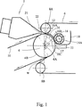
本発明は、すべての種類のダブルワイヤフォーマー、即ち、2つのクロージング(例えば、排水能力の要望に依存して、2つのワイヤでも良いし、1つのワイヤとフェルトでも良い)が形成ロールのような形成ユニットの周りの一番上を走行するフォーマーと共に使用するのが良い。図1には、いわゆるクレセントフォーマーが示され、クレセントフォーマーは、ヘッドボックス2と、形成ロール4と、ワイヤ6と、フェルト10とを有する。形成ロール4は、軸線4Aを中心に回転する。フェルト10は、180°よりも僅かに大きい接触角度αで形成ロール4の外面4Bと接触した状態で形成ロール4の周りを走行する。ワイヤ6は、180°よりも小さい接触角度βをなしてフェルト10の上で形成ロール4の周りを走行する。ワイヤ6は、上側案内ロール8A及び下側案内ロール8Bによって、形成ロール4の外面4Bの上でフェルトに押し付けられる。ヘッドボックス2は、ストック21をヘッドボックス2の排出開口22から、ワイヤ6がフェルト10に出会うところに形成されたニップ12の中に注入する。本発明によれば、タービン14が、形成ロール4の周囲に極めて近接して位置決めされる。形成ロール4の半径R1よりも僅かに大きい半径R2を有する案内プレート16(図2参照)が、ニップ12とタービン14との間に且つ形成ロール4よりも上の所定距離のところに位置決めされる。案内プレートの角度γは、約35°であり、その上流縁16Aは、ニップ12に近接して位置決めされ、その下流端16Bは、タービン14に近接して位置決めされる。形成ロール4の周囲に近接したタービン14の下流には、第2の案内プレート17が、タービン14よりも後方及びその下に位置決めされる。タービンの軸14Aは、好ましくは伝動装置(図示せず)によって、発電機11(概略的に図示)に連結される。タービン14は、反動型のものであり、好ましくは、いわゆるバンキ(Banki)タービンであり、このタービンは、その機能によりクロスフロー(交差流)タービンとも称される。この型式のタービンは、本発明の場合のような比較的高速で移動している水からエネルギーを回収するのに非常に適しているので、この型式のタービンは、本発明による装置に対して特に適している。案内プレート16は、形成ロール4の半径R1よりも僅かに大きい一定の曲率R2を有し、この曲率R2は、好ましくは、形成ロール4の半径R1の1.5倍である。案内プレート16は、その凹面16Cがワイヤ6の面よりも約20乃至50mm上に位置決めされるように位置決めされ、凹面16Cに沿って水が案内される。ホワイトウォータートレイ18が設けられる。
【0036】
本発明による装置の機能は、以下のとおりである。形成セクションのフェルト10及びワイヤ6を所定速度、例えば1500m/minで走行させているとき、ヘッドボックス2の排出開口22によってストック21を注入する。ストックをニップ12内に供給し、その後、ストックを形成ロール4の周りの2つのクロージング6、10の間に導く。これに関して、ストック21内に含有されているほとんどの量の水が、ワイヤ6の引張り又はテンションによってワイヤ6を通り抜けるようにして搾り出される。その結果、搾り出された水は、形成ロール4の周速よりも僅かに速い速度を有する。周速が30m/minであれば、水滴の速度が約30.4m/minになることを試験が示している。図1に使用されているような不浸透表面を有するロールについては、ニップ12から始まる約60°の角度方向の帯域に沿って、脱水が起こる。脱水される水量は、最初の10°の間が最も大きく、それから僅かに減少する。水滴は、できるだけ乱流を生じさせないように形成された案内プレート16の湾曲面16Cの上に収集され、このことは、できるだけ不規則でない面16Cを有し且つ一定の曲率を使用することによって達成される。水は、案内プレート16に沿って集まり、最終的には、できるだけ多くの運動エネルギーを回収するような最適流れ方向でタービン14の中に案内される。クロスフロータービン(例えば、バンキタービン)14については、運動エネルギーの約80%が、タービンへの流入中に回収され、運動エネルギーの約20%が、タービンからの流出中に回収される。このクロスフロー機能は、バンキタービンが特に適当であることの理由である。更なる量の水をタービン14内に案内するために、タービン14の下流には、第1の案内プレート16に対して逆の曲率を有する第2の案内プレート17が設けられる。水によって引き起こされるタービン14の回転は、その軸14Aによって伝動装置(図示せず)に伝達され、その後、電気エネルギーを生産する発電機に伝動される。最も多くの適用例において、タービン14の回転速度を発電機11の最適な回転速度に変換する伝動装置が好ましい。状況しだいで、種々の種類の発電機、例えば、交流発電機又は直流発電機を使用しても良いことが明らかである。
【0037】
好ましい実施形態では、発電機11によって生産された電力は、ストックをヘッドボックス2に供給するポンプ(図示せず)に供給される。
【0038】
本発明の成果として、大量のエネルギーを回収することができる。最適化された装置であれば、全体的な歩留まりは、約60%である。ストック流量が断面方向又は幅方向1メートル当たり約0.5m3/secであれば、6メートル幅の機械について回収することができる電力は、約810kWである。0.30SEK/kWの価格であれば、1年当たりの作動を350日とすると、年間約2MSEKの節約をもたらす。本発明の更なる側面、例えば、環境へのやさしさを考えると、本発明の功績は、驚くほど明確であることが認識される。
【0039】
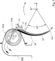
図2は、本発明による実施形態の詳細図である。本発明の基本原理は、装置の姿勢及びフェルト10の代わりに第2のワイヤを使用していること以外、図1の基本原理と全く同じである。図2では、ヘッドボックス2は、形成ロール4の中心4Aの下に位置決めされ、注入排出開口22は、上方に差し向けられている。形成ロールの半径R1は、760mmである。案内プレート16の半径R2は、一定であり、約810mmである。案内プレート16の一定の曲率の中心は、形成ロールの中心4Aに対してオフセットされ、即ち、形成ロール4の中心4Aよりも50mm上にある。案内プレートと形成ロール(ワイヤ6)の周囲との間の最短距離l1は、約35mmである。案内プレート16の曲率中心16Eのオフセット配置のため、案内プレートと形成ロール(ワイヤ6)の周囲との間の距離は、上方に増大し続ける。タービン14と形成ロール4の周囲4Bとの間の距離は、約50mmである(通常、この距離は、10乃至100mmにあるべきであり、好ましくは、20乃至70mmにある。)。
【0040】
実質的に平らな第2の案内プレート17は、その縁17Aが形成ロール4の周囲4Bに近接するように、例えば、縁17Aとワイヤ6との間が約6mmであるように位置決めされる。第2の案内プレート17の断面方向長さl2は、約50mmである(しかしながら、第2の案内プレート17の幅は、通常、タービンと同じである。)。従って、第1の案内プレート16は、タービン14内を移動中の水の大部分を、案内プレートの下流端16Bの位置において、その位置におけるタービンブレードの角度に適合させた第1方向に差し向ける。第2の案内プレート17の延長方向は、その位置におけるタービンブレードの最適角度に適合する。タービン14の周りには、ハウジング19が設けられる。ハウジングは、いくつかの部分、即ち、最も内側の上側部分19A、最も外側の下側部分19B、最も下側の内側部分19C及び最も下側のベース部分19Dを有する。これらの種々の部分は、フランジ19Fによって互いに取付けられている。抄紙機のホワイトウォータートレイ18にハウジングを取付けるためのフランジ19Eが、ハウジング19の底部にある。(案内プレート16の下流に位置決めされている)ハウジングの最も上側の部分19Aは、水を接触の仕方で案内するために、タービンの周囲14Bの大部分を包囲するようにそれから短い距離のところに合せられており、このことは、図3に関連して更に説明する。直径φTは、500mmである。タービンの内径φIは、340mmである。
【0041】
図3は、タービン14が形成ロール4から更に遠くに位置決めされていること以外、図2と同様の実施形態を示す。その結果、案内プレートの内面16Cの最後の部分は、平らに作られている。一定の曲率部からこの直線部分への移行部が、乱流を形成する特徴を有するいかなる形態も含まないように滑らかに作られることが重要である。第2の案内プレート17も異なっている。水を案内するために、第2の案内プレート17は、その長さl3が形成ロールの半径R1の約1/4、即ち、約200mmになるように、実質的により長く作られている。第2の案内プレートは、第2の案内プレート16と比較すれば、反対向きの仕方で湾曲されている。
【0042】
線F1乃至F4は、タービンに流入する水の種々の流れパターンを示す。水の大部分は、流線F1に沿ってタービン14を通過する。従って、水は、最初、入口で差し向け直され、タービンホイール14にエネルギーを残し、これは、タービンの内部を通り抜ける流線F1を与え、最終的には、移動中の水は、交差の仕方でタービンにぶつかり、即ち、内側から外に移動し、その最後の運動エネルギーをタービンに残す。第2の案内プレート17によってタービンに流入する水は、F4による流れパターンに沿ってタービンを通り抜けて移動する。バンキタービンのこのクロスフローパターンは、本発明と関連した使用例に特に適している。
【0043】
図4には、タービン14の下流に多数の案内プレート17、17’、17''が示されている。異なる案内プレートは、それらの最も内側の縁17A、17A’、17A''がほぼ等しい間隔を隔てるように位置決めされる。他の側面では、この実施形態は、図2に関連して説明した実施形態と同様である。
【0044】
図5には、水を案内するためのいくつかの装置をタービンの下流で使用する更なる実施形態が示されている。水を最初の2つの案内装置のために差し向けるのに、単一の案内プレートを使用する代わりに、V字型エレメント17、21;17'、23が使用される。第1の装置17、21は、図4に示すようにほぼ位置決めされている案内プレート17を有する。更なる案内プレート21が案内プレート17の前縁17Aと接合され、案内プレート21は、形成ロール4の周囲に対してほぼ接線方向に位置決めされる。案内プレート21の後端21Bの後方において、この後端21Bと第2の案内プレート17’の下流端17’Aとの間には、開口が形成される。同様の仕方で、第2の接線方向に位置決めされた案内プレート23が設けられ、この案内プレート23は、水が第3の下流案内プレート17''に沿って差し向けられることを可能にする第2の開口が形成されるように、第2の案内プレート17’の前端17A’と接合された前端23Aを有する。ここでも、種々の案内プレートからくる水の種々の流れパターン(F1乃至F4)が分かる。
【0045】
図6には、図示していないヘッドボックス及び発電機以外の、本発明による装置のいくつかの本質的な部品の斜視図が示されている。分かるように、種々の部品4、6、8、10、14、16の幅は、実質的に同じである。それらの相関関係の理解のために、図1を参照すべきである。タービン、カバー部品19A、19B、及び案内プレート16がそれらの作動位置に示されていないことに注目すべきである。分かるように、タービン14は、環状支持プレート14E、14F、14Gによってセクションに分割され、各セクションは、幅約1乃至1.8mである。
【0046】
以下、いくつかの既知の種類のフォーマーに対して異なる位置に配列された本発明を示す。
【0047】
図7には、ヘッドボックス2が形成ロール4の下に位置決めされている(図1にも示した)C字型フォーマーが示されている。結果として、ウエブWは、形成ロール4の周りを上方に移動する間に形成される。それに応じて、本発明のその他の部品6、10、8、14、16、17が配列され、即ち、案内プレート16は、(図1に示すようにタービン14の上流ではなく)タービン14よりも下に位置決めされる。また、図7(並びに図1)では、形成ロール4は、不浸透表面を有する。
【0048】
図8には、不浸透形成ロール4が示されているが、いわゆるS字型フォーマーの種類の不浸透形成ロール4が示されている。S字型フォーマーによれば、ワイヤは、1つのリードロール8Aの周りを移動し、次いで、第3のリードロール8Cの周りを再び移動する。ワイヤ6は、C字型フォーマーと同じ原理にほぼ従って、即ち、ワイヤを形成ロール4に向って押し付ける2つのリードロール8A、8Bの周りに案内される。本発明のこの実施形態のその他の部品14、16、17の構成は、原理的には、上述したものと同じである。
【0049】
図9には、形成ロール4としての真空ロールを有するC字型フォーマーを示す。従って、案内プレート16は、形成ロール4が不浸透表面を有しているときと同じように、好ましくは、角度γの約半分、例えば、約25乃至40°をなすのが良い。更に、第2のタービン14'が、第1のタービン14の位置に対して反対側に配置されていることが示される。真空ロール4について、約60%の水が第1部分、即ち、案内プレート16が位置決めされている領域に排水されることが示される。残りの量、即ち、40%の水は、真空ロールの真空セクション後、排水される。真空ロール4の真空セクションは、ニップ12のすぐ前から始まり、ワイヤ10が形成ロール4との接触から解放される位置の幾分下流(形成ロールの回転と同方向)に延びる。従って、ワイヤ及び形成即ち真空ロールの中に吸い込まれる水は、この位置でワイヤ及び形成ロールから放出され、その運動エネルギーは、第1タービンに対する仕方と同じ仕方で第2タービン14’内に回収される。かくして、残り量の水をこの第2タービン14’内に案内するための第1案内プレート16’及び第2案内プレート17’が設けられる。
【0050】
図10では、本発明による構成を有する速度フォーマーが示される。速度フォーマーでは、ワイヤ6及び10は、接合されて、それらの間のウエブWと共に、最初、形成ロール4の上に、その後、ブレードフォーマー5の上に、その後、真空ロール3の上に移動し、次いで、ワイヤ6及びウエブWは、ワイヤ10から分離され、ワイヤ10は、第2リードロール8Aの周りに移動される。本実施形態によるエネルギー回収部品14、16、17、19の使用原理は、上述した原理とほぼ同じである。変形例として、形成ロール4は、ブレードフォーマー(図示せず)で置き換えられても良い。
【0051】
図11には、速度フォーマーが約90°移動されている相違以外、図10とほぼ同じ構成が示されている。
【0052】
図12には、図10に示したように位置決めされた速度フォーマーが示されている。図10に示したこととは反対に、形成ロール4としての真空ロールが使用されている。2つのエネルギー回収ユニット14、16;14’、16’が、図9に関連して説明した仕方と同じ仕方で、排水された水からエネルギーを回収するのに使用される。
【0053】
図13には、図12と同じであるが、速度フォーマーが90°移動されて位置決めされている構成が示されている。
【0054】
図14には、図12と同じであるが、速度フォーマーが180°移動されている構成が示されている。
【0055】
本発明は、上に示した実施形態に限定されないが、これらの実施形態を、特許請求の範囲内で変形しても良い。例えば、バンキタービン以外の種類のタービン、即ち、エンドレスチェーンコンベヤの原理に従って作動する装置のような、バンキタービン以外の他の種類の回収手段を使用しても良いことが、当業者に明らかである。更に、回収されたエネルギーを、他のユニット/機械を直接駆動すること、例えば、適当な伝動装置を介してポンプを駆動することに使用しても良いことが明らかである。当業者には、種々のワイヤ支持方法で形成される形成ロール及び単一のワイヤフォーマーに対して、本発明を使用しても良いことも明らかである。しかしながら、この場合には、水は、形成クロージングを通り抜けて搾り出されないで、知られているように、重力作用又は真空ボックスによって形成クロージングから排水される。運動エネルギーを回収するために、真空ボックスの側面は、形成クロージングから放出される水の運動方向に適合されていなければならず、その結果、水は、最適の仕方でタービン又はいくつかのその他の手段に案内され、タービン又はその他の手段は、案内された水を最適の仕方、本質的には、案内プレートに関連して上述した同じ仕方で回収するように位置決めされる。更に、本発明の原理を、水の流れが抄紙機の側方に差し向けられる脱水セクションに対して使用しても良く、この場合、タービンは、上述したような本発明の原理に従ってエネルギーを回収するように位置決めされる。この後者の実施形態は、移動中の水が形成ロールから水の運動エネルギーが回収される位置までの長い距離案内されているので、普通好ましくない。水がタービンの中に入る前に案内プレートに沿って流れなければならない距離に対して運動エネルギーが指数関数的に減少することを試験が示した。従って、図面に示した実施形態に関連して説明したように、タービンが形成ロールに隣接して位置決めされることが好ましい。更に、多くの適用例において、フェルト10をワイヤに交換しても良いし、その逆に、ワイヤをフェルトに交換しても良いことが当業者に明らかである。最後に、本発明を、形成帯域内に1つもロールを使用しないダブルワイヤフォーマーに関連して、例えば、米国特許第 4,308,097号、同第 4,416,730号又は同第 5,853,544号に記載されているフォーマーに関連して使用しても良いことが当業者に明らかである。
【図面の簡単な説明】
【図1】 本発明による装置の概略側面図である。
【図2】 本発明による好ましい実施形態の主要部分の側面図である。
【図3】 図2に示した実施形態の変形例を示す。
【図4】 図2に示した実施形態の第2の変形例を示す。
【図5】 図2に示した実施形態の第3の変形例を示す。
【図6】 本発明の主要部分の斜視図である。
【図7】 いわゆる「C字型フォーマー」と関連した本発明を示す。
【図8】 いわゆる「S字型フォーマー」と関連した本発明の原理を示す。
【図9】 真空ロールを有するC字型フォーマーと関連した本発明の原理を示す。
【図10】 いわゆる速度フォーマーと関連した本発明の原理を示す。
【図11】 水平方向位置にある速度フォーマーと関連した本発明の原理を示す。
【図12】 形成ロールとしての真空ロールを有すること以外、図10と同様の図である。
【図13】 形成ロールとしての真空ロールを有すること以外、図11と同様の図である。
【図14】 速度フォーマーを有する本発明を使用する変形実施形態を示す。[0001]
〔Technical field〕
The present invention provides stock from a headbox within a forming section or forming section forming zone comprising at least one loop forming fabric curved along a convex surface of a support member, wherein water is formed in the forming zone. Papermaking, draining water from the stock to pass through at least one forming fabric to form a paper or paperboard web, the water passing through the at least one fabric being released from the forming zone, and the water gaining kinetic energy The invention relates to a method for recovering energy in the forming section of a machine or paperboard machine. The invention further relates to a device in a paper machine or paperboard machine.
[0002]
[Technology state]
Today, paper or paperboard, especially tissue paper, newsprint, magazine paper, is produced at very high speeds. Regarding tissue, today the speed of the paper machine reaches 2000 m / min. When forming a fabric web, for example in a double wire former, stock is injected between two forming closes, both of which move a wire support, such as a forming roll. The outer closing is a wire that is permeable to water. Other closings (e.g. felts or wires) carry the web for further processing. The stock has a fiber concentration of 0.1 to 0.5% and the flow rate is about 0.5 m per meter in the cross-sectional direction or width direction. Three / Sec. The formation of the web takes place by the water in the outer flexible fabric, i.e. the stock drained through the wire, and only a small portion of the water is carried on the fiber web by the fiber web. Water is squeezed out by the static pressure applied by the wire that the lead roll pre-tensions or tensions to press against the forming roll. Due to the forces described above, the water released from the wire has a theoretical and standard speed that is faster than the peripheral speed of the forming roll. For example, with a standard size (6 meters wide) tissue machine, a huge amount of water is drained, so the drainage flow rate is about 3 m. Three It is understood that a large amount of energy is released at this point of the paper machine. Traditionally, this energy has not been recovered at all, except at least its kinetic energy portion, and kinetic energy has only been collected in the white water tray for recirculation. The same issues are relevant for single wire formers that use a single wire and forming roll or for blade former type forming sections that do not require a forming roll.
[0003]
[Summary of the Invention]
It is an object of the present invention to minimize the above disadvantages by a method and apparatus for recovering most of the kinetic energy of white water drained in a paper machine. Supplying the stock from the headbox to the forming zone of the forming section, comprising at least one loop forming fabric curved along the convex surface of the support member; and supplying water from the stock to at least one of the forming zones Draining through the forming fabric to form a paper or paperboard web, and discharging the water that has passed through the at least one fabric from the forming zone, the water obtaining kinetic energy, or An energy recovery method for a forming section of a paperboard machine, wherein the movable component is placed in the water discharged from the forming zone, and the movable component is moved by the water, thereby recovering a part of the kinetic energy And the recovered energy drives another device or unit such as a generator It is accomplished by the energy recovery method for sea urchin connection.
[0004]
With the present invention, enormous amounts of energy can be recovered from the kinetic energy of water removed from the stock during the dewatering process associated with web formation. Calculations have shown that a twin-wire paper machine for tissue with a 6m wide headbox and a machine speed of 1800m / min recovers energy up to 800kW, which saves about 2 million SEK / year Is realized. Because the cost of the present invention is relatively reasonable, depending on the price of electricity, the payment period can be very short.
[0005]
Further aspects of the present invention are as follows.
[0006]
Further, providing a turbine for use as a movable component, preferably a reaction turbine, and the turbine is rotated by water discharged from the forming zone, preferably water that has passed through at least one forming fabric. Mounting the turbine.
[0007]
Providing two looped forming fabrics in a twin wire former that form a forming zone that is curved and converges along the convex surface of the support member; and Draining water from the stock at least through the outer fabric to form a paper or paperboard web (W) and attaching a movable component to the inside of the outer fabric loop of the forming fabric.
[0008]
Supporting two forming fabrics on a rotatable forming roll contained in a support member.
[0009]
Supporting the two forming fabrics on a forming shoe having a support convex surface for supporting the forming fabric and included in the support member.
[0010]
The method further includes supporting the two forming fabrics on a series of curved dewatering blades spaced from each other in the paper machine direction, the dewatering blades being included in the support member and its support convex surface.
[0011]
At least one guide plate guides the moving water into the turbine.
[0012]
Water moves along a curved path over the main part of the guide plate.
[0013]
The radius (R2) of the main part of the curved path is substantially constant and is larger than the radius (R1) of the forming roll and less than 120% of R1, ie R1 <R2 <R1x1,2.
[0014]
The angle (γ) formed by the guide plate covers 20 to 90 ° around the forming roll.
[0015]
The forming roll is a vacuum roll having holes on the surface, and the angle formed by the guide plate (16) is 20 to 50 °, preferably 25 to 40 °.
[0016]
The forming roll has an impermeable surface, and the angle γ formed by the guide plate is 40 to 80 °, preferably 50 to 70 °.
[0017]
The speed of the web (W) is 1000 m / min Faster than Preferably, 1500 m / min Faster than More preferably, 1800 m / min Faster than .
[0018]
At least 0.2m Three / Sec / m, preferably 0.3 m Three / Sec, more preferably 0.4 m Three Is squeezed through the wire.
[0019]
A generator that converts kinetic energy into electrical energy is used, preferably supplying electrical energy to the pump, more preferably supplying electrical energy to the stock pump.
[0020]
The present invention is also an apparatus in a paper machine or a paperboard machine for carrying out the energy recovery method according to claim 1 of the claim, comprising a head box for supplying stock, and a forming zone. The forming zone includes at least one loop forming fabric and a support member having a convex surface, the loop forming fabric traveling a portion of the convex surface of the support member, thereby forming a paper or paperboard web The stock is configured to define a forming zone in which the stock is formed, the stock is fed into the forming zone by the headbox, and water is drained from the stock through the at least one loop-forming fabric in the forming zone, and the paper Or form a paperboard web and release water that has passed through at least one loop-forming fabric from the forming zone and the water moves In a device for obtaining energy, a movable component that recovers at least some of the kinetic energy of the water drained from the stock is positioned adjacent to the formation zone, so that the movable component separates the recovered kinetic energy. The present invention relates to a device for converting into driving the device / unit.
[0021]
Further aspects of the present invention are as follows.
[0022]
The turbine is a reaction type, preferably a banky turbine.
[0023]
A guide device is provided for guiding the moving water passing through the wire and squeezed into the turbine.
[0024]
The guide device has a guide plate positioned in close proximity with the periphery of the forming roll.
[0025]
The main part of the guide plate has a substantially constant radius R2, which is equal to or greater than the radius R1 of the forming roll, preferably R1 <R2 <R1x1,2. is there.
[0026]
The guide plate has an upstream end and a downstream end, and an angle γ between the
[0027]
The angle α of the flexible fabric is larger than the angle β of the wire, and the angle γ of the guide plate is smaller than the angle β of the wire.
[0028]
The guide device has a second guide plate downstream of the guide plate, the second guide plate having a cross-sectional length substantially shorter than the cross-sectional length of the guide plate.
[0029]
The second guide plate is curved and its curvature is opposite to that of the guide plate.
[0030]
The axial length of the turbine is approximately the same as the axial length of the wire, and the axial length of the wire is approximately the same as the axial length of the forming zone.
[0031]
The outer diameter φT of the turbine is substantially smaller than the radius R1 of the forming roll, and preferably R1x0,5 <φT <R1x0,9.
[0032]
The turbine is positioned with its axis parallel to the axis of the forming roll so that the minimum distance between the turbine and the forming roll is 5 to 700 mm, preferably 5 to 200 mm. Is positioned in a proper relationship.
[0033]
The shaft of the turbine is connected to a generator, preferably a three-phase synchronous motor.
[0034]
Hereinafter, the present invention will be described in more detail with reference to the accompanying drawings.
[0035]
Detailed Description of the Invention
The present invention allows all types of double wire formers, ie two closings (eg two wires or one wire and felt depending on drainage capacity requirements) It should be used with a former running on the top of a large forming unit. FIG. 1 shows a so-called crescent former, which has a
[0036]
The function of the device according to the invention is as follows. When the felt 10 and the
[0037]
In a preferred embodiment, the power produced by the
[0038]
As a result of the present invention, a large amount of energy can be recovered. With an optimized device, the overall yield is about 60%. The stock flow rate is about 0.5m per meter in the cross-sectional direction or width direction. Three / Sec, the power that can be recovered for a 6 meter wide machine is about 810 kW. With a price of 0.30 SEK / kW, 350 days of operation per year will save about 2 MSEK per year. In view of further aspects of the present invention, such as environmental friendliness, it is recognized that the benefits of the present invention are surprisingly clear.
[0039]
FIG. 2 is a detailed view of an embodiment according to the present invention. The basic principle of the present invention is exactly the same as the basic principle of FIG. 1 except that the attitude of the device and the use of a second wire instead of the
[0040]
The substantially flat
[0041]
FIG. 3 shows an embodiment similar to FIG. 2 except that the
[0042]
Line F 1 To F Four Shows different flow patterns of water entering the turbine. Most of the water is streamlined F 1 Along the
[0043]
FIG. 4 shows a number of
[0044]
FIG. 5 shows a further embodiment in which several devices for guiding water are used downstream of the turbine. Instead of using a single guide plate to direct the water for the first two guide devices, V-shaped
[0045]
FIG. 6 shows a perspective view of some essential parts of the device according to the invention, other than the headbox and generator not shown. As can be seen, the widths of the
[0046]
The following presents the present invention arranged in different positions for several known types of formers.
[0047]
FIG. 7 shows a C-shaped former in which the
[0048]
Although the impervious forming
[0049]
FIG. 9 shows a C-shaped former having a vacuum roll as the forming
[0050]
In FIG. 10, a speed former having a configuration according to the invention is shown. In the speed former, the
[0051]
FIG. 11 shows almost the same configuration as FIG. 10 except that the speed former is moved by about 90 °.
[0052]
FIG. 12 shows the speed former positioned as shown in FIG. Contrary to what is shown in FIG. 10, a vacuum roll as the forming
[0053]
FIG. 13 shows the same configuration as FIG. 12 except that the speed former is moved 90 degrees and positioned.
[0054]
FIG. 14 shows the same configuration as FIG. 12 except that the speed former is moved 180 °.
[0055]
The invention is not limited to the embodiments shown above, but these embodiments may be modified within the scope of the claims. It will be apparent to those skilled in the art that other types of recovery means other than a banked turbine may be used, for example, a type of turbine other than a banked turbine, ie, a device that operates according to the principle of an endless chain conveyor. . Furthermore, it is clear that the recovered energy may be used to directly drive other units / machines, for example to drive the pump via a suitable transmission. It will be apparent to those skilled in the art that the present invention may be used for forming rolls and single wire formers formed by various wire support methods. In this case, however, the water is not squeezed through the forming closure, but is drained from the forming closure by gravity or a vacuum box, as is known. In order to recover the kinetic energy, the sides of the vacuum box must be adapted to the direction of motion of the water released from the forming closure, so that the water is optimally adapted to the turbine or some other Guided by the means, the turbine or other means is positioned to collect the guided water in an optimal manner, essentially the same manner as described above with respect to the guide plate. Furthermore, the principles of the present invention may be used for a dewatering section in which water flow is directed to the side of the paper machine, in which case the turbine recovers energy according to the principles of the present invention as described above. To be positioned. This latter embodiment is generally not preferred because the moving water is guided a long distance from the forming roll to the location where the kinetic energy of the water is recovered. Tests have shown that the kinetic energy decreases exponentially with the distance that the water must flow along the guide plate before entering the turbine. Accordingly, it is preferred that the turbine be positioned adjacent to the forming roll, as described in connection with the illustrated embodiment. Furthermore, it will be apparent to those skilled in the art that in many applications, the felt 10 may be replaced with a wire and vice versa. Finally, the present invention relates to a double wire former that does not use any roll in the forming zone, for example, to the former described in US Pat. Nos. 4,308,097, 4,416,730, or 5,853,544. It will be apparent to those skilled in the art that they may be used in conjunction.
[Brief description of the drawings]
FIG. 1 is a schematic side view of a device according to the invention.
FIG. 2 is a side view of the main part of a preferred embodiment according to the present invention.
FIG. 3 shows a modification of the embodiment shown in FIG.
4 shows a second modification of the embodiment shown in FIG. 2. FIG.
FIG. 5 shows a third modification of the embodiment shown in FIG.
FIG. 6 is a perspective view of the main part of the present invention.
FIG. 7 shows the present invention in connection with a so-called “C-shaped former”.
FIG. 8 illustrates the principle of the present invention in connection with a so-called “S-shaped former”.
FIG. 9 illustrates the principles of the present invention in connection with a C-shaped former having a vacuum roll.
FIG. 10 illustrates the principle of the present invention in connection with a so-called speed former.
FIG. 11 illustrates the principles of the present invention associated with a speed former in a horizontal position.
FIG. 12 is a view similar to FIG. 10, except that it has a vacuum roll as a forming roll.
FIG. 13 is a view similar to FIG. 11, except that it has a vacuum roll as a forming roll.
FIG. 14 illustrates an alternative embodiment using the present invention having a velocity former.
Claims (25)
前記形成帯域から放出された水の中に可動構成要素(14)を配置して、水により前記可動構成要素(14)を動かし、それにより、運動エネルギーの一部分を回収する、段階、を有することを特徴とするエネルギー回収方法。Supplying stock from the headbox (2) to the forming zone of the forming section, comprising at least one loop forming fabric (6, 10) curved along the convex surface of the support member; Draining from (21) through at least one forming fabric (6, 10) of said forming zone to form a paper or paperboard web (W); and said at least one forming fabric (6, 10) In the energy recovery method in the forming section of a paper machine or paperboard machine, wherein the water passes through the forming zone and the water has kinetic energy,
Disposing a movable component (14) in the water discharged from the formation zone and moving the movable component (14) with water, thereby recovering a portion of the kinetic energy. An energy recovery method characterized by.
水が、前記案内プレート(16)の主要部分にわたる湾曲経路(16C)に沿って移動する、請求項1に記載のエネルギー回収方法。At least one guide plate (16) guides the moving water into the turbine (14);
The energy recovery method according to claim 1, wherein the water moves along a curved path (16C) over a major portion of the guide plate (16).
前記案内プレート(16)の角度範囲(γ)は、前記形成ロール(4)の周囲の20乃至90°を覆う、請求項5に記載のエネルギー回収方法。The radius (R2) of the main portion of the curved path (16C) is substantially constant and is larger than the radius (R1) of the forming roll (4) and smaller than 120% of R1, that is, R1 <R2 <. R1x1.2,
The energy recovery method according to claim 5, wherein the angular range (γ) of the guide plate (16) covers 20 to 90 ° around the forming roll (4).
前記ストック(21)から排水された水の運動エネルギーの少なくともいくらかを回収するために、可動構成要素(14)が、前記形成帯域に隣接して位置決めされることを特徴とする装置。A device in a paper machine or paperboard machine, comprising a head box (2) for supplying stock (21), at least one loop forming fabric (6; 10), and a support member (4) having a convex surface (4B) ), And the loop forming fabric (6; 10) travels a part (α) around the convex surface (4B) of the support member (4), and a paper or paperboard web (W) Configured to define a forming zone to be formed, wherein water is supplied from the stock (21) fed into the forming zone by the headbox (2) from the at least one loop forming fabric (6; 10). In the device, drained through and discharged from the formation zone, the water has kinetic energy,
An apparatus characterized in that a movable component (14) is positioned adjacent to the forming zone to recover at least some of the kinetic energy of water drained from the stock (21).
前記案内装置(16,17)は、前記形成帯域(4)の前記凸面(4B)に対して近接関係に位置決めされた案内プレート(16)を有する、請求項14に記載の装置。Guide devices (16, 17) are provided for guiding the moving water squeezed through the forming fabric (6) into the turbine (14),
15. The device according to claim 14 , wherein the guide device (16, 17) comprises a guide plate (16) positioned in close proximity to the convex surface (4B) of the forming zone (4).
前記案内プレート(16)は、上流端(16A)及び下流端(16B)を有し、前記上流端箇所(16A)と前記下流端箇所(16B)との間の角度範囲(γ)は、20乃至90°であり、
前記第1の形成ファブリック(10)の角度範囲(α)は、前記第2の形成ファブリック(6)の角度範囲よりも大きく、前記案内プレート(16)の角度範囲(γ)は、前記第2の形成ファブリック(6)の角度(β)よりも小さい、請求項19に記載の装置。The main part of the guide plate (16) has a substantially constant radius (R2), which is equal to or greater than the radius (R1) of the convex surface (4B). Big ,
The guide plate (16) has an upstream end (16A) and a downstream end (16B), and an angular range (γ) between the upstream end location (16A) and the downstream end location (16B) is 20 to a 90 °,
The angular range (α) of the first forming fabric (10) is larger than the angular range of the second forming fabric (6), and the angular range (γ) of the guide plate (16) is 20. The device according to claim 19 , wherein the forming fabric (6) is less than an angle (β).
前記第2の案内プレート(17)は、湾曲しており、その湾曲は、前記案内プレート(16)の湾曲と反対である、請求項19に記載の装置。The guide device has a second guide plate (17) downstream of the guide plate (16), and the second guide plate (17) is substantially longer than the cross-sectional length of the guide plate (16). Has a short cross-sectional length (l 2 ),
20. The device according to claim 19 , wherein the second guide plate (17) is curved, the curvature being opposite to the curvature of the guide plate (16).
Applications Claiming Priority (3)
| Application Number | Priority Date | Filing Date | Title |
|---|---|---|---|
| SE9904602A SE515667C2 (en) | 1999-12-16 | 1999-12-16 | Device and method of recovering energy in a paper machine |
| SE9904602-1 | 1999-12-16 | ||
| PCT/SE2000/001971 WO2001044564A1 (en) | 1999-12-16 | 2000-10-12 | Arrangement and method for recovery of energy in a paper machine |
Publications (3)
| Publication Number | Publication Date |
|---|---|
| JP2003517113A JP2003517113A (en) | 2003-05-20 |
| JP2003517113A5 JP2003517113A5 (en) | 2010-04-08 |
| JP4707914B2 true JP4707914B2 (en) | 2011-06-22 |
Family
ID=20418146
Family Applications (1)
| Application Number | Title | Priority Date | Filing Date |
|---|---|---|---|
| JP2001545639A Expired - Lifetime JP4707914B2 (en) | 1999-12-16 | 2000-10-12 | Energy recovery device and method in paper machine |
Country Status (11)
| Country | Link |
|---|---|
| EP (1) | EP1238143B1 (en) |
| JP (1) | JP4707914B2 (en) |
| KR (1) | KR100813863B1 (en) |
| AT (1) | ATE329078T1 (en) |
| AU (1) | AU1068001A (en) |
| BR (1) | BR0015003B1 (en) |
| CA (1) | CA2396546C (en) |
| DE (1) | DE60028602T2 (en) |
| ES (1) | ES2263495T3 (en) |
| SE (1) | SE515667C2 (en) |
| WO (1) | WO2001044564A1 (en) |
Families Citing this family (7)
| Publication number | Priority date | Publication date | Assignee | Title |
|---|---|---|---|---|
| DE10327477A1 (en) * | 2003-06-18 | 2005-01-05 | Voith Paper Patent Gmbh | Double sieve paper forming assembly has flow guide vanes located between each cell of vortex generators |
| DE102009010037A1 (en) * | 2009-02-21 | 2010-08-26 | Voith Patent Gmbh | Arrangement for reducing pressure |
| SE539795C2 (en) * | 2014-07-01 | 2017-12-05 | Valmet Oy | Adjustable device for recovering energy from stock momentum |
| SE541440C2 (en) * | 2014-07-02 | 2019-10-01 | Valmet Oy | Guide plate shape for recovering energy from stock momentum |
| SE539886C2 (en) * | 2014-07-02 | 2018-01-02 | Valmet Oy | Guide plate shape for recovering energy from stock momentum |
| SE538640C2 (en) * | 2014-07-09 | 2016-10-11 | Valmet Oy | Turbine control systems for energy recovery from stock momentum in a paper making machine |
| DE202016105711U1 (en) | 2016-10-12 | 2018-01-15 | Ossberger Gmbh + Co Kg | Roll-shaped impeller of a through-flow turbine |
Citations (1)
| Publication number | Priority date | Publication date | Assignee | Title |
|---|---|---|---|---|
| JPS5266705A (en) * | 1975-11-19 | 1977-06-02 | Karlstad Mekaniska Ab | Liquid flow orienting apparatus for paper screening machine |
Family Cites Families (3)
| Publication number | Priority date | Publication date | Assignee | Title |
|---|---|---|---|---|
| CA969397A (en) * | 1970-06-12 | 1975-06-17 | Willard C. Notbohm | Papermaking machine |
| US4671856A (en) * | 1984-04-26 | 1987-06-09 | Superstill Technology, Inc. | Method for recyclying energy in counterflow heat exchange and distillation |
| JPH05288012A (en) * | 1992-04-07 | 1993-11-02 | Kumagai Gumi Co Ltd | Energy recycle device |
-
1999
- 1999-12-16 SE SE9904602A patent/SE515667C2/en not_active IP Right Cessation
-
2000
- 2000-10-12 EP EP00971946A patent/EP1238143B1/en not_active Expired - Lifetime
- 2000-10-12 WO PCT/SE2000/001971 patent/WO2001044564A1/en active IP Right Grant
- 2000-10-12 CA CA002396546A patent/CA2396546C/en not_active Expired - Lifetime
- 2000-10-12 JP JP2001545639A patent/JP4707914B2/en not_active Expired - Lifetime
- 2000-10-12 DE DE60028602T patent/DE60028602T2/en not_active Expired - Lifetime
- 2000-10-12 AU AU10680/01A patent/AU1068001A/en not_active Abandoned
- 2000-10-12 AT AT00971946T patent/ATE329078T1/en active
- 2000-10-12 KR KR1020027006824A patent/KR100813863B1/en active IP Right Grant
- 2000-10-12 BR BRPI0015003-7A patent/BR0015003B1/en not_active IP Right Cessation
- 2000-10-12 ES ES00971946T patent/ES2263495T3/en not_active Expired - Lifetime
Patent Citations (1)
| Publication number | Priority date | Publication date | Assignee | Title |
|---|---|---|---|---|
| JPS5266705A (en) * | 1975-11-19 | 1977-06-02 | Karlstad Mekaniska Ab | Liquid flow orienting apparatus for paper screening machine |
Also Published As
| Publication number | Publication date |
|---|---|
| DE60028602D1 (en) | 2006-07-20 |
| KR20020069197A (en) | 2002-08-29 |
| BR0015003A (en) | 2002-06-18 |
| EP1238143B1 (en) | 2006-06-07 |
| ATE329078T1 (en) | 2006-06-15 |
| SE9904602L (en) | 2001-06-17 |
| JP2003517113A (en) | 2003-05-20 |
| DE60028602T2 (en) | 2007-05-31 |
| EP1238143A1 (en) | 2002-09-11 |
| SE515667C2 (en) | 2001-09-17 |
| CA2396546A1 (en) | 2001-06-21 |
| BR0015003B1 (en) | 2009-08-11 |
| KR100813863B1 (en) | 2008-03-17 |
| SE9904602D0 (en) | 1999-12-16 |
| WO2001044564A1 (en) | 2001-06-21 |
| CA2396546C (en) | 2007-12-11 |
| ES2263495T3 (en) | 2006-12-16 |
| AU1068001A (en) | 2001-06-25 |
Similar Documents
| Publication | Publication Date | Title |
|---|---|---|
| JP4301619B2 (en) | Double netting former | |
| EP1337707B1 (en) | Impingement drying unit and a dryer section | |
| CA1242914A (en) | Process and equipment in the forming of paper web | |
| FI80491B (en) | FOERFARANDE OCH TORKNINGSGRUPP I MAONGCYLINDERTORKEN AV EN PAPPERSMASKIN. | |
| JPH01501952A (en) | dryer blow box | |
| US7364643B2 (en) | Forming of a paper or board web in a twin-wire former or in a twin-wire section of a former | |
| US4144124A (en) | Machine for manufacturing paper such as tissue paper | |
| FI72157C (en) | Double viradel in paper machine. | |
| US7608165B2 (en) | Multi-layer web formation section | |
| CA1062941A (en) | Paper machine, in particular one for manufacturing tissue paper | |
| US7931777B2 (en) | Multi-layer web formation section | |
| JP4707914B2 (en) | Energy recovery device and method in paper machine | |
| FI93032B (en) | Path forming section with double wire in a paper machine | |
| EP1725710B1 (en) | Apparatus for conditioning a fabric in a papermaking machine and associated method | |
| JPH02191792A (en) | Paper forming method and apparatus | |
| US4967489A (en) | Multi-cylinder dryer with twin-wire draw and web transfer between the cylinder groups | |
| SU973034A3 (en) | Device for separating paper web from forming wire and for its transfer to pressing felt of paper-making machine | |
| US3951736A (en) | Single-layer and multi-layer paper making apparatus | |
| FI105491B (en) | Multi-ply paper forming system | |
| US6398913B2 (en) | Arrangement and method for recovery of energy in a paper machine forming section | |
| JP4992053B2 (en) | Twin wire former | |
| US5230168A (en) | Vacuum generation in the pocket of a single wire dryer group | |
| FI68275B (en) | BANFORMNINGSFOERFARANDE VID EN UPPTAGNINGS- OCH TORKNINGSMASKIN FOER CELLULOSA | |
| EP1813721B1 (en) | Method and equipment for forming of a paper or board web | |
| JPH0726354B2 (en) | Forming apparatus and forming method for forming web from stock |
Legal Events
| Date | Code | Title | Description |
|---|---|---|---|
| RD03 | Notification of appointment of power of attorney |
Free format text: JAPANESE INTERMEDIATE CODE: A7423 Effective date: 20070517 |
|
| A521 | Request for written amendment filed |
Free format text: JAPANESE INTERMEDIATE CODE: A821 Effective date: 20070517 |
|
| RD04 | Notification of resignation of power of attorney |
Free format text: JAPANESE INTERMEDIATE CODE: A7424 Effective date: 20070518 |
|
| A521 | Request for written amendment filed |
Free format text: JAPANESE INTERMEDIATE CODE: A523 Effective date: 20070625 |
|
| A621 | Written request for application examination |
Free format text: JAPANESE INTERMEDIATE CODE: A621 Effective date: 20070625 |
|
| A131 | Notification of reasons for refusal |
Free format text: JAPANESE INTERMEDIATE CODE: A131 Effective date: 20091104 |
|
| A601 | Written request for extension of time |
Free format text: JAPANESE INTERMEDIATE CODE: A601 Effective date: 20100128 |
|
| A602 | Written permission of extension of time |
Free format text: JAPANESE INTERMEDIATE CODE: A602 Effective date: 20100204 |
|
| A524 | Written submission of copy of amendment under article 19 pct |
Free format text: JAPANESE INTERMEDIATE CODE: A524 Effective date: 20100215 |
|
| TRDD | Decision of grant or rejection written | ||
| A01 | Written decision to grant a patent or to grant a registration (utility model) |
Free format text: JAPANESE INTERMEDIATE CODE: A01 Effective date: 20110215 |
|
| A61 | First payment of annual fees (during grant procedure) |
Free format text: JAPANESE INTERMEDIATE CODE: A61 Effective date: 20110316 |
|
| R150 | Certificate of patent or registration of utility model |
Ref document number: 4707914 Country of ref document: JP Free format text: JAPANESE INTERMEDIATE CODE: R150 |
|
| FPAY | Renewal fee payment (event date is renewal date of database) |
Free format text: PAYMENT UNTIL: 20140325 Year of fee payment: 3 |
|
| S111 | Request for change of ownership or part of ownership |
Free format text: JAPANESE INTERMEDIATE CODE: R313111 |
|
| R350 | Written notification of registration of transfer |
Free format text: JAPANESE INTERMEDIATE CODE: R350 |
|
| S533 | Written request for registration of change of name |
Free format text: JAPANESE INTERMEDIATE CODE: R313533 |
|
| R350 | Written notification of registration of transfer |
Free format text: JAPANESE INTERMEDIATE CODE: R350 |
|
| R250 | Receipt of annual fees |
Free format text: JAPANESE INTERMEDIATE CODE: R250 |
|
| R250 | Receipt of annual fees |
Free format text: JAPANESE INTERMEDIATE CODE: R250 |
|
| R250 | Receipt of annual fees |
Free format text: JAPANESE INTERMEDIATE CODE: R250 |
|
| R250 | Receipt of annual fees |
Free format text: JAPANESE INTERMEDIATE CODE: R250 |
|
| R250 | Receipt of annual fees |
Free format text: JAPANESE INTERMEDIATE CODE: R250 |
|
| R250 | Receipt of annual fees |
Free format text: JAPANESE INTERMEDIATE CODE: R250 |
|
| R250 | Receipt of annual fees |
Free format text: JAPANESE INTERMEDIATE CODE: R250 |