JP4707362B2 - Propulsive force control device, ship maneuvering support system and ship equipped with the same, and propulsive force control method - Google Patents
Propulsive force control device, ship maneuvering support system and ship equipped with the same, and propulsive force control method Download PDFInfo
- Publication number
- JP4707362B2 JP4707362B2 JP2004304615A JP2004304615A JP4707362B2 JP 4707362 B2 JP4707362 B2 JP 4707362B2 JP 2004304615 A JP2004304615 A JP 2004304615A JP 2004304615 A JP2004304615 A JP 2004304615A JP 4707362 B2 JP4707362 B2 JP 4707362B2
- Authority
- JP
- Japan
- Prior art keywords
- target
- control
- propulsive force
- clutch
- rotational speed
- Prior art date
- Legal status (The legal status is an assumption and is not a legal conclusion. Google has not performed a legal analysis and makes no representation as to the accuracy of the status listed.)
- Active
Links
- 230000001141 propulsive effect Effects 0.000 title claims description 131
- 238000000034 method Methods 0.000 title claims description 11
- 230000007246 mechanism Effects 0.000 claims description 86
- 230000008878 coupling Effects 0.000 claims description 56
- 238000010168 coupling process Methods 0.000 claims description 56
- 238000005859 coupling reaction Methods 0.000 claims description 56
- 238000012423 maintenance Methods 0.000 claims description 26
- 230000004044 response Effects 0.000 claims description 10
- 230000005540 biological transmission Effects 0.000 claims description 8
- 238000005096 rolling process Methods 0.000 claims description 4
- 230000009471 action Effects 0.000 description 30
- 241000282472 Canis lupus familiaris Species 0.000 description 24
- 230000010354 integration Effects 0.000 description 19
- 230000007935 neutral effect Effects 0.000 description 19
- 239000013598 vector Substances 0.000 description 19
- 238000012937 correction Methods 0.000 description 11
- 238000010586 diagram Methods 0.000 description 11
- 238000006243 chemical reaction Methods 0.000 description 10
- 239000002131 composite material Substances 0.000 description 9
- 238000012545 processing Methods 0.000 description 8
- 230000006870 function Effects 0.000 description 5
- 239000007858 starting material Substances 0.000 description 5
- XLYOFNOQVPJJNP-UHFFFAOYSA-N water Substances O XLYOFNOQVPJJNP-UHFFFAOYSA-N 0.000 description 4
- 230000000903 blocking effect Effects 0.000 description 3
- 230000008859 change Effects 0.000 description 3
- 238000002347 injection Methods 0.000 description 3
- 239000007924 injection Substances 0.000 description 3
- 241000251468 Actinopterygii Species 0.000 description 2
- 241001544487 Macromiidae Species 0.000 description 2
- 102220475756 Probable ATP-dependent RNA helicase DDX6_S30A_mutation Human genes 0.000 description 2
- 238000013461 design Methods 0.000 description 2
- 238000001514 detection method Methods 0.000 description 2
- 238000012544 monitoring process Methods 0.000 description 2
- 230000008569 process Effects 0.000 description 2
- 230000001360 synchronised effect Effects 0.000 description 2
- 230000001133 acceleration Effects 0.000 description 1
- 238000002485 combustion reaction Methods 0.000 description 1
- 230000003247 decreasing effect Effects 0.000 description 1
- 238000005259 measurement Methods 0.000 description 1
- 239000000203 mixture Substances 0.000 description 1
- 238000010248 power generation Methods 0.000 description 1
- 102220070930 rs794728599 Human genes 0.000 description 1
- 230000002194 synthesizing effect Effects 0.000 description 1
- 238000012360 testing method Methods 0.000 description 1
Images


Description
この発明は、推進機を備えた船舶に適用される推進力制御装置、それを備えた操船支援システムおよび船舶、ならびに推進力制御方法に関する。 The present invention relates to a propulsion force control device applied to a ship equipped with a propulsion device, a marine vessel maneuvering support system and a ship provided with the same, and a propulsion force control method.
ボートのような小型船舶を極低速航走させるために、従来から、エア・アシスト型エンジンや多段ギヤを備えた推進機が用いられている。極低速走行は、トローリング時や離岸/着岸時に必要となる
しかし、上記のような推進機は、構造が複雑であり、コストが高くつくため、広く採用されるには至っていない。
Conventionally, a propulsion device having an air assist type engine and a multi-stage gear has been used in order to make a small vessel such as a boat sail at a very low speed. Extremely low speed traveling is necessary for trolling and berthing / arriving. However, the propulsion unit as described above is not widely adopted because of its complicated structure and high cost.
一方、特許文献1には、船舶機関の油圧クラッチの制御技術が開示されており、多板クラッチを半クラッチ状態と直結状態とに交互に制御して、所望のトローリング速度を得る構成が開示されている。
しかし、半クラッチ状態では、クラッチ板のすべりが発生するため、クラッチよりも前段のドライブシャフトの回転速度を検出しても、推進力を正確に制御することは難しい。すなわち、特許文献1の構成で推進力を正確に制御するには、クラッチよりも後段のプロペラ軸の回転速度を検出してフィードバックする必要がある。
On the other hand,
However, since the clutch plate slips in the half-clutch state, it is difficult to accurately control the propulsive force even if the rotational speed of the drive shaft preceding the clutch is detected. That is, in order to accurately control the propulsive force with the configuration of
また、推進機の一種である船外機では、従来から、ドッグクラッチが採用されている。ドッグクラッチの場合には、半クラッチ状態は存在せず、結合状態と遮断状態のいずれかとなる。そのため、トローリング速度を下げるためには、エンジン回転速度を下げるほかはない。ところが、エンジン回転速度はアイドリング回転速度未満とすることができないから、結局、極低速でのトローリングは不可能であった。
そこで、この発明の目的は、船舶の極低速航走制御に適した推進力制御装置、ならびにそれを用いた操船支援システムおよび船舶を提供することである。
また、この発明の他の目的は、船舶の極低速航走制御に適した推進力制御方法を提供することである。
SUMMARY OF THE INVENTION An object of the present invention is to provide a propulsive force control apparatus suitable for extremely low speed cruise control of a ship, and a marine vessel maneuvering support system and a ship using the propulsive force control apparatus.
Another object of the present invention is to provide a propulsive force control method suitable for extremely low speed cruise control of a ship.
上記の目的を達成するための請求項1記載の推進力制御装置は、船舶の船体に取り付けられ、原動機、この原動機からの回転力を得て推進力を発生する推進力発生部材、前記原動機から前記推進力発生部材へと回転力を伝達する結合状態と、前記原動機から前記推進力発生部材への回転力の伝達を遮断する遮断状態(ニュートラル状態)とに切り換え可能な、ドッグクラッチを含むクラッチ機構、および前記クラッチ機構を作動させるクラッチ作動装置を備えた推進機を制御するための推進力制御装置であって、前記原動機の目標回転速度を取得する目標回転速度取得手段と、前記目標回転速度取得手段によって取得された目標回転速度を所定の下限値と比較する回転速度比較手段と、前記回転速度比較手段による比較結果に基づいて、前記目標回転速度が前記下限値よりも小さいときに、予め定められた基準回転速度(たとえば、前記下限値に等しくてもよい。)で前記原動機を駆動させる原動機制御手段と、前記目標回転速度取得手段によって取得された目標回転速度に基づいて、前記クラッチ作動装置を制御するクラッチ制御手段とを含み、前記クラッチ制御手段は、前記回転速度比較手段による比較結果に基づいて、前記目標回転速度が前記下限値以上であるときには前記クラッチ機構を結合状態に保持する一方で、前記目標回転速度が前記下限値よりも小さいときには、前記クラッチ機構を間欠的に結合状態とする間欠結合制御を実行可能なものであり、前記クラッチ制御手段は、所定の制御周期中における前記結合状態の維持時間を前記目標回転速度取得手段によって取得された目標回転速度に応じて定める結合維持時間算出手段と、この結合維持時間算出手段によって算出された維持時間の間は前記クラッチ機構を結合状態とし、前記制御周期中の残余の期間は前記クラッチ機構を遮断状態とするようにして、前記クラッチ機構を前記結合状態と前記遮断状態とで交互に切り換える間欠結合制御手段とを含み、前記結合維持時間算出手段は、前記回転速度比較手段による比較結果に基づいて、前記目標回転速度が前記下限値よりも小さいときに、前記目標回転速度で原動機を回転させたときに得られるべき推進力と等価な推進力が得られるように、前記クラッチ機構を結合状態に維持する維持時間を算出するものであることを特徴とする。
In order to achieve the above object, a propulsive force control device according to
この構成によれば、目標推進力に応じてクラッチ作動装置が制御されることにより、クラッチ機構が結合状態と遮断状態とに切り換えられる。クラッチ機構は、ドッグクラッチによって実質的に滑りのない状態で原動機の回転を推進力発生部材に伝達するので、クラッチ機構の制御によって、推進力を正確に制御することができる。また、推進力発生部材が回転する状態と回転しない状態とに切り換えられることにより、微弱な推進力を発生させることができ、船舶を極低速で航走させることが可能になる。これにより、トローリングや離岸/着岸が容易になる。
また、この発明では、原動機の目標回転速度が下限値未満のときに、間欠結合制御が実行される。すなわち、目標回転速度が下限値以上であれば、原動機の回転速度の制御によって推進力を制御できる。また、目標回転速度が下限値以下のときには、たとえば、原動機の回転速度を一定値に保持しておいて、クラッチ機構を間欠的に結合状態とすれば、目標回転速度に応じた微弱な推進力を発生させることができる。
According to this configuration, the clutch operating device is controlled according to the target propulsive force, whereby the clutch mechanism is switched between the coupled state and the disconnected state. Since the clutch mechanism transmits the rotation of the prime mover to the propulsive force generating member with substantially no slip by the dog clutch , the propulsive force can be accurately controlled by controlling the clutch mechanism. Further, by switching between a state in which the propulsive force generating member rotates and a state in which the propulsive force generating member does not rotate, a weak propulsive force can be generated, and the ship can travel at an extremely low speed. This facilitates trolling and berthing / arrival.
In the present invention, the intermittent coupling control is executed when the target rotational speed of the prime mover is less than the lower limit value. That is, if the target rotational speed is equal to or higher than the lower limit value, the propulsive force can be controlled by controlling the rotational speed of the prime mover. Further, when the target rotational speed is less than or equal to the lower limit value, for example, if the rotational speed of the prime mover is kept at a constant value and the clutch mechanism is intermittently engaged, a weak propulsive force corresponding to the target rotational speed is obtained. Can be generated.
前記原動機は、エンジン(内燃機関)、電動モータ、その他の原動機であってもよい。
船舶は、クルーザ、釣り船、ウォータージェット、水上滑走艇(watercraft)のような比較的小型のものであってもよい。
推進機は、船外機(アウトボードモータ)、船内外機(スターンドライブ。インボードモータ・アウトボードドライブ)、船内機(インボードモータ)、ウォータージェットドライブのいずれの形態であってもよい。船外機は、原動機および推進力発生部材(プロペラ)を含む推進ユニットを船外に有し、さらに、推進ユニット全体を船体に対して水平方向に回動させる舵取り機構が付設されたものである。船内外機は、原動機が船内に配置され、推進力発生部材および舵切り機構を含むドライブユニットが船外に配置されたものである。船内機は、原動機およびドライブユニットがいずれも船体に内蔵され、ドライブユニットからプロペラシャフトが船外に延び出た形態を有する。この場合、舵取り機構は別途設けられる。ウォータージェットドライブは、船底から吸い込んだ水をポンプで加速し、船尾の噴射ノズルから噴射することで推進力を得るものである。この場合、舵取り機構は、噴射ノズルと、この噴射ノズルを水平面に沿って回動させる機構とで構成される。
The prime mover may be an engine (internal combustion engine), an electric motor, or other prime movers.
The ship may be relatively small, such as a cruiser, fishing boat, water jet, watercraft.
The propulsion device may be in any form of an outboard motor (outboard motor), an inboard / outboard motor (stern drive, inboard motor / outboard drive), an inboard motor (inboard motor), and a water jet drive. The outboard motor has a propulsion unit including a prime mover and a propulsion force generation member (propeller) outside the ship, and is further provided with a steering mechanism that rotates the entire propulsion unit in the horizontal direction with respect to the hull. . The inboard / outboard motor is a motor in which a prime mover is disposed inside the ship and a drive unit including a propulsion force generating member and a steering mechanism is disposed outside the ship. The inboard motor has a configuration in which both the prime mover and the drive unit are built in the hull, and the propeller shaft extends out of the ship from the drive unit. In this case, a steering mechanism is provided separately. The water jet drive obtains propulsive force by accelerating water sucked from the bottom of the ship with a pump and injecting it from an injection nozzle at the stern. In this case, the steering mechanism includes an injection nozzle and a mechanism that rotates the injection nozzle along a horizontal plane.
請求項2に記載されているように、前記結合維持時間算出手段は、前記目標回転速度をNa、前記基準回転速度をNb、前記制御周期をS、前記クラッチ機構の結合状態維持時間をsとしたとき、次式に従って結合状態維持時間sを算出するものであってもよい。
s=(Na/Nb)・S
すなわち、前記基準回転速度Nbに対して前記結合状態維持時間sを前記制御周期Sで割り算したものを乗じた演算結果(Nb×(s/S))が前記目標回転速度Naと等しくなるように前記結合状態維持時間sを算出することが好ましい。前記制御周期Sから前記結合状態維持時間sを減算した演算結果(S−s)は、クラッチ機構を遮断状態(ニュートラル状態)に維持する時間である。
請 Motomeko to 2, as described in the coupling maintenance time calculating means, the target rotational speed Na, the reference rotational speed Nb, the control period S, the coupling state maintenance time of the clutch mechanism s In this case, the combined state maintaining time s may be calculated according to the following equation.
s = (Na / Nb) · S
That is, a calculation result (Nb × (s / S)) obtained by multiplying the reference rotation speed Nb by the combined state maintaining time s divided by the control cycle S is equal to the target rotation speed Na. It is preferable to calculate the combined state maintaining time s. A calculation result (S−s) obtained by subtracting the coupling state maintaining time s from the control cycle S is a time for maintaining the clutch mechanism in the disengaged state (neutral state).
請求項3に記載されているように、前記基準回転速度は、前記下限値に等しく定められていてもよい。これにより、原動機の回転速度を下限値に固定する一方で、クラッチ機構の間欠結合制御を行うことで、極低速航走が可能になる。また、原動機の回転速度を下限値とすることで、省エネルギー性も併せて実現できる。
請求項4に記載されているように、前記船舶が、前記船体に取り付けられた複数の前記推進機を備えている場合には、前記クラッチ制御手段は、前記クラッチ機構を間欠的に結合状態とする間欠結合制御を実行中に、前記複数の推進機にそれぞれ備えられた複数のクラッチ機構の結合/遮断の切り換えタイミングが同期するように前記複数の推進機にそれぞれ備えられた複数のクラッチ作動装置を制御するものであることが好ましい。
As described in
According to a fourth aspect of the present invention, when the ship includes a plurality of the propulsion devices attached to the hull, the clutch control means intermittently connects the clutch mechanism. A plurality of clutch actuating devices respectively provided in the plurality of propulsion devices so that the switching timings of coupling / disconnection of the plurality of clutch mechanisms respectively provided in the plurality of propulsion devices are synchronized during the intermittent coupling control to be performed It is preferable to control the above.
この構成によれば、複数の推進機から推進力が同期して発生することになるから、操船者が違和感を持ったり、乗船者が不快感を持ったりすることがなく、乗り心地を向上できる。
また、請求項5に記載されているように、前記原動機が運転状態か停止状態かを判定する原動機状態判定手段がさらに備えられていることが好ましい。この場合に、前記クラッチ制御手段は、前記クラッチ機構を間欠的に結合状態とする間欠結合制御を実行中に、前記原動機状態判定手段によって前記原動機が停止状態であると判定されると、これに応答して前記間欠結合制御を中断し、その後に前記原動機状態判定手段によって前記原動機が運転状態であると判定されると、これに応答して前記中断していた間欠結合制御を再開するものであることが好ましい。
According to this configuration, since the propulsive force is generated from the plurality of propulsion devices in synchronization, the rider does not feel uncomfortable or the passenger feels uncomfortable, and the riding comfort can be improved. .
In addition, as described in
この構成によれば、間欠結合制御中に原動機が停止すると、この間欠結合制御を停止できるとともに、原動機が運転状態に復帰すると、速やかに間欠結合制御を再開することができる。
また、請求項6に記載されているように、前記船舶が、前記船体に取り付けられた複数の前記推進機を備えている場合には、前記原動機状態判定手段は、前記複数の推進機にそれぞれ備えられた複数の原動機が運転状態か停止状態かを判定するものであり、前記クラッチ制御手段は、前記複数の推進機にそれぞれ備えられた複数のクラッチ機構に対する間欠結合制御を実行中に、前記原動機状態判定手段によって前記複数の原動機のいずれか一つでもが停止状態であると判定されると、これに応答して前記複数のクラッチ機構の全てに対する間欠結合制御を中断するものであることが好ましい。
According to this configuration, when the prime mover stops during the intermittent coupling control, the intermittent coupling control can be stopped, and when the prime mover returns to the operating state, the intermittent coupling control can be resumed quickly.
Further, as described in claim 6 , when the ship includes a plurality of the propulsion devices attached to the hull, the prime mover state determination means is provided for each of the plurality of propulsion devices. Determining whether the plurality of prime movers provided is in an operating state or a stopped state, and the clutch control means is performing intermittent coupling control for a plurality of clutch mechanisms respectively provided in the plurality of propulsion units, If any one of the plurality of prime movers is determined to be stopped by the prime mover state determination means, the intermittent coupling control for all of the plurality of clutch mechanisms may be interrupted in response thereto. preferable.
これにより、複数の推進機のうちのいずれかが停止状態となったときに、推進力のバランスが崩れて、船体が不所望な方向に移動したり、船体に不所望な回転が生じたりすることを防止できる。
さらに、請求項7に記載されているように、前記原動機状態判定手段によって停止状態であると判定された原動機を再始動させるための再始動制御手段がさらに備えられることが好ましい。これにより、原動機を速やかに運転状態へと復帰させることができる。
As a result, when any one of the plurality of propulsion devices is stopped, the balance of the propulsive force is lost, and the hull moves in an undesired direction or an undesired rotation occurs in the hull. Can be prevented.
Furthermore, as described in
前記クラッチ機構は、請求項8に記載されているように、前記原動機からの回転力を前記推進力発生部材が前記船体を前進させるように伝達する前進結合状態と、前記原動機からの回転力を前記推進力発生部材が前記船体を後進させるように伝達する後進結合状態と、前記原動機からの回転力を前記推進力発生部材に伝達しない遮断状態とに切り換え可能なものであることが好ましい。
As described in
この場合、間欠結合制御では、所望の推進力の方向に応じて、前進結合状態と遮断状態とが交互に切り換えられるか、または後進結合状態と遮断状態とが交互に切り換えられる。
この発明の操船支援システムは、前記目標回転速度取得手段によって取得される目標回転速度に対応した目標推進力を入力するための目標推進力入力操作部と、請求項1ないし8のいずれかに記載の推進力制御装置とを含むことを特徴とする(請求項9)。
In this case, in the intermittent coupling control, the forward coupling state and the cutoff state are alternately switched or the reverse coupling state and the cutoff state are alternately switched according to a desired propulsive force direction.
Maneuvering assistance system of the present invention, the target propulsive force input operation unit for inputting a target driving force corresponding to the target rotational speed that is acquired by the target rotational speed acquiring unit, according to any one of
この構成によれば、目標推進力を入力することにより、極低速での航走を容易に行うことができる。
また、この発明の船舶は、船体と、この船体に取り付けられ、原動機、この原動機からの回転力を得て推進力を発生する推進力発生部材、前記原動機から前記推進力発生部材へと回転力を伝達する結合状態と、前記原動機から前記推進力発生部材への回転力の伝達を遮断する遮断状態とに切り換え可能な、ドッグクラッチを含むクラッチ機構、および前記クラッチ機構を作動させるクラッチ作動装置を備えた推進機と、請求項9記載の操船支援システムとを含むことを特徴とする。この構成によれば、不慣れな操船者でも容易に極低速での航走を行うことができる。
According to this configuration, it is possible to easily travel at an extremely low speed by inputting the target propulsive force.
The ship of the present invention includes a hull, a motor attached to the hull, a motor, a propulsion generating member that generates a propulsive force by obtaining a rotational force from the motor, and a rotational force from the motor to the propulsive force generating member. a coupling state of transmitting, capable of switching to the blocking state for blocking the transmission of the rotational force to the driving force generating member from the prime mover, a clutch mechanism includes a dog clutch, and a clutch actuator for actuating the clutch mechanism And a marine vessel maneuvering support system according to
この発明の推進力制御方法は、請求項11に記載されているように、船舶の船体に取り付けられ、原動機、この原動機からの回転力を得て推進力を発生する推進力発生部材、前記原動機から前記推進力発生部材へと回転力を伝達する結合状態と、前記原動機から前記推進力発生部材への回転力の伝達を遮断する遮断状態とに切り換え可能な、ドッグクラッチを含むクラッチ機構、および前記クラッチ機構を作動させるクラッチ作動装置を備えた推進機を制御するための方法であって、前記原動機の目標回転速度を取得する目標回転速度取得ステップと、前記取得された目標回転速度を所定の下限値と比較するステップと、前記目標回転速度が前記下限値よりも小さいときに、予め定められた基準回転速度で前記原動機を駆動させる原動機制御ステップと、前記目標回転速度取得ステップによって取得された目標回転速度に基づいて、前記クラッチ作動装置を制御するクラッチ制御ステップとを含み、前記クラッチ制御ステップは、前記目標回転速度が前記下限値以上であるときには前記クラッチ機構を結合状態に保持する一方で、前記目標回転速度が前記下限値よりも小さいときには、前記クラッチ機構を間欠的に結合状態とする間欠結合制御を実行するステップを含み、前記クラッチ制御ステップは、さらに、所定の制御周期中における前記結合状態の維持時間を前記目標回転速度取得ステップによって取得された目標回転速度に応じて定める結合維持時間算出ステップと、この結合維持時間算出ステップによって算出された維持時間の間は前記クラッチ機構を結合状態とし、前記制御周期中の残余の期間は前記クラッチ機構を遮断状態とするようにして、前記クラッチ機構を前記結合状態と前記遮断状態とで交互に切り換える前記間欠制御を実行する間欠結合制御ステップとを含み、前記結合維持時間算出ステップは、前記目標回転速度が前記下限値よりも小さいときに、前記目標回転速度で原動機を回転させたときに得られるべき推進力と等価な推進力が得られるように、前記クラッチ機構を結合状態に維持する維持時間を算出するステップを含むことを特徴とする。 According to a propulsive force control method of the present invention, as set forth in claim 11 , the motor is attached to the hull of a ship, and a motor, a propulsive force generating member that generates a propulsive force by obtaining a rotational force from the motor, and the motor said to propulsive force generating member and the coupling state of transmitting the rotational force, which can be switched between cut-off state in which the transmission of the rotational force to the driving force generating member from the prime mover, a clutch mechanism including a dog clutch, and A method for controlling a propulsion device having a clutch operating device that operates the clutch mechanism, the target rotational speed acquiring step for acquiring a target rotational speed of the prime mover, and the acquired target rotational speed being a predetermined value A step of comparing with a lower limit value, and a prime mover control for driving the prime mover at a predetermined reference rotational speed when the target rotational speed is smaller than the lower limit value Step and, based on the target rotational speed obtained by the target rotational speed acquisition step, the saw including a clutch control step of controlling the clutch actuator, the clutch control step, the target rotational speed is equal to or larger than the lower limit value And holding the clutch mechanism in the engaged state when the target rotational speed is smaller than the lower limit value, and performing intermittent engagement control for intermittently engaging the clutch mechanism, The clutch control step further includes a coupling maintenance time calculation step for determining a maintenance time of the coupling state during a predetermined control period according to the target rotation speed acquired by the target rotation speed acquisition step, and the coupling maintenance time calculation step. The clutch mechanism is kept engaged during the maintenance time calculated by the A remaining period in the control cycle includes an intermittent coupling control step of performing the intermittent control in which the clutch mechanism is alternately switched between the coupled state and the disconnected state so that the clutch mechanism is in a disconnected state; In the coupling maintenance time calculation step, when the target rotational speed is smaller than the lower limit value, a propulsive force equivalent to the propulsive force that should be obtained when the prime mover is rotated at the target rotational speed is obtained. calculating a holding time for maintaining the clutch mechanism in binding condition characterized by containing Mukoto.
この方法により、クラッチ機構の制御によって推進力を正確に制御でき、また、船舶を極低速で容易に航走させることができる。 By this method, the propulsive force can be accurately controlled by controlling the clutch mechanism, and the ship can be easily navigated at a very low speed .
また、下限値未満の目標回転速度に対応した微弱な推進力を発生させる間欠結合制御を行うことができ、船舶を微速航走させることができる。 Further, it is possible to perform intermittent coupling control that generates a weak driving force corresponding to the target rotational speed lower than the lower limit value, the ship can cause very low speed cruising.
以下では、この発明の実施の形態を、添付図面を参照して詳細に説明する。
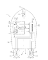
図1は、この発明の一実施形態に係る船舶1の構成を説明するための概念図である。この船舶1は、クルーザやボートのような比較的小型の船舶であり、船体2の船尾(トランサム)3に、一対の船外機11,12が取り付けられている。この一対の船外機11,12は、船体2の船尾3および船首4を通る中心線5に対して、左右対称な位置に取り付けられている。すなわち、一方の船外機11は、船体2の左舷後部に取り付けられており、他方の船外機12は、船体2の右舷後部に取り付けられている。そこで、以下では、これらの船外機を区別するときには、それぞれ、「左舷船外機11」、「右舷船外機12」と呼ぶ。左舷船外機11および右舷船外機12には、それぞれ、電子制御ユニット13,14(以下、「船外機ECU13」、「船外機ECU14」という。)が内蔵されている。
Hereinafter, embodiments of the present invention will be described in detail with reference to the accompanying drawings.
FIG. 1 is a conceptual diagram for explaining the configuration of a
船体2には、操船のための操作卓6が設けられている。操作卓6には、たとえば、舵取り操作のためのステアリング操作部7と、船外機11,12の出力を操作するためのスロットル操作部8と、船体2を一定の旋回角速度(回頭速度。たとえば零)を保持しつつ横移動させるための横移動操作部10(目標合成推進力取得手段、目標移動角度取得手段)とが備えられている。ステアリング操作部7は、操作部材としてのステアリングホイール7aを備える。また、スロットル操作部8は、左舷船外機11および右舷船外機12にそれぞれに対応したスロットルレバー8a,8bを備えている。さらに、横移動操作部10は、この実施形態では、ジョイスティック型の入力装置で構成されており、ほぼ直立した操作レバー10a(目標推進力入力操作部および目標移動角度入力操作部を兼ねる。)と、この操作レバー10aの頭部に回動自在に設けられた回頭速度調整摘み10b(目標角速度入力操作部)とを有している。
The
操作卓6に備えられた上記の操作部7,8,10の操作量は、たとえば、船体2内に配置されたLAN(ローカル・エリア・ネットワーク。以下「船内LAN」という。)を介して、電気信号として航走制御装置20に入力されるようになっている。この航走制御装置20は、マイクロコンピュータを含む電子制御ユニット(ECU)であり、推進力を制御する推進力制御装置としての機能と、舵取り制御のための操舵制御装置としての機能とを有している。この航走制御装置20には、船体2の角速度(ヨーレート。回頭速度)を検出するためのヨーレートセンサ9(角速度検出手段)が出力する角速度信号も、前記船内LANを介して入力されるようになっている。
The amount of operation of the
航走制御装置20は、さらに、船外機ECU13,14との間で前記船内LANを介して通信を行う。より具体的には、航走制御装置20は、船外機ECU13,14から、船外機11,12に備えられたエンジンの回転数(回転速度)NL,NRと、船外機11,12の向きである操舵角φL,φRを取得する。また、航走制御装置20は、船外機ECU13,14に対して、目標操舵角φLt,φRt(添え字「t」は目標値を表す。以下同じ。)、目標スロットル開度、目標シフト位置(前進、ニュートラル、後進)、目標トリム角を表すデータを与えるようになっている。
The
航走制御装置20は、この実施形態では、ステアリング操作部7およびスロットル操作部8の操作に応じて船外機11,12を制御する通常航走モードと、横移動操作部10の操作に応じて船外機11,12を制御する横移動モードとに、制御モードが切り換わるようになっている。具体的には、航走制御装置20は、ステアリング操作部7またはスロットル操作部8からの入力が検出されると通常航走モードとなり、横移動操作部10の操作が検出されると横移動モードとなる。
In this embodiment, the
通常航走モードでは、航走制御装置20は、ステアリングホイール7aの操作に応じて、船外機11,12の操舵角φL,φRを互いに等しい値に制御する。すなわち、船外機11,12は、互いに平行な方向に推進力を発生する。また、通常航走モードにおいて、航走制御装置20は、スロットルレバー8a,8bの操作量および操作方向に応じて、船外機11,12に対する目標スロットル開度および目標シフト位置を定める。スロットルレバー8a,8bは、それぞれ前方および後方へと傾倒させることができるようになっている。操船者がスロットルレバー8aを中立位置から前方へ一定量だけ倒すと、航走制御装置20は、左舷船外機11の目標シフト位置を前進位置とする。操船者がスロットルレバー8aをさらに前方に倒していくと、航走制御装置20は、その操作量に応じて、左舷船外機11の目標スロットル開度を設定する。一方、操船者がスロットルレバー8aを後方に一定量だけ倒すと、航走制御装置20は、左舷船外機11の目標シフト位置を後進位置とする。操船者がスロットルレバー8aをさらに後方に倒していくと、航走制御装置20は、その操作量に応じて、左舷船外機11の目標スロットル開度を設定する。同様に、航走制御装置20は、スロットルレバー8bの操作に応じて、右舷船外機12の目標シフト位置および目標スロットル開度を設定する。
In the normal cruise mode, the
スロットルレバー8a,8bの各頭部は、互いに近接する方向に折り曲げられて、ほぼ水平な把持部を形成している。これにより、操船者は、スロットルレバー8a,8bを両方同時に操作して、左右の船外機11,12のスロットル開度を実質的に等しく保ちながら、船外機11,12の出力を制御できる。
横移動モードでは、航走制御装置20は、横移動操作部10の操作に応じて、左右の船外機11,12の目標操舵角φLt,φRt、目標シフト位置、目標スロットル開度を設定する。この横移動モードによる制御については、後で詳しく述べる。
The head portions of the throttle levers 8a and 8b are bent in directions close to each other to form a substantially horizontal gripping portion. As a result, the operator can control the outputs of the
In the lateral movement mode, the
図2は、船外機11,12の共通の構成を説明するための図解的な断面図である。船外機11,12は、推進機としての推進ユニット30と、この推進ユニット30を船体2に取り付ける取り付け機構31とを有している。取り付け機構31は、船体2の後尾板に着脱自在に固定されるクランプブラケット32と、このクランプブラケット32に水平回動軸としてのチルト軸33を中心に回動自在に結合されたスイベルブラケット34とを備えている。推進ユニット30は、スイベルブラケット34に、操舵軸35まわりに回動自在に取り付けられている。これにより、推進ユニット30を操舵軸35まわりに回動させることによって、操舵角(船体2の中心線に対して推進力の方向がなす方位角)を変化させることができる。また、スイベルブラケット34をチルト軸33をまわりに回動させることによって、推進ユニット30のトリム角(水平面に対して推進力の方向がなす角)を変化させることができる。
FIG. 2 is a schematic sectional view for explaining a common configuration of the
推進ユニット30のハウジングは、トップカウリング36とアッパケース37とロアケース38とで構成されている。トップカウリング36内には、駆動源となるエンジン39がそのクランク軸の軸線が上下方向となるように設置されている。エンジン39のクランク軸下端に連結される動力伝達用のドライブシャフト41は、上下方向にアッパケース37内を通ってロアケース38内にまで延びている。
The housing of the
ロアケース38の下部後側には、推進力発生部材となるプロペラ40が回転自在に装着されている。ロアケース38内には、プロペラ40の回転軸であるプロペラシャフト42が水平方向に通されている。このプロペラシャフト42には、ドライブシャフト41の回転が、クラッチ機構としてのシフト機構43を介して伝達されるようになっている。
シフト機構43は、ドライブシャフト41の下端に固定されたベベルギヤからなる駆動ギヤ43aと、プロペラシャフト42上に回動自在に配置されたベベルギヤからなる前進ギヤ43bと、同じくプロペラシャフト42上に回動自在に配置されたベベルギヤからなる後進ギヤ43cと、前進ギヤ43bおよび後進ギヤ43cの間に配置されたドッグクラッチ43dとを有している。
A
The
前進ギヤ43bは前方側から駆動ギヤ43aに噛合しており、後進ギヤ43cは後方側から駆動ギヤ43aに噛合している。そのため、前進ギヤ43bおよび後進ギヤ43cは互いに反対方向に回転されることになる。
一方、ドッグクラッチ43dは、プロペラシャフト42にスプライン結合されている。すなわち、ドッグクラッチ43dは、プロペラシャフト42に対してその軸方向に摺動自在であるが、プロペラシャフト42に対する相対回動はできず、このプロペラシャフト42とともに回転する。
The
On the other hand, the
ドッグクラッチ43dは、ドライブシャフト41と平行に上下方向に延びるシフトロッド44の軸周りの回動によって、プロペラシャフト42上で摺動される。これにより、ドッグクラッチ43dは、前進ギヤ43bと結合した前進位置と、後進ギヤ43cと結合した後進位置と、前進ギヤ43bおよび後進ギヤ43cのいずれとも結合されないニュートラル位置とのいずれかのシフト位置に制御される。
The dog clutch 43d is slid on the
ドッグクラッチ43dが前進位置にあるとき、前進ギヤ43bの回転がドッグクラッチ43dを介して実質的に滑りのない状態でプロペラシャフト42に伝達される。これにより、プロペラ40は、一方向(前進方向)に回転し、船体2を前進させる方向の推進力を発生する。一方、ドッグクラッチ43dが後進位置にあるとき、後進ギヤ43cの回転がドッグクラッチ43dを介して実質的に滑りのない状態でプロペラシャフト42に伝達される。後進ギヤ43cは、前進ギヤ43bとは反対方向に回転するため、プロペラ40は、反対方向(後進方向)に回転し、船体2を後進させる方向の推進力を発生する。ドッグクラッチ43dがニュートラル位置にあるとき、ドライブシャフト41の回転はプロペラシャフト42に伝達されない。すなわち、エンジン39とプロペラ40との間の駆動力伝達経路が遮断されるので、いずれの方向の推進力も生じない。
When the dog clutch 43d is in the forward position, the rotation of the
エンジン39に関連して、このエンジン39を始動させるためのスタータモータ45が配置されている。スタータモータ45は、船外機ECU13,14によって制御される。また、エンジン39のスロットルバルブ46を作動させてスロットル開度を変化させ、エンジン39の吸入空気量を変化させるためのスロットルアクチュエータ51が備えられている。このスロットルアクチュエータ51は、電動モータからなっていてもよい。このスロットルアクチュエータ51の動作は、船外機ECU13,14によって制御される。エンジン39には、さらに、クランク軸の回転を検出することによってエンジン39の回転数NL,NRを検出するためのエンジン回転検出部48が備えられている。
In relation to the
また、シフトロッド44に関連して、ドッグクラッチ43dのシフト位置を変化させるためのシフトアクチュエータ52(クラッチ作動装置)が設けられている。このシフトアクチュエータ52は、たとえば、電動モータからなり、船外機ECU13,14によって動作制御される。
さらに、推進ユニット30に固定された操舵ロッド47には、たとえば、液圧シリンダを含み、船外機ECU13,14によって制御される操舵アクチュエータ53が結合されている。この操舵アクチュエータ53を駆動することによって、推進ユニット30を操舵軸35まわりに回動させることができ、舵取り操作を行うことができる。このように、操舵アクチュエータ53、操舵ロッド47および操舵軸35を含む舵取り機構50が形成されている。この舵取り機構50には、操舵角φL,φRを検出するための操舵角センサ49が備えられている。
Further, a shift actuator 52 (clutch actuating device) for changing the shift position of the dog clutch 43d is provided in association with the
Further, the steering
また、クランプブラケット32とスイベルブラケット34との間には、たとえば液圧シリンダを含み、船外機ECU13,14によって制御されるトリムアクチュエータ(チルトトリムアクチュエータ)54が設けられている。このトリムアクチュエータ54は、チルト軸33まわりにスイベルブラケット34を回動させることにより、推進ユニット30をチルト軸33まわりに回動させる。これにより、推進ユニット30のトリム角が変化する。
A trim actuator (tilt trim actuator) 54 including a hydraulic cylinder and controlled by the
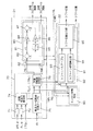
図3は、前記船舶1の航走制御に関する構成(操船支援システム)を示すブロック図である。航走制御装置20は、左右の船外機11,12のスロットルアクチュエータ51の制御のための目標スロットル開度指令値を発生するスロットル制御部21と、船外機11,12のシフトアクチュエータ52の制御のための目標シフト位置指令値を発生するシフト制御部22(クラッチ制御手段)と、船外機11,12の操舵アクチュエータ53の制御のための目標操舵角φLt,φRtを生成する操舵制御部23と、船外機11,12のトリムアクチュエータ54の制御のための目標トリム角指令値を生成するトリム角制御部24とを備えている。これらの制御部21〜24の機能は、航走制御装置20に備えられたマイクロコンピュータが所定のソフトウェア処理を実行することによって実現されるようになっていてもよい。
FIG. 3 is a block diagram showing a configuration (a ship maneuvering support system) related to the cruise control of the
制御部21〜24が生成する各指令値は、インタフェース部(I/F)25を介して、船外機ECU13,14に与えられる。船外機ECU13,14は、与えられた指令信号に基づいて、アクチュエータ51〜54を制御する。
船外機ECU13,14は、エンジン回転検出部48によって検出されるエンジン回転数NL,NRと、操舵角センサ49によって検出される操舵角φL,φRとを、インタフェース部25を介して、航走制御装置20に与える。エンジン回転数NL,NRは、スロットル制御部21に与えられ、操舵角φL,φRは、操舵制御部23に与えられる。この操舵角φL,φRは、操舵制御部23からスロットル制御部21にも与えられるようになっていてもよい。操舵角φL,φRの代わりに、目標操舵角φLt,φRtを、操舵制御部23からスロットル制御部21に与えるようにしてもよい。
The command values generated by the
The
一方、航走制御装置20には、ステアリング操作部7、スロットル操作部8、ヨーレートセンサ9および横移動操作部10からの信号が、インタフェース部(I/F)26を介して入力されるようになっている。ステアリング操作部7からの入力信号は、目標操舵角φLt,φLtを算出するために操舵制御部23に入力される。また、スロットル操作部8からの入力信号は、目標推進力の大きさを表す信号がスロットル制御部21に入力されるほか、推進力の方向を表す信号がシフト制御部22に入力されるようになっている。ヨーレートセンサ9が検出する角速度ωは、操舵制御部23に入力される。
On the other hand, signals from the
横移動操作部10からの信号は、目標合成推進力および目標移動角度(方位)を表す信号としてスロットル制御部21に入力されるほか、回頭速度調整摘み10bの操作によって設定された目標角速度ωtは、操舵制御部23に入力されるようになっている。
シフト制御部22には、スロットル制御部21からの間欠シフト指令信号も与えられるようになっている。間欠シフト指令信号は、目標推進力に対応するエンジン回転数がエンジン39のアイドル回転数(下限回転数。たとえば、700rpm)よりも低い場合に、ドッグクラッチ43dを前進位置または後進位置とニュートラル位置との間で交互に切り換える間欠シフト動作を行わせるための信号である。この間欠シフト動作により、アイドル回転数よりも低いエンジン回転数に対応した推進力の発生が可能になる。この動作の詳細については後述する。
The signal from the lateral
The
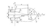
図4は、横移動モードにより船舶1を航走させる場合の原理について説明するための図である。船体2の中心線5が船尾3と交わる位置を原点Oとし、中心線5に沿って船首4側にx軸をとり、原点Oから船尾3(トランサム)に沿って左舷側に向かってy軸をとる。原点Oは、船外機11,12に備えられた一対の推進ユニット30による推進力発生点の中間点である。
FIG. 4 is a diagram for explaining the principle when the
横移動モードにおいて、操舵制御部23は、左右の船外機11,12が発生する推進力ベクトルTL,TRの延長線である作用線(破線で示す。)がx軸上の所定範囲内で交わり、かつ、目標角速度ωtが達成されるように、左右の船外機11,12の目標操舵角φLt,φRtを設定する。このとき、トリム角制御部24は、船外機11,12の推進ユニット30が発生する推進力の水平方向成分を揃えるために、左右の船外機11,12のトリム角を互いに等しい値に制御する。
In the lateral movement mode, the
推進力ベクトルTL,TRの作用線の交点を作用点F=(a,0)(ただし、a>0)と表し、左右の船外機11,12が中心線5に対して対称な位置(0,b),(0,−b)(ただし、bは定数であり、b>0。)でそれぞれ推進力を発生するものとする。この場合、右舷船外機12の操舵角φR=φとすると、左舷船外機11の操舵角φLは、φL=−φと表される。φ=tan-1(b/a)である。
The intersection of the action lines of the propulsive force vectors TL and TR is expressed as an action point F = (a, 0) (where a> 0), and the left and right
作用点Fにおいて推進力ベクトルTL,TRを合成した合成ベクトルをTGで表す。この合成ベクトルTGの方向(x軸に対して移動角度θをなす方向)は、合成された推進力の方向(船体2の移動方向)を表し、合成ベクトルTGの大きさは合成された推進力の大きさを表す。したがって、横移動操作部10から与えられる船体2の目標移動角度θt(操作レバー10aの傾倒方向に対応)に合成ベクトルTGの方向を合致させ、かつ、横移動操作部10から与えられる目標合成推進力(操作レバー10aの傾倒量に対応)に合成ベクトルTGの大きさ|TG|を合致させればよい。換言すれば、このような合成ベクトルTGが得られるように、左右の船外機11,12の目標推進力ベクトルTLt,TRtを定めればよい。
A combined vector obtained by combining the propulsive force vectors TL and TR at the action point F is represented by TG. The direction of the combined vector TG (the direction that forms the movement angle θ with respect to the x-axis) represents the direction of the combined propulsive force (the moving direction of the hull 2), and the magnitude of the combined vector TG is the combined propulsive force. Represents the size of. Therefore, the direction of the composite vector TG is made to coincide with the target movement angle θ t of the hull 2 (corresponding to the tilting direction of the
作用点Fが船体2の瞬間中心Gと一致する場合が最も簡単な場合である。このとき、船体2の角速度ω(瞬間中心Gまわりの角速度)は零となり、船首4の方位を一定に保持しつつ、船体2を横方向移動(平行移動)させることができる。
より具体的には、図5に示すように、作用点Fが瞬間中心Gに一致するように操舵角φR=φ、φL=−φ(ただし、φ≧0)と定めるとともに、左舷船外機11からは後進方向への推進力を発生させ、右舷船外機12からは前進方向への推進力を発生させて、|TL|=|TR|とする。このとき、船体2は船首4の方位を一定に保持したままで、船首4の方向に対して垂直に左側へ平行移動する。このような真横移動動作により、船舶1の着岸または離岸操作を行うことができる。
The case where the action point F coincides with the instantaneous center G of the
More specifically, as shown in FIG. 5, the steering angles φR = φ and φL = −φ (where φ ≧ 0) are determined so that the action point F coincides with the instantaneous center G, and the port side outboard motor is set. 11 generates a propulsive force in the reverse direction, and generates a propulsive force in the forward direction from the starboard
作用点Fが瞬間中心Gと不一致のとき(図4参照)、瞬間中心Gまわりの回転モーメントが発生し、船体2の角速度ωが零に等しくなくなる。換言すれば、横移動操作部10の回頭速度調整摘み10bによって、零以外の目標角速度ωtが設定されたときには、この目標角速度ωtに応じて、瞬間中心Gと作用点Fとにずれが生じるように、操舵角φL,φRが制御される。
When the action point F does not coincide with the instantaneous center G (see FIG. 4), a rotational moment around the instantaneous center G is generated, and the angular velocity ω of the
実際には、この実施形態では、ヨーレートセンサ9によって検出される角速度ωが、目標角速度ωtに等しくなるように、操舵角φL,φRが制御される。この場合に、角速度ω=0のとき、瞬間中心Gが中心線5上にあれば、作用点Fが瞬間中心Gと一致することになる。角速度ω≠0のときには、瞬間中心Gが中心線5上にあっても、作用点Fと瞬間中心Gとは一致しない。
In fact, in this embodiment, the angular velocity omega is detected by the
図6は、操舵角φL,φRのより具体的な制御を説明するための図解図である。瞬間中心Gは、中心線5上にあるとは限らない。たとえば、小型の船舶1では、船体2上で乗員が移動したり、船体2に装備した水槽に、水揚げした魚を積載していったりすることにより、瞬間中心Gは容易に移動し、その位置は中心線5上に制限されるわけではない。
しかし、瞬間中心Gが中心線5上にない場合であっても、中心線5上に作用点Fを位置させつつ、所望の横移動操船が可能である。具体的には、瞬間中心Gを通り、目標移動角度θtの方向に沿う直線60を引いたときに、この直線60と中心線5との交点に作用点Fを位置させる。そして、この作用点Fから、直線60に沿う合成推進力ベクトルTGが得られるように、左右の船外機11,12の推進力ベクトルTL,TRの大きさを定めればよい。これにより、角速度ω=0に保持しつつ、船体2を平行移動させることができる。
FIG. 6 is an illustrative view for explaining more specific control of the steering angles φL and φR. The instantaneous center G is not necessarily on the
However, even when the instantaneous center G is not on the
左右の船外機11,12の推進ユニット30は、操舵軸35まわりの制限角度範囲内での回動させることができるに過ぎない。そのため、作用点Fは、実際には、中心線5上で所定の下限値(amin,0)よりも原点Oの近くに位置させることはできない。また、中心線5上で所定の上限値(amax,0)よりも遠くに作用点Fを位置させ、かつ、横方向への所望の合成ベクトルTGを得ようとすると、左右の船外機11,12から、極めて大きな推進力を発生させなければならない。したがって、中心線5上における作用点Fの位置は、操舵角による制限およびエンジン39の出力による制限のために、(amin,0)と(amax,0)の範囲Δx内に制限される。
The
この制限のために、作用点Fを中心線5上に配置する限り、たとえば、瞬間中心Gが図6に示す位置(a′,c)にあるとき、この瞬間中心Gから図6において斜線を付して示す範囲へと向かう平行移動を実現することができない。つまり、角速度ω=0を実現することができず、船体2に回転モーメントが与えられてしまう。
そこで、この実施形態では、図7に示すように、操舵角φRを減少させていって、所定の切換え基準舵角φSに達したときには、中心線5外に作用点Fを設定する。所定の切換え基準舵角φSに達したときとは、作用点Fが(amax,0)に達しても角速度ω=ωt(たとえばωt=0)とすることができない場合である。この場合、角速度ω=0となるように操舵角φL,φRを制御すると、瞬間中心Gを通り、目標移動角度θに沿う直線62上に作用点Fが位置することになる。そして、所望の大きさおよび方向の合成ベクトルTGが得られるように、左右の船外機11,12の出力(推進力)が制御される。
Because of this limitation, as long as the action point F is arranged on the
Therefore, in this embodiment, as shown in FIG. 7, when the steering angle φR is decreased and the predetermined switching reference steering angle φ S is reached, the action point F is set outside the
一般には、瞬間中心Gは、船体2内のいずれかの位置にあるから、船体2の左右方向の幅程度の所定範囲Δy内で作用点を定められれば十分である。この所定範囲Δy内に作用点Fを定めても目標角速度ωtを達成できないときには、たとえば、アラームを発生して、操船者にそのことを報知するようにしてもよい。
操舵角φRを大きくしていって、作用点Fが中心線5上で(amin,0)に達してもなお目標角速度ωtを達成できないときも同様に、アラームを発生して、操船者にそのことを報知することが好ましい。
In general, since the instantaneous center G is located at any position in the
Go to increase the steering angle φR, as well when you can not be achieved on the
制御を簡単にするために、図7に示された状況のとき、左右の船外機11,12の操舵角φL,φRは、次の式によって算出される。
φL=ψ−φS
φR=ψ+φS (ψは操舵角補正値)
このように操舵角φL,φRを定めることとしておけば、目標角速度ωtを達成できる操舵角補正値ψを定めればよいことになるから、制御演算が簡単になる。ただし、φSは、作用点Fが中心線5上の点(amax,0)にあるときの操舵角である切換え基準舵角であり、φS=tan-1(b/amax)である。
In order to simplify the control, the steering angles φL and φR of the left and right
φL = ψ−φ S
φR = ψ + φ S (ψ is the steering angle correction value)
Thus the steering angle .phi.L, if as a to define a .phi.R, since so that may be set a steering angle correction value that can achieve the target angular speed omega t [psi, the control operation is simplified. However, φ S is a switching reference rudder angle that is a steering angle when the action point F is at the point (a max , 0) on the
次に、図4を参照して、左右の船外機11,12から発生させるべき推進力|TL|,|TR|の具体的な算出方法について説明する。
横移動操作部10から入力される目標合成推進力TGtの大きさ|TGt|は、船舶1全体の質量および生じさせたい加速度によって定まる。この目標合成推進力の大きさ|TGt|を実現する右舷船外機12の目標推進力ベクトルTRtの大きさ|TRt|が、左舷船外機11の目標推進力ベクトルTLtの大きさ|TLt|にスカラー量である下記第(1)式の係数kを乗じることによって与えられるものとする(下記第(1)式)。
Next, a specific method for calculating the propulsive forces | TL | and | TR | to be generated from the left and right
The magnitude | TG t | of the target composite propulsive force TG t input from the lateral
|TLt|=k|TRt| ……(1)
ただし、横移動モードにおいて、φt=φRt=−φLt(φtは目標操舵角基本値)となるように、左右の船外機11,12の目標操舵角φRt,φLtが設定されるものとする。
一方、左右の船外機11,12の目標推進力ベクトルTLt,TRtを合成することによって、目標合成推進力ベクトルTGtが得られる場合に、目標合成推進力ベクトルTGtのx方向成分TGtxおよびy方向成分TGtyについて、次式が成り立つ。
| TL t | = k | TR t | (1)
However, the transverse movement mode, φ t = φR t = -φL t (φ t is the target steering angle basic value) so that the target steering angle .phi.R t of the right and left
On the other hand, the target propulsive force vectors TL t of the right and left
TGtx=|TGt|cosθt=|TRt|cosφt+|TLt|cosφt ……(2)
TGty=|TGt|sinθt=|TRt|sinφt−|TLt|sinφt ……(3)
これより、|TRt|は次式で表すことができる。
TG t x = | TG t | cos θ t = | TR t | cos φ t + | TL t | cos φ t (2)
TG t y = | TG t | sin θ t = | TR t | sin φ t − | TL t | sin φ t (3)
From this, | TR t | can be expressed by the following equation.

一方、上記第(2)式および第(3)式から、次の関係が得られる。 On the other hand, the following relationship is obtained from the equations (2) and (3).
この第(5)式に前記第(1)式を代入して整理すると、次式が得られる。 Substituting the formula (1) into the formula (5) and rearranging the formula gives the following formula.
これをkについて解くことにより、次式が得られる。
k=(tanφt−tanθt)/(tanφt+tanθt) ……(7)
したがって、目標操舵角基本値φt(=φRt)および目標移動角度θtから、前記第(7)式によって係数kが得られ、この係数k、目標操舵角基本値φt、目標移動角度θtおよび目標合成推進力|TGt|に基づいて、前記第(4)式によって、右舷船外機12の目標推進力|TRt|が得られる。さらに、前記第(1)式により、左舷船外機12の目標推進力|TLt|が求まる。
Solving this for k yields:
k = (tanφ t -tanθ t) / (tanφ t + tanθ t) ...... (7)
Therefore, a coefficient k is obtained from the target steering angle basic value φ t (= φR t ) and the target movement angle θ t by the above equation (7). This coefficient k, the target steering angle basic value φ t , the target movement angle Based on θ t and the target composite propulsive force | TG t |, the target propulsive force | TR t | of the starboard
そこで、目標操舵角基本値φt(右舷船外機12の操舵角センサ49による検出値でもよい。)、目標移動角度θtおよび目標合成推進力|TGt|を入力として、マイクロコンピュータによる演算処理によって、左右の船外機11,12の目標推進力|TLt|,|TRt|を求めることができる。
ただし、前記第(4)式は、θt=−π/4,3π/4(rad)のときに0/0となって計算できなくなる。そこで、後述の実施形態では、0から2πまでの範囲でπ/36刻みの目標移動角度θtについて、様々な目標操舵角基本値φtおよび目標合成推進力|TGt|に対する前記目標推進力|TLt|,|TRt|が予め算出され、その算出結果をマップとして保持して、推進力の制御に用いるようにしている。
Therefore, the microcomputer calculates using the target steering angle basic value φ t (which may be detected by the
However, the equation (4) becomes 0/0 when θ t = −π / 4, 3π / 4 (rad) and cannot be calculated. Therefore, in the embodiment described later, the target propulsive force with respect to various target steering angle basic values φ t and target composite propulsive force | TG t | with respect to the target moving angle θ t in increments of π / 36 in the range from 0 to 2π. | TL t | and | TR t | are calculated in advance, and the calculation results are held as a map and used for propulsion control.
図7のように、作用点Fが中心線5からずれると、φL=−φR=−φなる関係が崩れる。しかし、この場合でも、前記マップの適用が可能である。これは、φLt=ψt−φS,φRt=ψt+φSとして操舵角目標値φLt,φRtが定められるからである。より具体的には、目標操舵角基本値φtを操舵角入力値φRt−ψt(または、φt←φR−ψt)に置き換え、かつ、目標移動角度θtを目標移動角度入力値θt−ψtに置き換えて、前記マップを適用すればよい。
As shown in FIG. 7, when the action point F deviates from the
図8は、スロットル制御部21およびシフト制御部22の機能的な構成を説明するためのブロック図であり、とくに、横移動モードのときの制御に関する構成が示されている。スロットル制御部21は、左右の船外機11,12のエンジン39の目標エンジン回転数|NLt|および|NRt|を算出する目標エンジン回転数算出モジュール70(目標推進力算出手段)と、算出された目標エンジン回転数|NLt|および|NRt|に基づいて船外機11,12のエンジン39の各目標スロットル開度を算出するスロットル開度算出モジュール80(推進力制御手段)とを備えている。
FIG. 8 is a block diagram for explaining functional configurations of the
目標エンジン回転数算出モジュール70は、操舵制御部23から右舷船外機12の操舵角φR(目標操舵角φRtでもよい。)および前記目標操舵角補正値ψtを得て、マップ検索用の操舵角入力値φR−ψt(またはφRt−ψt)を算出する操舵角入力値算出部71と、横移動操作部10からの目標移動角度θtと前記目標操舵角補正値ψtとに基づいてマップ検索用の目標移動角度入力値θt−ψtを算出する目標移動角度入力値算出部72とを備えている。さらに、目標エンジン回転数算出モジュール70は、左舷船外機11の目標推進力|TLt|,|TRt|を算出する目標推進力算出部74と、この目標推進力|TLt|,|TRt|に対応する左右の船外機11,12の目標エンジン回転数NLt、NRt(推進力の発生方向を表す符号付きの値)を生成する推進力−回転数変換テーブル75と、目標エンジン回転数の絶対値|NLt|,|NRt|を求め、これらを所定の下限回転数(たとえば、エンジン39のアイドル回転数に等しい。)と比較する下限回転数判定部76とを備えている。
The target engine
目標推進力算出部74は、操舵角入力値φR−ψt(またはφRt−ψt)、目標移動角度入力値θt−ψtおよび横移動操作部10から与えられる目標合成推進力|TGt|を入力として、前記目標推進力|TLt|,|TRt|を出力する前述のマップからなる。
目標推進力|TLt|,|TRt|は、そのままでは、エンジン39の制御に適さないので、エンジン39の特性に従って、推進力−回転数変換テーブル75において、目標エンジン回転数NLt,NRtに変換される。目標エンジン回転数NLt,NRtの符号は、目標移動角度θtに応じて定められる。具体的には、0≦θt≦πであれば、左舷船外機11の目標回転速度NLtには後進を表す負符号が付与され、右舷船外機12の目標回転速度NRtには前進を表す正符号が付与される。一方、π<θt<2π(または−π<θt<0)であれば、左舷船外機11の目標回転速度NLtには前進を表す正符号が付与され、右舷船外機12の目標回転速度NRtには後進を表す負符号が付与される。求められた目標エンジン回転数NLt,NRtは、回転速度比較手段としての下限回転数判定部76に与えられるほか、シフト制御部22にも入力される。
The target propulsive
Since the target propulsive force | TL t |, | TR t | is not suitable for the control of the
下限回転数判定部76は、目標エンジン回転数の絶対値|NLt|,|NRt|が下限回転数NLL(=アイドル回転数)未満かどうかを判定し、その判定結果をシフト制御部22に与える。また、目標エンジン回転数の絶対値|NLt|,|NRt|は、スロットル開度算出モジュール80に与えられる。ただし、左舷船外機11の目標エンジン回転数|NLt|が下限回転数NLL未満である場合は、下限回転数判定部76は、目標エンジン回転数|NLt|に下限回転数NLLを代入する。同様に、右舷船外機12の目標エンジン回転数|NRt|が下限回転数NLL未満である場合には、下限回転数判定部76は、目標エンジン回転数|NRt|に下限回転数NLLを代入する。
The lower limit rotational
スロットル開度算出モジュール80は、左舷PI(比例積分)制御モジュール81と、右舷PI制御モジュール82とを有し、これらは同じ構成を有している。左舷PI制御モジュール81には、下限回転数判定部76から左舷船外機11の目標エンジン回転数|NLt|が入力されるとともに、左舷船外機11の船外機ECU13から現在のエンジン回転数NL(≧0)が入力されるようになっている。これらの偏差εL=|NLt|−NLが偏差演算部83によって算出される。偏差演算部83が出力する偏差εLは、比例ゲイン乗算部84に与えられるとともに、積分部85において離散積分処理を受ける。この積分部85による積分結果は、積分ゲイン乗算部86に与えられる。比例ゲイン乗算部84は、偏差εLに対して比例ゲインkpを乗じた値を出力し、積分ゲイン乗算部86は偏差εLの積分値に積分ゲインkiを乗じた値を出力する。これらが、加算部87によって加算されることにより、左舷船外機11のエンジン39に対する目標スロットル開度が得られる。この目標スロットル開度は、左舷船外機11の船外機ECU13に与えられる。このように、左舷PI制御モジュール81は、いわゆるPI(比例積分)制御を実行する。
The throttle
右舷PI制御モジュール82も同様に構成されている。すなわち、右舷PI制御モジュール82は、右舷船外機12のための目標エンジン回転数|NRt|と現在のエンジン回転数NR(≧0)との偏差εRに対してPI(比例積分)制御を実行して、右舷船外機12のエンジン39に対する目標スロットル開度を出力する。この目標スロットル開度は、右舷船外機12の船外機ECU14に与えられる。
The starboard
シフト制御部22は、左舷シフト制御モジュール91と、右舷シフト制御モジュール92とを有し、これらは同様に構成されている。これらのシフト制御モジュール91,92は、推進力−回転数変換テーブル75から与えられる目標エンジン回転数NLt,NRtに基づいて船外機11,12のシフト機構43(より具体的にはドッグクラッチ43d)のシフト位置を、前進位置、後進位置またはニュートラル位置に制御するためのシフト制御信号をそれぞれ生成するものである。これらのシフト制御モジュール91,92は、目標エンジン回転数NLt,NRtが下限回転数NLL未満のときには、シフト機構43のシフト位置をニュートラル位置と前進位置または後進位置とに交互に周期的に切り換え、エンジン39とプロペラ40との間を間欠的に結合する間欠シフト制御(間欠結合制御)を実行する。
The
以下、この間欠シフト制御を「PWM制御」(パルス幅変調制御)という。また、PWM制御の周期S中において、シフト位置が前進位置または後進位置とされることによって、エンジン39の回転がプロペラシャフト42に伝達される時間を「シフトイン時間」という。PWM周期S中において、シフトイン時間Sinを除く時間(S−Sin)は、シフト位置がニュートラル位置とされる「ニュートラル時間」である。
Hereinafter, this intermittent shift control is referred to as “PWM control” (pulse width modulation control). Further, the time during which the rotation of the
左舷シフト制御モジュール91は、推進力−回転数変換テーブル75から与えられる左舷船外機11の目標エンジン回転数NLtの符号に基づいてシフト機構43のシフト位置(前進位置、後進位置またはニュートラル位置)を出力するシフトルールテーブル93を備えている。また、左舷シフト制御モジュール91は、推進力−回転数変換テーブル75から与えられる目標エンジン回転数NLtの絶対値|NLt|に基づいてシフトイン時間Sinを算出するシフトイン時間算出部94(結合維持時間算出手段)を備えている。さらに、左舷シフト制御モジュール91は、シフトルールテーブル93およびシフトイン時間算出部94の出力に基づいて、左舷船外機11のシフト機構43のシフト位置信号を生成するシフト位置出力部95(間欠結合制御手段)を備えている。
The port
シフトルールテーブル93は、目標エンジン回転数NLtの符号が正のとき、前進位置を表す信号を出力し、その符号が負のとき後進位置を表す信号を出力する。また、目標エンジン回転数NLtの絶対値が、実質的に零とみなすことができる場合(たとえば、100rpm以下)のときに、ニュートラル位置を表す信号を出力する。
シフトイン時間算出部94は、下限回転数判定部76が、目標エンジン回転数NLtが下限回転数NLL以上であると判定していれば、Sin=Sとする。この場合、PWM制御は行われず、シフト機構43のシフト位置は、シフトルールテーブル93が生成したシフト位置に保持される。一方、下限回転数判定部76が、目標エンジン回転数NLtが下限回転数NLL未満であると判定している場合には、シフトイン時間算出部94は、PWM制御のデューティ比DをD=NLt/NLLとし、シフトイン時間Sin=S・Dに設定する。
The shift rule table 93 outputs a signal representing the forward position when the sign of the target engine speed NL t is positive, and outputs a signal representing the reverse position when the sign is negative. Further, when the absolute value of the target engine speed NL t can be regarded as substantially zero (for example, 100 rpm or less), a signal representing the neutral position is output.
The shift-in
シフト位置出力部95は、PWM周期Sを周期としてシフト位置信号を出力する。より具体的には、シフト位置出力部95は、PWM周期S中において、シフトイン時間算出部94が算出したシフトイン時間Sinに渡って、シフトルールテーブル93の出力に従うシフト位置信号を継続して生成し、残余のニートラル時間には、シフトルールテーブル93の出力によらずに、ニートラル位置を表すシフト位置信号を生成する。むろん、シフトイン時間Sin=Sであれば、終始、シフトルールテーブル93の出力に従うシフト位置信号が出力されることになる。
The shift
右舷シフト制御モジュール92も同様に構成されていて、右舷船外機12に対応した目標エンジン回転数NRt、およびその絶対値に対する下限回転数判定部76の判定結果に対して、同様の動作を実行して、右舷船外機12のシフト機構43のシフト位置を制御する。
船外機11,12のエンジン39は、その性質上、下限回転数NLL未満で作動させることはできないから、下限回転数NLL未満の出力は得られない。そこで、この実施形態では、下限回転数NLL未満の絶対値を有する目標エンジン回転数NLt,NRtが設定されたときには、エンジン39を下限回転数NLLで作動させる一方で、エンジン39の回転が、目標エンジン回転数NLt,NRtに応じたデューティ比Dで間欠的にプロペラ40に伝達される。これにより、アイドル回転数NLL未満の回転数に相当する推進力を得ることができるようになっている。
The starboard
Since the
シフト制御部22には、さらに、横移動モード中に、左右の船外機11,12のエンジン39が停止しているかどうかを判定するためのエンジン状態判定部90(原動機状態判定手段)が備えられている。このエンジン状態判定部90は、船外機ECU13,14から、左右の船外機11,12のエンジン39の回転数NL,NRを取得する。そして、エンジン状態判定部90は、エンジン回転数NL,NRが実質的に零かどうかに基づき、エンジン39が動作中かどうかを判定する。もしも、横移動モード中にいずれかの船外機のエンジン39が停止状態となると、このことを表す信号がシフト位置出力部95に与えられる。これに応答して、シフト位置出力部95は、全ての船外機11,12のシフト機構43のシフト位置をニュートラルに制御する。
The
また、エンジン状態判定部90は、エンジン39の再始動を制御する再始動制御手段としての機能も有している。すなわち、エンジン状態判定部90は、横移動モード中にいずれかの船外機11,12のエンジン39が停止状態に陥ったと判断すると、当該船外機11,12の船外機ECU13,14に対して、エンジン39の再始動を要求する。これに応答して、船外機ECU13,14は、スタータモータ45を作動させる。
The engine
エンジン状態判定部90は、エンジン回転数NL,NRを監視して、エンジン39が再始動したかどうかを判断する。停止状態のエンジン39が再始動して、全ての船外機11,12のエンジン39が動作状態となると、そのことを表す信号がシフト位置出力部95に与えられる。これに応答してシフト位置出力部95は、シフトルールテーブル93およびシフトイン時間算出部94の出力に応じて、シフト機構43を制御する状態に復帰する。
The engine
図9は、左舷シフト制御モジュール91および右舷シフト制御モジュール92によるPWM動作を説明するためのタイミングチャートである。実線は、左舷シフト制御モジュール91によって制御される左舷船外機11のシフト機構43のシフト位置の変化を表す。破線は、右舷シフト制御モジュール92によって制御される右舷船外機12のシフト機構43のシフト位置の変化を表す。
FIG. 9 is a timing chart for explaining the PWM operation by the starboard
左右の船外機11,12の目標エンジン回転数NLt,NRtの絶対値がいずれも下限回転数(アイドル回転数)NLL未満の場合を想定する。このとき、左舷シフト制御モジュール91および右舷シフト制御モジュール92にそれぞれ備えられたシフトイン時間算出部94は、それぞれシフトイン時間Sin_L,Sin_Rを算出する。したがって、左舷船外機11では、PWM周期S中のシフトイン時間Sin_Lに渡って、ドッグクラッチ43dが前進位置または後進位置にシフトインし、残余の時間(S−Sin_L)には、ドッグクラッチ43dはニュートラル位置となる。同様に、右舷船外機12では、PWM周期S中のシフトイン時間Sin_Rに渡って、ドッグクラッチ43dが前進位置または後進位置にシフトインし、残余の時間(S−Sin_R)には、ドッグクラッチ43dはニュートラル位置となる。シフトイン時間Sin_L,Sin_R中には、下限回転数NLLで回転しているエンジン39の回転がプロペラ40に伝達される。
Assume that the absolute values of the target engine speeds NL t and NR t of the left and right
この実施形態では、左舷シフト制御モジュール91および右舷シフト制御モジュール92にそれぞれ備えられたシフト位置出力部95は、PWMシフト制御を互いに同期させる。すなわち、図9に示されているように、各PWM周期において、シフトインタイミングを同期させるようになっている。これにより、PWM制御時における乗り心地を改善できる。むろん、PWMシフト制御を同期させなくとも、各船外機11,12から必要な推進力を発生させることができるが、左右の船外機11,12におけるシフトインタイミングのずれに起因して、乗り心地が悪くなる。
In this embodiment, the shift
図10は、操舵制御部23の機能的な構成を示すブロック図であり、とくに、横移動モードのときの制御に関する構成が示されている。操舵制御部23は、作用点Fが中心線5上にあるときの目標操舵角φRt,φLtを演算する第1目標操舵角演算部101(目標操舵角算出手段)と、作用点Fが中心線5外にあるときの目標操舵角φRt,φLtを演算するための第2目標操舵角演算部102(目標操舵角算出手段)と、これらの出力のいずれかを選択して出力するセレクタ103と、このセレクタ103の切り換えを制御するための比較部104とを備えている。
FIG. 10 is a block diagram showing a functional configuration of the
比較部104は、第1目標操舵角演算部101が演算する右舷船外機12の目標操舵角φRtと、前記切換え基準舵角φS(=tan-1(b/amax))とを比較する。すなわち、比較部104は、第1目標操舵角演算部101が演算する右舷船外機12の目標操舵角φRtが切換え基準舵角φS以上であれば、セレクタ103に、第1目標操舵角演算部101の出力を選択させる。一方、第1目標操舵角演算部101が演算する右舷船外機12の目標操舵角φRtが切換え基準舵角φS未満であるときは、比較部104は、セレクタ103に、第2目標操舵角演算部102の出力を選択させる。
The
第1目標操舵角演算部101は、ヨーレートセンサ9によって検出される角速度ωと、横移動操作部10から与えられる目標角速度ωtとを入力としたPI(比例積分)制御モジュールで構成されている。すなわち、第1目標操舵角演算部101は、PI制御によって、角速度ωを目標角速度ωtに一致させるように動作する。より具体的には、第1目標操舵角演算部101は、角速度ωと目標角速度ωtとの偏差εωを演算する偏差演算部106と、この偏差演算部106の出力εωに対して比例ゲインkω1を乗じる比例ゲイン乗算部107と、偏差演算部106が出力する偏差εωを積分する積分部108と、この積分部108の出力に対して積分ゲインkθ1を乗じる積分ゲイン乗算部109と、比例ゲイン乗算部107および積分ゲイン乗算部109の出力を加算して操舵角偏差Δφを生成する第1加算部110とを備えている。これらが、操舵角偏差演算手段を構成している。
The first target steering
さらに、第1目標操舵角演算部101は、基本目標操舵角としての初期目標操舵角φiを記憶するメモリ111(基本目標操舵角記憶手段)と、このメモリ111に記憶された初期目標操舵角φiを前記第1加算部110が生成する操舵角偏差Δφに加算して目標操舵角基本値φt(=φi+Δφ)を求める第2加算部112(加算手段)とを備えている。この目標操舵角基本値φtは、そのまま右舷船外機12のための目標操舵角φRtとして用いられる。また、目標操舵角基本値φtの符号を反転部113で反転した値−φtが左舷船外機11のための目標操舵角φLtとされる。
Further, the first target steering
メモリ111は、不発性の書き換え可能なメモリ、たとえばフラッシュメモリやEEPROM(電気的に消去・書き込み可能な読出し専用メモリ)で構成されている。このメモリ111には、たとえば、ディラーからユーザーへの船舶1の受け渡しに先だって、たとえば、専用の入力装置を用いて、初期目標操舵角φiが書き込まれている。このときの初期目標操舵角φiは、たとえば、船体2および船外機11,12の種類に応じて定まる設計上の瞬間中心Gi(ai,0)に基づいて、φi=tan-1(b/ai)とされる。瞬間中心Gi(ai,0)は、テスト航走を行って実測により求めることとしてもよい。
The
メモリ111には、初期目標操舵角φiに対応するパラメータai,bを初期目標操舵角情報として格納することとしてもよい。この場合、初期目標操舵角φiは、φi=tan-1(b/ai)の演算によって求められることになる。
この実施形態では、船舶1の荷重の変化等に依存する瞬間中心Gの変動を学習する学習機能が付加されている。すなわち、メモリ111における初期目標操舵角φiを更新する書込み処理部114が設けられている。この書込み処理部114は、船外機11,12を駆動停止して航走制御を停止するときや、横移動モードから通常航走モードに切り換わるときに、第2加算部112が生成している目標操舵角基本値φtを、新たな初期目標操舵角φiとしてメモリ111に書き込む。
The
In this embodiment, a learning function for learning the fluctuation of the instantaneous center G depending on the load change of the
第2目標操舵角演算部102も、ヨーレートセンサ9によって検出される角速度ωと、横移動操作部10から与えられる目標角速度ωtとを入力としたPI(比例積分)制御モジュールで構成されている。すなわち、第2目標操舵角演算部102は、PI制御によって、角速度ωを目標角速度ωtに一致させるように動作する。具体的には、第2目標操舵角演算部102は、角速度ωと目標角速度ωtとの偏差εωを演算する偏差演算部116と、この偏差演算部116の出力εωに対して比例ゲインkω2を乗じる比例ゲイン乗算部117と、偏差演算部116が出力する偏差εωを積分する積分部118と、この積分部118の出力に対して積分ゲインkθ2を乗じる積分ゲイン乗算部119と、比例ゲイン乗算部117および積分ゲイン乗算部119の出力を加算して目標操舵角補正値ψtを生成する第1加算部120とを備えている。さらに、第2目標操舵角演算部102は、切換え基準舵角φSを記憶するメモリ121と、このメモリ121に記憶された切換え基準舵角φSを前記第1加算部120が生成する目標操舵角補正値ψtに加算して右舷船外機12のための目標操舵角φRt(=φS+ψt)を求める第2加算部122と、切換え基準舵角φSの符号を反転した値−φSを生成する反転部123と、この反転部123が生成する値−φSに目標操舵角補正値ψtを加算して左舷船外機11のための目標操舵角φLt(=−φS+ψt)を生成する第3加算部124とを備えている。メモリ121が生成する切換え基準舵角φSは、前記比較部104にも与えられるようになっている。
The second target steering
また、セレクタ103は、第1加算部120から生成される目標操舵角補正値ψtと、零とを切り換えて出力することができるようになっている。
このような構成によって、中心線5上の所定範囲Δx(x=amin〜amaxの範囲。図7参照)内で作用点Fを移動させて目標角速度ωtが達成できる状態では、第1目標操舵角演算部101が生成する目標操舵角φLt,φRtがセレクタ103によって選択され、船外機ECU13,14に与えられる。このとき、左右の船外機11,12の目標操舵角φLt,φRtの間には、φLt=−φRtなる関係が成立する。また、セレクタ103は、スロットル制御部21の演算に用いられるψtの値として、ψt=0を出力する。
Further, the
In such a state that the target angular velocity ω t can be achieved by moving the action point F within the predetermined range Δx (x = a min to a max range, see FIG. 7) on the
一方、中心線5上の所定範囲Δx内で作用点Fを移動させても目標角速度ωtを達成できず、作用点Fが当該範囲Δxの端点(amax,0)に達すると、φRt<φSとなり、セレクタ103は、第2目標操舵角演算部102の出力を選択する。これにより、作用点Fが中心線5外へと移動するように、切換基準舵角φSを基準とした目標操舵角φLt,φRtが左右の船外機11,12に対して設定される。また、セレクタ103は、スロットル制御部21の演算に用いられるψtの値として、第1加算部120が生成する値を出力する。
On the other hand, even if the action point F is moved within the predetermined range Δx on the
図11は、スロットル制御部21によるスロットル制御を説明するためのフローチャートである。目標エンジン回転数算出モジュール70は、操舵制御部23から、右舷目標操舵角φRt(または実際に検出した操舵角φR)および目標操舵角補正値ψtを取得し、さらに、横移動操作部10から目標移動角度θtおよび目標合成推進力|TGt|を取得する(ステップS10)。
FIG. 11 is a flowchart for explaining the throttle control by the
これらに基づき、主として目標推進力算出部74の働きにより、左右の船外機11,12の目標推進力|TLt|,|TRt|が算出される(ステップS11)。さらに、推進力−回転数変換テーブル75により、目標推進力|TLt|,|TRt|および目標移動角度θに応じた目標エンジン回転数NLt,NRt(絶対値が下限回転数NLL未満のときには下限回転数となる。)が求められる(ステップS12)。そして、これに基づいて、主としてスロットル開度算出モジュール80の働きにより、スロットル開度指令が生成され、船外機ECU13,14に供給される(ステップS13)。これに応じて、船外機ECU13,14は、与えられたスロットル開度指令に従って、各スロットルアクチュエータ52を制御する(ステップS14)。こうして、船外機11,12のエンジン39のスロットル開度が制御され、その結果、それらのエンジン回転数が制御される。これにより、左右の船外機11,12は、それぞれ目標推進力|TLt|,|TRt|を発生する。
Based on these, the target propulsive force | TL t |, | TR t | of the left and right
スロットル制御部21は、さらに、横移動モードの制御を継続するかどうかを判断する(ステップS15)。この判断は、横移動操作部10の操作が継続しているかどうか、すなわち、横移動操作部10からの有意な入力が検出されるかどうかによって判断できる。このほか、ステアリング操作部7またはスロットル操作部8からの有意な入力が検出された場合には、横移動モードから通常航走モードへ復帰すべきものとして、ステップS10〜S14の制御を終了する。横移動モードの制御を継続する場合には、ステップS10からの処理が繰り返される。
The
図12は、左舷船外機11のシフト機構43に関する制御内容を説明するためのフローチャートである。推進力−回転数変換テーブル75によって目標エンジン回転数NLtが算出されると(ステップS20)、下限回転数判定部76により、その絶対値と下限回転数NLLとが比較される(ステップS21)。目標エンジン回転数NLtが下限回転数NLL未満のときは、シフト制御部22のシフトイン時間算出部94は、デューティ比D=NLt/NLLとし、下限回転数判定部76は、目標エンジン回転数NLtの絶対値を下限回転数NLLとして、スロットル開度算出モジュール80(左舷PI制御モジュール81)に入力する(ステップS22A)。
FIG. 12 is a flowchart for explaining the control contents regarding the
さらに、シフトイン時間算出部94は、シフトイン時間Sin=S・Dを算出する(ステップS23)。また、シフトルールテーブル93により、目標エンジン回転数NLtに応じたシフト位置が設定される(ステップS23)。これらに基づいて、シフト位置出力部95から、シフト位置指令が出力されることになる(ステップS24)。このシフト位置指令に基づいて、船外機ECU13は、シフトアクチュエータ52を制御する。
Further, the shift-in
目標エンジン回転数NLtが下限回転数NLL以上のときは(ステップS21)、シフトイン時間算出部94は、デューティ比D=1とし、下限回転数判定部76は、目標エンジン回転数NLtをそのままスロットル開度算出モジュール80(左舷PI制御モジュール81)に入力する(ステップS22B)。この後は、ステップS23からの処理が行われる。
When the target engine speed NL t is equal to or higher than the lower limit speed NLL (step S21), the shift-in
ステップS25における判断は、図11のステップS15における判断と同様であり、スロットル制御部21によって行われる。
また、右舷船外機12のシフト機構43に関する制御も同様にして行われる。
図13は、操舵制御部23による横移動モード時の制御動作を説明するためのフローチャートである。操舵制御部23は、ヨーレートセンサ9が検出する角速度ωと、横移動操作部10から入力される目標角速度ωtとを取得する(ステップS30A)。第1目標操舵角演算部101は、PI制御によって、目標操舵角基本値φt=φi+Δφを求める(ステップS30B)。そして、左右の船外機11,12の目標操舵角φLt=−φt、φRt=φtを求め、セレクタ103へと入力する(ステップS31)。
The determination in step S25 is the same as the determination in step S15 of FIG.
Further, the control related to the
FIG. 13 is a flowchart for explaining a control operation in the lateral movement mode by the
一方、比較部104では、目標操舵角基本値φtと切換え基準舵角φS(=tan-1(b/amax)とが大小比較される(ステップS32)。φt≧φSなら、セレクタ103は第1目標操舵角演算部101の出力を選択するように制御される(ステップS33)。そして、操舵制御部23は、第2目標操舵角演算部102側の積分部118の積分値を零にリセットする(ステップS34)。また、φt<φSなら、セレクタ103は、第2目標操舵角演算部102の出力を選択するように制御される(ステップS35)。第2目標操舵角演算部102は、PI制御によって、目標操舵角補正値ψtを算出し(ステップS36)、さらに、これに基づいて、左右の船外機11,12の目標操舵角φLt=ψt−φS、φRt=ψt+φSを算出する(ステップS37)。
On the other hand, the
セレクタ103で選択された左右の船外機11,12の目標操舵角φLt,φRtは、船外機ECU13,14へと出力される(ステップS38)。したがって、船外機ECU13,14は、与えられた目標操舵角φLt,φRtに基づいて、左右の船外機11,12の操舵アクチュエータ53を制御することになる。その後、操舵制御部23は、横移動モードによる制御を終了すべきかどうかを判断する(ステップS39)。この判断は、図11のステップS15においてスロットル制御部21によって行われる判断と同様である。横移動モードによる制御を継続すべきときには、ステップS30Aからの制御が繰り返される。
The target steering angles φL t and φR t of the left and right
図14は、シフト制御部22に備えられたエンジン状態判定部90が横移動モード時に実行する船外機11,12の停止監視処理を説明するためのフローチャートである。エンジン状態判定部90は、船外機ECU13,14から与えられるエンジン回転数NL,NRを監視し、少なくとも1つの船外機11,12のエンジン39が停止したかどうかを判断する(ステップS40)。いずれの船外機11,12のエンジン39も運転状態であれば、シフト位置出力部95によるシフト機構43の制御を継続させる(ステップS41)。
FIG. 14 is a flowchart for explaining stop monitoring processing of the
一方、いずれかの船外機11,12のエンジン39の停止状態が検出されると、シフト位置出力部95に対して、全ての船外機11,12のシフト機構43のシフト位置をニュートラル位置とするための指令を与える(ステップS42)。これにより、いずれの船外機11,12からも推進力が生じない状態となる。次いで、エンジン状態判定部90は、エンジン39が停止した船外機11,12の船外機ECU13,14に対して、再始動指令を与える(ステップS43)。これにより、その船外機11,12では、スタータモータ45が作動させられ、エンジン39の再始動が行われる。
On the other hand, when the stop state of the
その後、エンジン状態判定部90は、制御を終了するかどうかを判断する(ステップS44)。この判断は、図11のステップS15においてスロットル制御部21によって行われる判断と同様である。横移動モードによる制御を継続すべきときには、ステップS40からの制御が繰り返される。
図15は、この発明の第2の実施形態を説明するためのブロック図であり、図8の目標エンジン回転数算出モジュール70に代えて用いることができる回転数算出モジュール130の構成が示されている。この図15において、図8に示された各部と同等の機能部分には、同一の参照符号を付して示す。また、前述の図1〜図14を併せて参照する。
Thereafter, the engine
FIG. 15 is a block diagram for explaining a second embodiment of the present invention, and shows the configuration of a rotation
この実施形態では、横移動操作部10から与えられる目標合成推進力|TGt|に応じて、推進力−回転数変換テーブル131(第1回転速度設定手段))により、左舷船外機11の目標エンジン回転数NLtが求められる。この目標エンジン回転数NLtは、エンジン回転数演算部132(第2回転速度設定手段)に与えられる。エンジン回転数演算部132には、さらに、右舷船外機12の目標操舵角φRt(検出した操舵角φRでもよい。)、目標操舵角補正値ψt、および目標移動角度θtが与えられる。これらに基づいて、エンジン回転数演算部132は、目標移動角度θtに向かって船体2を移動させる合成推進力が得られるように、右舷船外機12のエンジン39のための目標エンジン回転数NRtを求める。
In this embodiment, according to the target combined propulsive force | TG t | given from the lateral
目標エンジン回転数NLtは、目標合成推進力|TGt|に相当する推進力が船外機11から発生される値である必要はない。むしろ、目標エンジン回転数NLtは、目標合成推進力|TGt|に対応する値よりも小さな値であることが好ましい。これは、横移動操船時には、船外機11,12が発生する推進力の方向と、船体2の移動方向とが大きく異なるため、合成推進力|TG|が小さいにも拘わらず、船外機11,12のエンジン39が高回転で運転されることになる。そのため、横移動操船時には、操船者や乗員は、大きなエンジン音により、不快感や違和感を持つおそれがある。
The target engine speed NL t need not be a value at which a propulsive force corresponding to the target combined propulsive force | TG t | is generated from the
この実施形態では、横移動操作部10の操作量を左舷船外機11のエンジン回転数に対応付けることができる。これにより、横移動操作部10の操作量に対して操船者が期待する回転数でエンジン39を作動させることができる。その結果、大きなエンジン音に起因する不快感を緩和することができる。また、横移動操作部10の操作量に応じたエンジン回転数が得られるので、操船者が違和感を持つこともない。
In this embodiment, the operation amount of the lateral
以上、この発明の2つの実施形態について説明したが、この発明はさらに他の形態で実施することもできる。たとえば、前述の実施形態では、船体2の瞬間中心Gが変動することを前提としているが、瞬間中心Gが実質的に不変であるとみなすことができる場合には、構成および制御内容をより簡単にすることができる。具体的には、種々の目標角速度ωtにそれぞれ対応する目標操舵角基本値φtを予め定めてメモリに記憶させておき、横移動モード時には、メモリから対応する目標操舵角基本値φtを読み出して左右の船外機11,12の目標操舵角φLt,φRtを定めればよい。また、さらに、目標角速度ωtを零に固定しても差し支えない場合には、横移動モード時における目標操舵角基本値φtは、瞬間中心Gと船外機11,12の推進力発生位置との幾何学的関係によって定まる一定値(作用点Fが瞬間中心Gに一致する値)とすることができる。この場合には、構成および制御内容がより一層簡単になる。
While the two embodiments of the present invention have been described above, the present invention can also be implemented in other forms. For example, in the above-described embodiment, it is assumed that the instantaneous center G of the
また、前述の実施形態では、一対の船外機11,12が設けられた例について説明したが、たとえば、さらに、船体2の中心線5上に第3の船外機を設けてもよい。
その他、特許請求の範囲に記載された事項の範囲で種々の設計変更を施すことが可能である。
In the above-described embodiment, the example in which the pair of
In addition, various design changes can be made within the scope of matters described in the claims.
1 船舶
2 船体
3 船尾
4 船首
5 中心線
6 操作卓
7 ステアリング操作部
7a ステアリングホイール
8 スロットル操作部
8a スロットルレバー
8b スロットルレバー
9 ヨーレートセンサ
10 横移動操作部
10a 操作レバー
10b 回頭速度調整摘み
11 左舷船外機
12 右舷船外機
13 船外機ECU
14 船外機ECU
20 航走制御装置
21 スロットル制御部
22 シフト制御部
23 操舵制御部
24 トリム角制御部
25 インタフェース部
26 インタフェース部
30 推進ユニット
31 取り付け機構
32 クランプブラケット
33 チルト軸
34 スイベルブラケット
35 操舵軸
36 トップカウリング
37 アッパケース
38 ロアケース
39 エンジン
40 プロペラ
41 ドライブシャフト
42 プロペラシャフト
43 シフト機構
43a 駆動ギヤ
43b 前進ギヤ
43c 後進ギヤ
43d ドッグクラッチ
44 シフトロッド
45 スタータモータ
46 スロットルバルブ
47 操舵ロッド
48 エンジン回転検出部
49 操舵角センサ
50 舵取り機構
51 スロットルアクチュエータ
52 シフトアクチュエータ
53 操舵アクチュエータ
54 トリムアクチュエータ
60 直線
62 直線
70 目標エンジン回転数算出モジュール
71 操舵角入力値算出部
72 目標移動角度入力値算出部
74 目標推進力算出部
75 推進力−回転数変換テーブル
76 下限回転数判定部
80 スロットル開度算出モジュール
81 左舷PI制御モジュール
82 右舷PI制御モジュール
83 偏差演算部
84 比例ゲイン乗算部
85 積分部
86 積分ゲイン乗算部
87 加算部
90 エンジン状態判定部
91 左舷シフト制御モジュール
92 右舷シフト制御モジュール
93 シフトルールテーブル
94 シフトイン時間算出部
95 シフト位置出力部
101 第1目標操舵角演算部
102 第2目標操舵角演算部
103 セレクタ
104 比較部
106 偏差演算部
107 比例ゲイン乗算部
108 積分部
109 積分ゲイン乗算部
110 加算部
111 メモリ
112 加算部
113 反転部
114 書込み処理部
116 偏差演算部
117 比例ゲイン乗算部
118 積分部
119 積分ゲイン乗算部
120 加算部
121 メモリ
122 加算部
123 反転部
124 加算部
130 回転数算出モジュール
131 推進力−回転数変換テーブル
132 エンジン回転数演算部
F 作用点
G 瞬間中心
DESCRIPTION OF
14 Outboard motor ECU
DESCRIPTION OF SYMBOLS 20 Navigation control device 21 Throttle control part 22 Shift control part 23 Steering control part 24 Trim angle control part 25 Interface part 26 Interface part 30 Propulsion unit 31 Attachment mechanism 32 Clamp bracket 33 Tilt shaft 34 Swivel bracket 35 Steering shaft 36 Top cowling 37 Upper case 38 Lower case 39 Engine 40 Propeller 41 Drive shaft 42 Propeller shaft 43 Shift mechanism 43a Drive gear 43b Forward gear 43c Reverse gear 43d Dog clutch 44 Shift rod 45 Starter motor 46 Throttle valve 47 Steering rod 48 Engine rotation detector 49 Steering angle sensor 50 Steering mechanism 51 Throttle actuator 52 Shift actuator 53 Steering actuator 54 Trim door Tutor 60 straight line 62 straight line 70 target engine speed calculation module 71 steering angle input value calculation unit 72 target movement angle input value calculation unit 74 target propulsion force calculation unit 75 propulsion force-rotation number conversion table 76 lower limit rotation number determination unit 80 throttle opening Degree calculation module 81 Port side PI control module 82 Starboard PI control module 83 Deviation calculation unit 84 Proportional gain multiplication unit 85 Integration unit 86 Integration gain multiplication unit 87 Addition unit 90 Engine state determination unit 91 Port side shift control module 92 Starboard side shift control module 93 Shift Rule table 94 Shift-in time calculation unit 95 Shift position output unit 101 First target steering angle calculation unit 102 Second target steering angle calculation unit 103 Selector 104 Comparison unit 106 Deviation calculation unit 107 Proportional gain multiplication unit 108 Integration unit 109 Integration group 109 In multiplication unit 110 Addition unit 111 Memory 112 Addition unit 113 Inversion unit 114 Write processing unit 116 Deviation calculation unit 117 Proportional gain multiplication unit 118 Integration unit 119 Integral gain multiplication unit 120 Addition unit 121 Memory 122 Addition unit 123 Inversion unit 124 Addition unit 130 Rotational speed calculation module 131 Propulsive force-rotational speed conversion table 132 Engine rotational speed calculation section F Action point G Instantaneous center
Claims (11)
前記原動機の目標回転速度を取得する目標回転速度取得手段と、
前記目標回転速度取得手段によって取得された目標回転速度を所定の下限値と比較する回転速度比較手段と、
前記回転速度比較手段による比較結果に基づいて、前記目標回転速度が前記下限値よりも小さいときに、予め定められた基準回転速度で前記原動機を駆動させる原動機制御手段と、
前記目標回転速度取得手段によって取得された目標回転速度に基づいて、前記クラッチ作動装置を制御するクラッチ制御手段とを含み、
前記クラッチ制御手段は、前記回転速度比較手段による比較結果に基づいて、前記目標回転速度が前記下限値以上であるときには前記クラッチ機構を結合状態に保持する一方で、前記目標回転速度が前記下限値よりも小さいときには、前記クラッチ機構を間欠的に結合状態とする間欠結合制御を実行可能なものであり、
前記クラッチ制御手段は、所定の制御周期中における前記結合状態の維持時間を前記目標回転速度取得手段によって取得された目標回転速度に応じて定める結合維持時間算出手段と、
この結合維持時間算出手段によって算出された維持時間の間は前記クラッチ機構を結合状態とし、前記制御周期中の残余の期間は前記クラッチ機構を遮断状態とするようにして、前記クラッチ機構を前記結合状態と前記遮断状態とで交互に切り換える間欠結合制御手段とを含み、
前記結合維持時間算出手段は、前記回転速度比較手段による比較結果に基づいて、前記目標回転速度が前記下限値よりも小さいときに、前記目標回転速度で原動機を回転させたときに得られるべき推進力と等価な推進力が得られるように、前記クラッチ機構を結合状態に維持する維持時間を算出するものであることを特徴とする推進力制御装置。 A motor mounted on the hull of a ship, a motor, a propulsive force generating member that generates a propulsive force by obtaining the rotational force from the motor, a combined state that transmits the rotational force from the motor to the propulsive force generating member, and the motor Propulsion for controlling a propulsion device including a clutch mechanism including a dog clutch, and a clutch actuating device for operating the clutch mechanism, which can be switched to an interrupted state in which transmission of rotational force to the propulsive force generating member is interrupted. A force control device,
Target rotational speed acquisition means for acquiring the target rotational speed of the prime mover;
Rotational speed comparison means for comparing the target rotational speed acquired by the target rotational speed acquisition means with a predetermined lower limit value;
Before based on the comparison result by Kikai rolling speed comparison means, when the target rotational speed is smaller than the lower limit value, the motor control means for driving the prime mover at a reference rotational speed that is determined in advance,
Clutch control means for controlling the clutch operating device based on the target rotational speed acquired by the target rotational speed acquisition means,
The clutch control unit holds the clutch mechanism in a coupled state when the target rotation speed is equal to or higher than the lower limit value based on the comparison result by the rotation speed comparison unit, while the target rotation speed is set to the lower limit value. When smaller than, it is possible to execute intermittent coupling control to intermittently couple the clutch mechanism,
The clutch control means is a coupling maintenance time calculation means for determining a maintenance time of the coupling state during a predetermined control cycle according to a target rotation speed acquired by the target rotation speed acquisition means;
The clutch mechanism is engaged during the maintenance time calculated by the coupling maintenance time calculating means, and the clutch mechanism is disengaged during the remaining period of the control cycle so that the clutch mechanism is engaged. Intermittent coupling control means for alternately switching between the state and the cutoff state,
The coupling maintenance time calculation means, based on the comparison result of the previous Kikai rolling speed comparison means, when the target rotational speed is smaller than the lower limit value is obtained when rotating the motor at the target rotational speed A propulsive force control device that calculates a maintenance time for maintaining the clutch mechanism in a coupled state so as to obtain a propulsive force equivalent to a power propulsive force.
前記目標回転速度をNa、前記基準回転速度をNb、前記制御周期をS、前記クラッチ機構の結合状態維持時間をsとしたとき、次式に従って結合状態維持時間sを算出するものであることを特徴とする請求項1記載の推進力制御装置。
s=(Na/Nb)・S The bond maintenance time calculation means includes
When the target rotational speed is Na, the reference rotational speed is Nb, the control period is S, and the coupled state maintaining time of the clutch mechanism is s, the coupled state maintaining time s is calculated according to the following equation. The propulsive force control device according to claim 1, wherein
s = (Na / Nb) · S
前記クラッチ制御手段は、前記クラッチ機構を間欠的に結合状態とする間欠結合制御を実行中に、前記複数の推進機にそれぞれ備えられた複数のクラッチ機構の結合/遮断の切り換えタイミングが同期するように前記複数の推進機にそれぞれ備えられた複数のクラッチ作動装置を制御するものであることを特徴とする請求項1ないし3のいずれかに記載の推進力制御装置。 The ship includes a plurality of the propulsion devices attached to the hull,
The clutch control means synchronizes the switching timings of coupling / disconnection of the plurality of clutch mechanisms respectively provided in the plurality of propulsion units during the intermittent coupling control for intermittently coupling the clutch mechanisms. The propulsive force control device according to any one of claims 1 to 3 , wherein a plurality of clutch actuating devices respectively provided in the plurality of propulsion devices are controlled.
前記クラッチ制御手段は、前記クラッチ機構を間欠的に結合状態とする間欠結合制御を実行中に、前記原動機状態判定手段によって前記原動機が停止状態であると判定されると、これに応答して前記間欠結合制御を中断し、その後に前記原動機状態判定手段によって前記原動機が運転状態であると判定されると、これに応答して前記中断していた間欠結合制御を再開するものであることを特徴とする請求項1ないし4のいずれかに記載の推進力制御装置。 Further includes a prime mover state determination means for determining whether the prime mover is in an operating state or a stopped state;
The clutch control means, in response to the determination that the prime mover is in a stopped state by the prime mover state determination means during the intermittent engagement control that intermittently engages the clutch mechanism, Intermittent coupling control is interrupted, and thereafter, when the prime mover state determination means determines that the prime mover is in an operating state, the interrupted intermittent coupling control is resumed in response thereto. The propulsive force control device according to any one of claims 1 to 4 .
前記原動機状態判定手段は、前記複数の推進機にそれぞれ備えられた複数の原動機が運転状態か停止状態かを判定するものであり、
前記クラッチ制御手段は、前記複数の推進機にそれぞれ備えられた複数のクラッチ機構に対する間欠結合制御を実行中に、前記原動機状態判定手段によって前記複数の原動機のいずれか一つでもが停止状態であると判定されると、これに応答して前記複数のクラッチ機構の全てに対する間欠結合制御を中断するものであることを特徴とする請求項5記載の推進力制御装置。 The ship includes a plurality of the propulsion devices attached to the hull,
The prime mover state determination means determines whether the plurality of prime movers respectively provided in the plurality of propulsion devices are in an operating state or a stopped state,
The clutch control means is in a state where any one of the plurality of prime movers is stopped by the prime mover state determination means during execution of intermittent coupling control for the plurality of clutch mechanisms respectively provided in the plurality of propulsion devices. 6. The propulsive force control device according to claim 5, wherein, in response to the determination, intermittent coupling control for all of the plurality of clutch mechanisms is interrupted.
請求項1ないし8のいずれかに記載の推進力制御装置とを含むことを特徴とする操船支援システム。 A target thrust input operation unit for inputting a target thrust corresponding to the target rotational speed acquired by the target rotational speed acquisition means;
A marine vessel maneuvering support system comprising the propulsive force control device according to any one of claims 1 to 8 .
この船体に取り付けられ、原動機、この原動機からの回転力を得て推進力を発生する推進力発生部材、前記原動機から前記推進力発生部材へと回転力を伝達する結合状態と、前記原動機から前記推進力発生部材への回転力の伝達を遮断する遮断状態とに切り換え可能な、ドッグクラッチを含むクラッチ機構、および前記クラッチ機構を作動させるクラッチ作動装置を備えた推進機と、
請求項9記載の操船支援システムとを含むことを特徴とする船舶。 The hull,
Attached to the hull, engine, driving force generating member for generating a propulsive force to give a rotational force from the prime mover, a coupling state of transmitting a rotational force to the thrust generating member from the prime mover, from the prime mover A clutch mechanism including a dog clutch that can be switched to a shut-off state that interrupts transmission of rotational force to the propulsive force generating member, and a propulsion device that includes a clutch actuating device that operates the clutch mechanism;
A marine vessel maneuvering support system according to claim 9 .
前記原動機の目標回転速度を取得する目標回転速度取得ステップと、
前記取得された目標回転速度を所定の下限値と比較するステップと、
前記目標回転速度が前記下限値よりも小さいときに、予め定められた基準回転速度で前記原動機を駆動させる原動機制御ステップと、
前記目標回転速度取得ステップによって取得された目標回転速度に基づいて、前記クラッチ作動装置を制御するクラッチ制御ステップとを含み、
前記クラッチ制御ステップは、前記目標回転速度が前記下限値以上であるときには前記クラッチ機構を結合状態に保持する一方で、前記目標回転速度が前記下限値よりも小さいときには、前記クラッチ機構を間欠的に結合状態とする間欠結合制御を実行するステップを含み、
前記クラッチ制御ステップは、さらに
所定の制御周期中における前記結合状態の維持時間を前記目標回転速度取得ステップによって取得された目標回転速度に応じて定める結合維持時間算出ステップと、
この結合維持時間算出ステップによって算出された維持時間の間は前記クラッチ機構を結合状態とし、前記制御周期中の残余の期間は前記クラッチ機構を遮断状態とするようにして、前記クラッチ機構を前記結合状態と前記遮断状態とで交互に切り換える前記間欠制御を実行する間欠結合制御ステップとを含み、
前記結合維持時間算出ステップは、前記目標回転速度が前記下限値よりも小さいときに、前記目標回転速度で原動機を回転させたときに得られるべき推進力と等価な推進力が得られるように、前記クラッチ機構を結合状態に維持する維持時間を算出するステップを含むことを特徴とする推進力制御方法。 Attached to the hull of the ship, the prime mover, a coupling state of transmitting propulsive force generating member for generating a propulsive force to give a rotational force from the prime mover, the a rotational force to the thrust generating member from the prime mover, the prime mover A clutch mechanism including a dog clutch , and a propulsion device including a clutch actuating device for operating the clutch mechanism, which can be switched to a cutoff state in which transmission of rotational force to the propulsive force generating member is cut off. A method,
A target rotational speed acquisition step of acquiring a target rotational speed of the prime mover ;
Comparing the acquired target rotational speed with a predetermined lower limit;
A prime mover control step of driving the prime mover at a predetermined reference rotational speed when the target rotational speed is smaller than the lower limit;
Based on the obtained target rotation speed by the target rotational speed acquisition step, seen including a clutch control step of controlling the clutch actuation device,
The clutch control step holds the clutch mechanism in a coupled state when the target rotational speed is equal to or higher than the lower limit value, and intermittently engages the clutch mechanism when the target rotational speed is smaller than the lower limit value. Including a step of performing intermittent coupling control for coupling state,
The clutch control step further includes
A combined maintenance time calculating step for determining a maintenance time of the combined state during a predetermined control period according to the target rotational speed acquired by the target rotational speed acquiring step;
The clutch mechanism is engaged during the maintenance time calculated by the coupling maintenance time calculating step, and the clutch mechanism is disengaged during the remaining period of the control cycle. An intermittent coupling control step for performing the intermittent control that switches alternately between a state and the cutoff state,
In the coupling maintenance time calculation step, when the target rotational speed is smaller than the lower limit value, a propulsive force equivalent to the propulsive force that should be obtained when the prime mover is rotated at the target rotational speed is obtained. propulsion control method comprising steps including Mukoto for calculating a holding time for maintaining the clutch mechanism in the bound state.
Priority Applications (1)
| Application Number | Priority Date | Filing Date | Title |
|---|---|---|---|
| JP2004304615A JP4707362B2 (en) | 2003-10-22 | 2004-10-19 | Propulsive force control device, ship maneuvering support system and ship equipped with the same, and propulsive force control method |
Applications Claiming Priority (3)
| Application Number | Priority Date | Filing Date | Title |
|---|---|---|---|
| JP2003361461 | 2003-10-22 | ||
| JP2003361461 | 2003-10-22 | ||
| JP2004304615A JP4707362B2 (en) | 2003-10-22 | 2004-10-19 | Propulsive force control device, ship maneuvering support system and ship equipped with the same, and propulsive force control method |
Publications (2)
| Publication Number | Publication Date |
|---|---|
| JP2005145439A JP2005145439A (en) | 2005-06-09 |
| JP4707362B2 true JP4707362B2 (en) | 2011-06-22 |
Family
ID=34703081
Family Applications (1)
| Application Number | Title | Priority Date | Filing Date |
|---|---|---|---|
| JP2004304615A Active JP4707362B2 (en) | 2003-10-22 | 2004-10-19 | Propulsive force control device, ship maneuvering support system and ship equipped with the same, and propulsive force control method |
Country Status (1)
| Country | Link |
|---|---|
| JP (1) | JP4707362B2 (en) |
Cited By (1)
| Publication number | Priority date | Publication date | Assignee | Title |
|---|---|---|---|---|
| WO2023003692A1 (en) * | 2021-07-23 | 2023-01-26 | Caterpillar Inc. | Marine propulsion control system with syncronized troll and method of operation |
Families Citing this family (9)
| Publication number | Priority date | Publication date | Assignee | Title |
|---|---|---|---|---|
| JP4664691B2 (en) * | 2005-01-21 | 2011-04-06 | 本田技研工業株式会社 | Outboard motor steering system |
| JP4673187B2 (en) * | 2005-10-25 | 2011-04-20 | ヤマハ発動機株式会社 | Multi-machine propulsion unit controller |
| US7524219B2 (en) * | 2006-03-16 | 2009-04-28 | Cpac Systems Ab | Steering control system for a vessel, a vessel including such a steering control system and a method for controlling a steering system |
| JP4979371B2 (en) * | 2006-12-26 | 2012-07-18 | ヤマハ発動機株式会社 | Ship propulsion device control device |
| JP5337722B2 (en) * | 2010-01-07 | 2013-11-06 | ヤマハ発動機株式会社 | Ship propulsion control device and ship |
| JP5703830B2 (en) * | 2011-02-24 | 2015-04-22 | スズキ株式会社 | Outboard motor power transmission |
| JP5824255B2 (en) | 2011-06-28 | 2015-11-25 | ヤンマー株式会社 | Ship maneuvering equipment |
| EP3098159B1 (en) | 2015-05-25 | 2018-12-26 | Yamaha Hatsudoki Kabushiki Kaisha | Boat maneuvering system |
| JP7348824B2 (en) * | 2019-11-29 | 2023-09-21 | ヤンマーパワーテクノロジー株式会社 | Marine propulsion system |
Family Cites Families (2)
| Publication number | Priority date | Publication date | Assignee | Title |
|---|---|---|---|---|
| JPS62105796A (en) * | 1985-10-31 | 1987-05-16 | Yanmar Diesel Engine Co Ltd | Trawling device for ship |
| JPH0668292B2 (en) * | 1986-01-20 | 1994-08-31 | ヤンマーディーゼル株式会社 | Trolling equipment for ships |
-
2004
- 2004-10-19 JP JP2004304615A patent/JP4707362B2/en active Active
Cited By (1)
| Publication number | Priority date | Publication date | Assignee | Title |
|---|---|---|---|---|
| WO2023003692A1 (en) * | 2021-07-23 | 2023-01-26 | Caterpillar Inc. | Marine propulsion control system with syncronized troll and method of operation |
Also Published As
| Publication number | Publication date |
|---|---|
| JP2005145439A (en) | 2005-06-09 |
Similar Documents
| Publication | Publication Date | Title |
|---|---|---|
| US6994046B2 (en) | Marine vessel running controlling apparatus, marine vessel maneuvering supporting system and marine vessel each including the marine vessel running controlling apparatus, and marine vessel running controlling method | |
| US7052341B2 (en) | Method and apparatus for controlling a propulsive force of a marine vessel | |
| JP5481059B2 (en) | Maneuvering support apparatus and ship equipped with the same | |
| JP5371401B2 (en) | Maneuvering support apparatus and ship equipped with the same | |
| US20070017426A1 (en) | Marine vessel maneuvering supporting apparatus, marine vessel including the marine vessel maneuvering supporting apparatus, and marine vessel maneuvering supporting method | |
| US7455557B2 (en) | Control unit for multiple installation of propulsion units | |
| JP4944736B2 (en) | Outboard motor control apparatus, cruise support system using the same, and ship | |
| JP4828897B2 (en) | Multi-machine propulsion type small ship | |
| JP5041971B2 (en) | Control device for hybrid type outboard motor, cruise support system using the same, and ship | |
| JP4324010B2 (en) | Engine speed control device for outboard motor | |
| JP2005200004A (en) | Ship maneuver supporting device, ship equipped therewith, and maneuver supporting method | |
| US20060019552A1 (en) | Control system for watercraft propulsion units | |
| JP2006001432A (en) | Steering device for small sized vessel | |
| JP2011140272A (en) | Marine vessel propulsion control apparatus and marine vessel | |
| JP4707362B2 (en) | Propulsive force control device, ship maneuvering support system and ship equipped with the same, and propulsive force control method | |
| WO2017168802A1 (en) | Ship steering device | |
| US10001784B2 (en) | Small boat posture control apparatus | |
| JP2021049842A (en) | Attitude control system of hull, attitude control method of hull, and ship | |
| JP5059392B2 (en) | Navigation control device and ship using the same | |
| JP2014076755A (en) | Watercraft control system, watercraft control method, and program | |
| JP2005145438A (en) | Cruising control device, navigation support system and ship having the device, and cruising control method | |
| JP5289485B2 (en) | Multi-machine ship propulsion control device | |
| US20220297811A1 (en) | Vessel operation system and vessel | |
| JP2002234495A (en) | Ship steering device | |
| JP2020168921A (en) | Propulsion system for vessel and vessel |
Legal Events
| Date | Code | Title | Description |
|---|---|---|---|
| A621 | Written request for application examination |
Free format text: JAPANESE INTERMEDIATE CODE: A621 Effective date: 20070316 |
|
| A711 | Notification of change in applicant |
Free format text: JAPANESE INTERMEDIATE CODE: A712 Effective date: 20090116 |
|
| A131 | Notification of reasons for refusal |
Free format text: JAPANESE INTERMEDIATE CODE: A131 Effective date: 20091112 |
|
| A521 | Request for written amendment filed |
Free format text: JAPANESE INTERMEDIATE CODE: A523 Effective date: 20100107 |
|
| A131 | Notification of reasons for refusal |
Free format text: JAPANESE INTERMEDIATE CODE: A131 Effective date: 20100805 |
|
| A521 | Request for written amendment filed |
Free format text: JAPANESE INTERMEDIATE CODE: A523 Effective date: 20100831 |
|
| TRDD | Decision of grant or rejection written | ||
| A01 | Written decision to grant a patent or to grant a registration (utility model) |
Free format text: JAPANESE INTERMEDIATE CODE: A01 Effective date: 20110310 |
|
| A61 | First payment of annual fees (during grant procedure) |
Free format text: JAPANESE INTERMEDIATE CODE: A61 Effective date: 20110315 |
|
| R150 | Certificate of patent or registration of utility model |
Ref document number: 4707362 Country of ref document: JP Free format text: JAPANESE INTERMEDIATE CODE: R150 |
|
| R250 | Receipt of annual fees |
Free format text: JAPANESE INTERMEDIATE CODE: R250 |
|
| R250 | Receipt of annual fees |
Free format text: JAPANESE INTERMEDIATE CODE: R250 |
|
| R250 | Receipt of annual fees |
Free format text: JAPANESE INTERMEDIATE CODE: R250 |
|
| R250 | Receipt of annual fees |
Free format text: JAPANESE INTERMEDIATE CODE: R250 |
|
| R250 | Receipt of annual fees |
Free format text: JAPANESE INTERMEDIATE CODE: R250 |
|
| R250 | Receipt of annual fees |
Free format text: JAPANESE INTERMEDIATE CODE: R250 |
|
| R250 | Receipt of annual fees |
Free format text: JAPANESE INTERMEDIATE CODE: R250 |
|
| R250 | Receipt of annual fees |
Free format text: JAPANESE INTERMEDIATE CODE: R250 |
|
| R250 | Receipt of annual fees |
Free format text: JAPANESE INTERMEDIATE CODE: R250 |
|
| R250 | Receipt of annual fees |
Free format text: JAPANESE INTERMEDIATE CODE: R250 |
|
| R250 | Receipt of annual fees |
Free format text: JAPANESE INTERMEDIATE CODE: R250 |