JP4706169B2 - Disc cartridge - Google Patents

Disc cartridge Download PDF

Info

Publication number
JP4706169B2
JP4706169B2 JP2003281393A JP2003281393A JP4706169B2 JP 4706169 B2 JP4706169 B2 JP 4706169B2 JP 2003281393 A JP2003281393 A JP 2003281393A JP 2003281393 A JP2003281393 A JP 2003281393A JP 4706169 B2 JP4706169 B2 JP 4706169B2
Authority
JP
Japan
Prior art keywords
cartridge
disk
shutter member
recording medium
disc
Prior art date
Legal status (The legal status is an assumption and is not a legal conclusion. Google has not performed a legal analysis and makes no representation as to the accuracy of the status listed.)
Expired - Fee Related
Application number
JP2003281393A
Other languages
Japanese (ja)
Other versions
JP2005050427A5 (en
JP2005050427A (en
Inventor
和仁 栗田
恭弘 山田
Current Assignee (The listed assignees may be inaccurate. Google has not performed a legal analysis and makes no representation or warranty as to the accuracy of the list.)
Sony Corp
Original Assignee
Sony Corp
Priority date (The priority date is an assumption and is not a legal conclusion. Google has not performed a legal analysis and makes no representation as to the accuracy of the date listed.)
Filing date
Publication date
Priority to JP2003281393A priority Critical patent/JP4706169B2/en
Application filed by Sony Corp filed Critical Sony Corp
Priority to DE602004027258T priority patent/DE602004027258D1/en
Priority to EP04770906A priority patent/EP1650762B1/en
Priority to US10/565,778 priority patent/US7596796B2/en
Priority to KR1020067002028A priority patent/KR101058858B1/en
Priority to PCT/JP2004/010513 priority patent/WO2005010883A1/en
Priority to TW093122420A priority patent/TWI258743B/en
Publication of JP2005050427A publication Critical patent/JP2005050427A/en
Publication of JP2005050427A5 publication Critical patent/JP2005050427A5/ja
Application granted granted Critical
Publication of JP4706169B2 publication Critical patent/JP4706169B2/en
Anticipated expiration legal-status Critical
Expired - Fee Related legal-status Critical Current

Links

Images

Description

本発明は、光ディスク等のディスク状記録媒体を収納したディスクカートリッジに関する。   The present invention relates to a disk cartridge containing a disk-shaped recording medium such as an optical disk.

従来、光ディスク等のディスク状記録媒体を回転可能に収納し、ディスク状記録媒体を収納したままの状態で記録及び/又は再生装置に装着されるディスクカートリッジが広く用いられている。この種のディスクカートリッジは、ディスク状記録媒体をカートリッジ本体に収納することにより、ディスク状記録媒体の保護を図り、記録及び/又は再生装置への装脱を容易に行うことを可能としている。   2. Description of the Related Art Conventionally, disk cartridges that store a disk-shaped recording medium such as an optical disk in a rotatable manner and are mounted on a recording and / or reproducing apparatus while the disk-shaped recording medium is stored are widely used. In this type of disc cartridge, the disc-shaped recording medium is housed in the cartridge body, whereby the disc-shaped recording medium can be protected and can be easily attached to and detached from the recording and / or reproducing apparatus.

ところで、ディスクカートリッジにおいては、収納されるディスク状記録媒体の大きさに対応してできるだけ小型化を図るようにしている。これは、ディスクカートリッジを用いるディスク記録及び/又は再生装置の小型化を図り、更には、ディスクカートリッジの取り扱いを容易にするためであり、更にまた、カートリッジを構成する材料の削減を図り、製造コストを削減するためである。   By the way, the disc cartridge is designed to be as small as possible in accordance with the size of the disc-shaped recording medium accommodated therein. This is to reduce the size of the disk recording and / or reproducing apparatus using the disk cartridge, to facilitate the handling of the disk cartridge, and to reduce the material constituting the cartridge and to reduce the manufacturing cost. It is for reducing.

収納されるディスク状記録対に対応して、小型化を図ったディスクカートリッジとして、特開平11−353845号公報(特許文献1)に記載されたものがある。   JP-A-11-353845 (Patent Document 1) discloses a disk cartridge which is reduced in size in correspondence with a stored disk-shaped recording pair.

特許文献1に開示されるディスクカートリッジは、記録及び/又は再生装置への挿入端側となる一の側面側をほぼ円弧状にすることにより、ディスクカートリッジ自体を小型化を実現している。   The disk cartridge disclosed in Patent Document 1 realizes a reduction in size of the disk cartridge itself by making one side surface, which is an insertion end side into a recording and / or reproducing device, substantially arc-shaped.

また、ディスクカートリッジにおいては、小型化を実現しながら、高記録容量化も要求されている。情報信号の高記録容量化を実現するためには、記録密度の向上を図り、更には、ディスク状記録媒体に設けられる記録領域を拡張することよって実現できる。   In addition, disk cartridges are also required to have a high recording capacity while realizing miniaturization. In order to increase the recording capacity of the information signal, it is possible to improve the recording density and further expand the recording area provided on the disk-shaped recording medium.

ところで、特許文献1に記載されるディスクカートリッジを含み従来広く用いられているディスクカートリッジは、ディスク状記録媒体の信号記録領域を外方に臨ませる記録及び/又は再生用開口部をカートリッジ本体の平面内で形成している。このように構成されたディスクカートリッジにあっては、カートリッジ本体の平面内に形成した記録及び/又は再生用開口部の範囲内で記録及び/又は再生用のヘッド部を移動操作してディスク状記録媒体の信号記録領域を走査する必要があるので、ディスク状記録媒体の外周側まで効率よく信号記録領域を拡張することができない。   By the way, the disk cartridge widely used in the past including the disk cartridge described in Patent Document 1 has a recording and / or reproducing opening that faces the signal recording area of the disk-shaped recording medium outward. Formed in. In the disk cartridge configured as described above, the recording and / or reproducing head is moved and operated within the range of the recording and / or reproducing opening formed in the plane of the cartridge main body. Since it is necessary to scan the signal recording area of the medium, the signal recording area cannot be efficiently extended to the outer peripheral side of the disc-shaped recording medium.

また、ディスク状記録媒体として、記録密度の向上を図った光ディスクを用いる場合には、記録又は再生用のヘッド部として、高開口率(NA)を有する対物レンズを備えた光ピックアップが用いられる。これは、光ディスクの信号記録領域を走査する光ビームのビーム径が一層小さくなるようにするためである。このような光ピックアップを用いる場合には、光ピックアップを光ディスクに近接させることが必要となる。光ピックアップを光ディスクに近接させるためには、光ピックアップの少なくとも一部をディスクカートリッジ内に進入させることが必要となる。光ピックアップの一部をディスクカートリッジ内に進入させた場合、光ピックアップの移動可能領域に制約を受け、ディスク状記録媒体の外周側まで効率よく信号記録領域を拡張することができない。   When an optical disk with improved recording density is used as the disk-shaped recording medium, an optical pickup including an objective lens having a high aperture ratio (NA) is used as a recording or reproducing head. This is to further reduce the beam diameter of the light beam that scans the signal recording area of the optical disk. When such an optical pickup is used, it is necessary to bring the optical pickup close to the optical disc. In order to bring the optical pickup close to the optical disk, it is necessary to allow at least a part of the optical pickup to enter the disk cartridge. When a part of the optical pickup enters the disk cartridge, the signal recording area cannot be efficiently extended to the outer peripheral side of the disk-shaped recording medium due to restrictions on the movable area of the optical pickup.

このように、従来のディスクカートリッジは、収納するディスク状記録媒体の信号記録領域を拡張する困難であるので、ディスク状記録媒体の小型化を図りながら、記録容量の増大を図ることが困難である。   As described above, the conventional disk cartridge is difficult to expand the signal recording area of the disk-shaped recording medium to be accommodated. Therefore, it is difficult to increase the recording capacity while reducing the size of the disk-shaped recording medium. .

特開平11−353845号公報Japanese Patent Laid-Open No. 11-353845

本発明の目的は、収納するディスク状記録媒体の小型化を実現しながら記録容量の増大を可能とするディスクカートリッジを提供することにある。   An object of the present invention is to provide a disc cartridge that can increase the recording capacity while realizing a reduction in the size of a disc-shaped recording medium to be stored.

本発明の他の目的は、記録及び/又は再生装置の小型化を実現できるディスクカートリッジを提供することにある。   Another object of the present invention is to provide a disc cartridge that can realize downsizing of a recording and / or reproducing apparatus.

本発明に係るディスクカートリッジは、ディスク状記録媒体と、ディスク状記録媒体と、上記ディスク状記録媒体を回転可能に収納する上下一対のハーフが突き合わせ接合されてなる略U字状のカートリッジ本体と、上記下ハーフに形成され、上記ディスク状記録媒体の一部を内外周に亘って外方に臨ませるヘッド用開口部と、上記ヘッド用開口部を開閉するシャッタ部材とを備え、上記カートリッジ本体が記録及び/又は再生装置のカートリッジ装着部に位置決めして装着され、上記ディスク状記録媒体が回転駆動手段に装着された後、上記ヘッド用開口部を介して上記ディスク状記録媒体に対して情報信号の書き込み及び/又は読み出しを行う光ピックアップが上記カートリッジ本体の上記記録及び/又は再生装置への挿脱方向と直交する方向に移動して記録及び/又は再生可能とされるディスクカートリッジにおいて、上記ヘッド用開口部は、上記カートリッジ本体の記録及び/又は再生装置への挿脱方向と平行な外周縁側部分を上記記録及び/又は再生装置への装着面から上記ディスク状記録媒体の厚さ方向に亘って切り欠く切り欠き部が形成され、該外周縁側部分が上記カートリッジ本体の上記記録及び/又は再生装置への挿脱方向と直交する方向に開放され、上記上ハーフの外周囲に形成された立ち上がり周壁の上記切り欠き部と対向する部分は、上記カートリッジ本体が上記記録及び/又は再生装置のカートリッジ装着部に装着され上記ディスク状記録媒体が上記回転駆動手段に位置決めして装着された状態で、上記ディスク状記録媒体の上記回転駆動手段への載置面から少なくとも上記回転駆動手段側に突出しない高さで形成されている。 A disc cartridge according to the present invention includes a disc-shaped recording medium, a disc-shaped recording medium, a substantially U-shaped cartridge main body formed by abutting and joining a pair of upper and lower halves that rotatably store the disc-shaped recording medium, A head opening formed on the lower half and facing a part of the disk-shaped recording medium outward over an inner and outer periphery; and a shutter member for opening and closing the head opening; An information signal is sent to the disk-shaped recording medium through the head opening after the disk-shaped recording medium is positioned and mounted on the cartridge mounting portion of the recording and / or reproducing apparatus and the disk-shaped recording medium is mounted on the rotation driving means. An optical pickup for writing and / or reading is perpendicular to the direction in which the cartridge body is inserted into and removed from the recording and / or reproducing apparatus. In the disk cartridge that is recorded and / or renewable moving in the direction, for the head opening, the upper type recording insertion and removal direction and parallel to the outer peripheral edge portion of the recording and / or reproducing apparatus of the cartridge body and / or notches cutting away over the thickness direction of the disc-shaped recording medium from the mounting surface to the reproduction apparatus is formed, interpolation of the outer peripheral portion is to the recording and / or reproducing apparatus of the cartridge body is open in a direction perpendicular to the removal direction, the cutout portion facing the portion of the rising peripheral wall which is formed on the outer periphery of the upper half, said cartridge body is mounted on the cartridge mounting portion of the recording and / or reproducing apparatus is placed in a state in which the disc-shaped recording medium is mounted in position on the rotary drive means, to said rotary drive means of said disc-shaped recording medium It is formed at a height at least not protrude above the rotation drive means side from.

また、カートリッジ本体に形成されたスライドガイド部に支持されてカートリッジ本体に移動可能に支持されるシャッタ部材を設けるようにしてもよい。Further, a shutter member supported by a slide guide portion formed on the cartridge main body and movably supported on the cartridge main body may be provided.

本発明に係るディスクカートリッジは、ディスク状記録媒体を回転可能に収納するカートリッジ本体を構成する下ハーフに、ディスク状記録媒体の一部を内外周に亘って外方に臨ませるヘッド用開口部を形成し、ヘッド用開口部は、カートリッジ本体の記録及び/又は再生装置への挿脱方向と平行な外周縁側部分記録及び/又は再生装置への装着面からディスク状記録媒体の厚さ方向に亘って切り欠く切り欠き部が形成され、外周縁側部分がカートリッジ本体の記録及び/又は再生装置への挿脱方向と直交する方向に開放され、上ハーフの外周囲に形成された立ち上がり周壁の切り欠き部と対向する部分は、カートリッジ本体が記録及び/又は再生装置のカートリッジ装着部に装着されディスク状記録媒体が回転駆動手段に位置決めして装着された状態で、ディスク状記録媒体の回転駆動手段への載置面から少なくとも回転駆動手段側に突出しない高さで形成されている。 The disk cartridge according to the present invention has a head opening that allows a part of the disk-shaped recording medium to face outward over the inner and outer circumferences in the lower half of the cartridge body that rotatably stores the disk-shaped recording medium. The head opening is formed on the outer peripheral side of the cartridge main body parallel to the recording / removal direction of the recording / reproducing apparatus and from the mounting surface to the recording / reproducing apparatus in the thickness direction of the disc-shaped recording medium. over notches cutting away and is formed, the outer peripheral edge portion is opened in a direction orthogonal to the insertion and removal direction of the recording and / or reproducing apparatus of the cartridge body, cut rising peripheral wall which is formed on the outer periphery of the upper half away portion facing the portion instrumentation disc-shaped recording medium cartridge body is mounted on the cartridge mounting portion of the recording and / or reproducing apparatus is positioned to a rotary drive means In state, it is formed at a height that does not protrude into at least the rotary drive means side from the mounting surface of the rotational driving means of the disc-shaped recording medium.

このように構成できる本発明に係るディスクカートリッジは、記録及び/又は再生装置に装着したとき、カートリッジ本体の内周側からカートリッジ本体の外方に亘って記録又は再生用のヘッド部を位置させることができる。その結果、ディスク状記録媒体の最外周領域までヘッド部により走査を可能とし、信号記録領域の拡大が図られ、記録容量の向上が実現される。   The disc cartridge according to the present invention that can be configured as described above has a recording or reproducing head portion positioned from the inner peripheral side of the cartridge body to the outside of the cartridge body when mounted on a recording and / or reproducing apparatus. Can do. As a result, the head portion can be scanned to the outermost peripheral area of the disk-shaped recording medium, the signal recording area can be expanded, and the recording capacity can be improved.

また、本発明に係るディスクカートリッジは、記録及び/又は再生装置に装着したとき、記録及び/又は再生装置側に設けられるヘッド部を、カートリッジ本体の内周側からカートリッジ本体の外方に亘ってカートリッジ本体内に位置させることができる。その結果、ディスクカートリッジに収納した光ディスクにヘッド部を近接させることができ、ディスク状記録媒体として光ディスクを用いたとき、ヘッド部として高開口数(NA)の対物レンズを備えた光ピックアップを用いることができ、光ディスクの高記録密度化が実現できる。 In addition, when the disc cartridge according to the present invention is mounted on the recording and / or reproducing apparatus, the head portion provided on the recording and / or reproducing apparatus side extends from the inner peripheral side of the cartridge body to the outside of the cartridge body. It can be located in the cartridge body. As a result, the head part can be brought close to the optical disk stored in the disk cartridge, and when an optical disk is used as the disk-shaped recording medium, an optical pickup provided with an objective lens having a high numerical aperture (NA) is used as the head part. And high recording density of the optical disc can be realized.

本発明に係るディスクカートリッジは、ディスク状記録媒体の小型化を実現しながら、記録容量の増大を図ることができる。   The disc cartridge according to the present invention can increase the recording capacity while realizing the miniaturization of the disc-shaped recording medium.

以下、本発明に係るディスクカートリッジを図面を参照して具体的に説明する。   Hereinafter, a disk cartridge according to the present invention will be specifically described with reference to the drawings.

本発明に係るディスクカートリッジ1は、ディスク状記録媒体として、例えば、光ディスク2を回転可能に収納したものであって、図1及び図2に示すように、上下一対のハーフ3,4を突き合わせ結合したカートリッジ本体5を備え、このカートリッジ本体5内に光ディスク2を回転可能に収納している。   A disk cartridge 1 according to the present invention is a disk-shaped recording medium, for example, an optical disk 2 that is rotatably accommodated. As shown in FIGS. 1 and 2, a pair of upper and lower halves 3 and 4 are joined together. The cartridge body 5 is provided, and the optical disk 2 is rotatably accommodated in the cartridge body 5.

本発明に係るディスクカートリッジ1は、例えばテレビジョンゲームを実行するプログラムデータやビデオデータが記録された光ディスク2を収納したものであり、しかも、極めて小型に構成されている。このディスクカートリッジ1は、例えば、直径を50mm程度とする小径の光ディスク2を収納したものであって、片手の掌に収納し得る程度の大きさに形成されている。   The disc cartridge 1 according to the present invention contains, for example, an optical disc 2 on which program data for executing a television game and video data are recorded, and is extremely small. The disc cartridge 1 contains, for example, a small-diameter optical disc 2 having a diameter of about 50 mm, and is formed in a size that can be accommodated in the palm of one hand.

なお、ここに示すディスクカートリッジ1は、プログラムデータ等の情報信号が予め記録された再生専用型の光ディスク2を収納したものである。   The disc cartridge 1 shown here contains a read-only optical disc 2 in which information signals such as program data are recorded in advance.

光ディスク2を収納するカートリッジ本体5を構成する上下ハーフ3,4は、合成樹脂材料を成形して形成され、外周囲に立ち上がり周壁3a,4aが形成されている。上下ハーフ3,4は、各立ち上がり周壁3a,4aを突き合わせて結合されることにより、内部にディスク収納部6を構成してカートリッジ本体5を構成する。なお、上下ハーフ3,4は、これら上下ハーフ3,4の相対向する内面に突設した溶着用突起を超音波溶着法等の溶着法を用いて結合されてカートリッジ本体5を構成する。   The upper and lower halves 3 and 4 constituting the cartridge body 5 for storing the optical disk 2 are formed by molding a synthetic resin material, and rising peripheral walls 3a and 4a are formed on the outer periphery. The upper and lower halves 3 and 4 are joined by abutting each of the rising peripheral walls 3 a and 4 a, thereby constituting a disk housing portion 6 and constituting a cartridge body 5. The upper and lower halves 3 and 4 constitute a cartridge main body 5 by joining welding protrusions projecting on opposite inner surfaces of the upper and lower halves 3 and 4 using a welding method such as an ultrasonic welding method.

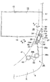
本発明に係るディスクカートリッジ1を構成するカートリッジ本体5は、図1乃至図3に示すように、このディスクカートリッジ1が装脱されるディスク記録及び/又は再生装置への挿入端側となる一側面である前面を円弧状部7として形成している。この円弧状部7は、図2に示すように、カートリッジ本体5のディスク収納部6に収納された光ディスク2の中心を中心Pとして半径Rを一定にしたほぼ半円の円弧状に形成されている。すなわち、円弧状部7は、カートリッジ本体5に収納された光ディスク2の半円に相当する部分と対向するような半円として形成されている。 As shown in FIGS. 1 to 3, the cartridge main body 5 constituting the disc cartridge 1 according to the present invention has one side surface on the insertion end side to the disc recording and / or reproducing apparatus from which the disc cartridge 1 is inserted and removed. Is formed as an arcuate portion 7. As shown in FIG. 2, the arc-shaped portion 7 is formed in a substantially semicircular arc shape with the radius R 1 being constant with the center P 0 being the center of the optical disc 2 accommodated in the disc accommodating portion 6 of the cartridge body 5. Has been. That is, the arc-shaped portion 7 is formed as a semicircle that faces a portion corresponding to a semicircle of the optical disc 2 stored in the cartridge body 5.

カートリッジ本体5の円弧状部7に連続する相対向する側面は、互いに平行な側面8,9として形成され、円弧状部7と対向する背面は、なだらかに湾曲して連続した湾曲部10として形成されている。   Opposite side surfaces that are continuous with the arc-shaped portion 7 of the cartridge body 5 are formed as side surfaces 8 and 9 that are parallel to each other, and a back surface that faces the arc-shaped portion 7 is gently curved and formed as a continuous curved portion 10. Has been.

本発明に係るディスクカートリッジ1は、挿入端側となる一の側面である前面を他の面に比し大きく湾曲したほぼ半円の円弧状部7としているので、カートリッジ挿脱口を介してスロットイン方式により装脱が行われるディスク記録及び/又は再生装置へ挿入を行う際、記録及び/又は再生装置への挿入方向が容易に判別できる。特に、掌内に収納できる程度に小型化したディスクカートリッジ1にあっては、手で握った感覚でも挿入方向の識別を行うことができるので、誤挿入を防止して正確にディスク記録及び/又は再生装置に装着することも可能となる。しかも、このディスクカートリッジ1は、後述するように、スロットイン方式のディスク記録及び/又は再生装置へ挿入操作が容易となるばかりか、確実な挿入操作を実現できる。   In the disk cartridge 1 according to the present invention, the front surface, which is one side that becomes the insertion end side, is formed as a substantially semicircular arc-shaped portion 7 that is largely curved as compared with the other surface. When inserting into a disc recording and / or reproducing apparatus in which loading and unloading is performed according to the method, the insertion direction into the recording and / or reproducing apparatus can be easily determined. In particular, in the case of the disc cartridge 1 that is small enough to be housed in the palm, it is possible to identify the insertion direction even with a hand gripping feeling. It can also be attached to a playback device. In addition, as will be described later, the disk cartridge 1 can be easily inserted into a slot-in type disk recording and / or reproducing apparatus, and can be surely inserted.

更に、本発明に係るディスクカートリッジ1は、挿入端側をほぼ半円の円弧状部7とし、更に加えて円弧状部7と対向する背面も湾曲部10としているので、収納する光ディスク2に対し一層の小型化が実現されている。   Furthermore, the disc cartridge 1 according to the present invention has a substantially semicircular arc-shaped portion 7 on the insertion end side and a curved portion 10 on the back surface facing the arc-shaped portion 7. Further downsizing has been realized.

カートリッジ本体5の下面側を構成する下ハーフ4の中央部には、図2及び図3に示すように、カートリッジ本体5に収納した光ディスク2の中心部に形成したセンター穴11及びその周縁を外方に臨ませる円形の中央開口部12が形成されている。中央開口部12には、ディスクカートリッジ1が装着されるディスク記録及び/又は再生装置側に設けられたディスク回転駆動機構の一部、例えばターンテーブルが進入する。   As shown in FIGS. 2 and 3, the center hole 11 formed at the center of the optical disk 2 housed in the cartridge body 5 and the periphery thereof are externally attached to the center of the lower half 4 constituting the lower surface side of the cartridge body 5. A circular central opening 12 is formed so as to face the direction. A part of a disk rotation driving mechanism provided on the side of the disk recording and / or reproducing apparatus on which the disk cartridge 1 is mounted, for example, a turntable, enters the central opening 12.

カートリッジ本体5の下面側を構成する下ハーフ4には、図2及び図3に示すように、記録及び/又は再生用開口部であるヘッド用開口部13が形成されている。ヘッド用開口部13は、カートリッジ本体5の一方の側面8に位置し、カートリッジ本体5に収納された光ディスク2の信号記録領域の一部を内外周に亘って外方に臨ませる足る大きさの矩形状に形成されている。すなわち、ヘッド用開口部13は、カートリッジ本体1の円弧状部7が形成された前面以外の直線状の平坦な面とされた側面8に臨んで形成されている。   As shown in FIGS. 2 and 3, a head opening 13 which is a recording and / or reproducing opening is formed in the lower half 4 constituting the lower surface side of the cartridge body 5. The head opening 13 is located on one side surface 8 of the cartridge body 5 and is large enough to allow a part of the signal recording area of the optical disk 2 accommodated in the cartridge body 5 to face outward over the inner and outer circumferences. It is formed in a rectangular shape. That is, the head opening 13 is formed so as to face the side surface 8 that is a straight flat surface other than the front surface where the arc-shaped portion 7 of the cartridge body 1 is formed.

本発明に係るディスクカートリッジ1は、ヘッド用開口部13を開閉するシャッタ部材15が移動可能に取り付けられている。シャッタ部材15は、ヘッド用開口部13を閉塞する足る大きさの矩形状に形成したされ平板状のシャッタ部16と、シャッタ部16の基板部側に形成された断面コ字状に形成された支持部17とを備える。   In the disk cartridge 1 according to the present invention, a shutter member 15 for opening and closing the head opening 13 is movably attached. The shutter member 15 is formed in a rectangular shape that is large enough to close the head opening 13, and is formed in a flat plate-shaped shutter portion 16 and a U-shaped cross section formed on the substrate portion side of the shutter portion 16. And a support portion 17.

なお、シャッタ部材15は、薄い金属板を打ち抜き折り曲げて形成され、若しくは合成樹脂材料を形成して形成されている。   The shutter member 15 is formed by punching and bending a thin metal plate, or formed by forming a synthetic resin material.

ところで、シャッタ部材15は、カートリッジ本体5を構成する上ハーフ3側を支持部17により支持し、ヘッド用開口部13を開閉する図2中矢印A方向及び矢印B方向に移動可能に支持されている。すなわち、シャッタ部材15は、図4に示すように、上ハーフ3に形成された立ち上がり周壁3aの一部をもって構成されたスライドガイド部18を支持部17により支持してカートリッジ本体5に移動可能に取り付けられている。   By the way, the shutter member 15 is supported so as to be movable in the directions of arrows A and B in FIG. Yes. That is, as shown in FIG. 4, the shutter member 15 is movable to the cartridge body 5 by supporting the slide guide portion 18 formed by a part of the rising peripheral wall 3 a formed in the upper half 3 by the support portion 17. It is attached.

そして、シャッタ部材15に設けられた支持部17には、図4及び図5に示すように、シャッタ部16の基端部から垂直に立ち上がり形成され連結片21が形成され、この連結片21の先端部にシャッタ部16側に向かって折り曲げられた第1の係合片22が設けられている。連結片21の両側には、第1の係合片22が形成された部分より一段低い位置でL字状に折り曲げされた第2の係合片23が設けられている。なお、第2の係合片23は、先端部側が第1の係合片22側に突出するようにL字状に折り曲げられている。   As shown in FIGS. 4 and 5, a support piece 17 provided on the shutter member 15 is vertically formed from the base end of the shutter part 16 to form a connection piece 21. A first engagement piece 22 that is bent toward the shutter portion 16 side is provided at the distal end portion. On both sides of the connecting piece 21, there are provided second engaging pieces 23 bent in an L shape at a position one step lower than the portion where the first engaging pieces 22 are formed. The second engagement piece 23 is bent in an L shape so that the tip end side protrudes toward the first engagement piece 22.

このシャッタ部材15は、図2に示すように、シャッタ部16をヘッド用開口部13上に延在するようにカートリッジ本体5に配設される。このとき、シャッタ部材15は、図6及び図7に示すように、支持部17に設けた第1の係合片22をスライドガイド部18の側面に形成した係合溝24に係合し、L字状の第2の係合片23をスライドガイド部18の先端側に係合させることにより、第1及び第2の係合片22,23によって支持部17を挟み込みように支持する。このように支持されたシャッタ部材15は、支持部17にガイドされ、ヘッド用開口部13を開閉する図2中矢印A方向及び矢印B方向に移動する。   As shown in FIG. 2, the shutter member 15 is disposed in the cartridge body 5 so that the shutter portion 16 extends over the head opening portion 13. At this time, as shown in FIGS. 6 and 7, the shutter member 15 engages the engagement groove 24 formed on the side surface of the slide guide portion 18 with the first engagement piece 22 provided in the support portion 17. By engaging the L-shaped second engagement piece 23 with the front end side of the slide guide portion 18, the support portion 17 is supported by the first and second engagement pieces 22 and 23. The shutter member 15 supported in this manner is guided by the support portion 17 and moves in the directions of arrows A and B in FIG.

なお、下ハーフ4のシャッタ部16が移動する領域には、凹状のシャッタスライド部19が形成されている。シャッタスライド部19は、シャッタ部16をカートリッジ本体5の表面から突出させないに足る深さをもって形成されている。   A concave shutter slide portion 19 is formed in an area where the shutter portion 16 of the lower half 4 moves. The shutter slide portion 19 is formed with a depth sufficient to prevent the shutter portion 16 from protruding from the surface of the cartridge body 5.

本発明に係るディスクカートリッジ1において、下ハーフ4に形成された立ち上がり周壁4aのヘッド用開口部13と対向する部分には、図4及び図7に示すように、切り欠き部25が形成されて開放されている。すなわち、ヘッド用開口部13は、カートリッジ本体5の内周側から外周縁に亘る領域が開放されて形成されている。 In the disk cartridge 1 according to the present invention, as shown in FIGS. 4 and 7, a notch 25 is formed in a portion of the rising peripheral wall 4 a formed in the lower half 4 that faces the head opening 13. It is open. In other words, the head opening 13 is formed by opening a region extending from the inner peripheral side of the cartridge body 5 to the outer peripheral edge.

また、上ハーフ3側に形成されたスライドガイド部18の少なくともヘッド用開口部13と対向する部分は、ディスク記録及び/又は再生装置内のカートリッジ装着部に高さ方向の位置決めが図られて装着されたディスクカートリッジ1内の光ディスク2がターンテーブル上に位置決めして装着されたとき、図7に示すように、この光ディスク2の下ハーフ4と対向する下面2aから突出しない高さHとして形成されている。 Further, at least a portion of the slide guide portion 18 formed on the upper half 3 side that faces the head opening portion 13 is mounted on the cartridge mounting portion in the disk recording and / or reproducing apparatus by positioning in the height direction. When the optical disc 2 in the disc cartridge 1 is positioned and mounted on the turntable, it is formed as a height H 1 that does not protrude from the lower surface 2a facing the lower half 4 of the optical disc 2 as shown in FIG. Has been.

このように形成されたディスクカートリッジ1は、シャッタ部材15が移動されてヘッド用開口部13が開放されたとき、光ディスク2に記録された情報信号を読み出すヘッド部である光ピックアップの全体をカートリッジ本体5内に位置させるばかりか、光ピックアップが光ディスク2の外周側を走査する位置に移動されたとき、後述するように、光ディスク2の信号記録領域を走査する光ビームを集光する対物レンズをカートリッジ本体5内に位置させながら、その他の光学ブロック部分をカートリッジ本体5の外方に位置させることができる。   The disk cartridge 1 formed in this manner is configured so that the entire optical pickup, which is a head portion for reading an information signal recorded on the optical disk 2 when the shutter member 15 is moved and the head opening 13 is opened, is a cartridge body. The objective lens for condensing the light beam for scanning the signal recording area of the optical disk 2 when the optical pickup is moved to a position for scanning the outer peripheral side of the optical disk 2 as well as being positioned within the cartridge 5 Other optical block portions can be positioned outside the cartridge main body 5 while being positioned in the main body 5.

その結果、本発明に係るディスクカートリッジ1は、光ピックアップを光ディスク2に近接させながら、カートリッジ本体5の内外に亘って位置させることができるので、光ディスク2の外周縁まで信号記録領域を形成することができ、光ディスク2に記録される記録容量を増大させることができる。更に、光ピックアップを光ディスク2に近接させることができることから、対物レンズの開口数(NA)を大きくでき、光ディスク2の信号記録領域に集光される光ビームのビームスポットを小さくできるので、光ディスク2に記録される情報信号の記録密度を向上できる。更にまた、記録容量の増大とともに記録密度の向上が実現できることから、一定量の記録容量を必要とする光ディスク2の小径化が実現できる。更にまた、光ピックアップをカートリッジ本体5の内外に亘るように位置させて光ディスク2の走査ができるので、カートリッジ本体5の小型化を実現でき、このディスクカートリッジ1を用いるディスク記録及び/又は再生装置の小型化も実現可能となる。   As a result, the disc cartridge 1 according to the present invention can be positioned over the inside and outside of the cartridge body 5 while bringing the optical pickup close to the optical disc 2, so that the signal recording area is formed up to the outer periphery of the optical disc 2. And the recording capacity recorded on the optical disc 2 can be increased. Furthermore, since the optical pickup can be brought close to the optical disc 2, the numerical aperture (NA) of the objective lens can be increased, and the beam spot of the light beam condensed on the signal recording area of the optical disc 2 can be reduced. It is possible to improve the recording density of information signals recorded on the recording medium. Furthermore, since the recording density can be improved as the recording capacity increases, the diameter of the optical disc 2 that requires a certain amount of recording capacity can be reduced. Furthermore, since the optical pickup 2 can be scanned by positioning the optical pickup so as to extend inside and outside the cartridge main body 5, the cartridge main body 5 can be reduced in size, and a disk recording and / or reproducing apparatus using the disk cartridge 1 can be realized. Miniaturization can also be realized.

本発明に係るディスクカートリッジ1において、ヘッド用開口部13を開閉するシャッタ部材15は、図1及び図2に示すように、カートリッジ本体5の平坦な側面8に沿って移動するように取り付けられている。したがって、シャッタ部材15は、支持部17を平坦な側面8に沿わせながら直線移動されるので、安定した移動操作が実現される。   In the disk cartridge 1 according to the present invention, the shutter member 15 that opens and closes the head opening 13 is attached so as to move along the flat side surface 8 of the cartridge body 5 as shown in FIGS. Yes. Therefore, the shutter member 15 is linearly moved while keeping the support portion 17 along the flat side surface 8, so that a stable movement operation is realized.

また、ヘッド用開口部13は、カートリッジ本体5の平坦な側面8に対向する位置に形成されているので、下ハーフ4側に形成される切り欠き部25が形成された部分も直線状の面とされている。したがって、切り欠き部25が形成され、カートリッジ本体5の外方に臨む側面8の側が開放されたヘッド用開口部13であっても、全体が矩形状に形成され、直線状の断面コ字状をなす支持部17を備えたシャッタ部材15により確実に閉塞することができる。   Further, since the head opening 13 is formed at a position facing the flat side surface 8 of the cartridge body 5, the portion where the notch 25 formed on the lower half 4 side is also formed in a linear surface. It is said that. Therefore, even if the opening 13 for the head is formed with the notch 25 and the side 8 facing the outside of the cartridge body 5 is opened, the whole is formed in a rectangular shape and has a straight U-shaped cross section. Therefore, the shutter member 15 having the support portion 17 can be reliably closed.

本発明に係るディスクカートリッジ1には、シャッタ部材15がヘッド用開口部13を閉塞する位置に移動されたとき、シャッタ部材15の移動を規制するロック機構27が設けられている。シャッタ部材15のロック機構27は、図5及び図8に示すように、シャッタ部材15に回動可能に取り付けられたロックレバー28と、このロックレバー28が係合するカートリッジ本体5側に設けられた係合部29とを備える。   The disk cartridge 1 according to the present invention is provided with a lock mechanism 27 that restricts the movement of the shutter member 15 when the shutter member 15 is moved to a position that closes the head opening 13. As shown in FIGS. 5 and 8, the lock mechanism 27 of the shutter member 15 is provided on a lock lever 28 rotatably attached to the shutter member 15 and on the cartridge body 5 side with which the lock lever 28 is engaged. And an engaging portion 29.

ロックレバー28は、図5及び図8に示すように、一端側の側縁に沿って押圧操作部30が立ち上がり形成され、他端側に係合部29に係合する係合片31が立ち上がり形成された長尺な板状の部材として形成されている。このロックレバー28は、シャッタ部材15に設けたロックレバー取付片32に回動可能に取り付けられる。ロックレバー取付片32は、シャッタ部材15のスライドガイド部18を構成する連結片21の上端縁からシャッタ部16の側方に突出するように形成されている。   As shown in FIGS. 5 and 8, the lock lever 28 has a pressing operation portion 30 rising along the side edge on one end side, and an engagement piece 31 engaging with the engagement portion 29 on the other end side. It is formed as a long plate-shaped member formed. The lock lever 28 is rotatably attached to a lock lever attachment piece 32 provided on the shutter member 15. The lock lever mounting piece 32 is formed so as to protrude from the upper end edge of the connecting piece 21 constituting the slide guide portion 18 of the shutter member 15 to the side of the shutter portion 16.

ロックレバー28は、図1、図6及び図8に示すように、一端側の押圧操作部30を連結片21のほぼ中央部に穿設した矩形状の窓部33に臨ませ、ほぼ中央部に穿設した枢支孔34をロックレバー取付片32に直立にした支軸35に枢支させ、この支軸35を中心に回動可能に取り付けられている。このとき、ロックレバー28の他端側に設けた係合片31は、ロックレバー取付片32に沿ってシャッタ部16の側方に突出されている。   As shown in FIGS. 1, 6, and 8, the lock lever 28 has a pressing operation portion 30 on one end side facing a rectangular window portion 33 formed in a substantially central portion of the connecting piece 21, and is substantially in the central portion. The pivot support hole 34 drilled in the shaft is pivotally supported on a support shaft 35 upright on the lock lever mounting piece 32, and is mounted so as to be rotatable about the support shaft 35. At this time, the engagement piece 31 provided on the other end side of the lock lever 28 protrudes to the side of the shutter portion 16 along the lock lever attachment piece 32.

なお、シャッタ部材15の連結片21に設けた窓部33は、このディスクカートリッジ1が装着されるディスク記録及び/又は再生装置側に設けられたシャッタ部材15の移動を規制するシャッタ部材移動規制バネが係合する部分となる。   Note that a window 33 provided on the connecting piece 21 of the shutter member 15 is a shutter member movement regulating spring that regulates the movement of the shutter member 15 provided on the disk recording and / or reproducing apparatus side where the disk cartridge 1 is mounted. Is the part that engages.

シャッタ部材15に支持されたロックレバー28は、支軸35に巻回された回動付勢バネ37により、押圧操作部30を窓部33から突出させる図8中矢印C方向に回動付勢されている。回動付勢バネ37は、捩りコイルバネにより構成され、一方のアーム部37aを押圧操作部30の係止させ、他方のアーム部37bをシャッタ部材15側の連結片21の内面に係止させることによって、ロックレバー28を図8中矢印C方向に回動付勢している。   The lock lever 28 supported by the shutter member 15 is urged to rotate in the direction of arrow C in FIG. 8 by which the pressing operation unit 30 protrudes from the window 33 by a rotation urging spring 37 wound around the support shaft 35. Has been. The rotation urging spring 37 is constituted by a torsion coil spring, and one arm portion 37a is locked to the pressing operation portion 30 and the other arm portion 37b is locked to the inner surface of the connecting piece 21 on the shutter member 15 side. Thus, the lock lever 28 is urged to rotate in the direction of arrow C in FIG.

なお、ロックレバー28は、押圧操作部30が形成された一端側を連結片21に当接させることにより回動付勢バネ37による回動付勢位置が規制されている。   The lock lever 28 is restricted in its rotation biasing position by the rotation biasing spring 37 by abutting one end side where the pressing operation portion 30 is formed on the connecting piece 21.

上述のようにロックレバー28を取り付けたシャッタ部材15は、前述したように、支持部17を上ハーフ3に支持させることによりカートリッジ本体5に移動可能に取り付けられる。   As described above, the shutter member 15 to which the lock lever 28 is attached as described above is movably attached to the cartridge body 5 by supporting the support portion 17 on the upper half 3.

ロックレバー28は、シャッタ部材15が図6及び図8に示すようにヘッド用開口部13を閉塞する位置にあるとき、回動付勢バネ37の付勢力を受けて図8中矢印C方向に回動され、押圧操作部30を連結片21に設けた窓部33に進入させている。このとき、ロックレバー28は、他端側に形成した係合片31をカートリッジ本体5側に設けた係合部29に係合させ、シャッタ部材15の移動を規制し、ヘッド用開口部13をシャッタ部16によって閉塞した状態に保持している。   When the shutter member 15 is in a position to close the head opening 13 as shown in FIGS. 6 and 8, the lock lever 28 receives the urging force of the rotation urging spring 37 in the direction of arrow C in FIG. It is rotated and the pressing operation part 30 is made to enter the window part 33 provided in the connecting piece 21. At this time, the lock lever 28 engages the engagement piece 31 formed on the other end side with the engagement portion 29 provided on the cartridge body 5 side, restricts the movement of the shutter member 15, and opens the head opening 13. The shutter 16 is held closed.

カートリッジ本体5側に設けられる係合部29は、ディスク収納部6の領域外の下ハーフ4の内面であって、シャッタ部材15が閉塞位置にあるときにロックレバー28の係合片31が係合可能な位置に形成されている。係合部29は、下ハーフ4と一体に形成されている。この係合部29には、一側面を開放した係合凹部29aが形成され、この係合凹部29aにロックレバー28側の係合片31が係合する。   The engagement portion 29 provided on the cartridge body 5 side is the inner surface of the lower half 4 outside the area of the disk storage portion 6, and the engagement piece 31 of the lock lever 28 is engaged when the shutter member 15 is in the closed position. It is formed at a position where it can be combined. The engaging portion 29 is formed integrally with the lower half 4. The engaging portion 29 is formed with an engaging concave portion 29a having one side open, and the engaging piece 31 on the lock lever 28 side is engaged with the engaging concave portion 29a.

シャッタ部材15を閉塞位置にロックしたロックレバー28は、ディスクカートリッジ1がディスク記録及び/又は再生装置に挿入されるとき、連結片21に設けた窓部33に進入し係合するシャッタ部材移動規制バネにより押圧操作部30が押圧され、回動付勢バネ37の付勢力に抗して図8中矢印D方向に回転される。ロックレバー28が図8中矢印D方向に回転すると、図9に示すように、係合片31が係合部29の係合凹部29aから離脱し、シャッタ部材15のロックが解除され、シャッタ部材15は、ヘッド用開口部13を開放する方向の図2中矢印A方向に移動可能となる。   The lock lever 28 that locks the shutter member 15 in the closed position restricts the movement of the shutter member that enters and engages the window 33 provided in the connecting piece 21 when the disc cartridge 1 is inserted into the disc recording and / or reproducing apparatus. The pressing operation unit 30 is pressed by the spring and rotated in the direction of arrow D in FIG. 8 against the urging force of the rotation urging spring 37. When the lock lever 28 rotates in the direction of arrow D in FIG. 8, as shown in FIG. 9, the engagement piece 31 is disengaged from the engagement recess 29a of the engagement portion 29, the shutter member 15 is unlocked, and the shutter member 15 is movable in the direction of arrow A in FIG. 2 in the direction of opening the head opening 13.

なお、ヘッド用開口部13の開閉は、カートリッジ本体5とシャッタ部材15とが相対移動されることによって行われるが、ヘッド用開口部13の開閉操作の詳細については後述する。   The opening / closing of the head opening 13 is performed by relative movement of the cartridge body 5 and the shutter member 15, and details of the opening / closing operation of the head opening 13 will be described later.

上述したシャッタ部材ロック機構27は、シャッタ部材15を閉塞位置にロックするロックレバー28を、カートリッジ本体5に対し移動するシャッタ部材15に取り付けているので、ヘッド用開口部13の開閉に追随してシャッタ部材15と一体に移動させることができる。その結果、ロックレバー28は、シャッタ部材15がヘッド用開口部13を閉塞した位置にあるとき、少なくとも押圧操作部30側をヘッド用開口部13上に位置させて配置できるので、ディスクカートリッジ1の小型化を実現できる。すなわち、ロックレバー28をカートリッジ本体5側に設けたときには、ロックレバー28の全体を配置するための空間をカートリッジ本体5側に設ける必要があるが、本発明に係るディスクカートリッジ1は、その必要がなく、カートリッジ本体5側には、ロックレバー28の一部が係合する係合部29を設けるのみで足るので、カートリッジ本体5の一層の小型化を達成することができる。   In the shutter member locking mechanism 27 described above, the lock lever 28 that locks the shutter member 15 in the closed position is attached to the shutter member 15 that moves relative to the cartridge main body 5, so that the opening 13 for the head is followed. It can be moved integrally with the shutter member 15. As a result, when the shutter member 15 is in a position where the head opening 13 is closed, the lock lever 28 can be disposed with at least the pressing operation unit 30 side positioned on the head opening 13. Miniaturization can be realized. That is, when the lock lever 28 is provided on the cartridge main body 5 side, it is necessary to provide a space for arranging the entire lock lever 28 on the cartridge main body 5 side. However, the disc cartridge 1 according to the present invention requires that. In addition, since it is only necessary to provide the engaging portion 29 with which a part of the lock lever 28 is engaged on the cartridge main body 5 side, further downsizing of the cartridge main body 5 can be achieved.

本発明に係るディスクカートリッジ1は、ヘッド用開口部13を開閉するシャッタ部材15の確実な移動を実現し、更に、シャッタ部材15を、ヘッド用開口部13を開放した位置又は閉塞した位置に確実に保持するようにするシャッタ開閉機構38を備えるようにしてもよい。   The disk cartridge 1 according to the present invention realizes a reliable movement of the shutter member 15 that opens and closes the head opening 13, and further ensures that the shutter member 15 is in a position where the head opening 13 is opened or closed. A shutter opening / closing mechanism 38 may be provided to hold the shutter.

このシャッタ開閉機構38は、シャッタ部材15を、ヘッド用開口部13を開放する方向及び閉塞する方向の2方向に選択的に移動付勢する2方向付勢部材を用いて構成される。2方向付勢部材には、具体的には、図8に示すように、捩りコイルバネ39が用いられる。捩りコイルバネ39は、シャッタ部材15とカートリッジ本体5との間に懸架される。この捩りコイルバネ39は、図8に示すように、シャッタ部材15がヘッド用開口部13を開放する方向に移動する側に位置して配設され、一方のアーム部39aの先端をロック板取付片32の先端に穿設した係合孔40に係合させ、他方のアーム部39bの先端に設けた環状部41をカートリッジ本体5の内面に突設した支持ピン42に係合させて取り付けられている。   The shutter opening / closing mechanism 38 includes a two-way urging member that selectively moves and urges the shutter member 15 in two directions, that is, a direction in which the head opening 13 is opened and a direction in which the head opening 13 is closed. Specifically, as shown in FIG. 8, a torsion coil spring 39 is used for the two-way urging member. The torsion coil spring 39 is suspended between the shutter member 15 and the cartridge body 5. As shown in FIG. 8, the torsion coil spring 39 is disposed on the side where the shutter member 15 moves in the direction of opening the head opening 13, and the tip of one arm 39a is connected to the lock plate mounting piece. The annular portion 41 provided at the tip of the other arm portion 39b is engaged with the support pin 42 protruding from the inner surface of the cartridge main body 5 and attached. Yes.

捩りコイルバネ39は、シャッタ部材15がヘッド用開口部13を閉塞する位置にあるときには、ヘッド用開口部13を閉塞した状態を維持するように図8中矢印B方向に付勢している。この捩りコイルバネ39は、ディスクカートリッジ1がディスク記録及び/又は再生装置に装着され、シャッタ部材ロック機構27によるロックが解除されてシャッタ部材15がカートリッジ本体に5に対しヘッド用開口部13を開放する方向の図8中矢印A方向に相対移動していくと、固定されていない中心部に形成したコイル部39cの位置がシャッタ部材15の移動方向の矢印A方向に移動していく。捩りコイルバネ39は、コイル部39cが更に矢印A方向に移動し、図10に示すように、シャッタ部材15の移動方向側に位置する支持ピン42の位置を超えると付勢方向が反転される。捩りコイルバネ39は、付勢方向が反転されると、シャッタ部材15を図10中矢印A方向に移動するように付勢し、図11及び図12に示すように、ヘッド用開口部13を開放するする方向の矢印A方向に移動してヘッド用開口部13を開放した位置に保持する。   The torsion coil spring 39 is biased in the direction of arrow B in FIG. 8 so as to maintain the state in which the head opening 13 is closed when the shutter member 15 is in a position to close the head opening 13. The torsion coil spring 39 is used when the disk cartridge 1 is mounted on a disk recording and / or reproducing apparatus, the shutter member lock mechanism 27 is unlocked, and the shutter member 15 opens the head opening 13 to the cartridge body 5. When the relative movement is made in the direction of arrow A in FIG. 8, the position of the coil portion 39 c formed at the unfixed center portion moves in the direction of arrow A of the movement direction of the shutter member 15. When the coil portion 39c further moves in the direction of arrow A and the torsion coil spring 39 exceeds the position of the support pin 42 located on the moving direction side of the shutter member 15 as shown in FIG. When the urging direction is reversed, the torsion coil spring 39 urges the shutter member 15 to move in the direction of arrow A in FIG. 10, and opens the head opening 13 as shown in FIGS. The head opening 13 is held in the open position by moving in the direction of arrow A.

シャッタ部材15がヘッド用開口部13を開放した位置に保持されたディスクカートリッジ1をディスク記録及び/又は再生装置から取り出すイジェクト操作を行うと、シャッタ部材15はカートリッジ本体5に対し図10中矢印B方向に移動していき、中心のコイル部39cも同方向の矢印B方向に移動していく。捩りコイルバネ39は、シャッタ部材15が更に矢印B方向方向に移動し、シャッタ部材15の移動方向側に位置する支持ピン42の位置を超えると付勢方向が反転される。捩りコイルバネ39は、付勢方向が反転されると、シャッタ部材15を図9中矢印B方向に移動するように付勢し、ヘッド用開口部13を閉塞する方向に移動してヘッド用開口部13を閉塞した位置に保持する。   When an ejection operation is performed to take out the disk cartridge 1 held at the position where the shutter member 15 opens the head opening 13 from the disk recording and / or reproducing apparatus, the shutter member 15 moves the arrow B in FIG. The central coil portion 39c also moves in the direction of arrow B in the same direction. When the shutter member 15 further moves in the direction of arrow B and the torsion coil spring 39 exceeds the position of the support pin 42 located on the moving direction side of the shutter member 15, the biasing direction is reversed. When the urging direction is reversed, the torsion coil spring 39 urges the shutter member 15 to move in the direction of arrow B in FIG. 9 and moves in a direction to close the head opening 13 to move the head opening. 13 is held in the closed position.

このように2方向付勢部材を構成する捩りコイルバネ39により付勢されたシャッタ部材15は、ヘッド用開口部13を閉塞した位置及び開放した位置のそれぞれの位置に捩りコイルバネ39の付勢力を受けて支持されるので、確実にヘッド用開口部13を閉塞し又は開放した状態を維持できる。   Thus, the shutter member 15 urged by the torsion coil spring 39 constituting the two-way urging member receives the urging force of the torsion coil spring 39 at each of the positions where the head opening 13 is closed and opened. Therefore, it is possible to reliably maintain the state where the head opening 13 is closed or opened.

本発明が適用されたディスクカートリッジ1においては、上述したように、シャッタ部材15を閉塞位置にロックするシャッタ部材ロック機構27とともに、シャッタ部材15を2方向に選択的に移動付勢する2方向付勢部材を備えたシャッタ開閉機構38を備えることにより、シャッタ部材15をヘッド用開口部13の閉塞位置に確実に保持でき、しかも、確実なヘッド用開口部13の開閉操作が実現できる。   In the disk cartridge 1 to which the present invention is applied, as described above, together with the shutter member lock mechanism 27 that locks the shutter member 15 in the closed position, the shutter member 15 is selectively moved in two directions and biased. By providing the shutter opening / closing mechanism 38 including the urging member, the shutter member 15 can be reliably held at the closed position of the head opening 13 and a reliable opening / closing operation of the head opening 13 can be realized.

なお、ヘッド用開口部13を確実に閉塞するためには、シャッタ部材ロック機構27を設けるのみでよい。また、シャッタ部材15の安定した開閉動作を実現し、ヘッド用開口部13を閉塞した状態を維持し、更にヘッド用開口部13を開放した状態を確実に維持するようにするためには、2方向付勢部材を備えたシャッタ開閉機構38のみを設けるようにしてもよい。   In order to securely close the head opening 13, it is only necessary to provide the shutter member lock mechanism 27. Further, in order to realize a stable opening / closing operation of the shutter member 15, to maintain the state in which the head opening 13 is closed, and to reliably maintain the state in which the head opening 13 is opened, 2 Only the shutter opening / closing mechanism 38 provided with the direction biasing member may be provided.

本発明に係るディスクカートリッジ1は、シャッタ部材15が取り付けられたカートリッジ本体5の一方の側面8には、図1、図6及び図12に示すように、ディスク記録及び/又は再生装置側に設けられたシャッタ部材解放操作片が進入するガイド溝43が設けられいる。   The disc cartridge 1 according to the present invention is provided on one side 8 of the cartridge body 5 to which the shutter member 15 is attached, on the disc recording and / or reproducing device side, as shown in FIGS. A guide groove 43 into which the shutter member release operation piece is inserted is provided.

カートリッジ本体5の下面側であって、湾曲部10とされた背面側の両側には、図2及び図3に示すように、ディスク記録及び/又は再生装置側に設けた位置決めピンが係合する第1及び第2の位置決め孔43,44が設けられている。なお、第2の位置決め孔44は、位置決めピンの係合位置を調整するため、シャッタ部材15の移動方向と直交する幅方向を長径とする長孔として形成されている。   As shown in FIGS. 2 and 3, positioning pins provided on the disk recording and / or reproducing device side engage with both sides of the lower surface side of the cartridge main body 5 on the back side which is the curved portion 10. First and second positioning holes 43 and 44 are provided. The second positioning hole 44 is formed as a long hole having a major axis in the width direction orthogonal to the moving direction of the shutter member 15 in order to adjust the engaging position of the positioning pin.

更に、カートリッジ本体5の円弧状部7の相対向する側面8,9側には、図1及び図2に示すように、このディスクカートリッジ1が装着されるディスク記録及び/又は再生装置側に設けられるカートリッジローディング機構の一部が係合するローディング用の係合凹部45,46が設けられている。   Further, as shown in FIGS. 1 and 2, the side surfaces 8 and 9 of the arcuate portion 7 of the cartridge body 5 are provided on the side of the disk recording and / or reproducing apparatus on which the disk cartridge 1 is mounted. The engaging recesses 45 and 46 for loading with which a part of the cartridge loading mechanism to be engaged is engaged are provided.

更にまた、カートリッジ本体5の円弧状部7の他方の側面9側に位置する部分には、図3に示すように、記録及び/又は再生装置側に設けられるイジェクト機構の一部が係合するイジェクト用の係合凹部47が設けられている。 Furthermore, as shown in FIG. 3 , a part of the ejection mechanism provided on the recording and / or reproducing apparatus side engages with the portion located on the other side surface 9 side of the arcuate portion 7 of the cartridge body 5 . An engaging recess 47 for ejection is provided.

更にまた、カートリッジ本体5の側面8,9、あるいは底面には、収納される光ディスク2の種類を識別するための識別孔や識別凹部が必要に応じて設けられる。   Furthermore, identification holes and identification recesses for identifying the type of the optical disk 2 to be accommodated are provided on the side surfaces 8, 9 or the bottom surface of the cartridge body 5 as necessary.

次に、本発明に係るディスクカートリッジ1が用いられるディスク記録及び/又は再生装置の一例を説明する。   Next, an example of a disk recording and / or reproducing apparatus in which the disk cartridge 1 according to the present invention is used will be described.

本発明に係るディスクカートリッジ1は、例えばテレビジョンゲームを実行するプログラムデータやビデオデータが記録された光ディスク2が収納される。そこで、この種の光ディスク2を収納した本発明に係るディスクカートリッジ1を用いるディスク記録及び/又は再生装置としては、図13に示すように、ディスクカートリッジ1が装着され、少なくとも光ディスク2に記録されたデータを再生するディスクドライブ部を内蔵した装置本体51と、光ディスク2から再生された画像データや文字データを表示するディスプレイ部52を備えたディスクドライブ装置50が用いられる。   The disc cartridge 1 according to the present invention stores an optical disc 2 on which program data for executing a television game and video data are recorded, for example. Therefore, as a disk recording and / or reproducing apparatus using the disk cartridge 1 according to the present invention in which this type of optical disk 2 is housed, the disk cartridge 1 is mounted and recorded at least on the optical disk 2 as shown in FIG. A disk drive device 50 having a device main body 51 incorporating a disk drive unit for reproducing data and a display unit 52 for displaying image data and character data reproduced from the optical disk 2 is used.

図13に示すディスクドライブ装置50は、ディスクドライブ部を内蔵した装置本体51内には、図示はしないが、ディスクカートリッジ1をディスクドライブ部に装着するためのカートリッジホルダを備えたカートリッジローディング機構が設けられている。装置本体1の一側面を構成する前面には、カートリッジホルダに対しディスクカートリッジ1を挿入し、カセットホルダに装着されたディスクカートリッジ1をイジェクトするためのカートリッジ挿脱口53が設けられている。カートリッジ挿脱口53は、ディスクカートリッジ1の装脱を行うに足る大きさの開口部として形成され、ここに挿入されるディスクカートリッジ1の幅Wよりわずかに大きい幅Wを有し、ディスクカートリッジ1の厚さDよりわずかに大きな高さHを有する矩形状に形成されている。装置本体51内には、カートリッジ挿脱口53に対向してカートリッジホルダ54が配設されている。 The disk drive device 50 shown in FIG. 13 is provided with a cartridge loading mechanism having a cartridge holder for mounting the disk cartridge 1 in the disk drive unit (not shown) in the apparatus main body 51 incorporating the disk drive unit. It has been. A cartridge insertion / removal port 53 for inserting the disk cartridge 1 into the cartridge holder and ejecting the disk cartridge 1 mounted on the cassette holder is provided on the front surface constituting one side of the apparatus main body 1. The cartridge insertion / removal port 53 is formed as an opening that is large enough to load / unload the disk cartridge 1, and has a width W 2 that is slightly larger than the width W 1 of the disk cartridge 1 inserted therein. It is formed in a rectangular shape having a height H 2 slightly larger than a thickness D 1 of 1 . A cartridge holder 54 is disposed in the apparatus main body 51 so as to face the cartridge insertion / removal port 53.

装置本体51の前面側の一側には、カートリッジホルダ54に保持されたディスクカートリッジ1をイジェクト操作するためのイジェクトボタン55が設けられている。   An eject button 55 for ejecting the disc cartridge 1 held by the cartridge holder 54 is provided on one side of the front side of the apparatus main body 51.

装置本体51の上面の一方の側には、例えばテレビジョンゲームを実行する際に用いられる制御スイッチの操作ボタン56,57が設けられ、他方の側には、ディスプレイ部52に表示される画像をスクロールするための制御キー58が設けられ、更に、光ディスク2から再生されるオーディオ信号を放射するスピーカ59が設けられている。   On one side of the upper surface of the apparatus main body 51, for example, operation buttons 56 and 57 of a control switch used when executing a television game are provided, and an image displayed on the display unit 52 is displayed on the other side. A control key 58 for scrolling is provided, and a speaker 59 for emitting an audio signal reproduced from the optical disc 2 is further provided.

装置本体51には、図示は省略するが、ディスクドライブ部を制御するための再生ボタン等の制御ボビンや電源スイッチ操作ボタン等が設けられている。   Although not shown, the device main body 51 is provided with a control bobbin such as a playback button for controlling the disk drive unit, a power switch operation button, and the like.

ディスプレイ部52は、装置本体51のカートリッジ挿脱口53が設けられた前面側とは反対側の背面側に位置して、ヒンジ機構60を介して装置本体51に対し回動可能に取り付けられている。ディスプレイ部52は、装置本体51側に回動されることにより、装置本体51の上面に重ね合わせられる。ディスプレイ部52は、液晶表示パネルを用いて構成されている。   The display unit 52 is positioned on the back side opposite to the front side where the cartridge insertion / extraction port 53 of the apparatus main body 51 is provided, and is rotatably attached to the apparatus main body 51 via a hinge mechanism 60. . The display unit 52 is superimposed on the upper surface of the apparatus main body 51 by being rotated toward the apparatus main body 51 side. The display unit 52 is configured using a liquid crystal display panel.

次に、上述のような構成を備えたディスクドライブ装置50に本発明に係るディスクカートリッジ1を装着する状態を説明する。   Next, a state where the disk cartridge 1 according to the present invention is mounted on the disk drive device 50 having the above-described configuration will be described.

ディスクカートリッジ1をディスクドライブ装置50に装着するには、図13に示すように、円弧状部10が形成された先端側を挿入端としてカートリッジ挿脱口53から装置本体51内に挿入され、カートリッジホルダ54に保持される。   To mount the disc cartridge 1 in the disc drive device 50, as shown in FIG. 13, the disc cartridge 1 is inserted into the device main body 51 from the cartridge insertion / removal port 53 with the distal end side where the arc-shaped portion 10 is formed as the insertion end. 54.

ところで、本発明に係るディスクカートリッジ1は、カートリッジ挿脱口53への挿入端側がほぼ半円の円弧状部10として形成されているので、カートリッジ挿脱口53の幅方向の中心線Pに対し幅方向の中心線Pを大きく傾斜して挿入した場合でも、円滑にカートリッジ挿脱口53に挿入し、確実にカートリッジホルダ54に保持できる。 Meanwhile, the disc cartridge 1 according to the present invention, since the insertion end side into the cartridge slot 53 is formed substantially as an arc-shaped portion 10 of the semicircle, the width with respect to the width direction center line P 1 of the cartridge slot 53 even when inserted by increasing the inclination direction of the center line P 2, and smoothly inserted into the cartridge slot 53, it can be held securely in the cartridge holder 54.

すなわち、挿入端がほぼ半円の円弧状部10とされたディスクカートリッジ1は、図14又は図15に示すように、カートリッジ挿脱口53の幅方向の中心線Pに対し幅方向の中心線Pを左右のいずれかの方向に45度程度まで傾斜した状態でカートリッジ挿脱口53に挿入された場合であっても、半円の円弧状部10側を大きく装置本体51に挿入できる。このとき、ディスクカートリッジ1は、カートリッジ挿脱口53への挿入途中にカートリッジ挿脱口53のいずれか一方の側面に当接する円弧状部10の一部を中心にして、図16に示すように、各中心線P,Pを一致させる方向に回転して容易に姿勢を正しくすることができる。このように、本発明に係るディスクカートリッジ1は、カートリッジ挿脱口53に対する挿入方向が大きく変位しても、確実にカートリッジホルダ54への装着が可能となる。 That is, the disc cartridge 1 having the insertion end of the arc-shaped portion 10 having a substantially semicircular shape has a center line in the width direction with respect to the center line P 1 in the width direction of the cartridge insertion / removal port 53 as shown in FIG. even when it is inserted into the cartridge slot 53 in a state inclined with P 2 to about 45 degrees in either direction of the right and left, it can be inserted into the larger apparatus main body 51 an arcuate portion 10 side of the semicircle. At this time, as shown in FIG. 16, the disc cartridge 1 is centered on a part of the arcuate portion 10 that is in contact with any one side surface of the cartridge insertion / removal port 53 during insertion into the cartridge insertion / removal port 53. The posture can be easily corrected by rotating in the direction in which the center lines P 1 and P 2 coincide. As described above, the disc cartridge 1 according to the present invention can be securely mounted to the cartridge holder 54 even if the insertion direction with respect to the cartridge insertion / removal port 53 is greatly displaced.

そして、カートリッジホルダ54に挿入されたディスクカートリッジ1は、更にカートリッジホルダ54内に挿入されることにより、シャッタ部材15がカートリッジ本体5に対し相対移動され、ヘッド用開口部13が開放される。すなわち、ディスクカートリッジ1が、図17に示すように、カートリッジホルダ54の途中まで挿入されると、カートリッジホルダ54の一方の側に設けた断面L字状のカートリッジ支持部61の側壁の一部を切り起こして形成したシャッタ部材移動規制バネ62の一部がシャッタ部材15の連結片21に形成した窓部33に進入して押圧操作部30を押圧し、ロックレバー28を前述した図9中中矢印D方向に回転させる。ロックレバー28は、図9中矢印D方向に回転されると、係合片31の係合部29に対する係合が解除されシャッタ部材15のカートリッジ本体5に対するロックを解除する。シャッタ部材15は、カートリッジ本体5に対するロックが解除されると、カートリッジ本体5に対し相対的に移動可能な状態となる。   The disc cartridge 1 inserted into the cartridge holder 54 is further inserted into the cartridge holder 54, whereby the shutter member 15 is moved relative to the cartridge body 5 and the head opening 13 is opened. That is, as shown in FIG. 17, when the disc cartridge 1 is inserted partway through the cartridge holder 54, a part of the side wall of the L-shaped cartridge support portion 61 provided on one side of the cartridge holder 54 is removed. A part of the shutter member movement regulating spring 62 formed by cutting and raising enters the window 33 formed in the connecting piece 21 of the shutter member 15 and presses the pressing operation unit 30, and the lock lever 28 in FIG. Rotate in the direction of arrow D. When the lock lever 28 is rotated in the direction of arrow D in FIG. 9, the engagement of the engagement piece 31 with the engagement portion 29 is released and the lock of the shutter member 15 with respect to the cartridge body 5 is released. The shutter member 15 is movable relative to the cartridge body 5 when the lock on the cartridge body 5 is released.

本発明に係るディスクカートリッジ1が装着されるカートリッジホルダ54には、更にシャッタ解放操作片63が設けられている。シャッタ解放操作片63は、ディスクカートリッジ1がシャッタ部材15のロックが解除される位置まで挿入されたとき、カートリッジ本体5の一方の側面8に形成したガイド溝43に進入し、シャッタ部材15の一側に当接する位置に設けられている。   The cartridge holder 54 to which the disc cartridge 1 according to the present invention is mounted is further provided with a shutter release operation piece 63. When the disc cartridge 1 is inserted to a position where the shutter member 15 is unlocked, the shutter release operation piece 63 enters the guide groove 43 formed on one side surface 8 of the cartridge body 5, and It is provided at a position that contacts the side.

そして、ディスクカートリッジ1は、シャッタ部材15のロックが解除される位置までカートリッジホルダ54に挿入されると、図17に示すように、シャッタ解放操作片63がシャッタ部材15の一側に当接し、シャッタ部材15のカートリッジ本体5に対する移動を規制した状態となる。この図17に示す位置から更にディスクカートリッジ1をカートリッジホルダ54の内方に向かう矢印E方向に挿入すると、カートリッジ本体5が矢印E方向に移動し、図18に示すように、ヘッド用開口部13が開放される。   When the disc cartridge 1 is inserted into the cartridge holder 54 to a position where the shutter member 15 is unlocked, the shutter release operation piece 63 comes into contact with one side of the shutter member 15 as shown in FIG. The movement of the shutter member 15 relative to the cartridge body 5 is restricted. When the disc cartridge 1 is further inserted from the position shown in FIG. 17 in the direction of arrow E toward the inside of the cartridge holder 54, the cartridge main body 5 moves in the direction of arrow E, and as shown in FIG. Is released.

ディスクカートリッジ1は、シャッタ部材15の移動が規制された状態で、カートリッジ本体5がヘッド用開口部13を開放する図17中矢印E方向に移動するとき、前述した図9及び図10に示すように、シャッタ開閉機構38を構成する捩りコイルバネ39が偏倚される。捩りコイルバネ39は、カートリッジ本体5が図17中矢印E方向に移動され、コイル部39cがシャッタ部材15の移動方向側に位置する支持ピン42の位置を超える位置まで偏倚されると、付勢方向が反転され、シャッタ部材15をカートリッジ本体5の移動方向とは逆方向の図17中矢印F方向に移動させ、前述した図11及び図12、更に図18に示すように、ヘッド用開口部13を開放する。このとき、シャッタ部材15は、捩りコイルバネ39によりヘッド用開口部13を開放するように付勢されているので、確実にヘッド用開口部13を開放した状態に維持する。   When the cartridge main body 5 moves in the direction of arrow E in FIG. 17 where the head opening 13 is opened while the movement of the shutter member 15 is restricted, the disk cartridge 1 is as shown in FIGS. 9 and 10 described above. Further, the torsion coil spring 39 constituting the shutter opening / closing mechanism 38 is biased. When the cartridge body 5 is moved in the direction of arrow E in FIG. 17 and the coil portion 39c is biased to a position exceeding the position of the support pin 42 located on the moving direction side of the shutter member 15, the torsion coil spring 39 is biased. Is reversed, and the shutter member 15 is moved in the direction of arrow F in FIG. 17 opposite to the direction of movement of the cartridge body 5, and as shown in FIGS. 11 and 12, and FIG. Is released. At this time, the shutter member 15 is biased to open the head opening 13 by the torsion coil spring 39, so that the head opening 13 is reliably maintained in the open state.

上述のような操作をもってヘッド用開口部13が開放されてカートリッジホルダ54に挿入されたディスクカートリッジ1は、ディスクドライブ装置50内に設けられたカートリッジ装着部に位置決めして装着される。このとき、光ディスク2は、ディスクドライブ部に位置決めして装着される。ここで、ディスクドライブ部を駆動することによって、光ディスク2に記録されたプログラムデータが再生され、プログラムが実行される。   The disk cartridge 1 inserted into the cartridge holder 54 with the head opening 13 opened by the operation as described above is positioned and mounted on a cartridge mounting section provided in the disk drive device 50. At this time, the optical disk 2 is positioned and mounted on the disk drive unit. Here, by driving the disk drive unit, the program data recorded on the optical disk 2 is reproduced and the program is executed.

そして、光ディスク2の再生を行った後、ディスクドライブ装置50に装着されたディスクカートリッジ1をイジェクトするには、イジェクトボタン55を操作することによって行われる。イジェクトボタン55が操作されると、カートリッジ装着部に装着されたディスクカートリッジ1のイジェクト操作が実行される。イジェクト操作が実行されると、更なる詳細な説明は省略するが、上述した動作とは逆の動作をもってシャッタ部材15がカートリッジ本体5に対し相対移動され、ヘッド用開口部13を閉塞し、このヘッド用開口部13を閉塞した位置にロックされる初期状態に復帰する。このシャッタ部材15の閉塞位置への復帰動作とともにカートリッジ挿脱口53からの排出が行われ、ディスクドライブ装置50に装着されたディスクカートリッジ1のイジェクトが完了する。   Then, after the optical disk 2 is reproduced, the disk cartridge 1 loaded in the disk drive device 50 is ejected by operating the eject button 55. When the eject button 55 is operated, the eject operation of the disk cartridge 1 mounted on the cartridge mounting portion is executed. When the ejection operation is executed, further detailed explanation is omitted, but the shutter member 15 is moved relative to the cartridge body 5 by an operation opposite to the above-described operation, and the head opening 13 is closed. It returns to the initial state where it is locked at the position where the head opening 13 is closed. As the shutter member 15 returns to the closed position, the cartridge is ejected from the cartridge insertion / removal port 53, and the ejection of the disk cartridge 1 attached to the disk drive device 50 is completed.

本発明に係るディスクカートリッジ1がディスクドライブ装置50に装着される状態を更に説明すると、ディスクカートリッジ1は、図19に示すように、ディスクドライブ装置50に設けたディスク回転駆動機構65を構成するターンテーブル66が進入する中央開口部12が形成され下面側を装着面として装置本体51内に構成されたカートリッジ装着部67に装着される。   The state where the disk cartridge 1 according to the present invention is mounted in the disk drive device 50 will be further described. The disk cartridge 1 is a turn constituting a disk rotation drive mechanism 65 provided in the disk drive device 50 as shown in FIG. A central opening 12 into which the table 66 enters is formed, and is mounted on a cartridge mounting portion 67 configured in the apparatus main body 51 with the lower surface side as a mounting surface.

なお、カートリッジ装着部67は、ディスク回転駆動機構65や、光ディスク2に記録されたデータの再生を行う光ピックアップ68が配設されるベース69上に構成されている。カートリッジ装着部67には、ディスクカートリッジ1の平面方向の位置決めを行う位置決めピン70と、図示はしないが高さ方向の位置決め行う位置決め突起が設けられている。ディスクカートリッジ1は、第1及び第2の位置決め孔43,44を位置決めピン70に係合し、下面側を高方向位置決め突起により支持されることにより、平面方向及び高さ方向の位置決めが図られてカートリッジ装着部67に装着される。   The cartridge mounting portion 67 is configured on a base 69 on which a disk rotation driving mechanism 65 and an optical pickup 68 for reproducing data recorded on the optical disk 2 are provided. The cartridge mounting portion 67 is provided with positioning pins 70 for positioning the disk cartridge 1 in the planar direction and positioning protrusions for positioning in the height direction (not shown). The disk cartridge 1 is positioned in the planar direction and the height direction by engaging the first and second positioning holes 43 and 44 with the positioning pins 70 and being supported by the high-direction positioning projections on the lower surface side. Is mounted in the cartridge mounting portion 67.

ところで、本発明に係るディスクカートリッジ1は、上述したように、下ハーフ4に形成された立ち上がり周壁4aのヘッド用開口部13と対向する部分は、切り欠き部25が形成されて開放されている。   In the disk cartridge 1 according to the present invention, as described above, a portion facing the head opening 13 of the rising peripheral wall 4a formed in the lower half 4 is opened with a notch 25 formed therein. .

そして、上ハーフ3側に形成されたシャッタ部材15を支持するスライドガイド部18の少なくともヘッド用開口部13と対向する部分は、カートリッジ装着部67に高さ方向の位置決めが図られて装着されたディスクカートリッジ1内の光ディスク2がターンテーブル66上に位置決めして装着されたとき、図14に示すように、この光ディスク2の下ハーフ4と対向する下面2aから突出しない高さHとして形成されている。 Then, at least a portion of the slide guide portion 18 that supports the shutter member 15 formed on the upper half 3 side and that opposes the head opening portion 13 is mounted on the cartridge mounting portion 67 while being positioned in the height direction. when the optical disk 2 in the disk cartridge 1 is loaded in position on the turntable 66, as shown in FIG. 14, are formed as the height H 1 not protruding from the lower surface 2a facing the lower half 4 of the optical disc 2 ing.

このように構成されたディスクカートリッジ1は、シャッタ部材15が移動され、ヘッド用開口部13が開放されたとき、光ディスク2に記録された情報信号を読み出すヘッド部である光ピックアップ68の全体を、図19に示すように、カートリッジ本体5内に位置させるばかりか、図20に示すように、光ピックアップ68が光ディスク2の外周側を走査する位置に移動されたとき、光ディスク2の信号記録領域を走査する光ビームを集光する対物レンズ71をカートリッジ本体5内に位置させながら、その他の光学ブロック72部分をカートリッジ本体5の外方に位置させることができる。   The disk cartridge 1 configured as described above is configured so that the entire optical pickup 68, which is a head unit for reading an information signal recorded on the optical disk 2, when the shutter member 15 is moved and the head opening 13 is opened, As shown in FIG. 19, when the optical pickup 68 is moved to a position for scanning the outer peripheral side of the optical disc 2 as shown in FIG. The other optical block 72 portion can be positioned outside the cartridge body 5 while the objective lens 71 for condensing the scanning light beam is positioned in the cartridge body 5.

その結果、本発明に係るディスクカートリッジ1は、光ピックアップ68を光ディスク2に近接させながら、カートリッジ本体5の内外に亘って位置させることができるので、光ディスク2の外周縁まで信号記録領域を形成することができ、光ディスク2に記録される記録容量を増大させることができる。更に、光ピックアップ68を光ディスク2に近接させることができることから、対物レンズ71の開口数(NA)を大きくでき、光ディスク2の信号記録領域に集光される光ビームのビームスポットを小さくできるので、光ディスク2に記録される情報信号の記録密度を向上できる。更にまた、記録容量の増大とともに記録密度の向上が実現できることから、一定量の記録容量を必要とする光ディスク2の小径化が実現できる。更にまた、光ピックアップ68をカートリッジ本体5の内外に亘るように位置させて光ディスク2の走査ができるので、カートリッジ本体5の小型化を実現でき、このディスクカートリッジ1を用いるディスク記録及び/又は再生装置の小型化も実現可能となる。   As a result, the disc cartridge 1 according to the present invention can be positioned over the inside and outside of the cartridge body 5 while bringing the optical pickup 68 close to the optical disc 2, so that a signal recording area is formed up to the outer periphery of the optical disc 2. The recording capacity recorded on the optical disc 2 can be increased. Furthermore, since the optical pickup 68 can be brought close to the optical disc 2, the numerical aperture (NA) of the objective lens 71 can be increased, and the beam spot of the light beam condensed on the signal recording area of the optical disc 2 can be reduced. The recording density of information signals recorded on the optical disc 2 can be improved. Furthermore, since the recording density can be improved as the recording capacity increases, the diameter of the optical disc 2 that requires a certain amount of recording capacity can be reduced. Furthermore, the optical pickup 68 can be positioned so as to extend inside and outside of the cartridge main body 5 so that the optical disk 2 can be scanned. Therefore, the cartridge main body 5 can be downsized, and a disk recording and / or reproducing apparatus using the disk cartridge 1 can be realized. It is also possible to reduce the size.

上述したディスクカートリッジ1は、再生専用型の光ディスク2を収納した例を挙げて説明したが、情報信号の再記録を可能とする記録再生型の光ディスクやその他のディスク状記録媒体を収納したものにも同様に適用し、上述したと同様の利点を得ることができる。   The above-described disk cartridge 1 has been described with reference to an example in which a reproduction-only optical disk 2 is accommodated. However, a recording / reproduction optical disk that enables re-recording of an information signal and other disk-shaped recording media are accommodated. Can be applied in the same manner, and the same advantages as described above can be obtained.

本発明に係るディスクカートリッジを上ハーフ側から見た斜視図である。It is the perspective view which looked at the disc cartridge concerning the present invention from the upper half side. 本発明に係るディスクカートリッジを下ハーフ側から見た斜視図である。It is the perspective view which looked at the disc cartridge concerning the present invention from the lower half side. 本発明に係るディスクカートリッジの下ハーフ側から見た平面図である。FIG. 3 is a plan view seen from the lower half side of the disc cartridge according to the present invention. シャッタ部材とこのシャッタ部材が支持されるカートリッジ本体を示す斜視図である。FIG. 6 is a perspective view showing a shutter member and a cartridge body on which the shutter member is supported. シャッタ部材と、このシャッタ部材に取り付けられるシャッタ部材ロック機構を示す斜視図である。It is a perspective view which shows a shutter member and the shutter member locking mechanism attached to this shutter member. 本発明に係るディスクカートリッジのシャッタ部材が取り付けられた側の側面を示す側面図である。FIG. 3 is a side view showing a side surface on the side where a shutter member of the disk cartridge according to the present invention is attached. カートリッジ本体にシャッタ部材を取り付けた状態を示す断面図である。It is sectional drawing which shows the state which attached the shutter member to the cartridge main body. シャッタ部材がシャッタ部材ロック機構によりロックされた状態を示す平面図である。It is a top view which shows the state in which the shutter member was locked by the shutter member locking mechanism. シャッタ部材のロックが解除された状態を示す平面図である。It is a top view which shows the state by which the lock | rock of the shutter member was cancelled | released. シャッタ部材がヘッド用開口部を開放する方向に移動される途中の状態を示す平面図である。It is a top view which shows the state in the middle of moving the shutter member in the direction which opens the opening part for heads. シャッタ部材がヘッド用開口部を開放した位置まで移動された状態を示す平面図である。It is a top view which shows the state which the shutter member was moved to the position which opened the opening part for heads. ヘッド用開口部が開放された状態を示すディスクカートリッジの側面図である。FIG. 4 is a side view of the disk cartridge showing a state in which a head opening is opened. 本発明に係るディスクカートリッジが用いられるディスクドライブ装置の一例を示す斜視図である。1 is a perspective view showing an example of a disk drive device in which a disk cartridge according to the present invention is used. ディスクカートリッジがディスクドライブ装置のカートリッジ挿脱口に対し傾斜して挿入される状態を示す平面図である。FIG. 5 is a plan view showing a state in which the disk cartridge is inserted with an inclination with respect to the cartridge insertion / removal port of the disk drive device. ディスクカートリッジがディスクドライブ装置のカートリッジ挿脱口に対し他の方向に傾斜して挿入される状態を示す平面図である。It is a top view which shows the state in which a disk cartridge inclines in another direction with respect to the cartridge insertion / extraction slot of a disk drive apparatus. ディスクカートリッジが姿勢が制御されてカートリッジホルダに挿入された状態を示す平面図である。FIG. 4 is a plan view showing a state in which the disc cartridge is inserted into the cartridge holder with the attitude controlled. ディスクカートリッジがカートリッジホルダに挿入され、シャッタ部材のロックが解除された状態を示す平面図である。FIG. 5 is a plan view showing a state in which the disc cartridge is inserted into the cartridge holder and the shutter member is unlocked. ディスクカートリッジがカートリッジホルダに挿入され、シャッタ部材が移動されヘッド用開口部が開放された状態を示す平面図である。FIG. 6 is a plan view showing a state in which the disk cartridge is inserted into the cartridge holder, the shutter member is moved, and the head opening is opened. ディスクカートリッジがカートリッジ装着部に装着され、光ディスクを再生する状態を示す側断面図である。FIG. 3 is a side sectional view showing a state in which a disc cartridge is mounted on a cartridge mounting portion and an optical disc is reproduced. カートリッジ装着部に装着されたディスクカートリッジに収納された光ディスクの外周側に光ピックアップが移動された状態を示す側断面図である。It is a sectional side view showing a state where the optical pickup has been moved to the outer peripheral side of the optical disc stored in the disc cartridge attached to the cartridge attachment portion.

符号の説明Explanation of symbols

1 ディスクカートリッジ、 2 光ディスク、 5 カートリッジ本体、 7 円弧状部、 8 シャッタ部材が支持される側の側面、 15 シャッタ部材、 17 支持部、 18 スライドガイド部   DESCRIPTION OF SYMBOLS 1 Disc cartridge, 2 Optical disc, 5 Cartridge main body, 7 Arc-shaped part, 8 Side surface by which shutter member is supported, 15 Shutter member, 17 Support part, 18 Slide guide part

Claims (3)

ディスク状記録媒体と、上記ディスク状記録媒体を回転可能に収納する上下一対のハーフが突き合わせ接合されてなる略U字状のカートリッジ本体と、上記下ハーフに形成され、上記ディスク状記録媒体の一部を内外周に亘って外方に臨ませるヘッド用開口部と、上記ヘッド用開口部を開閉するシャッタ部材とを備え、上記カートリッジ本体が記録及び/又は再生装置のカートリッジ装着部に位置決めして装着され、上記ディスク状記録媒体が回転駆動手段に装着された後、上記ヘッド用開口部を介して上記ディスク状記録媒体に対して情報信号の書き込み及び/又は読み出しを行う光ピックアップが上記カートリッジ本体の上記記録及び/又は再生装置への挿脱方向と直交する方向に移動して記録及び/又は再生可能とされるディスクカートリッジにおいて、
上記ヘッド用開口部は、上記カートリッジ本体の記録及び/又は再生装置への挿脱方向と平行な外周縁側部分を上記記録及び/又は再生装置への装着面から上記ディスク状記録媒体の厚さ方向に亘って切り欠く切り欠き部が形成され、該外周縁側部分が上記カートリッジ本体の上記記録及び/又は再生装置への挿脱方向と直交する方向に開放され、
上記上ハーフの外周囲に形成された立ち上がり周壁の上記切り欠き部と対向する部分は、上記カートリッジ本体が上記記録及び/又は再生装置のカートリッジ装着部に装着され上記ディスク状記録媒体が上記回転駆動手段に位置決めして装着された状態で、上記ディスク状記録媒体の上記回転駆動手段への載置面から少なくとも上記回転駆動手段側に突出しない高さで形成されているディスクカートリッジ。
A disk-shaped recording medium, a substantially U-shaped cartridge body formed by abutting and joining a pair of upper and lower halves that rotatably accommodates the disk-shaped recording medium, and a lower half formed on the disk-shaped recording medium. And a shutter member that opens and closes the head opening, and the cartridge body is positioned at a cartridge mounting portion of the recording and / or reproducing apparatus. After the disk-shaped recording medium is mounted on the rotational driving means, the optical pickup for writing and / or reading information signals to / from the disk-shaped recording medium through the head opening is the cartridge body. A disc car that can be recorded and / or reproduced by moving in a direction perpendicular to the insertion / removal direction of the recording / reproducing apparatus In the ridge,
For the head opening, the thickness of the recording and / or the disc-shaped recording medium from the mounting surface of the insertion and removal direction and parallel to the outer peripheral edge portions of the reproducing apparatus onto type recording and / or reproducing apparatus of the cartridge body notches cutting away over direction is formed, the outer peripheral portion is opened in a direction orthogonal to the insertion and removal direction to the recording and / or reproducing apparatus of the cartridge body,
The cutout portion facing the portion of the rising peripheral wall which is formed on the outer periphery of the upper half, said cartridge body is the recording and / or reproducing apparatus is mounted to the cartridge mounting portion the disc-shaped recording medium is the rotary drive A disk cartridge formed at a height that does not protrude at least toward the rotation drive means from the surface on which the disk-shaped recording medium is mounted on the rotation drive means in a state of being positioned and mounted on the means.
上記シャッタ部材は、上記上ハーフの上記立ち上がり周壁に形成されたスライドガイド部に係合することにより、上記立ち上がり周壁に沿ってスライド可能に支持される請求項1記載のディスクカートリッジ。   2. The disk cartridge according to claim 1, wherein the shutter member is slidably supported along the rising peripheral wall by engaging with a slide guide portion formed on the rising peripheral wall of the upper half. 上記カートリッジ本体の記録及び/又は再生装置への挿入端側が、上記カートリッジ本体に収納されたディスク状記録媒体の中心を中心とするほぼ半円の円弧状部とされ、上記ヘッド用開口部は、上記カートリッジ本体の上記円弧状部とされた側面以外の側面に臨んで形成されている請求項1又は請求項2記載のディスクカートリッジ。   The insertion end side of the cartridge main body into the recording and / or reproducing apparatus is a substantially semicircular arc-shaped portion centering on the center of the disk-shaped recording medium housed in the cartridge main body, and the head opening is The disk cartridge according to claim 1, wherein the disk cartridge is formed so as to face a side surface other than the side surface of the cartridge body that is the arcuate portion.
JP2003281393A 2003-07-28 2003-07-28 Disc cartridge Expired - Fee Related JP4706169B2 (en)

Priority Applications (7)

Application Number Priority Date Filing Date Title
JP2003281393A JP4706169B2 (en) 2003-07-28 2003-07-28 Disc cartridge
EP04770906A EP1650762B1 (en) 2003-07-28 2004-07-23 Disk cartridge, and disk recording and/or reproducing device
US10/565,778 US7596796B2 (en) 2003-07-28 2004-07-23 Disk cartridge, and disk recording and/or reproducing device
KR1020067002028A KR101058858B1 (en) 2003-07-28 2004-07-23 Disc cartridge
DE602004027258T DE602004027258D1 (en) 2003-07-28 2004-07-23 DATA CARRIER CASSETTE AND DATA CARRIER RECORDING AND / OR REPRODUCING DEVICE
PCT/JP2004/010513 WO2005010883A1 (en) 2003-07-28 2004-07-23 Disk cartridge, and disk recording and/or reproducing device
TW093122420A TWI258743B (en) 2003-07-28 2004-07-27 Disc cassette, and disc recording and/or regeneration device

Applications Claiming Priority (1)

Application Number Priority Date Filing Date Title
JP2003281393A JP4706169B2 (en) 2003-07-28 2003-07-28 Disc cartridge

Publications (3)

Publication Number Publication Date
JP2005050427A JP2005050427A (en) 2005-02-24
JP2005050427A5 JP2005050427A5 (en) 2006-08-24
JP4706169B2 true JP4706169B2 (en) 2011-06-22

Family

ID=34266909

Family Applications (1)

Application Number Title Priority Date Filing Date
JP2003281393A Expired - Fee Related JP4706169B2 (en) 2003-07-28 2003-07-28 Disc cartridge

Country Status (1)

Country Link
JP (1) JP4706169B2 (en)

Families Citing this family (2)

* Cited by examiner, † Cited by third party
Publication number Priority date Publication date Assignee Title
BRPI0406194A (en) 2003-07-28 2005-08-09 Sony Corp Disc cartridge and recording and / or playback apparatus
JP4706185B2 (en) * 2003-07-28 2011-06-22 ソニー株式会社 Disc cartridge

Citations (6)

* Cited by examiner, † Cited by third party
Publication number Priority date Publication date Assignee Title
JPH0467253U (en) * 1990-10-22 1992-06-15
JP2000331448A (en) * 1999-05-20 2000-11-30 Sony Corp Disk case and disk cartridge
JP2001052462A (en) * 1999-08-03 2001-02-23 Sharp Corp Disk cartridge
JP2001135058A (en) * 1999-11-09 2001-05-18 Sharp Corp Disk cartridge
JP2001229638A (en) * 1999-12-08 2001-08-24 Matsushita Electric Ind Co Ltd Disk cartridge and disk drive assembly
JP2005063639A (en) * 2003-07-28 2005-03-10 Sony Corp Disk cartridge

Family Cites Families (2)

* Cited by examiner, † Cited by third party
Publication number Priority date Publication date Assignee Title
JPH05189917A (en) * 1992-01-16 1993-07-30 Toshiba Corp Optical disk cartridge and optical disk device
JPH076493A (en) * 1993-06-21 1995-01-10 Matsushita Electric Ind Co Ltd Optical disk device and disk cartridge

Patent Citations (6)

* Cited by examiner, † Cited by third party
Publication number Priority date Publication date Assignee Title
JPH0467253U (en) * 1990-10-22 1992-06-15
JP2000331448A (en) * 1999-05-20 2000-11-30 Sony Corp Disk case and disk cartridge
JP2001052462A (en) * 1999-08-03 2001-02-23 Sharp Corp Disk cartridge
JP2001135058A (en) * 1999-11-09 2001-05-18 Sharp Corp Disk cartridge
JP2001229638A (en) * 1999-12-08 2001-08-24 Matsushita Electric Ind Co Ltd Disk cartridge and disk drive assembly
JP2005063639A (en) * 2003-07-28 2005-03-10 Sony Corp Disk cartridge

Also Published As

Publication number Publication date
JP2005050427A (en) 2005-02-24

Similar Documents

Publication Publication Date Title
JP4706169B2 (en) Disc cartridge
KR101058544B1 (en) Disc cartridges and recording and / or playback devices
JP4706185B2 (en) Disc cartridge
KR101059493B1 (en) Shutter member for disc cartridge, disc cartridge and disc recording or playback device
JP4547982B2 (en) Disc cartridge
JP4682515B2 (en) Disc cartridge
JP4423945B2 (en) Disc cartridge
KR101059093B1 (en) Disc cartridge
JP2006172522A (en) Disk cartridge
JP2005050426A (en) Disk cartridge
KR101058852B1 (en) Disc cartridge
JP2005063638A (en) Disk cartridge, and disk recording and/or reproducing device
JP4423943B2 (en) Disc cartridge
JP2005063636A (en) Disk cartridge, and disk recording and/or reproducing device
JP4423944B2 (en) Disc cartridge
JPWO2005098857A1 (en) Disc cartridge and disc recording and / or reproducing apparatus using the disc cartridge
KR101058858B1 (en) Disc cartridge
JP2005196900A (en) Disk cartridge
JP4281681B2 (en) Disc cartridge and shutter assembly method
JP3776445B2 (en) Disc cartridge
JP2005302209A (en) Disk cartridge
JP2001195858A (en) Disk cartridge, and disk cartridge recording and/or reproducing device
JP2005251386A (en) Disk cartridge

Legal Events

Date Code Title Description
A521 Written amendment

Free format text: JAPANESE INTERMEDIATE CODE: A523

Effective date: 20060706

A621 Written request for application examination

Free format text: JAPANESE INTERMEDIATE CODE: A621

Effective date: 20060706

A131 Notification of reasons for refusal

Free format text: JAPANESE INTERMEDIATE CODE: A131

Effective date: 20091006

A521 Written amendment

Free format text: JAPANESE INTERMEDIATE CODE: A523

Effective date: 20091127

A131 Notification of reasons for refusal

Free format text: JAPANESE INTERMEDIATE CODE: A131

Effective date: 20100615

A521 Written amendment

Free format text: JAPANESE INTERMEDIATE CODE: A523

Effective date: 20100804

A01 Written decision to grant a patent or to grant a registration (utility model)

Free format text: JAPANESE INTERMEDIATE CODE: A01

Effective date: 20110215

A61 First payment of annual fees (during grant procedure)

Free format text: JAPANESE INTERMEDIATE CODE: A61

Effective date: 20110228

LAPS Cancellation because of no payment of annual fees