JP4704344B2 - Electrosurgical instrument for selectively cutting tissue and system including the same - Google Patents
Electrosurgical instrument for selectively cutting tissue and system including the same Download PDFInfo
- Publication number
- JP4704344B2 JP4704344B2 JP2006533689A JP2006533689A JP4704344B2 JP 4704344 B2 JP4704344 B2 JP 4704344B2 JP 2006533689 A JP2006533689 A JP 2006533689A JP 2006533689 A JP2006533689 A JP 2006533689A JP 4704344 B2 JP4704344 B2 JP 4704344B2
- Authority
- JP
- Japan
- Prior art keywords
- leg member
- tissue
- coating
- handpiece
- longitudinal member
- Prior art date
- Legal status (The legal status is an assumption and is not a legal conclusion. Google has not performed a legal analysis and makes no representation as to the accuracy of the status listed.)
- Active
Links
Images


Classifications
-
- A—HUMAN NECESSITIES
- A61—MEDICAL OR VETERINARY SCIENCE; HYGIENE
- A61B—DIAGNOSIS; SURGERY; IDENTIFICATION
- A61B18/00—Surgical instruments, devices or methods for transferring non-mechanical forms of energy to or from the body
- A61B18/04—Surgical instruments, devices or methods for transferring non-mechanical forms of energy to or from the body by heating
- A61B18/12—Surgical instruments, devices or methods for transferring non-mechanical forms of energy to or from the body by heating by passing a current through the tissue to be heated, e.g. high-frequency current
- A61B18/14—Probes or electrodes therefor
- A61B18/1482—Probes or electrodes therefor having a long rigid shaft for accessing the inner body transcutaneously in minimal invasive surgery, e.g. laparoscopy
-
- A—HUMAN NECESSITIES
- A61—MEDICAL OR VETERINARY SCIENCE; HYGIENE
- A61B—DIAGNOSIS; SURGERY; IDENTIFICATION
- A61B18/00—Surgical instruments, devices or methods for transferring non-mechanical forms of energy to or from the body
- A61B2018/00053—Mechanical features of the instrument of device
- A61B2018/00059—Material properties
- A61B2018/00071—Electrical conductivity
- A61B2018/00083—Electrical conductivity low, i.e. electrically insulating
-
- A—HUMAN NECESSITIES
- A61—MEDICAL OR VETERINARY SCIENCE; HYGIENE
- A61B—DIAGNOSIS; SURGERY; IDENTIFICATION
- A61B18/00—Surgical instruments, devices or methods for transferring non-mechanical forms of energy to or from the body
- A61B18/04—Surgical instruments, devices or methods for transferring non-mechanical forms of energy to or from the body by heating
- A61B18/12—Surgical instruments, devices or methods for transferring non-mechanical forms of energy to or from the body by heating by passing a current through the tissue to be heated, e.g. high-frequency current
- A61B18/14—Probes or electrodes therefor
- A61B2018/1497—Electrodes covering only part of the probe circumference
-
- A—HUMAN NECESSITIES
- A61—MEDICAL OR VETERINARY SCIENCE; HYGIENE
- A61F—FILTERS IMPLANTABLE INTO BLOOD VESSELS; PROSTHESES; DEVICES PROVIDING PATENCY TO, OR PREVENTING COLLAPSING OF, TUBULAR STRUCTURES OF THE BODY, e.g. STENTS; ORTHOPAEDIC, NURSING OR CONTRACEPTIVE DEVICES; FOMENTATION; TREATMENT OR PROTECTION OF EYES OR EARS; BANDAGES, DRESSINGS OR ABSORBENT PADS; FIRST-AID KITS
- A61F9/00—Methods or devices for treatment of the eyes; Devices for putting-in contact lenses; Devices to correct squinting; Apparatus to guide the blind; Protective devices for the eyes, carried on the body or in the hand
- A61F9/007—Methods or devices for eye surgery
- A61F9/0079—Methods or devices for eye surgery using non-laser electromagnetic radiation, e.g. non-coherent light or microwaves
Description
本発明は組織を選択的に切断するための電気外科的機器及びその方法に関する。 The present invention relates to an electrosurgical instrument and method for selectively cutting tissue.
関連出願
本願は、2003年6月10日に出願された米国特許仮出願第60/477258号の優先権を主張し、該出願の内容は本明細書において参照により援用される。
RELATED APPLICATION This application claims priority to US Provisional Application No. 60 / 477,258, filed June 10, 2003, the contents of which are incorporated herein by reference.
組織を切断及び/又は焼灼するために電気外科的プローブが使用される種々の医療処置及び外科的処置がある。今日では、種々の単極及び双極電気外科的プローブが市販されている。電気外科的プローブは典型的には、ハンドピースに永久的に、又は着脱可能に取り付けられるプローブチップを含む。ハンドピースは人間の手により把持できるようにサイズ化され、かつ構成されている。プローブチップは典型的にはハンドピースから先端方向に延出している。各プローブチップの先端は典型的には、特殊な形状(例えば、直線状、湾曲状、フック形状、ループ状、正方形、ボール、スパチュラ、ニードル、ボール、L字型、鉗子、クランプ等)を有する。プローブチップは典型的には、電圧を加えた場合、該プローブチップを熱する一つ以上の電極を組み込んでいる。ハンドピースはプローブチップを加熱するためのエネルギを提供する電気外科的信号発生器に接続されている。幾らかの場合、周辺組織の損傷又は静電結合(capacative couplance)を回避するために、プローブチップの最先端部以外の全てが絶縁体にて囲まれている。多くの場合、プローブチップの温度は変化しやすく、該温度は該プローブチップにて電極を介して流れる電流の量を変更するためにレオスタット又はその他の装置にて制御され得る。電気外科的発生器、ハンドピース及び/又はプローブチップの例は、ボビーメディカルコーポレイション(Bovie Medical Corporation、フロリダ州セントピーターズバーグに所在)、ハイトップ/ダブリュ.ジェイ.サージカル(Hi−Top/W.J.Surgical、ペンシルベニア州エリザベスタウンに所在)、タイコヘルスケアグループエルピー(Tyco Healthcare Group LP、コロラド州ボルダーに所在)のバレーラボ(ValleyLab)及びプロサージ インコーポレイテッド(ProSurg,Inc、カリフォルニア州サンノゼ所在)から入手可能なものを含む。 There are a variety of medical and surgical procedures in which electrosurgical probes are used to cut and / or cauterize tissue. Today, a variety of monopolar and bipolar electrosurgical probes are commercially available. An electrosurgical probe typically includes a probe tip that is permanently or removably attached to a handpiece. The handpiece is sized and configured to be grasped by a human hand. The probe tip typically extends distally from the handpiece. The tip of each probe tip typically has a special shape (eg, straight, curved, hooked, looped, square, ball, spatula, needle, ball, L-shaped, forceps, clamp, etc.) . Probe tips typically incorporate one or more electrodes that heat the probe tip when a voltage is applied. The handpiece is connected to an electrosurgical signal generator that provides energy to heat the probe tip. In some cases, everything except the tip of the probe tip is surrounded by an insulator to avoid damage to surrounding tissue or capacitive coupling. In many cases, the temperature of the probe tip is variable, and the temperature can be controlled with a rheostat or other device to change the amount of current flowing through the electrodes at the probe tip. Examples of electrosurgical generators, handpieces, and / or probe tips include Bobby Medical Corporation (Bovey Medical Corporation, St. Petersburg, Fla.), High Top / W. Jay. Valley (LabyLab) and ProSurge Inc , San Jose, California).
従来技術の電気外科的プローブは多くの異なるタイプの組織を切断するために使用され続けてきたが、デリケートな周辺組織を不慮に焼成する又は損傷する、という問題のために、電気外科的プローブをこれまでに使用できなかったある種の外科的処置が依然として存在する。 Prior art electrosurgical probes have been used to cut many different types of tissue, but due to the problem of inadvertent firing or damage of sensitive surrounding tissue, There are still certain types of surgical procedures that could not be used before.
これまでに電気外科的機器を用いては一般的には実施できなかった処置の一例には、眼からの網膜上膜の除去が挙げられる。網膜上膜(時として、黄斑パッカー(mucular pucker)、前黄斑繊維症(premacular fibrosis)又は表面皺(surface−wrinkling)網膜症と称される)は、網膜の内境界膜及び硝子体皮質の間に形成される異常な、透明又は半透明の、コラーゲン含有膜である。網膜上膜が収縮すると、網膜が歪む又は網膜に皺が寄り、患者の視力に支障を来たす。視力の症状は、非常に緩やかな症状から非常に重篤な症状まで変化する。患者は、かすみ目又は中心視(central acuity)の損失を経験する。患者はまた、直線が湾曲する若しくはカーブして見える、又は物体の形状又は形態が歪んで見えるという視野の歪みを経験する。稀に、網膜上膜は、網膜に深刻な損傷を与え、患者は中心視をほとんど失い、その周辺視野のみを見ることになる。 An example of a procedure that could not generally be performed using electrosurgical equipment so far includes removal of the epiretinal membrane from the eye. The epiretinal membrane (sometimes referred to as a macular packer, pre-macular fibrosis or surface-wrinkling retinopathy) is between the inner lining of the retina and the vitreous cortex Is an abnormal, transparent or translucent, collagen-containing membrane formed in When the epiretinal membrane contracts, the retina is distorted or wrinkled, and this impairs the patient's visual acuity. Visual symptoms vary from very mild symptoms to very severe symptoms. Patients experience blurred vision or central vision loss. Patients also experience distortions in the field of view, where straight lines appear curved or appear to be curved, or the shape or form of objects appear distorted. Rarely, the epiretinal membrane causes severe damage to the retina, and the patient loses much central vision and sees only its peripheral vision.
網膜上膜の治療は、通常、該網膜上膜を除去するための手術を含む。そのような手術において、眼科外科医は最初に硝子体切除術を実施し、該硝子体切除術において、硝子体切除用カッターを使用して、眼の後眼房から硝子体を除去する。硝子体が除去されると、外科医は精巧な器具を用いて網膜の表面から網膜上膜を丁寧に剥離する。網膜上膜は、独立した付着点にて、網膜に付着されているかもしれない。従って、網膜から膜を剥離することは、網膜上において幾らかの好ましくない引っ張り又はけん引を生じ、その際、網膜の裂傷及び出血の可能性を伴い、又は網膜の局所的な剥離さえも伴う。網膜上膜が首尾よく除去されたら、斑点は典型的には平坦化され、患者の症状は徐々に快方に向かう。この手術の後に、患者の大部分は視力が改善されるが、手術後も、幾らかの視力の歪み及び/又は視力の損失が依然として残る。 Treatment of the epiretinal membrane usually involves surgery to remove the epiretinal membrane. In such a procedure, an ophthalmic surgeon first performs a vitrectomy, which uses a vitrectomy cutter to remove the vitreous from the posterior chamber of the eye. Once the vitreous is removed, the surgeon carefully removes the epiretinal membrane from the surface of the retina using a sophisticated instrument. The epiretinal membrane may be attached to the retina at an independent attachment point. Thus, detaching the membrane from the retina results in some undesired pulling or traction on the retina, with the possibility of retinal tears and bleeding, or even local retinal detachment. If the epiretinal membrane is successfully removed, the spots are typically flattened and the patient's symptoms gradually improve. After this surgery, the majority of patients have improved vision, but some vision distortion and / or loss of vision still remains after surgery.
現在のところ、電気外科的機器により発生する熱が組織の実質的な切断及び/又は凝固を引き起こす領域における制御を提供し、それにより処置時における望ましくない付随的な損傷を回避する新たな電気外科的機器の開発の必要性が当該技術分野においては存在する。 Currently, new electrosurgery that provides control in areas where the heat generated by the electrosurgical instrument causes substantial cutting and / or coagulation of tissue, thereby avoiding unwanted collateral damage during the procedure. There is a need in the art for the development of intelligent equipment.
本発明は組織を切断又は凝固するための機器であって、a)先端部を備えた長手部材と、b)該長手部材の先端部から延出する少なくとも一つの脚部材と、該脚部材が上面と下面とを有することと、c)該脚部材の少なくとも下面に形成される電気的かつ熱的に絶縁した被覆部と、d)該脚部材の上面にある少なくとも一つの電極と、からなる、から構成される、又はから本質的に構成される機器を提供する。操作時において、少なくとも一つの電極は、脚部材の下面の下方に配置された組織を本質的に損傷することなく、該脚部材の上面の上方に配置された組織を切断又は凝固するために電圧が加えられ得る。該脚部材は、一つの脚部材、開放された領域にて分離される複数の脚部材、又は開放された領域によりその間が分離された複数の脚部材部に分枝又は分岐される一つの脚部材からなる。幾らかの実施形態において、該機器は、流体及び/又は物質の注入及び/又は吸引を行うための一つ以上の内腔を含んでいる。幾らかの実施形態において、該機器は、カニューレ、可撓性カテーテル(例えば、経皮的に挿入可能なカテーテル)又は内視鏡機器の内腔又はチャネルに形成され得る、取り付けられ得る、又は貫通され得る。幾らかの実施形態において、該絶縁被覆部は、脚部材の上面又は脚部材の全面を覆う。絶縁被覆部はポリマーコーティング(例えば、ポリイミド)のようなコーティングからなる。電極は、双極又は単極であり得る。 The present invention is an apparatus for cutting or coagulating tissue, comprising: a) a longitudinal member having a distal end; b) at least one leg member extending from the distal end of the longitudinal member; And c) an electrically and thermally insulating covering formed on at least the lower surface of the leg member; and d) at least one electrode on the upper surface of the leg member. , Or consisting essentially of a device. In operation, the at least one electrode is energized to cut or coagulate tissue disposed above the upper surface of the leg member without substantially damaging tissue disposed below the lower surface of the leg member. Can be added. The leg member may be one leg member, a plurality of leg members separated in an open area, or a leg branched or branched into a plurality of leg member parts separated by an open area. It consists of members. In some embodiments, the device includes one or more lumens for injecting and / or aspirating fluids and / or substances. In some embodiments, the device can be formed, attached, or penetrated into the lumen or channel of a cannula, flexible catheter (eg, percutaneously insertable catheter) or endoscopic device. Can be done. In some embodiments, the insulating covering covers the upper surface of the leg member or the entire surface of the leg member. The insulating coating portion is made of a coating such as a polymer coating (for example, polyimide). The electrode can be bipolar or monopolar.
更に、本発明に従って、組織を選択的かつ電気外科的に切断又は凝固するための方法が提供され、該方法は、a)i.先端部を備えた長手部材と、ii.該長手部材の先端部から延出する少なくとも一つの脚部材と、該脚部材が上面と下面とを有することと、iii.該脚部材の少なくとも下面に形成される電気的かつ熱的に絶縁した被覆部と、iv.該脚部材の上面にある少なくとも一つの電極と、からなる機器を提供する工程と、b)切断又は凝固されるべき組織が少なくとも一つの脚部材の上面の上方に配置されるとともにその他の組織が該少なくとも一つの脚部材の下面の下方に配置されるように該機器を配置する工程と、c)少なくとも一つの脚部材の上面の上方に配置された組織が切断又は凝固され、かつ該少なくとも一つの脚部材の下面の下方に配置された組織が実質的に切断又は凝固されないように少なくとも一つの電極に電圧を加える工程と、からなる。該方法の幾らかの適用において、該機器は、ハンドピース上に形成され得るか、又は該ハンドピースに取り付けられる。幾らかにおいて、該機器は、カニューレ、可撓性カテーテル又は内視鏡機器の内腔又はチャネル上に形成される、取り付けられ得る、又は貫通され得る。 Further according to the present invention there is provided a method for selectively and electrosurgically cutting or coagulating tissue comprising: a) i. A longitudinal member with a tip; ii. At least one leg member extending from the distal end of the longitudinal member, the leg member having an upper surface and a lower surface; iii. An electrically and thermally insulating covering formed on at least the lower surface of the leg member; iv. Providing a device comprising at least one electrode on the upper surface of the leg member; and b) the tissue to be cut or coagulated is disposed above the upper surface of the at least one leg member and other tissue is present. Positioning the device to be positioned below the lower surface of the at least one leg member; c) tissue disposed above the upper surface of the at least one leg member is cut or coagulated, and the at least one Applying a voltage to at least one electrode so that the tissue disposed below the lower surface of one leg member is not substantially cut or coagulated. In some applications of the method, the device can be formed on or attached to the handpiece. In some, the device can be formed, attached, or penetrated over the lumen or channel of a cannula, flexible catheter, or endoscopic device.
本発明の更なる態様及び要素は、以下に記載された特定の実施例の詳細な説明を読み取ることにより当業者には理解されるであろう。 Further aspects and elements of the present invention will be appreciated to those of ordinary skill in the art upon reading the detailed description of specific embodiments set forth below.
以下の詳細な説明及び参照するための図面は、本発明のある好ましい実施形態又は実施系を記載し、かつ図示するためのみの目的において提供され、本発明の全ての可能な実施形態又は実施例を徹底的に記載することを試みるものではない。従って、以下の詳細は説明及び添付した図面は、本出願及び該出願から許可されるいかなる特許において引用される請求の範囲を多少なりとも制限するために説明されてはいない。 The following detailed description and drawings for reference are provided for the purpose of describing and illustrating only certain preferred embodiments or implementations of the invention, and all possible embodiments or examples of the invention. It is not an attempt to write thoroughly. Accordingly, the following details and the accompanying drawings are not described to limit in any way the claims cited in this application and any patents granted from that application.
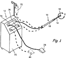
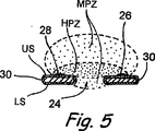
図1−2及び5は、本発明に従う組織を切断又は凝固するための機器の一実施形態の実施例を示す。これらの図面に示される機器10はその先端部に形成された脚部材16を有する長手部材14からなる。脚部材16は、図示されるように、第一の(又は右側の)脚部材部22と第二の(又は左側の)脚部材部20とに分岐される又は分けられる。第一及び第二の脚部材部22、20の間には開放領域24が存在する。脚部材16及び各脚部材部22、20は上面USおよび下面LSを有する。電気的かつ熱的に絶縁した被覆部30が脚部材16に形成される。この実施例において、絶縁被覆部30は上面US及び下面LSを含む脚部材16全体を覆う。しかしながら、機器10の幾らかの実施形態において、該絶縁被覆部30は脚部材16の下面LSのみ、又は脚部材部22、20の下面LSのみに配置され得ることは理解されるであろう。図5の断面に示されるように、脚部材16は、金属(例えば、医療用グレードのステンレス鋼)のような導電性コア材料から形成され得、被覆部30はコア材料の表面に配置されるコーティングから形成され得る。絶縁被覆部30を形成するコーティングはポリイミドのような誘電性ポリマーからなり、かつ単層浸漬コーティング、多層浸漬コーティング、塗装、粉体塗装(例えば、静電気)、蒸着等を含む(とはいえ、それらに限定されるものではない)任意の適切な手段により適用される。
1-2 and 5 show an example of one embodiment of an apparatus for cutting or coagulating tissue according to the present invention. The
少なくとも一つの電極は、脚部材60の上面USに配置される。この実施例にて示される機器10は二極であり、従って、第一の電極28は第一の脚部材部22の上面に配置されるとともに、第二の電極26は第二の脚部材部20の上面に配置される。電圧が加えられる際、これらの電極は脚部材60の上面USの上方、並びに第一及び第二の脚部材部22、20の間に存在する開放領域24の上方及び該開放領域24内の幾らかに、組織損傷熱帯域を形成する。図5に示されるように、電極26、28に電圧がかけられる場合、上述の上面USの上方の組織損傷熱帯域は、実際には高出力帯域HPZ及び中間出力帯域MPZを含み、いずれも組織を切断又は凝固するのに十分である。従って、効果的な組織損傷熱帯域は、高出力帯域HPZ及び中間出力帯域MPZの両方を含むであろう。
At least one electrode is disposed on the upper surface US of the leg member 60. The
図2に示されるように、機器10は長手部材14を貫通して延びるとともに孔34、36にて終了する一つ以上の内腔を選択的に含み得、それにより、流体又は物質が機器を介して注入及び/又は吸引され得る。幾らかの実施形態において、二つ(2)の内腔(図示しない)が含まれ得、これらの内腔は二つの独立した孔34、36にて終了し、それにより、機器10を介して同時に注入及び吸引が実施され得る。
As shown in FIG. 2, the
本発明の機器10は、図1に示される一実施例のようなシステム12の一部として使用され得る。このシステム12の基本的な構成部品は、電気外科的発生器76のような電流源、と、機器10において所望の量のエネルギを電極26、28に与えるために電気外科的発生器を制御する電気外科的フッドペダル80と、からなる。機器10が選択的な吸引用及び/又は注入用の内腔を含む場合、該システム12は、吸引ポンプモジュール74及び吸引フットペダル78及び/又は注入流体源72を付随的に含み得る。システムのこれらの構成部品は、独立しているか、又は図示されるように外科的ローラカート70に装着され得る。処置時のシステム機能の制御は、所望の量のエネルギを電極26、28に供給する電気外科的発生器を制御する電気外科的フットペダル80を移動することによって、そして選択的に吸引ポンプ74を制御するために吸引フットペダル78を移動することによって、及び/又は、重力供給圧を変更又は機器10の選択的な注入内腔を流れる注入流体の流速を変更することによって、達成され得る。幾らかの実施形態において、フットペダル78、80は、単一の多機能ユニットに組み込まれる。ピンチバルブ又はその他の手段もまた、機器10の注入流体の流れを制御するためにコンソール内に組み込まれ得る。選択肢として、システム12の基本的な制御機能の全ては容易に使用できるように単一のフットペダルに一体化され得る。
The
機器10は、標準的な電気外科的ハンドピース18に取り付け可能である、予め滅菌され、単回使用の使い捨て用プローブ若しくはチップとして供給され得る。代替的に、ハンドピース、カニューレ、カテーテル、内視鏡又はその他の装置に永久に取り付けられるか、又は一体的に形成され得る。
The
機器10及びシステム12は所望とされる種々の処置を実施するために使用可能である。
本発明の機器が組織を選択的に切断又は凝固するために使用される方法の実施例
1)後眼部における網膜過成長部の分離
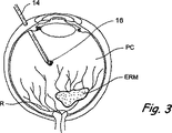
本発明の方法の一実施例は、ヒト又は動物検体の眼から網膜上膜を切除するために上述の機器を使用することである。この方法の幾らかの工程を、図3乃至4Aに示す。
Example 1 of a method in which the device of the present invention is used to selectively cut or coagulate tissue 1) Isolation of retinal overgrowth in the posterior segment of the eye. The use of the device described above to remove the epiretinal membrane from the eye. Some steps of this method are shown in FIGS. 3-4A.
この実施例において、図3乃至4Aを参照すると、網膜上膜ERMは、網膜Rの内境界膜と眼の後眼房PCを満たす硝子体皮質との間に形成された異常な、透明又は半透明な、コラーゲンを含有する膜である。この網膜上膜は別々の接着点APにて網膜Rに接着又は付着されている。従って、これらの接着点APのために、網膜上膜が接触すると、網膜上にて粘着摩擦が生じ、網膜がひずむか又は皺が生じ、患者の視力に支障を来たす。 In this example, referring to FIGS. 3-4A, the epiretinal membrane ERM is an abnormal, transparent or semi-hemiform formed between the inner limiting membrane of the retina R and the vitreous cortex that fills the posterior chamber PC of the eye. It is a transparent membrane containing collagen. The epiretinal membrane is adhered or attached to the retina R at different adhesion points AP. Therefore, when the epiretinal membrane comes into contact due to these adhesion points AP, adhesive friction occurs on the retina, and the retina is distorted or wrinkled, which impairs the visual acuity of the patient.
この実施例において網膜上膜ERMを切除するために、眼科外科医は最初に硝子体切除術を実施し、硝子体切除術用のカッターを使用して周知の技術に従って後眼房PCから硝子体を切除する。硝子体が切除されると、外科医は本発明の機器10を、図3に示されるように後眼房に挿入し、図4及び図4Aに示される位置まで該機器10を前進する。該位置において、接着点APは第一及び第二の脚部材部22、20の間にある開放領域24を貫通して延びており、網膜上膜ERMの残りは、脚部16の上面USの上方にあり、網膜Rは脚部16の下面LSの下方にある。機器10がそのように配置された状態にて、電極26、28が印加され、接着点APに配置された網膜上膜ERMの部分を切断又は破壊する一方で、脚部材部22、20及び絶縁カバー30は、該電極22、20の印加時に網膜Rを電気的又は熱的損傷から実質的に保護する。この手順は、配置された各接着点APに対して繰り返され、それにより網膜上膜ERMが網膜Rから分離され、裂傷、出血又は網膜の局所的な剥離さえも伴う該網膜の望ましくないけん引又は粘着摩擦を引き起こすこともなく、標準的な技術に従って、外科医が網膜上膜ERMの切除を進めることを可能にする。従って、この手順は、網膜の裂傷、出血又はその他の傷害の可能性を低減しつつ実施され得る。
To remove the epiretinal ERM in this example, the ophthalmic surgeon first performs a vitrectomy and uses the vitrectomy cutter to remove the vitreous from the posterior chamber PC according to well-known techniques. Resect. Once the vitreous is excised, the surgeon inserts the
図3乃至4Aは、網膜上膜を剥離する方法を特定して示しているが、組織が隣接する組織に実質的な損傷を与えることなく、該組織を選択的に切断又は凝固する多様な手順を実施するために本願のその他の部分に記載されているように、実質的に同様の様式にて使用され得ることは理解されよう。機器10が使用されるこれらのその他の方法の幾らかの実施例は、以下に記載された更なる実施例において記載されている。
FIGS. 3-4A illustrate a specific method of detaching the epiretinal membrane, but various procedures for selectively cutting or coagulating tissue without substantially damaging adjacent tissue. It will be understood that it can be used in a substantially similar manner as described elsewhere in this application to implement. Some examples of these other methods in which the
2)後眼部における網膜血管の選択的焼灼術
多くの場合糖尿病と関連されるある種の疾病の状態の結果として、網膜血管異常が起こる。糖尿病性網膜症は多くの場合、最初に網膜血管の弱化及び出血を伴う。後の段階において、新たな血管が多くの場合増殖し始めて硝子体内部にまで成長し、視界をあいまいにする。治療としては多くの場合、焦点のレーザ光凝固術を含み、該光凝固術においてはレーザが使用され、網膜を横切って指向するか若しくは分散される光凝固術の小さなスポットが形成される。本発明の機器10及び/又はシステム12は、隣接する網膜組織に対する熱的な損傷を制限しつつ、網膜或いは該網膜から延出する血管を選択的に凝固する効果的な手段を提供する。
2) Selective cauterization of retinal blood vessels in the posterior segment of the eye. Retinal vascular abnormalities occur as a result of certain disease states often associated with diabetes. Diabetic retinopathy is often initially accompanied by weakening of the retinal blood vessels and bleeding. At a later stage, new blood vessels often begin to grow and grow into the vitreous, obscuring vision. Treatment often includes focal laser photocoagulation, in which a laser is used to form a small spot of photocoagulation that is directed or dispersed across the retina. The
3)歯肉/口腔外科的切開
歯科の処置及び口腔外科の処置において、多くの場合、歯肉の切開を伴う。これらの切開は、多くの場合、歯、歯根、神経及びその他の敏感な構造体の付近にて実施される。加えて、歯肉組織は大いに血管が発達しており、切断は重大な出血を引き起こす。本発明の機器10及び/又はシステム12は、隣接する敏感な組織及び構造体を保護するとともに出血を低減しながら、歯肉組織を切断するための優れた手段を提供することができる。
3) Gingival / oral surgical incision In dentistry and oral surgery procedures, gingival incision is often accompanied. These incisions are often performed in the vicinity of teeth, roots, nerves and other sensitive structures. In addition, gingival tissue is highly vascularized, and amputation causes significant bleeding. The
4)皮膚科における処置
皮膚科における処置は、特殊の成長部の選択的な切除、下側の組織を保護するために損傷の深さを制御する必要性のある皮膚の切断を伴い、かつ出血の制御が必要とされる。本発明の機器10及び/又はシステム12は、そのような処置を実施するための手段を提供し、該処置に対して顕著な利点を提供するようにエネルギが加えられる。
4) Dermatology treatment Dermatology treatment involves selective excision of special growths, cuts of the skin that need to control the depth of damage to protect the underlying tissue, and bleeding Control is required. The
5)腫瘍又はその他の組織成長物の選択的な切除/除去
癌性の腫瘍及びその他の異常な組織成長物は、多くの場合、主要な器官又は敏感な組織に隣接して配置されているか或いは非常に密接な関係があることから、治療が困難又は手術不可能であるとみなされている。本発明の機器10及び/又はシステム12は、腫瘍の切除又は除去において使用されるエネルギをより良好に指向する手段を外科医に提供し、それによりそのような処置が、重要な器官又は敏感な組織付近においてもより良好に実施され得る。加えて、そのような処置は、たとえそれらが特に重要又は敏感な組織ではなくても、隣接する正常組織への損傷を軽減しながら実施され得、治癒に要する時間を低減するとともに局所における損傷を制限する。腫瘍又は肉茎性を有する幾らかの皮膚病巣のような非癌性の成長物は、機器10を用いて、該機器10を配置することにより除去され得る。
5) Selective excision / removal of tumors or other tissue growths Cancerous tumors and other abnormal tissue growths are often located adjacent to major organs or sensitive tissues, or Because of the close relationship, it is considered difficult to treat or inoperable. The
6)脳及び神経系の外科的処置
神経系の処置及び脳の手術は多くの場合、繊細な組織の切断及び/又は除去、或いは神経及び/又は脳の組織のような敏感な組織に非常に近接した出血性の部位の治療を包含する。これらの場合、本発明の機器10及び/又はシステム12は、そのような隣接した神経若しくは脳の組織への損傷を最小限に留めながら、そのような組織の切断及び/又は除去或いは出血部位の治療を容易にするという利点を提供する。
6) Brain and Nervous System Surgical Treatment Nervous system treatment and brain surgery are often very sensitive to sensitive tissue such as nerve and / or brain tissue. Includes treatment of adjacent bleeding sites. In these cases, the
7)声帯の手術
声帯は多くの場合異常な成長物(例えば、小結節)により影響を受け、該成長物は繊細な声帯への損傷を最小限に留めながら、慎重に除去しなければならない。本発明の機器10及び/又はシステム12は、隣接した声帯組織への損傷の発生を最小限に留めながら、これらの異常成長物を除去するための優れた手段を外科医に提供する。
7) Surgery of the vocal cords The vocal cords are often affected by abnormal growths (eg, nodules) that must be carefully removed with minimal damage to the delicate vocal cords. The
8)心臓手術
本発明の機器10及び/又はシステム12は、心膜及び心内膜若しくはその他の心臓組織を含む心臓の膜組織構造体を切断するための効果的な手段を提供しながらも、心臓若しくはその他の構造体(例えば、心筋、冠状動脈若しくは心臓の血管、腱索(tenconous chord)、乳頭筋、心臓弁、小柱、心臓の結節組織、冠静脈血洞、隔膜若しくはその他の正常な心臓組織)を灌流させる該膜組織構造体の下方に位置する心筋及び/又は重要な脈管構造体を保護する。カテーテルベースの、或いは最小限の侵襲性である本発明の機器10及び/又はシステム12の実施は、また、選択的な切除(例えば、催不整脈経路若しくは組織を切除する)及び組織若しくは人工の弁処置、弁形成術若しくはアニュロプラスティー(anuloplasty)処置等において有利である。
8) Cardiac Surgery While the
8)肝臓の切開
肝臓における外科的処置は、複雑な配置にて肝組織を交差するより大きな血管構造体に対する出血を制御し、かつ該構造体への損傷を最小限に留めながら肝臓組織を切断することを多くの場合必要とする。本発明の機器10及び/又はシステム12は、肝組織を介する切断時における出血を制御しながら、隣接する血管及び組織への損傷を最小限に留める優れた様式を外科医に提供する。
8) Liver incision Surgical procedures in the liver control bleeding to larger vascular structures that intersect the liver tissue in a complex arrangement and cut the liver tissue while minimizing damage to the structure. You often need to do it. The
9)耳、鼻及び喉(ENT)の外科的処置
ENTの外科的処置は、多くの場合、隣接する敏感な構造体及び組織付近にて、該組織を切断する/凝固するために、微小に制限された経路(例えば、洞)において作業することを含む。本発明の機器10及び/又はシステム12は、限られた手術空間であるために必然的に幾何学的に非常に近接している隣接組織への損傷を選択的に回避しながらも、非常に制限された空間において手術を行う手段をENTの外科医に提供する。
9) Ear, Nose and Throat (ENT) Surgical Procedures ENT surgical procedures are often microscopically performed to cut / coagulate the tissue near adjacent sensitive structures and tissues. Including working in a restricted path (eg, a sinus). The
10)関節鏡視下手術
関節鏡視下手術は多くの場合、湿性領域の環境において組織を切断することを含む。隣接する構造体(例えば、骨)への損傷が最小限に留められることが容易に完治するには望ましい該隣接する構造体から組織(軟骨、腱など)を選択的に切断ことが多くの場合望ましい。また、これらの処置において、出血は視界をあいまいにする。従って、本発明の機器10及び/又はシステム12は、そのような処置に影響を与える優れた手段を、関節鏡視下手術を実施する外科医に提供する。
10) Arthroscopic surgery Arthroscopic surgery often involves cutting tissue in a wet area environment. Often, selective cutting of tissue (cartilage, tendon, etc.) from an adjacent structure is desirable to facilitate complete healing with minimal damage to the adjacent structure (eg, bone). desirable. In these procedures, bleeding can also obscure vision. Accordingly, the
11)結腸鏡検査及びその他の口腔若しくは消化器官の処置
治療若しくは診断(例えば、バイオプシー)の目的にて胃腸器官又は消化管から腫瘍、ポリープ及び/又はその他の成長物を除去することは、好ましくない出血及び/又は例えば腸せん孔のような隣接する組織への予想外の損傷を引き起こす。本発明の機器10及び/又はシステム12は、実質的な出血、消化管のせん孔、又は消化管壁へのその他の損傷を引き起こすことなく、消化管(例えば、直腸、大腸、小腸、十二指腸、胃、食道、中咽頭、舌又は口腔内洞)壁から腫瘍、ポリープ及び/又はその他の成長物を切断及び/又は除去するために、及び/又はバイオプシーサンプルを回収するために使用され得る。そのような処置において、機器10は前進され得る。
11) Colonoscopy and other oral or digestive organ treatments It is not desirable to remove tumors, polyps and / or other growths from the gastrointestinal tract or gastrointestinal tract for therapeutic or diagnostic (eg, biopsy) purposes. Causes hemorrhage and / or unexpected damage to adjacent tissues such as, for example, intestinal perforations. The
本発明はある実施形態及び実施例に関して上述のように記載されているが、そのような実施形態及び実施例は非限定的なものであり、本発明の全ての実施形態及び実施例を定義することを意図していないことは理解されよう。実際に、当業者は本発明の意図された精神及び範囲から逸脱することなく上述の実施形態及び実施例に対して種々の変更がなされること、そして、そのような変更の全てが以下に添付された請求の範囲内含まれていることが意図されていることを理解するであろう。 Although the invention has been described above with respect to certain embodiments and examples, such embodiments and examples are non-limiting and define all embodiments and examples of the invention. It will be understood that this is not intended. Indeed, those skilled in the art will recognize that various modifications can be made to the above-described embodiments and examples without departing from the intended spirit and scope of the present invention, and all such modifications are appended below. It will be understood that it is intended to be included within the scope of the appended claims.
Claims (19)
先端部を有する長手部材と、
前記長手部材の先端部から角度をなして、かつ同長手部材の先端部の一方の側に延出する分岐した脚部材であって、その先端側が右側脚部材部と左側脚部材部とに分岐している脚部材と、を含み、
前記右側脚部材部及び前記左側脚部材部の各々は、前記長手部材と対面する第1の面と、前記第1の面と相対向する第2の面であって前記長手部材と対面していない第2の面と、をそれぞれ備え、
前記右側脚部材部の内側端と前記左側脚部材部の内側端とはその間に開放領域を備えた状態にて互いに対して並置されており、
前記右側脚部材部及び前記左側脚部材部の各々の少なくとも前記第2の面には電気的かつ熱的な絶縁被覆部が設けられており、
前記右側脚部材部及び前記左側脚部材部の各々の前記第1の面には電極が設けられており、
前記電極は、前記右側脚部材部及び前記左側脚部材部の各々の前記第2の面の下方に配置されている組織を熱切断及び熱凝固の少なくとも一方を引き起こすことなく、前記開放領域の上側の位置にて組織を熱切断するか、又は熱凝固するかの少なくとも一方を行うために、電圧を印加可能である、機器。A device for cutting or coagulating tissue, the device comprising:
A longitudinal member having a tip;
Wherein an angle from the distal end of the longitudinal member, and a branched leg members extending to one side of the distal end portion of the longitudinal member, and the tip end right side leg member portion and the left side leg member portion anda leg member branches into,
Each of the right leg member portion and the left leg member portion is a first surface facing the longitudinal member, and a second surface facing the first surface and facing the longitudinal member. Each having a second surface,
Wherein the inner end of the right leg member portions and the inner end of the left leg member portions are juxtaposed with respect to each other in a state with an open area therebetween,
At least the second surface of each of the right leg member portion and the left leg member portion is provided with an electrically and thermally insulating coating portion,
The first surface of each of the right leg member portion and the left leg member portion is provided with an electrode,
The electrode, the right leg member portion and the left leg member portions each of said tissue being disposed below the second surface of without causing at least one of the thermal cutting and thermal coagulation, pre KiHiraki release region A device to which a voltage can be applied to at least one of thermally cutting and / or heat coagulating the tissue at a position above.
Applications Claiming Priority (3)
| Application Number | Priority Date | Filing Date | Title |
|---|---|---|---|
| US47725803P | 2003-06-10 | 2003-06-10 | |
| US60/477,258 | 2003-06-10 | ||
| PCT/US2004/018482 WO2004110259A2 (en) | 2003-06-10 | 2004-06-10 | Electrosurgical devices and methods for selective cutting of tissue |
Publications (3)
| Publication Number | Publication Date |
|---|---|
| JP2007500582A JP2007500582A (en) | 2007-01-18 |
| JP2007500582A5 JP2007500582A5 (en) | 2007-08-02 |
| JP4704344B2 true JP4704344B2 (en) | 2011-06-15 |
Family
ID=41264232
Family Applications (1)
| Application Number | Title | Priority Date | Filing Date |
|---|---|---|---|
| JP2006533689A Active JP4704344B2 (en) | 2003-06-10 | 2004-06-10 | Electrosurgical instrument for selectively cutting tissue and system including the same |
Country Status (7)
| Country | Link |
|---|---|
| US (1) | US7842034B2 (en) |
| EP (1) | EP1633267B1 (en) |
| JP (1) | JP4704344B2 (en) |
| CA (1) | CA2528056C (en) |
| ES (1) | ES2544478T3 (en) |
| MX (1) | MXPA05013311A (en) |
| WO (1) | WO2004110259A2 (en) |
Families Citing this family (32)
| Publication number | Priority date | Publication date | Assignee | Title |
|---|---|---|---|---|
| US7811282B2 (en) | 2000-03-06 | 2010-10-12 | Salient Surgical Technologies, Inc. | Fluid-assisted electrosurgical devices, electrosurgical unit with pump and methods of use thereof |
| US6558385B1 (en) * | 2000-09-22 | 2003-05-06 | Tissuelink Medical, Inc. | Fluid-assisted medical device |
| US6689131B2 (en) | 2001-03-08 | 2004-02-10 | Tissuelink Medical, Inc. | Electrosurgical device having a tissue reduction sensor |
| US8048070B2 (en) * | 2000-03-06 | 2011-11-01 | Salient Surgical Technologies, Inc. | Fluid-assisted medical devices, systems and methods |
| JP2004500207A (en) * | 2000-03-06 | 2004-01-08 | ティシューリンク・メディカル・インコーポレーテッド | Fluid delivery system and electrosurgical instrument controller |
| US7311708B2 (en) * | 2001-12-12 | 2007-12-25 | Tissuelink Medical, Inc. | Fluid-assisted medical devices, systems and methods |
| US8475455B2 (en) | 2002-10-29 | 2013-07-02 | Medtronic Advanced Energy Llc | Fluid-assisted electrosurgical scissors and methods |
| US20060241580A1 (en) | 2003-06-10 | 2006-10-26 | Neomedix Corporation | Device and methods useable for treatment of glaucoma and other surgical procedures |
| US7959641B2 (en) | 2003-06-10 | 2011-06-14 | Neomedix Corporation | Tubular cutter device and methods for cutting and removing strips of tissue from the body of a patient |
| US7727232B1 (en) | 2004-02-04 | 2010-06-01 | Salient Surgical Technologies, Inc. | Fluid-assisted medical devices and methods |
| US7481225B2 (en) * | 2005-01-26 | 2009-01-27 | Ethicon Endo-Surgery, Inc. | Medical instrument including an end effector having a medical-treatment electrode |
| US8641701B2 (en) * | 2007-03-06 | 2014-02-04 | Kyoto University | Probe type device for removing living body tissue |
| US7850679B2 (en) * | 2007-09-12 | 2010-12-14 | Drake Daniel H | Mitral hook |
| US20090287233A1 (en) * | 2008-05-15 | 2009-11-19 | Huculak John C | Small Gauge Mechanical Tissue Cutter/Aspirator Probe For Glaucoma Surgery |
| US9125720B2 (en) | 2008-10-13 | 2015-09-08 | Alcon Research, Ltd. | Capsularhexis device with flexible heating element |
| US8137344B2 (en) | 2008-12-10 | 2012-03-20 | Alcon Research, Ltd. | Flexible, automated capsulorhexis device |
| US8157797B2 (en) | 2009-01-12 | 2012-04-17 | Alcon Research, Ltd. | Capsularhexis device with retractable bipolar electrodes |
| US8814854B2 (en) * | 2009-06-03 | 2014-08-26 | Alcon Research, Ltd. | Capsulotomy repair device and method for capsulotomy repair |
| US20100312252A1 (en) * | 2009-06-03 | 2010-12-09 | Guangyao Jia | Capsularhexis device with flexible heating element having an angled transitional neck |
| US20110202049A1 (en) * | 2010-02-18 | 2011-08-18 | Alcon Research, Ltd. | Small Gauge Ablation Probe For Glaucoma Surgery |
| US9241755B2 (en) | 2010-05-11 | 2016-01-26 | Alcon Research, Ltd. | Capsule polishing device and method for capsule polishing |
| US9149388B2 (en) | 2010-09-29 | 2015-10-06 | Alcon Research, Ltd. | Attenuated RF power for automated capsulorhexis |
| EP2841159B1 (en) * | 2012-04-24 | 2017-07-26 | Light Instruments Ltd. | An electromagnetic shield for a dental laser hand piece |
| RU2495631C1 (en) * | 2012-06-07 | 2013-10-20 | Государственное бюджетное учреждение здравоохранения Московской области "Московский областной научно-исследовательский клинический институт им. М.Ф. Владимирского" (ГБУЗ МО МОНИКИ) | Method of treating aberrant pancreas which is located in stomach |
| WO2014055981A1 (en) * | 2012-10-05 | 2014-04-10 | Board Of Regents, The University Of Texas System | System and method for scoring the left ventricular endocardium to increase left ventricular compliance |
| USD707818S1 (en) | 2013-03-05 | 2014-06-24 | Alcon Research Ltd. | Capsulorhexis handpiece |
| US10433861B2 (en) | 2013-08-27 | 2019-10-08 | Board Of Regents Of The University Of Texas System | System and method for cutting trabeculae carneae of the left ventricle to increase LV compliance |
| USD737438S1 (en) | 2014-03-04 | 2015-08-25 | Novartis Ag | Capsulorhexis handpiece |
| KR102573821B1 (en) | 2017-02-16 | 2023-08-31 | 마이크로서지컬 테크놀로지, 인코퍼레이티드 | Apparatus, system and method for minimally invasive glaucoma surgery |
| US11786296B2 (en) | 2019-02-15 | 2023-10-17 | Accularent, Inc. | Instrument for endoscopic posterior nasal nerve ablation |
| US11534235B2 (en) | 2019-04-04 | 2022-12-27 | Acclarent, Inc. | Needle instrument for posterior nasal neurectomy ablation |
| US11259961B2 (en) | 2019-07-22 | 2022-03-01 | Iantrek, Inc. | Methods and devices for increasing aqueous drainage of the eye |
Citations (6)
| Publication number | Priority date | Publication date | Assignee | Title |
|---|---|---|---|---|
| US5269782A (en) * | 1991-04-22 | 1993-12-14 | Select Medizin-Technik Hermann Sutter Gmbh | Bipolar medical coagulation and cauterizing instrument |
| JPH10510745A (en) * | 1995-06-07 | 1998-10-20 | アースロケア コーポレイション | System and method for electrosurgical resection and ablation |
| JP2002503508A (en) * | 1998-02-20 | 2002-02-05 | アースロケア コーポレイション | System and method for electrosurgical spine surgery |
| JP2002507924A (en) * | 1997-07-03 | 2002-03-12 | ネオサーミア コーポレイション | Method and apparatus for therapeutic ablation of a volume of biological tissue |
| WO2002089686A1 (en) * | 2001-05-10 | 2002-11-14 | Rita Medical Systems, Inc. | Rf tissue ablation apparatus and method |
| JP2003504108A (en) * | 1999-07-07 | 2003-02-04 | ユーエイビー・リサーチ・ファウンデイション | Ablation instrument |
Family Cites Families (8)
| Publication number | Priority date | Publication date | Assignee | Title |
|---|---|---|---|---|
| US5681282A (en) * | 1992-01-07 | 1997-10-28 | Arthrocare Corporation | Methods and apparatus for ablation of luminal tissues |
| US5445637A (en) * | 1993-12-06 | 1995-08-29 | American Cyanamid Company | Method and apparatus for preventing posterior capsular opacification |
| US5458596A (en) * | 1994-05-06 | 1995-10-17 | Dorsal Orthopedic Corporation | Method and apparatus for controlled contraction of soft tissue |
| US5916213A (en) * | 1997-02-04 | 1999-06-29 | Medtronic, Inc. | Systems and methods for tissue mapping and ablation |
| US6432104B1 (en) * | 1998-04-15 | 2002-08-13 | Scimed Life Systems, Inc. | Electro-cautery catherer |
| US6558382B2 (en) * | 2000-04-27 | 2003-05-06 | Medtronic, Inc. | Suction stabilized epicardial ablation devices |
| IL156831A0 (en) | 2001-01-18 | 2004-02-08 | Univ California | Minimally invasive glaucoma surgical instrument and method |
| US7244256B2 (en) * | 2004-06-10 | 2007-07-17 | Linvatec Corporation | Electrosurgical device with adhesive-free insulating piece and method of making same |
-
2004
- 2004-06-10 WO PCT/US2004/018482 patent/WO2004110259A2/en active Application Filing
- 2004-06-10 US US10/560,265 patent/US7842034B2/en active Active
- 2004-06-10 EP EP20040754919 patent/EP1633267B1/en active Active
- 2004-06-10 JP JP2006533689A patent/JP4704344B2/en active Active
- 2004-06-10 ES ES04754919.1T patent/ES2544478T3/en active Active
- 2004-06-10 CA CA2528056A patent/CA2528056C/en active Active
- 2004-06-10 MX MXPA05013311A patent/MXPA05013311A/en active IP Right Grant
Patent Citations (6)
| Publication number | Priority date | Publication date | Assignee | Title |
|---|---|---|---|---|
| US5269782A (en) * | 1991-04-22 | 1993-12-14 | Select Medizin-Technik Hermann Sutter Gmbh | Bipolar medical coagulation and cauterizing instrument |
| JPH10510745A (en) * | 1995-06-07 | 1998-10-20 | アースロケア コーポレイション | System and method for electrosurgical resection and ablation |
| JP2002507924A (en) * | 1997-07-03 | 2002-03-12 | ネオサーミア コーポレイション | Method and apparatus for therapeutic ablation of a volume of biological tissue |
| JP2002503508A (en) * | 1998-02-20 | 2002-02-05 | アースロケア コーポレイション | System and method for electrosurgical spine surgery |
| JP2003504108A (en) * | 1999-07-07 | 2003-02-04 | ユーエイビー・リサーチ・ファウンデイション | Ablation instrument |
| WO2002089686A1 (en) * | 2001-05-10 | 2002-11-14 | Rita Medical Systems, Inc. | Rf tissue ablation apparatus and method |
Also Published As
| Publication number | Publication date |
|---|---|
| US20070010812A1 (en) | 2007-01-11 |
| ES2544478T3 (en) | 2015-08-31 |
| EP1633267A2 (en) | 2006-03-15 |
| JP2007500582A (en) | 2007-01-18 |
| CA2528056A1 (en) | 2004-12-23 |
| CA2528056C (en) | 2014-07-29 |
| US7842034B2 (en) | 2010-11-30 |
| EP1633267B1 (en) | 2015-05-06 |
| WO2004110259A2 (en) | 2004-12-23 |
| MXPA05013311A (en) | 2006-08-18 |
| WO2004110259A3 (en) | 2005-04-21 |
| EP1633267A4 (en) | 2008-08-06 |
Similar Documents
| Publication | Publication Date | Title |
|---|---|---|
| JP4704344B2 (en) | Electrosurgical instrument for selectively cutting tissue and system including the same | |
| US20230380889A1 (en) | Debridement device and method | |
| JP6110343B2 (en) | System and method for electrosurgical treatment of the head and neck | |
| JP5320065B2 (en) | Suction type coagulation probe | |
| JP4223289B2 (en) | Endoscopic ablation system with improved electrode geometry | |
| US7717913B2 (en) | RF cauterization and ultrasonic ablation instrument with multi-hole collar and electrode mounting sleeve | |
| CA2273925C (en) | Mechanical and electrical endoscopic surgical instrument | |
| US7223267B2 (en) | Ultrasonic probe with detachable slidable cauterization forceps | |
| US20130178845A1 (en) | Devices and methods for bipolar and monopolar procedures | |
| US20020177847A1 (en) | Endoscopic ablation system with flexible coupling | |
| AU2002254494A1 (en) | Endoscopic ablation system with improved electrode geometry | |
| JP2002509756A (en) | Method and apparatus for removing substances or calcified deposits | |
| JP2016512090A (en) | Apparatus for tissue separation and related uses | |
| AU2002309525B2 (en) | Endoscopic ablation system with sealed sheath | |
| AU2002309525A1 (en) | Endoscopic ablation system with sealed sheath |
Legal Events
| Date | Code | Title | Description |
|---|---|---|---|
| A521 | Request for written amendment filed |
Free format text: JAPANESE INTERMEDIATE CODE: A523 Effective date: 20070607 |
|
| A621 | Written request for application examination |
Free format text: JAPANESE INTERMEDIATE CODE: A621 Effective date: 20070607 |
|
| A977 | Report on retrieval |
Free format text: JAPANESE INTERMEDIATE CODE: A971007 Effective date: 20091126 |
|
| A131 | Notification of reasons for refusal |
Free format text: JAPANESE INTERMEDIATE CODE: A131 Effective date: 20091201 |
|
| A601 | Written request for extension of time |
Free format text: JAPANESE INTERMEDIATE CODE: A601 Effective date: 20100301 |
|
| A602 | Written permission of extension of time |
Free format text: JAPANESE INTERMEDIATE CODE: A602 Effective date: 20100308 |
|
| A521 | Request for written amendment filed |
Free format text: JAPANESE INTERMEDIATE CODE: A523 Effective date: 20100601 |
|
| A131 | Notification of reasons for refusal |
Free format text: JAPANESE INTERMEDIATE CODE: A131 Effective date: 20100713 |
|
| A601 | Written request for extension of time |
Free format text: JAPANESE INTERMEDIATE CODE: A601 Effective date: 20101013 |
|
| A602 | Written permission of extension of time |
Free format text: JAPANESE INTERMEDIATE CODE: A602 Effective date: 20101020 |
|
| A521 | Request for written amendment filed |
Free format text: JAPANESE INTERMEDIATE CODE: A523 Effective date: 20110113 |
|
| TRDD | Decision of grant or rejection written | ||
| A01 | Written decision to grant a patent or to grant a registration (utility model) |
Free format text: JAPANESE INTERMEDIATE CODE: A01 Effective date: 20110208 |
|
| A61 | First payment of annual fees (during grant procedure) |
Free format text: JAPANESE INTERMEDIATE CODE: A61 Effective date: 20110309 |
|
| R150 | Certificate of patent or registration of utility model |
Ref document number: 4704344 Country of ref document: JP Free format text: JAPANESE INTERMEDIATE CODE: R150 |
|
| R250 | Receipt of annual fees |
Free format text: JAPANESE INTERMEDIATE CODE: R250 |
|
| R250 | Receipt of annual fees |
Free format text: JAPANESE INTERMEDIATE CODE: R250 |
|
| R250 | Receipt of annual fees |
Free format text: JAPANESE INTERMEDIATE CODE: R250 |
|
| R250 | Receipt of annual fees |
Free format text: JAPANESE INTERMEDIATE CODE: R250 |
|
| R250 | Receipt of annual fees |
Free format text: JAPANESE INTERMEDIATE CODE: R250 |
|
| R250 | Receipt of annual fees |
Free format text: JAPANESE INTERMEDIATE CODE: R250 |
|
| S111 | Request for change of ownership or part of ownership |
Free format text: JAPANESE INTERMEDIATE CODE: R313113 |
|
| S631 | Written request for registration of reclamation of domicile |
Free format text: JAPANESE INTERMEDIATE CODE: R313631 |
|
| R350 | Written notification of registration of transfer |
Free format text: JAPANESE INTERMEDIATE CODE: R350 |
|
| R250 | Receipt of annual fees |
Free format text: JAPANESE INTERMEDIATE CODE: R250 |
|
| R250 | Receipt of annual fees |
Free format text: JAPANESE INTERMEDIATE CODE: R250 |