JP4704207B2 - Diopter correction finder aids - Google Patents
Diopter correction finder aids Download PDFInfo
- Publication number
- JP4704207B2 JP4704207B2 JP2005367240A JP2005367240A JP4704207B2 JP 4704207 B2 JP4704207 B2 JP 4704207B2 JP 2005367240 A JP2005367240 A JP 2005367240A JP 2005367240 A JP2005367240 A JP 2005367240A JP 4704207 B2 JP4704207 B2 JP 4704207B2
- Authority
- JP
- Japan
- Prior art keywords
- click
- angle
- rotary seat
- diopter
- finder
- Prior art date
- Legal status (The legal status is an assumption and is not a legal conclusion. Google has not performed a legal analysis and makes no representation as to the accuracy of the status listed.)
- Active
Links
Images


Description
本発明は、望遠鏡、双眼鏡、顕微鏡、カメラ、測量器、その他の各種光学機器の接眼部に接続して使用する視度補正ファインダ補助具に関し、特に乱視眼用の視度補正ファインダ補助具に関する。 The present invention relates to a diopter correction finder auxiliary tool used by being connected to an eyepiece of a telescope, binoculars, a microscope, a camera, a surveying instrument, and other various optical devices, and more particularly to a diopter correction finder auxiliary tool for astigmatic eyes. .
従来から、望遠鏡、双眼鏡、顕微鏡、カメラ、測量器、その他の各種光学機器における近視眼や遠視眼のための視度補正用具が存在する。たとえば実開平5−41271号公報(特許文献1)には、光学機器の鏡胴開口部に適用する近視眼あるいは遠視眼までの視度調整を可能にするファインダとして、ヘリカル状の溝により対眼レンズを光軸方向に移動調整するファインダが開示されている。
前記のように、各種光学機器用のファインダ部分に近視眼または遠視眼用レンズを取り付ける視度補正器具は存在するが、乱視眼に有効な視度補正具はない。乱視眼においては、2種類の度数の違う近視が一つの眼に存在しているため、眼内合焦位置が角膜及び水晶体などの強主経線方向とそれに直角を成す弱主経線方向で違うといった状況が起きている。したがって、乱視補正は各主経線による前焦線及び後焦線に応じて各々が一点と成るように合焦させる必要がある。 As described above, there are diopter correction instruments for attaching a lens for a myopic eye or a hyperopic eye to a finder portion for various optical devices, but there is no diopter correction tool effective for astigmatic eyes. In an astigmatic eye, two types of myopia with different powers exist in one eye, so the intraocular focus position differs between the strong main meridian direction of the cornea and the lens and the weak main meridian direction perpendicular to it. The situation is happening. Therefore, the astigmatism correction needs to be focused so that each point becomes one point according to the front focal line and the rear focal line of each main meridian.
本発明は、各種の光学機器にそのままあるいは接続アダプターを使用して簡単に取り付けられる乱視眼用の視度補正ファインダ補助具を提供することを目的とする。
また、本発明の他の目的は、光学機器使用者の近視・遠視および乱視眼程度に応じて度数の違うレンズを容易に取替えセットでき、さらにカメラ等の光学機器においてファインダの覗き姿勢が、横位置、縦位置と頻繁に変わる場合であっても、一旦設定したレンズ合焦角度を容易に追随しそのレンズ合焦角度を保つことができる視度補正ファインダ補助具を提供することである。
An object of the present invention is to provide a diopter correction finder auxiliary tool for astigmatic eyes that can be easily attached to various optical devices as they are or using a connection adapter.
Another object of the present invention is to easily change and set lenses having different powers according to the degree of myopia, hyperopia, and astigmatism of the optical device user. To provide a diopter correction finder auxiliary tool that can easily follow a lens focusing angle once set and can maintain the lens focusing angle even when the position and the vertical position frequently change.
本発明の請求項1に記載の視度補正ファインダ補助具は、乱視補正レンズスリーブ(1)と、角度調整回転座(10)と、クリック回転座(20)と、が接眼位置から順にそれぞれ回動自在に係合された視度補正ファインダ補助具であって、該乱視補正レンズスリーブ(1)は、乱視補正レンズ(6)を内部に固定装着し、該乱視補正レンズスリーブ(1)の外周に設けられた角度半固定用環溝(11)に挿入される角度半固定用ボルト(8)によって、接眼側と反対側の角度調整回転座(10)と半固定状態に係合され、該角度調整回転座(10)は、その外周に螺着したクリック停止用ボルト(12)によって該クリック回転座(20)のクリック停止環溝(21)に角度90°毎にクリック停止できるように係合されることを特徴とする。
The diopter correction finder assisting tool according to
請求項2に記載の視度補正ファインダ補助具は、請求項1において、前記角度調整回転座(10)の開口部外周に螺着した固定ボルト(13)の締め付けにより係合するクリック回転座(20)を固定することを特徴とする。
The diopter correction finder auxiliary tool according to
請求項3に記載の視度補正ファインダ補助具は、請求項1又は2において、前記クリック回転座(20)の開口部外周に、光学機器接続用のネジ部(22)により視度補正アイピース(30)をさらに付加したことを特徴とする。
The diopter correction finder auxiliary tool according to
本発明によれば、各種光学機器における観察者の特に乱視眼の矯正や、近視眼または遠視眼の視度補正ができる。
また、ファインダの覗き姿勢を90°変化させた場合でも、容易に適正乱視矯正角度を追随して維持できる。
さらに、本発明の視度補正ファインダ補助具は、構造が簡単であり、各種光学機器に直接、あるいは接続アダプターの使用により容易に取り付けることができ、使い勝手がよい。
According to the present invention, it is possible to correct an astigmatism eye of an observer, and a diopter correction of a myopic eye or a hyperopic eye in various optical devices.
Further, even when the finder peeping posture is changed by 90 °, the proper astigmatism correction angle can be easily followed and maintained.
Furthermore, the diopter correction finder auxiliary tool of the present invention has a simple structure, can be easily attached to various optical devices directly or by using a connection adapter, and is easy to use.
<実施の形態1>
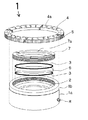
図1は、本発明の実施の形態1にかかる視度補正ファインダ補助具を示す組立て断面図である。
図1に示すように、実施の形態1の視度補正ファインダ補助具Aは、図1の上方の接眼位置から順に、乱視補正レンズスリーブ1、角度調整回転座10、クリック回転座20をそれぞれ回動自在に係合して構成される。
<
FIG. 1 is an assembled sectional view showing a diopter correction finder auxiliary tool according to a first embodiment of the present invention.
As shown in FIG. 1, the diopter correction finder auxiliary tool A of
乱視補正レンズスリーブ1は、円筒状の乱視補正レンズスリーブ胴1aを備え、その接眼側開口部周縁に回転角度表示リング4がリング固定用ボルト5により固定される。
また、乱視補正レンズスリーブ胴1aの内部には、乱視補正レンズ6がスペーサーリング3を介してレンズ固定リング7により固定装着されている。
乱視補正レンズスリーブ1は、この乱視補正レンズスリーブ胴1aの他端開口部に螺着した角度半固定用ボルト8により、その下方の角度調整回転座10に半固定状態に係合される。
The astigmatism
An
The astigmatism
すなわち、角度調整回転座10の接眼側開口部外周には、角度半固定用環溝11が設けられており、前記乱視補正レンズスリーブ胴1aの角度半固定用ボルト8の先端が、この角度半固定用環溝11に挿入され、乱視補正レンズスリーブ1とその下方の角度調整回転座10とが半固定状態に係合されるのである。
That is, an angle
また、角度調整回転座10は、その外周に螺着したクリック停止用ボルト12によって該クリック回転座20のクリック停止環溝21に角度90°毎にクリック停止できるように係合されている。
さらに、クリック回転座20は、必要に応じて角度調整回転座10をクリック回転座20に対して回転しないように固定することができる。すなわち、角度調整回転座10は、接眼側と反対側の他端開口部近傍に設けた固定ボルト13(図1では直径方向に対向配置した2本を示す)をネジ込み締め付けてクリック回転座20に固定される。
さらに、クリック回転座20の他端開口部近傍外周には接続ネジ部22が設けられ各種光学機器の接眼部(図示せず)にネジ込み接続できるようになっている。
The angle adjusting
Furthermore, the
Further, a
次に、本発明の実施の形態1の視度補正ファインダ補助具Aの主要構成部品について、図2〜図8を用いてより詳しく説明する。
図2は、乱視補正レンズスリーブ1の構成部品の組み立て構造を説明する斜視図である。各構成部品は、光軸方向(図面では縦方向)に分離して表示してある。
Next, main components of the diopter correction finder auxiliary tool A according to the first embodiment of the present invention will be described in more detail with reference to FIGS.
FIG. 2 is a perspective view for explaining an assembly structure of components of the astigmatism
図2に示すように、乱視補正レンズスリーブ胴1aの接眼側には、その外径を少し小さくしたリングセット段部1bが形成されており、リングセット段部1bに回転角度表示リング4を挿入して、回転角度表示リング4の側面からリング固定用ボルト5をネジ締めしてリングセット段部1bに固定できるようになっている。回転角度表示リング4の上面には、適宜調節した回転角度が把握できるように、等間隔に角度目盛4aが描かれている。
As shown in FIG. 2, a ring set
乱視補正レンズスリーブ胴1aには、内径をわずか大きくした段状のレンズ支持台2が設けられ、スペーサーリング3を介して乱視補正レンズ6をセットして、上方開口部からレンズ固定リング7をネジ込むことにより、乱視補正レンズ6を内部に固定できるようになっている。レンズ固定リング7の上部には、直径方向に4本の溝である着脱用工具溝7a設けられ、この工具溝7aにレンズ固定リング7を回転させる工具を当接させ、着脱してレンズ交換ができる。
The astigmatism correction lens sleeve body 1a is provided with a
また、乱視補正レンズスリーブ胴1aの下部にあるネジ穴に螺着する角度半固定用ボルト8は、図4(a)に示すような内部構造となっている。すなわち、角度半固定用ボルト8の内部には空洞8dが設けられ、空洞8dには、スプリング8aおよび押圧心棒8bが内挿されている。
押圧心棒8bの先端にはマイナスドライバーの刃のような形状をした半固定刃8cが取り付けられ、角度調整回転座10外周の角度半固定用環溝11底部の微細溝14へスプリング弾力により付勢されている。
このように、半固定刃8cの先端が微細溝14の凹部に喰いこみ、角度調整回転座10の回転に対し、軽い回転抵抗が生じるので、乱視補正レンズスリーブ胴1aは角度調整回転座10に対して360°回転は出来るが一旦停止すると人手により軽い操作をしない限り振動などによる滑りで回転することはない。
なお、ここで、半固定とは、角度半固定用ボルト8の締め付けを調整(スプリング8aの付勢力を加減)して、乱視補正レンズスリーブ1を任意の角度位置で角度調整回転座10に固定する機構をいう。
The
A
In this way, the tip of the
Here, semi-fixed means adjusting the tightening of the angle semi-fixing bolt 8 (adjusting the biasing force of the
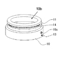
図3は、角度調整回転座10の概略構造を説明する斜視図である。角度調整回転座10の上部開口部10bの近くの外周には、図2で示した乱視補正レンズスリーブ胴体1aの角度半固定用ボルト8を挿入して係合させるための角度半固定用環溝11が、周状に設けられているとともに、その底部には縦方向に複数の微細溝14が設けられている。
FIG. 3 is a perspective view illustrating a schematic structure of the angle adjusting
角度調整回転座10の下部の外周にはクリック停止用ボルト12をネジ込むネジ穴10aが設けられている。
図4(b)は、ネジ穴10a(図3に示す)にネジ込むクリック停止用ボルト12の断面構造を示したものである。クリック停止用ボルト12の内部も前述した角度半固定用ボルト8と同様、空洞12dが設けられ、空洞12dには、スプリング12aおよび押圧心棒12bが内挿されている。押圧心棒12bの先端には、クリックボール12cが取り付けられ、図5に示すクリック回転座20外周のクリック停止環溝21の溝底部へスプリング弾力により付勢されている。クリック停止環溝21の溝底部には、図5において直角に交叉するX方向、Y方向位置に、角度90°間隔で4つのクリック穴24が設けられている。
A
FIG. 4B shows a cross-sectional structure of the
角度調整回転座10を回転させて、クリックボール12cがクリック穴24位置に合致したときクリックボール12cが穴に落とし込まれ、角度調整回転座10の回転はスプリング12aの付勢力により、その位置で一時的に停止させられる。すなわち、角度調整回転座10は90°回転するごとに、一時停止するので、回転角度の90°変化を容易に感じ取ることができる。クリックボール12cが穴に落とし込まれているので、一旦停止した角度調整回転座10が振動などで自然に再回転するのを防止することができる。
When the angle adjusting
図5は、クリック回転座20の構造を説明する斜視図である。クリック回転座20の上部開口部20aの近くの外周には、角度調整回転座10のクリック停止用ボルト12を挿入して係合させるためのクリック停止環溝21が周状に設けられているとともに、その溝底部には角度90°間隔でクリック穴24が設けられている。このクリック穴24に、図4(b)において示したクリックボール12cの一部を落とし込み、角度調整回転座10の回転をクリック停止させることは先述のとおりである。
また、図5に示すように、クリック回転座20の外周下部には、直径方向(Z方向)で対向する位置にボルト差込み穴23が2つ設けられている。このボルト差込み穴23には、図3に示した固定ボルト13をネジ込み、必要に応じて角度調整回転座10をクリック回転座20に対して回転しないように固定することもができる。
FIG. 5 is a perspective view illustrating the structure of the
Further, as shown in FIG. 5, two bolt insertion holes 23 are provided in the lower portion of the outer periphery of the
図6は、実施の形態1の視度補正ファインダ補助具Aを光学機器50の接眼部に取り付けた状態を示す断面図である。光学機器50の接眼部に、本実施の形態1の視度補正ファインダ補助具Aと同径のファインダ接続用ネジ切り部がある場合は、クリック回転座20の接続ネジ部22をそのままネジ込むことができるが、接続用ネジ切り部が無い場合は、図6に示す接続アダプター40を介して光学機器50に取り付ける。接続アダプター40には、光学機器50に固定するための固定ボルト41が設けられており、光学機器50の接眼部外径と接続アダプター40の内径が相違しても、固定ボルト41のネジ込み代を調節することで、確実に接続固定することができる。なお、接続アダプター40はいくつかのサイズを用意することで、種々の光学機器50に適用できるようにする。
FIG. 6 is a cross-sectional view illustrating a state in which the diopter correction finder auxiliary tool A according to the first embodiment is attached to the eyepiece of the
次に、本発明の視度補正ファインダ補助具を光学機器50であるカメラに接続して使用する場合を説明する。まず、クリック回転座20を、カメラのファインダに、直接装着するか、接続アダプターの取り付け角度を調整して接続アダプター40を介して装着する。カメラを通常の使用姿勢である横構図(横長方向)に構える場合は、直径方向で対向する一対のクリック穴24を結ぶ方向(X−X又はY−Y)を水平にする。したがって他方の一対(Y−Y又はX−X)を結ぶ方向は垂直となる(図5参照)。そして、この状態でファインダを覗き乱視補正レンズスリーブ1を回転させ使用者の適正乱視矯正角度に設定する。
カメラを、横構図から縦構図(縦長方向)に変更する場合は、角度調整回転座10を掴みクリック位置を90°回転させることにより、使用者の適正乱視矯正角度を簡単に調整することができる。
再び横構図にして使用する場合は、角度調整回転座10を掴み90°回転させ容易に元に戻すことができる。
Next, a case where the diopter correction finder auxiliary tool of the present invention is used by being connected to a camera which is the
When the camera is changed from a horizontal composition to a vertical composition (longitudinal direction), the appropriate astigmatism correction angle of the user can be easily adjusted by grasping the angle adjusting
When using again in the horizontal composition, the angle adjusting
<実施の形態2>
図7は、本発明の実施の形態2にかかる視度補正ファインダ補助具を示す組立て断面図である。図7に示すように、実施の形態2の視度補正ファインダ補助具Bは、その大部分が実施の形態2の視度補正ファインダ補助具Aと同じであるが、クリック回転座20の下方にさらに視度補正アイピース30を回転自在に係合して構成される点で相違する。
視度補正アイピースには、近視眼用レンズや遠視眼用レンズなどを組み込んであり、乱視補正レンズスリーブ1中の乱視補正レンズ6による補正と併せて、近視や遠視、斜視眼の双眼使用での光学機器におけるプリズムレンズを用いての両眼視機能の改善も同時に行うことができる。
<
FIG. 7 is an assembled cross-sectional view showing the diopter correction finder auxiliary tool according to the second embodiment of the present invention. As shown in FIG. 7, most of the diopter correction finder auxiliary tool B of the second embodiment is the same as the diopter correction finder auxiliary tool A of the second embodiment, but below the
The diopter correction eyepiece incorporates a nearsighted eye lens, a farsighted eye lens, and the like. In addition to the correction by the
図8は、視度補正アイピース30の構造を説明する斜視図である。視度補正アイピース30の上方の接眼側の開口部には、クリック回転座20(図7参照)の接続ネジ部22と接続するための接続雌ネジ部31が設けられている。
そして、視度補正アイピース30の胴体内部には、O―リング32により封設された視度補正レンズ33(近視用、遠視用などの矯正レンズ)が組み込まれている。
一方、視度補正アイピース30の胴体外周には、角度調整回転座10(図7参照)の外周に設けた角度半固定用環溝11(図3参照)と、略同形状の角度半固定用環溝35が設けられている。
また、この角度半固定用環溝35に図5のようなクリック穴24を設け、乱視補正レンズスリーブ1aを直接係合することによりクリック回転座20の係合を省略することもできる。
FIG. 8 is a perspective view illustrating the structure of the
A diopter correction lens 33 (correction lens for nearsightedness, farsightedness, etc.) sealed by an O-
On the other hand, on the outer periphery of the body of the
Further, the
以上の説明は、本発明の視度補正ファインダ補助具の説明のために実施の形態の例を記載したに過ぎない。本発明は、乱視補正レンズスリーブと、角度調整回転座と、クリック回転座と、が上から順にそれぞれ回動自在に係合された視度補正ファインダ補助具であって、乱視補正レンズスリーブは、乱視補正レンズを内部に固定装着し、乱視補正レンズスリーブの外周に設けられた角度半固定用環溝に挿入される角度半固定用ボルトによって、その下方の角度調整回転座とが半固定状態に係合され、角度調整回転座は、その外周に螺着したクリック停止用ボルトによってクリック回転座のクリック停止環溝に角度90°毎にクリック停止できるように係合されたものであることを要旨とする。よって、本発明の技術思想または原理に沿って上述の形態の種々の変更、修正又は追加を行うことは、本発明の技術的範囲に属する。例えば、本発明の視度補正ファインダ補助具は、接眼部が双眼の場合や、レンズでなくプリズムを使った光学機器にも適用される。また、乱視補正レンズに代えて、平面レンズ、偏向フィルター等にも適用可能である。 The above description is merely an example of the embodiment for explaining the diopter correction finder auxiliary tool of the present invention. The present invention is a diopter correction finder auxiliary tool in which an astigmatism correction lens sleeve, an angle adjustment rotation seat, and a click rotation seat are each rotatably engaged in order from the top, the astigmatism correction lens sleeve, The astigmatism correction lens is fixedly mounted inside, and the angle adjustment rotary seat below it is semi-fixed by the angle semi-fixation bolt inserted into the angle semi-fixation ring groove provided on the outer periphery of the astigmatism correction lens sleeve. The engaged and angle-adjusting rotary seat is engaged so that the click stop ring groove of the click rotary seat can be click-stopped every 90 ° by a click stop bolt screwed to the outer periphery thereof. And Therefore, it is within the technical scope of the present invention to make various changes, modifications, or additions of the above-described embodiments in accordance with the technical idea or principle of the present invention. For example, the diopter correction finder auxiliary tool of the present invention is also applied to an optical apparatus using a prism instead of a lens when the eyepiece is binocular or a lens. Further, it can be applied to a flat lens, a deflection filter, or the like instead of the astigmatism correction lens.
本発明の視度補正ファインダ補助具によれば、各種光学機器における使用者の乱視眼の補正が簡易にできる。またそれに加え、近視眼または遠視眼の視度補正も併せて簡易にできる。
さらに、ファインダの覗き姿勢を90°変化させた場合でも、容易に適正乱視補正角度を追随して維持できる。
さらにまた、本発明の視度補正ファインダ補助具は、構造が簡単であり各種光学機器に直接、あるいは接続アダプターの使用により容易に取り付けることが出来る。
According to the diopter correction finder auxiliary tool of the present invention, it is possible to easily correct the astigmatism of the user in various optical devices. In addition, diopter correction for myopic or hyperopic eyes can also be simplified.
Furthermore, even when the finder peeping posture is changed by 90 °, the appropriate astigmatism correction angle can be easily followed and maintained.
Furthermore, the diopter correction finder auxiliary tool of the present invention has a simple structure and can be easily attached directly to various optical devices or by using a connection adapter.
A ・・・実施の形態1の視度補正ファインダ補助具
B ・・・実施の形態2の視度補正ファインダ補助具
1 ・・・乱視補正レンズスリーブ
1a ・・・乱視補正レンズスリーブ胴
1b ・・・リングセット段部
2 ・・・レンズ支持台
3 ・・・スペーサーリング
4 ・・・回転角度表示リング
4a ・・・角度目盛
5 ・・・リング固定用ボルト
6 ・・・乱視補正レンズ
7 ・・・レンズ固定リング
7a ・・・着脱用工具溝
8 ・・・角度半固定用ボルト
8a ・・・スプリング
8b ・・・押圧心棒
8c ・・・半固定刃
8d ・・・空洞
10 ・・・角度調整回転座
10a・・・ネジ穴
10b・・・上部開口部
11 ・・・角度半固定用環溝
12 ・・・クリック停止用ボルト
12a・・・スプリング
12b・・・押圧心棒
12c・・・クリックボール
12d・・・空洞
13 ・・・固定ボルト
14 ・・・微細溝
20 ・・・クリック回転座
20a・・・上部開口部
21 ・・・クリック停止環溝
22 ・・・接続ネジ部
23 ・・・差込み穴
24 ・・・クリック穴
30 ・・・視度補正アイピース
31 ・・・接続雌ネジ部
32 ・・・O−リング
33 ・・・視度補正レンズ
34 ・・・接続ネジ部
35 ・・・角度半固定用環溝
40 ・・・接続アダプター
41 ・・・固定ボルト
50 ・・・光学機器
A: Diopter correction finder auxiliary tool B according to the first embodiment B: Diopter correction finder
Claims (3)
該乱視補正レンズスリーブ(1)は、乱視補正レンズ(6)を内部に固定装着し、該乱視補正レンズスリーブ(1)の外周に設けられた角度半固定用環溝(11)に挿入される角度半固定用ボルト(8)によって、接眼側と反対側の角度調整回転座(10)と半固定状態に係合され、
該角度調整回転座(10)は、その外周に螺着したクリック停止用ボルト(12)によって該クリック回転座(20)のクリック停止環溝(21)に角度90°毎にクリック停止できるように係合されることを特徴とする視度補正ファインダ補助具。 A diopter correction finder auxiliary tool in which an astigmatism correction lens sleeve (1), an angle adjustment rotary seat (10), and a click rotary seat (20) are respectively rotatably engaged in order from the eyepiece position ,
The astigmatism correction lens sleeve (1) has an astigmatism correction lens (6) fixedly mounted therein, and is inserted into an angle semi-fixing ring groove (11) provided on the outer periphery of the astigmatism correction lens sleeve (1). The angle adjusting rotary seat (10) opposite to the eyepiece side is engaged with the angle semi-fixing bolt (8) in a semi- fixed state,
The angle adjusting rotary seat (10) can be clicked and stopped every 90 ° in the click stop ring groove (21) of the click rotary seat (20) by a click stop bolt (12) screwed to the outer periphery thereof. A diopter correction finder auxiliary tool characterized by being engaged.
Priority Applications (1)
| Application Number | Priority Date | Filing Date | Title |
|---|---|---|---|
| JP2005367240A JP4704207B2 (en) | 2005-12-20 | 2005-12-20 | Diopter correction finder aids |
Applications Claiming Priority (1)
| Application Number | Priority Date | Filing Date | Title |
|---|---|---|---|
| JP2005367240A JP4704207B2 (en) | 2005-12-20 | 2005-12-20 | Diopter correction finder aids |
Publications (2)
| Publication Number | Publication Date |
|---|---|
| JP2007171420A JP2007171420A (en) | 2007-07-05 |
| JP4704207B2 true JP4704207B2 (en) | 2011-06-15 |
Family
ID=38298091
Family Applications (1)
| Application Number | Title | Priority Date | Filing Date |
|---|---|---|---|
| JP2005367240A Active JP4704207B2 (en) | 2005-12-20 | 2005-12-20 | Diopter correction finder aids |
Country Status (1)
| Country | Link |
|---|---|
| JP (1) | JP4704207B2 (en) |
Families Citing this family (1)
| Publication number | Priority date | Publication date | Assignee | Title |
|---|---|---|---|---|
| JP6274586B2 (en) * | 2016-06-22 | 2018-02-07 | 中村 正一 | Binocular loupe |
Citations (5)
| Publication number | Priority date | Publication date | Assignee | Title |
|---|---|---|---|---|
| JPS6321925U (en) * | 1986-07-25 | 1988-02-13 | ||
| JPS63155126U (en) * | 1987-03-31 | 1988-10-12 | ||
| JPH0541271U (en) * | 1991-02-01 | 1993-06-01 | 松下電器産業株式会社 | Electronic viewfinder |
| JPH0744575U (en) * | 1993-12-29 | 1995-11-21 | ミヨタ株式会社 | Viewfinder lens holder system structure |
| JP2003075783A (en) * | 2001-09-06 | 2003-03-12 | Masunaga Optical Mfg Co Ltd | Mounting structure of visual acuity intensifying attachment for spectacle frame |
-
2005
- 2005-12-20 JP JP2005367240A patent/JP4704207B2/en active Active
Patent Citations (5)
| Publication number | Priority date | Publication date | Assignee | Title |
|---|---|---|---|---|
| JPS6321925U (en) * | 1986-07-25 | 1988-02-13 | ||
| JPS63155126U (en) * | 1987-03-31 | 1988-10-12 | ||
| JPH0541271U (en) * | 1991-02-01 | 1993-06-01 | 松下電器産業株式会社 | Electronic viewfinder |
| JPH0744575U (en) * | 1993-12-29 | 1995-11-21 | ミヨタ株式会社 | Viewfinder lens holder system structure |
| JP2003075783A (en) * | 2001-09-06 | 2003-03-12 | Masunaga Optical Mfg Co Ltd | Mounting structure of visual acuity intensifying attachment for spectacle frame |
Also Published As
| Publication number | Publication date |
|---|---|
| JP2007171420A (en) | 2007-07-05 |
Similar Documents
| Publication | Publication Date | Title |
|---|---|---|
| US3522983A (en) | Magnifying spectacles | |
| US5835289A (en) | Auxiliary lens attachment for an optical device | |
| US7762661B2 (en) | Glasses with two position lenses | |
| JP6319860B2 (en) | Binocular loupe | |
| KR101541904B1 (en) | An optical device for recovering eyesight | |
| JP4741813B2 (en) | Lightweight high resolution viewer | |
| JP6706317B2 (en) | Loupe and glasses containing such loupe | |
| US7957059B2 (en) | Device and method for demonstrating optical effects | |
| JP7193919B2 (en) | binocular loupe | |
| US11300756B2 (en) | Method for adjusting loupe and loupe | |
| JP5016256B2 (en) | Binocular magnifier | |
| JP4704207B2 (en) | Diopter correction finder aids | |
| US8437078B2 (en) | Binoculars | |
| US7673989B2 (en) | Telemicroscopic loupes with removable, replaceable lens cap to adjust for working distance | |
| JP6274586B2 (en) | Binocular loupe | |
| GB2458495A (en) | Contact lens with multiple pinholes | |
| WO2008084877A1 (en) | Binoculars | |
| JP2010049111A (en) | Eyecup for eyepiece | |
| JP2007065466A (en) | Single-lens glasses | |
| JP2021110915A (en) | Focal length correction tool for use of eyeglasses in microscopic observation | |
| CN217085404U (en) | Spectacle frame for microscope | |
| CN213457529U (en) | Telescope eyepiece mount | |
| CN220064507U (en) | Diopter quick zeroing mechanism | |
| CN216646953U (en) | Stably focusing telescope | |
| US20230273453A1 (en) | Frame for spectacles with magnifying lenses |
Legal Events
| Date | Code | Title | Description |
|---|---|---|---|
| A621 | Written request for application examination |
Free format text: JAPANESE INTERMEDIATE CODE: A621 Effective date: 20081215 |
|
| A131 | Notification of reasons for refusal |
Free format text: JAPANESE INTERMEDIATE CODE: A131 Effective date: 20101207 |
|
| A521 | Request for written amendment filed |
Free format text: JAPANESE INTERMEDIATE CODE: A523 Effective date: 20101210 |
|
| TRDD | Decision of grant or rejection written | ||
| A01 | Written decision to grant a patent or to grant a registration (utility model) |
Free format text: JAPANESE INTERMEDIATE CODE: A01 Effective date: 20110301 |
|
| A61 | First payment of annual fees (during grant procedure) |
Free format text: JAPANESE INTERMEDIATE CODE: A61 Effective date: 20110309 |
|
| R150 | Certificate of patent or registration of utility model |
Ref document number: 4704207 Country of ref document: JP Free format text: JAPANESE INTERMEDIATE CODE: R150 |
|
| R250 | Receipt of annual fees |
Free format text: JAPANESE INTERMEDIATE CODE: R250 |
|
| R250 | Receipt of annual fees |
Free format text: JAPANESE INTERMEDIATE CODE: R250 |
|
| R250 | Receipt of annual fees |
Free format text: JAPANESE INTERMEDIATE CODE: R250 |
|
| R250 | Receipt of annual fees |
Free format text: JAPANESE INTERMEDIATE CODE: R250 |
|
| R250 | Receipt of annual fees |
Free format text: JAPANESE INTERMEDIATE CODE: R250 |
|
| R250 | Receipt of annual fees |
Free format text: JAPANESE INTERMEDIATE CODE: R250 |