JP4702816B2 - Multipurpose case that can be pulled out and stored - Google Patents
Multipurpose case that can be pulled out and stored Download PDFInfo
- Publication number
- JP4702816B2 JP4702816B2 JP2000315396A JP2000315396A JP4702816B2 JP 4702816 B2 JP4702816 B2 JP 4702816B2 JP 2000315396 A JP2000315396 A JP 2000315396A JP 2000315396 A JP2000315396 A JP 2000315396A JP 4702816 B2 JP4702816 B2 JP 4702816B2
- Authority
- JP
- Japan
- Prior art keywords
- case
- rod
- cap
- core
- screw
- Prior art date
- Legal status (The legal status is an assumption and is not a legal conclusion. Google has not performed a legal analysis and makes no representation as to the accuracy of the status listed.)
- Expired - Fee Related
Links
Images


Classifications
-
- B—PERFORMING OPERATIONS; TRANSPORTING
- B43—WRITING OR DRAWING IMPLEMENTS; BUREAU ACCESSORIES
- B43K—IMPLEMENTS FOR WRITING OR DRAWING
- B43K24/00—Mechanisms for selecting, projecting, retracting or locking writing units
- B43K24/02—Mechanisms for selecting, projecting, retracting or locking writing units for locking a single writing unit in only fully projected or retracted positions
- B43K24/06—Mechanisms for selecting, projecting, retracting or locking writing units for locking a single writing unit in only fully projected or retracted positions operated by turning means
-
- A—HUMAN NECESSITIES
- A45—HAND OR TRAVELLING ARTICLES
- A45D—HAIRDRESSING OR SHAVING EQUIPMENT; EQUIPMENT FOR COSMETICS OR COSMETIC TREATMENTS, e.g. FOR MANICURING OR PEDICURING
- A45D40/00—Casings or accessories specially adapted for storing or handling solid or pasty toiletry or cosmetic substances, e.g. shaving soaps or lipsticks
- A45D40/02—Casings wherein movement of the lipstick or like solid is a sliding movement
-
- A—HUMAN NECESSITIES
- A45—HAND OR TRAVELLING ARTICLES
- A45D—HAIRDRESSING OR SHAVING EQUIPMENT; EQUIPMENT FOR COSMETICS OR COSMETIC TREATMENTS, e.g. FOR MANICURING OR PEDICURING
- A45D40/00—Casings or accessories specially adapted for storing or handling solid or pasty toiletry or cosmetic substances, e.g. shaving soaps or lipsticks
- A45D40/26—Appliances specially adapted for applying pasty paint, e.g. using roller, using a ball
- A45D40/28—Appliances specially adapted for spreading already applied paint
-
- A—HUMAN NECESSITIES
- A46—BRUSHWARE
- A46B—BRUSHES
- A46B7/00—Bristle carriers arranged in the brush body
- A46B7/02—Bristle carriers arranged in the brush body in an expanding or articulating manner
- A46B7/023—Bristle carriers arranged in the brush body in an expanding or articulating manner where the bristle carrier retracts or collapses, i.e. for storage
-
- B—PERFORMING OPERATIONS; TRANSPORTING
- B43—WRITING OR DRAWING IMPLEMENTS; BUREAU ACCESSORIES
- B43K—IMPLEMENTS FOR WRITING OR DRAWING
- B43K5/00—Pens with ink reservoirs in holders, e.g. fountain-pens
- B43K5/16—Pens with ink reservoirs in holders, e.g. fountain-pens with retractable nibs
- B43K5/17—Pens with ink reservoirs in holders, e.g. fountain-pens with retractable nibs with closing means
-
- B—PERFORMING OPERATIONS; TRANSPORTING
- B43—WRITING OR DRAWING IMPLEMENTS; BUREAU ACCESSORIES
- B43K—IMPLEMENTS FOR WRITING OR DRAWING
- B43K7/00—Ball-point pens
- B43K7/005—Pen barrels
-
- B—PERFORMING OPERATIONS; TRANSPORTING
- B43—WRITING OR DRAWING IMPLEMENTS; BUREAU ACCESSORIES
- B43K—IMPLEMENTS FOR WRITING OR DRAWING
- B43K8/00—Pens with writing-points other than nibs or balls
- B43K8/003—Pen barrels
-
- A—HUMAN NECESSITIES
- A45—HAND OR TRAVELLING ARTICLES
- A45D—HAIRDRESSING OR SHAVING EQUIPMENT; EQUIPMENT FOR COSMETICS OR COSMETIC TREATMENTS, e.g. FOR MANICURING OR PEDICURING
- A45D40/00—Casings or accessories specially adapted for storing or handling solid or pasty toiletry or cosmetic substances, e.g. shaving soaps or lipsticks
- A45D2040/0025—Details of lipstick or like casings
- A45D2040/0031—Replacement of the stick
- A45D2040/005—Replacement of the stick by removing the old stick from the cartridge by linear, sliding movement of stick relative to the cartridge
-
- A—HUMAN NECESSITIES
- A45—HAND OR TRAVELLING ARTICLES
- A45D—HAIRDRESSING OR SHAVING EQUIPMENT; EQUIPMENT FOR COSMETICS OR COSMETIC TREATMENTS, e.g. FOR MANICURING OR PEDICURING
- A45D40/00—Casings or accessories specially adapted for storing or handling solid or pasty toiletry or cosmetic substances, e.g. shaving soaps or lipsticks
- A45D40/20—Pencil-like cosmetics; Simple holders for handling stick-shaped cosmetics or shaving soap while in use
- A45D2040/204—Pencil-like cosmetics; Simple holders for handling stick-shaped cosmetics or shaving soap while in use the cosmetic being in a cartridge
-
- A—HUMAN NECESSITIES
- A45—HAND OR TRAVELLING ARTICLES
- A45D—HAIRDRESSING OR SHAVING EQUIPMENT; EQUIPMENT FOR COSMETICS OR COSMETIC TREATMENTS, e.g. FOR MANICURING OR PEDICURING
- A45D40/00—Casings or accessories specially adapted for storing or handling solid or pasty toiletry or cosmetic substances, e.g. shaving soaps or lipsticks
- A45D40/20—Pencil-like cosmetics; Simple holders for handling stick-shaped cosmetics or shaving soap while in use
- A45D40/205—Holders for stick-shaped cosmetics whereby the stick can move axially relative to the holder
- A45D2040/208—Holders for stick-shaped cosmetics whereby the stick can move axially relative to the holder the relative movement being made by a rotating action, e.g. effected by a screw
-
- A—HUMAN NECESSITIES
- A46—BRUSHWARE
- A46B—BRUSHES
- A46B2200/00—Brushes characterized by their functions, uses or applications
- A46B2200/10—For human or animal care
- A46B2200/1046—Brush used for applying cosmetics
Description
【0001】
【産業上の利用分野】
本発明は引出及び収納自在の多用途ケースに関するものである。さらに詳しくは化粧に用いる化粧用具又は筆記具等の文房用具に用いるものであり、シリンダー方式又はスクリュウ方式を利用して芯部材を引出及び収納を自在とし、同時に別の開閉部材を設けて自動開閉できるようにした引出及び収納が自在の多用途ケースに関するものである。
【0002】
【従来技術】
一般的に頬ダッチブラシ、リップスティック、リップブラシ、アイブラシなどの化粧用具は女性の美顔用に用いられたり、俳優などの粉粧に用いられている。このような化粧用具は便利であること、携帯収納が容易であることから手動方法、すなわち手で開閉する蓋を設けており、化粧用具はネジと一体になっているもの、又はロッドとケース等から構成されるもの、又はロッドが互いに動いてネジに沿って上下に昇降しながらブラシが同時に引出されるもの等が一般的であった。
【0003】
【発明が解決しようとする課題】
従来の化粧用具では使用のつど、蓋を開け閉めする必要がある。そのため、閉め忘れたままで蓋を紛失したりする状況が頻繁に生じていた。従来、このような問題には積極的に取り組まれなかったが、本出願人は蓋をケースの内部に設け開閉が自動でできるようにして、紛失を防ぐことにした。
【0004】
本発明は上記問題点を解決するためのものであって、化粧用具ケースに自動的に開閉可能な部材を設けて蓋の紛失を防ぎ、引出及び収納自在にできるようにして使用時の利便性を高めた多用途ケースを提供することにある。
【0005】
そして、本発明は従来の化粧用具に比べて長さを変化させることにより、さらに使用期間を長くできるようにしたことにある。さらに、本発明はケースをシリンダー形状にし、化粧用具の部品数を減らして製造時の作業工程を短縮し、生産性を高めることができる。同時に、本発明は化粧用具のみならず文房用具にも適用でき、筆記具としても使用できる引出及び収納が自在の多用途ケースを提供することにある。同時に、本発明は画筆としても使用できる引出及び収納自在の多用途ケースを提供することにある。
【0006】
【課題を解決するための手段】
上記課題を解決するために本発明の第1の態様は、下記の部材を備えたことを特徴とする引出及び収納自在の多用途ケースである。
(a) 上段ケースと、
(b) 前記上段ケースの下部内側で結合する中段ケースと、
(c) 前記中段ケースの下部外側で結合し、上下移動が可能なように設けた下段ケースと、
(c) 先端に芯部材を配し、前記ケースの内部に収納設置され、上下に移動して引出及び収納ができるように設けた芯部ロッドと、
(d) 前記下段ケースの下部で結合し上部両側に嵌合溝を形成したキャップと、
(e) 前記キャップと下部外側で一方向のネジ結合をして前記キャップの直線運動を回転運動に変換させ、前記芯部ロッドと上端部内周面で反対方向にネジ結合して回転運動から前記芯部ロッドをさらに直線運動へ変換する移動ロッドである。
【0007】
本発明の第2の態様は、前記キャップの前記嵌合溝に一端が結合し、他端にはカバーを備えており、前記キャップと共に移動して前記ケースの孔を開閉する一対の開閉部材を備えたことを特徴とする引出及び収納自在の多用途ケースである。
【0008】
本発明の第3の態様は、前記開閉部材を嵌合する前記嵌合溝を外側に形成し、内側には案内溝を形成し、下部外側には皿部の結合溝と嵌合するため突き出すように円形に結合突起を形成した固定パッキングを備えたことを特徴とする引出及び収納自在の多用途ケースである。
【0009】
本発明の第4の態様は、前記固定パッキングの前記案内溝(114)と結合して直線的に昇降可能に縦方向の案内突起(113)を外側に形成した芯部ロッドを備えたことを特徴とする引出及び収納自在の多用途ケースである。
【0010】
本発明の第5の態様は、前記下段ケース(15)と前記中段ケース(12)間に嵌合され引出及び収納の際に摩擦による前記中段ケース(12)外側に傷ができるのを防ぐためのスライダーを備えたこと特徴とする引出及び収納自在の多用途ケースである。
【0011】
本発明の第6の態様は、更に、ポケットに差し込み可能なクリップを備えたことを特徴とする引出及び収納自在の多用途ケースである。
【0012】
本発明の第7の態様は、下記の部材を備えたことを特徴とする引出及び収納自在の多用途ケースである。
(a) 上段ケースと、
(b) 前記上段ケースと下部内側で結合する中段ケースと、
(c) 前記中段ケースの下部外側で結合し、上下移動可能なように設けた下段ケースと、
(d) 先端に芯部材を設け、前記ケースの内側に収納され、上下に移動して引出及び収納ができるように設けた芯部と、
(e) 一方向のネジ溝(221)を内側に形成し、前記ネジ溝(221)とは反対方向にネジ突起(321)を形成した移動ロッドと、
(g) 前記ネジ溝(221)と結合する一方向のネジ突起(321)を外側に形成し、上段部には前記芯部(18)と締結できる雄ネジ部(41)を形成した芯部ロッドと、
(h) 前記移動ロッドのネジ突起(321)を結合するネジ溝(111)を内側に形成し、その下段部に雄ネジ(41)を形成し、縦方向のスライディング溝(47)を形成したキャップロッドである。
【0013】
本発明の第8に態様は、上段に断面を半円形に形成したカバーを設け、下段にはキャップの嵌合溝と固定される突起(34)を形成した開閉部材を備えたことを特徴とする引出及び収納自在の多用途ケースである。
【0014】
本発明の第9の態様は、外周面に雄ネジ部(41)を形成し、内側に縦方向の案内溝を形成した固定パッキングを備えることを特徴とする引出及び収納自在の多用途ケースである。
【0015】
本発明の第10の態様は、前記移動ロッドは前記芯部ロッドが下方向へ強制的に押し下らないようにネジ溝の終端に押出し防止溝を備えたものであることを特徴とする引出及び収納自在な多用途ケース。
【0016】
本発明の第11の態様は、前記芯部は前記芯部ロッドの雄ネジ部と締結する雌ネジ部を下段内側に形成したものであることを特徴とする引出及び収納自在の多用途ケースである。
【0017】
本発明の第12の態様は、前記上段ケースは前記固定パッキングの雄ネジ部と締結する雌ネジ部を下部内側に形成したものであることを特徴とする引出及び収納自在の多用途ケースである。
【0018】
本発明の第13の態様は、前記キャップは上記キャップロッドの雄ネジ部と締結する雌ネジ部を内側に形成したものであることを特徴とする引出及び収納自在の多用途ケース。
【0019】
本発明の第14の態様は、前記芯部ロッドは前記固定パッキングの案内溝と結合して直線的に昇降させるための案内突起を左右側部にそれぞれ形成したものであることを特徴とする引出及び収納自在の多用途ケースである。
【0020】
本発明の第15の態様は、前記中段ケースは上記キャップロッドのスライディング溝と結合され左右回転を防ぐためのスライディング顎を形成したものであることを特徴とする引出及び収納自在の多用途ケースである。
【0021】
本発明の第16の態様は、前記移動ロッドは前記固定パッキングの内側に形成された固定溝と結合され移動ロッドの昇降運動を回転運動へ変換するための結合突起を上段外周面に形成したものであることを特徴とする引出及び収納自在の多用途ケースである。
【0022】
本発明の第17の態様は、前記芯部ロッドの内側下段の底面に楔を形成したものであることを特徴とする引出及び収納自在の多用途ケースである。
【0023】
本発明の第18の態様は、前記芯部材は筆記具として上段部にスプリングを備えたボールペンを用いることを特徴とする引出及び収納自在の多用途ケースである。
【0024】
本発明の第19の態様は、上記芯部材を引出及び収納するための前記キャップロッド及び芯部ロッドを両側にそれぞれ対称になるように設け、両側の前記上段ケースの外部へ引出される前記芯部材を同じか、異なるものを用いることを特徴とする引出及び収納自在の多用途ケースである。
【0025】
本発明の第20の態様は、下記の部材を備えたことを特徴とする引出及び収納自在の多用途ケースである。
(a) 上段ケースと
(b) 前記上段ケースと下部内側で結合する中段ケースと、
(c) 前記中段ケースの下部外側で結合し、上下移動可能なように設けた下段ケースと、
(d) 前記ケースの内側に収納設置し、上下に移動して引出及び収納ができるように設けた芯部を取付けた芯部材と、
(e) シリンダーと、
(f) 前記下段ケースの下部で結合し、上段部に嵌合溝を形成し、一方の端部が前記シリンダーに挿入したキャップロッドと、
(g) 前記キャップロッドを一方向へ移動させると空気圧により反対方向へ移動する前記芯部材を備えた芯部ロッドである。
【0026】
本発明の第21の態様は、上段に断面を半円形に形成したカバーを設け、下段には上記キャップロッドの嵌合溝と固定される突起(34)を形成した開閉部材を備えたことを特徴とする引出及び収納自在の多用途ケース。
【0027】
本発明の第22の態様は、前記シリンダー内で結合する前記キャップロッドについて向い合う端部を連結させる連結具を備えたことを特徴とする引出及び収納自在の多用途ケースである。
【0028】
本発明の第23の態様は、芯部材を引出及び収納するためのキャップロッド及び芯部ロッドをそれぞれ対称となるように設けたことを特徴とする引出及び収納自在の多用途ケースである。
【0029】
本発明の第24の態様は、下記の部材を備えたことを特徴とする引出及び収納自在の多用途ケースであり、
(a) 蓋を手で開閉して芯部材を引出及び収納するケースであって、
(b) 円筒の内部空間が隔板により第1チェンバーと第2チェンバーとに区画され内周面に第1チェンバーの開口側の内部と第2チェンバーの内側とを連結する第1空気通路を形成し、第1空気通路の反対側の内周面に第1チェンバーの内側と第2チェンバーの開口側の内部を連結する第2空気通路が形成されたシリンダーと、
(c) 一端に結合溝を形成し、他端が上記シリンダーの第1チェンバーに挿入する芯部ロッドと、
(d) 一端に結合溝を形成し、他端が上記シリンダーの第2チェンバーに挿入するキャップロッドと、
(e) 上記シリンダーの外周に密着するように嵌められる中段ケースと
(f) 一端が上記第1チェンバー側の中段ケースの外周上段に結合される上段ケースと、
(g) 一端が上記第2チェンバー側の中段ケースの外周下段に結合される下段ケースである。
【0030】
本発明の第25の態様は、上段に断面が半円形に形成したカバーを設け、下段には上記キャップロッドの嵌合溝と固定される突起(34)を形成した開閉部材を備えたことを特徴とする引出及び収納自在の多用途ケースである。
【0031】
本発明の第26に態様は、前記多用途ケースの芯部材は化粧品用具としてリップスティック、リップブラシ、アイブラシ、頬ダッチブラシから選択したいずれか1種以上を用いることを特徴とする引出及び収納自在の多用途ケースである。
【0032】
本発明の第27の態様は、前記多用途ケースの芯部材は文房用具として鉛筆、ボールペン、サインペン、マーキングペン、色鉛筆、クレヨン、クレパスから選択したいずれか1種以上を用いることを特徴とする引出及び収納自在の多用途ケースである。
【0033】
本発明の第28の態様は、前記多用途ケースの芯部材は画筆用具として東洋画筆、又は西洋画筆から選択したいずれか1種以上を用いることを特徴とする引出及び収納自在の多用途ケースである。
【0034】
【発明の実施の形態】
本発明は上段ケースと、中段ケースと、下段ケースとで構成し、芯部材を設けて引出及び収納自在とした多用途ケースである。芯部材を上下に直線的に移動させる手段としてはスクリュウの回転をそれぞれ逆方向とした逆スクリュウ方式と空気を利用したシリンダー方式を用いたことに特徴がある。
【0035】
本発明のケースは、上段ケースと、上段ケースの下部内側で結合する中段ケースと、中段ケースの下部外側で結合し上下移動可能に設けた下段ケースで構成される。さらに、ケースの内部に収納し、先端に芯部材を設けており上下に移動して引出及び収納を行う芯部ロッドを備える。
【0036】
さらに、下段ケースの下部と結合し、上段部に両側へ嵌合溝を形成したキャップを備える。さらに、キャップと下部外側で一方向のネジ結合してキャップの直線運動を回転運動へ変換させ、芯部ロッドと上部内周面で反対方向へネジ結合して回転運動から芯部ロッドをさらに直線運動へ変換させる移動ロッドを備える。
【0037】
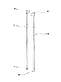
以下、添付図面を参照して本発明の実施形態を詳細に説明する。図1は本発明の多用途(化粧用具)ケースを示す斜視図である。図2は図1のケースの引出した状態を示す斜視図である。図3は図1の断面図である。図4は図3のケースの引出した状態を示す断面図である。図5は図1の分解斜視図である。
【0038】
図1及び図2に示したように、端部が円錐形で中空円筒形の上段ケース13と、中空円筒形の中段ケース12と、中空円筒形の下段ケース15とは互いに結合され、下段ケース15の下部にはキャップ16が嵌合されている。
【0039】
下段ケース15は上下に移動できるように中段ケース12の下部に嵌合される。下段ケース15の移動に対し芯部ロッド31は反対方向へ移動し、上段ケース13内部の芯部ロッド31の先端に設けた芯部材33が上段ケース13の開口部から出てくる。
【0040】
本発明の引出及び収納自在な多用途ケースについて図3〜図5を参照して説明する。まず、各部品について説明する。移動ロッド9は、下部にネジ溝111を設けたネジ回転運動部112を形成し、上部には内側にネジ溝221を形成し、その上部に結合溝131のある皿部124を備えている。
【0041】
固定パッキング120は、円筒管の構造であってその外側両側に一直線の嵌合溝211を形成し、移動ロッド9の結合溝131と嵌合する結合突起122を下部の外側に形成し、内側に縦方向の案内溝114を形成している。
【0042】
芯部ロッド31は、皿部124の上部内側に挿入して皿部124のネジ溝221とネジ組み立てできるように下段部にネジ突起321のある芯上下運動ネジ部322を設けている。
【0043】
案内部材115は、芯部ロッド31の左右対称に設け、上下直線方向に案内可能に固定パッキング120の嵌合溝211とキャップ16の嵌合溝42間に設ける。芯部18は、芯部ロッド31の上部で結合し、終端には取付け結合した芯部材33を備えている。
【0044】
キャップ16は、移動ロッド9下部のネジ回転運動部112のネジ溝111がネジ組み立て可能なように内側にネジ突起55を形成し、外側上部には直角に内側へ嵌合溝42を形成し、外側下部には受け突起59を形成している。
【0045】
上段ケース13は、上部先端が開口した円錐形である。中段ケース12は、上部外側は上段ケース13の下部内側に取付け結合し、内部に固定パッキング120及び移動ロッド9の上部と中間部を内装するよう全体が円筒管で形成している。
【0046】
下段ケース15は、内側上部は中段ケース12の中間部又は下部外側と密着し、内側下部はキャップ16の受け突起59の上部と取付け結合してキャップ16と共に動くようになっている。
【0047】
芯部ロッド31のネジ突起321と移動ロッド9のネジ溝111は、逆方向のスクリュウを形成する。移動ロッド9下部のネジ回転運動部112のネジ溝111とキャップ16内側のネジ突起55は互いにネジ組み立て、引出及び収納時にキャップ16を下段ケース15とともに上下運動させる際に、上下運動を移動ロッド9の回転運動に変換させる。
【0048】
変換させた移動ロッド9の回転運動については、移動ロッド上部皿部124内側のネジ溝221と芯部18の芯上下運動ネジ部322のネジ突起321とネジ組み立てているので、芯部18が上下運動に変換されて芯部材33の引出及び収納が行えるようになる。
【0049】
固定パッキング120の下部外側の結合突起122は、移動ロッド9上部の結合溝131と嵌合して移動ロッド9の位置を固定する。これにより下段ケース15の上下運動が移動ロッド9の回転運動に変換する。
【0050】
さらに、皿部124上部の内側中央には結合溝131を形成している。円筒管構造の固定パッキング120については、パッキング本体の外径より結合突起122のある下部の外径のほうが小さくなっている。その理由は、結合突起122は移動ロッド9の結合溝131に嵌合するので、引出及び収納時に芯部ロッド31が上下に往復運動する際摩擦を軽減するためである。
【0051】
キャップ16はその断面がほぼU字形である。内側には移動ロッド9の下部に形成したネジ回転運動部112のネジ溝111とネジ組立できるようネジ突起55を左右に2個形成している。外側下部には受け突起59を形成しており、受け突起59の上部には下段ケース15を嵌め一緒に動くようになっている。
【0052】
一方、キャップ16外側円周上部には直方体形状の嵌合溝42が形成されている。案内部材115は中段ケース15の内側と密着して嵌合溝42と一端が結合しており、芯部ロッド31が上下運動して芯部材33の引出及び収納する際に、ぶれないで真直ぐ作動するようにガイドの役目をする。
【0053】
キャップ16は金属材料を用いるのが望ましいが、軽くて触感が優れる合成樹脂、ラバー、及びシリコンなどを用いることができる。
【0054】
上段ケース13はその上部先端が開口した円錐形状で、全体は円筒管構造である。内側下部を中段ケース12の外側上部と取り付け結合する。
【0055】
中段ケース12は全体が円筒形状であり、外側上部を上段ケース13内側下部と取り付け結合する。
【0056】
一方、中段ケース12下部外径は下段ケース15の内径と比較すると小際。その理由は芯部材の引出及び収納の上下運動時に下段ケース15との摩擦を減らすところにある。なお、中段ケース12は下段ケース15の内側と密着されており取付けられてはいない。
【0057】
芯部材33の引出し時には外に出てきて外観が見れる状態となるが、収納時には上段ケース13と下段ケース15により完全に覆われる。
【0058】
図18に示したように、下段ケース15と後述の円筒形状のスライダー92について、内側上部は上段ケースの下部に設置し、中段ケース12の外側と下段ケース15の上部内側の間に密着される。スライダー92は下段ケース15と中段ケース12に挟まれて引出及び収納時の摩擦による中段ケース12外側に傷ができるのを防ぐものである。スライダー92はクロムメッキして硬度の高い物質との摩擦による傷などを防ぐようになっている。
【0059】
さらに、リップスティック、リップブラシ、頬ダッチブラシ等の芯部材33を嵌合する芯部18がある。芯部18の下部には皿部124内側のネジ溝221とネジ組立てるようにネジ突起321のある芯上下運動ネジ部322を形成した芯部ロッド31を取付け結合している。
【0060】
次に、図4を参照して本発明の動作を説明する。先ず、一方の片手で上段ケース13を持ち、他の片手でキャップ16又は下段ケース15を持って、キャップ16を下方へ下げればキャップ16とネジにより組立てた移動ロッド9が回転する。
【0061】
それにより移動ロッド9上部の皿部124内側のネジ溝221とネジ組立てた芯上下運動ネジ部322が上昇して芯部材33が上段ケース13の外側へ押し出される。すなわち、リップブラシ、リップスティック(L)、頬ダッチブラシ等が結合された芯部材33が使用できるようになる。
【0062】
リップブラシ、リップスティック、頬ダッチブラシなどの芯部材33を用いないときは一方の片手で上段ケース13を持ち、他方の片手でキャップ16又は下段ケース15を上に上げると、芯上下運動ネジ部322が下降しながら芯部材33が上段ケース13の中に入って収納状態になる。さらにキャップ16を机などに押し当てて芯部材33を上段ケース13内部へ収納するなど片手で簡単にしまうこともできる。
【0063】
下段ケース15はキャップ16と一体で動くので、上下運動により引出す時にはキャップ16と下段ケース15が一緒に下方へ移動し、中段ケース12外側が外部へ露出して全体の長さは最大となる。収納時には中段ケース12外側が上段ケース13及び下段ケース15により覆われてケース全体の長さが最小になる。
【0064】
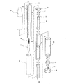
図6は本発明の実施形態の1つであり、シリンダー方式の多用途(化粧用具)ケース構造の断面図である。図7は図6の動作を示す断面図である。図8は図6の分解斜視図である。図6〜図8で示すように、本願発明の引出及び収納自在の多用途ケースはシリンダー2とその左右両側に結合した芯部ロッド8とキャップロッド10とを設ける。
【0065】
シリンダー2は円筒形状である。シリンダー2の中間には隔板3を設けている。隔板によりシリンダー2の内部が左右に分けられる。左側には芯部ロッド8が結合する第1チェンバー4を形成し、右側にはキャップロッド10が結合する第2チェンバー5を形成している。
【0066】
芯部ロッド8及びキャップロッド10の端部にはゴムパッキング、シリコンなどでシール24処理してシリンダー2に結合して移動するときシリンダー2内の空気が漏れないようにする。シリンダー2の内周面には第1チェンバー4の内部から第2チェンバー5の内部へ連結する第1空気通路6を長さ方向に形成しており、反対側には第2チェンバー5の内部から第1チェンバー4の内部へ連結する第2空気通路7を形成している。
【0067】
第1空気通路6及び第2空気通路7は、シリンダー2に結合する芯部ロッド8及びキャップロッド10の移動時にロッドにより圧縮された空気が流れる通路であって第1チェンバー4及び第2チェンバー5へ移送可能となる。
【0068】
図6を用いてより具体的に説明する。芯部ロッド8とキャップロッド10がシリンダー2に結合した状態(芯部ロッドとキャップロッドとが全て前進している状態)でいずれか一方のロッドを引っ張ると、望ましくはキャップロッド10を引っ張ると、第2チェンバー5にあった空気が圧縮されると同時に第2空気通路7を通して第1チェンバー4へ流入し、空気の圧力によって芯部ロッド8を前方に押す。すなわち、芯部ロッド8が上段ケース13の外側へ移動するようになる。
【0069】
シリンダー2の外周面には横方向にスロット26を長めに形成し、反対側にも同一な幅のスロット26を対称に形成している。そこには後述する本発明の開閉部材が嵌め込めれる。シリンダー2の左右には芯部ロッド8及びキャップロッド10の移動の際に、空気が漏れないようシール24を設けたパッキング蓋21,23が設けられる。シール24はゴム、シリコン等のオーリング(O-Ring)を用いる。
【0070】
続いて、芯部ロッド8の一端には中心内側方向へ結合溝11を形成し、結合溝11には芯部材33を設けた芯部18を結合する。芯部ロッド8の他端(ヘッド部分)はシリンダー2の第1チェンバー4に挿入する。キャップロッド10の一端にも中心内側方向へ結合溝11を形成し、結合溝11にはキャップ16の突部17を結合する。キャップロッド10の他端(ヘッド部分)はシリンダー2の第2チェンバー5に挿入する。
【0071】
芯部ロッド8と、キャップロッド10と、シリンダー2の連結構成は次のようである。シリンダー2の第1チェンバー4と第2チェンバー6にそれぞれ芯部ロッド8とキャップロッド10を結合させており、キャップロッド10が動けば芯部ロッド8はキャップロッド10と反対方向へ動く。すなわち、キャップロッド10を引っ張ると同時に圧縮された空気が芯部ロッド8を押して芯部18が出るようになる。キャップロッド10を引張る動きは芯部ロッド8と反対方向への動きなので、芯部ロッド8と結合した芯部18が上へ出るようになる。
【0072】
引出及び収納自在の多用途ケースの外側、すなわちシリンダー2の外周面には円筒形の中段ケース12を嵌合され固定する。中段ケース12は、弾力性のある材質を用いてシリンダー2の外周面と弾力的に密着させて第1空気通路6と第2空気通路7とを通過する空気がシリンダー2の外側へ漏れないようにする。
【0073】
中段ケース12の上部外周面には上段ケース13を嵌合され固定結合させ、中段ケース12の下部外周面には下段ケース15を嵌合され外周面に沿って動く。下段ケース15の下部端部にはキャップ16を結合させる。キャップ16の一方側に形成した突部17をキャップロッド10の結合溝11に嵌合することで一体となって作動する。
【0074】
芯部ロッド8の結合溝11には芯部18の一端を結合する。芯部18の他端には化粧用ブラシ、例えばリップブラシ、アイブラシ、リップスティック等を嵌合され用いることができる。ボールペン芯、鉛筆芯、サインペン、等の文具用筆記具を嵌合され用いることができる。さらに、芯部材33に用る筆記具には画筆を用いることもある。
【0075】
本発明の構成についてもう少し述べる。シリンダー2と中段ケース12を固定している。シリンダー2に挿入設置しているキャップロッド10をキャップ16に固定している。キャップ16は下段ケース15を固定している。下段ケース15は中段ケース12と結合してスライディング可能に設けているので、下段ケース15又はキャップ16を握って引張るとシリンダー2内に設けたキャップロッド10が下方に引張られ、反対に芯部ロッド8は引出されるのである。
【0076】
上述のように構成される本発明の作動を説明すれば次のとおりである。先ず、芯部材33が結合した芯部18、本実施形態においては化粧部材を使用しようとする場合には、片手で上段ケース13を握り他の片手では下段ケース15を握って外側へ引張る。
【0077】
そうすると下段ケース15は下方向へ引張られながらキャップロッド10の内側の端部が第2チェンバー5の開口側へ移動する。それと同時に、キャップロッド10の内側端部で圧縮された空気は第2空気通路7を通して芯部ロッド8の内側端部と第1チェンバー4の内側空間の間に移送される。すなわち、第2チェンバー5にあった空気が移送されて第2空気通路7に沿って第1チェンバー4に入って芯部ロッド8を押し出すようになる。
【0078】
すなわち、第2チェンバー5内の空気が第1チェンバー4へ移送され、その空気圧により芯部ロッド8の端部が第1チェンバー4の開口側へ押される。結局芯部ロッド8に配した芯部18が上部方向へ移動し芯部18に結合する芯部材33が引出される。
【0079】
ここで、芯部ロッド8の内側端部が開口側へ移動すると同時に第1チェンバー4に存在していた空気は徐々に圧縮されて第1空気通路6へ移送が行われる。つまり、その通路に沿って第2チェンバー5内側へ移送されるのでキャップロッド10の内側端部が開口側へ円滑に移動するのである。
【0080】
芯部18を引出して使用後に芯部18を内側へ戻すには、さらに上段ケース13と下段ケース15を握って軽く押せば良い。すると空気の移送が反対に行われ芯部ロッド8が元の収納状態に戻る。
【0081】
空気の移送について詳述する。下段ケース15と結合したキャップロッド10の端部が第2チェンバー5側へ移動して内部の空気を圧縮する。圧縮された空気は第2空気通路7を通して芯部ロッド8の端部側へ移送される。移送された空気は芯部ロッド8の端部を第1チェンバー4の開口側へ押し出す。
【0082】
そのとき芯部ロッド8の内側の端部が第1チェンバー4の開口側へ押されて第1チェンバー4の空気を圧縮する。圧縮された空気は第1空気通路6を通してキャップロッド10の端部側へさらに移送され、キャップロッド10が第2チェンバー5の開口側へ円滑に動くのである。
【0083】
上記動作と同時に芯部ロッド8と芯部18は上昇し、芯部材33と芯部18の引出及び収納作業を自動的に行うことができる。
【0084】
図9は本発明の他の実施形態であり、引出及び収納自在の多用途ケースを筆記具として用いるときの構造を示す断面図である。図10は図9の分解斜視図である。図11は本発明の他の実施形態を示す断面図である。図12は図11の分解斜視図である。
【0085】
図9〜図10を参照して説明する。本発明の引出及び収納自在の多用途ケースは以下のようである。上段ケース13は中空円筒形の管状であり下部内側には雌ネジ部19を形成している。
【0086】
芯部18は、上段に芯部材33を結合し下段の内側に雌ネジ部19を形成している。
固定パッキング14は、上段ケース13の雌ネジ部19に嵌合することができるように雄ネジ部41を外側に形成し、内側には固定溝57を形成し、さらに縦方向の案内溝114を形成している。
【0087】
芯部ロッド8は、芯部18の雌ネジ部19と嵌合することができるように上段部に雄ネジ部41を形成し、その下段部にネジ突起321を備えた芯上下運動ネジ部322を形成しており、その上部のロッド左右側に縦方向へ案内突起113を形成している。
【0088】
移動ロッド9は、上段部の外周面に固定パッキング14の固定溝57に固定する結合突起43を形成し、内側にはネジ溝111を形成し、内側上段部には押出し防止溝44を形成すると同時に下段部にはネジ突起321を設けたネジ回転運動部112を形成している。
【0089】
キャップロッド10は、縦方向のスライディング溝47を形成し、下段部外側には雄ネジ部41を形成し、内側にはネジ溝111を形成している。
【0090】
中段ケース12は、やや上部の外側表面に上段ケース13と下段ケース15とを分離する分離顎53を形成し、キャップロッド10のスライディング溝47と結合して左右への回転を防ぐために内側へ盛り上がったスライディング顎46を形成している。
【0091】
下段ケースは中段ケース12と結合してスライドできるように設ける。キャップ16は、下段ケース15の下部に取付けて結合させ、キャップロッド10の雄ネジ部41と結合する雌ネジ部19を形成している。
【0092】
クリップ45は、下段ケース15の底面とキャップ16の上面の間に嵌められて固定できるように孔部56を形成している。芯部材33には筆記具としてクレパス、サインペン等を用いる。
【0093】
移動ロッド9のネジ突起321と芯部ロッド8のネジ突起321は、互いに反対方向へ回転するように逆スクリュウの突起を形成する。このような本発明の構造と動作を説明する。先ず、上下に移動可能な移動ロッド9のネジ突起321をキャップロッド10の内側に形成したネジ溝111と結合してネジ移動するように設ける。
【0094】
芯部ロッド8の芯上下運動ネジ部322は移動ロッド9の内側に形成したネジ溝111と結合してネジ移動できるように設ける。移動ロッド9の上部外側に固定パッキング14を嵌合すると固定溝57が結合突起43と結合する。芯部ロッド8の上段に形成した雄ネジ部41に芯部18の雌ネジ部19を嵌合する。
【0095】
キャップロッド10外周面に中段ケース12を嵌合する。中段ケース12の分離顎53を基準として下側にはスライディング可能できるように下段ケース15を嵌め、分離顎53の上側には上段ケース13を嵌合する。上段ケース13は固定パッキング14に嵌合するので、芯部ロッド8がネジ移動して芯部18を引出すのである。
【0096】
芯部ロッド8の案内突起113と固定パッキング14の案内溝114が結合して上下に直線移動が可能になると、キャップロッド10のスライディング溝47と中間ケース12のスライディング顎46が結合して左右回転の動きを止める役割をする。
【0097】
具体的に動作を記述する。下段ケース15又はキャップ16を握って引張ると、キャップ16と嵌合しているキャップロッド10が引張られ、下段ケース15は下方向へスライドする。そのとき、キャップロッド10の内側に結合した移動ロッド9が一定方向(時計方向)へネジにそって回転する。
【0098】
それと同時に移動ロッド9の内側に結合した芯部ロッド8は、移動ロッド9が回転(時計方向)すると案内溝114に結合した案内突起113により直線的に上昇する。したがい、芯部ロッド8に固定した芯部18が上段ケース13の開口部へ引出される。
【0099】
図11〜図12は本発明の他の実施形態を示す断面図と分解斜視図である。芯部材33にボールペン芯のように長いものを用いる場合を示している。本発明の引出及び収納自在の多用途ケースの構造と動作は前述同様であるから同じ構成のものは同一の符号を用い、芯部材の引出し動作については図9〜図10を参照にする。
【0100】
先ず、本発明の上記実施形態においては、ボールペン芯等の長い芯部材33を使用するため芯部材33の上段部の両側へ固定顎101を形成する。芯部材33の固定顎101の上部にスプリング100を嵌合され弾力的に固定するようにし、芯部材33の下段部は芯部ロッド8の内側に嵌合され固定する。芯部ロッド8はその内側の下部の底面に楔52を形成しておりボールペン芯の芯部材33を嵌合され固定する。
【0101】
図13は本発明の他の実施形態であって、シリンダー方式の多用途(筆記具)ケースの構造を示す断面図である。図14は図13の分解斜視図である。図13及び図14に図示のとおり本発明の実施形態は図6〜図8を参照にする。同一の符号については説明を省くことにする。
【0102】
図6〜図8では芯部18に結合する芯部材33に化粧用具を用いたが、本実施形態においてはボールペン芯のような長い芯部材33を芯部ロッド8の内側に深く差し込んで使用するものである。したがって、芯部ロッド8の内側にポールペンの芯を嵌合するように細長い孔を形成して芯部材33を嵌合され固定させる。
【0103】
図15は本発明の他の実施形態であり、スクリュウ方式の多用途(化粧用具)ケースに開閉部材を設けた態様を示す斜視図である。図16は図15の動作を示す斜視図である。先端が円錐形で中空円筒の上段ケース13と、中空の上段ケース13の下部内側に嵌合する円筒形の中段ケース12と、中空の中段ケース12の下部外側に嵌合する下段ケース15とが互いに結合しており、下段ケース15の下部にはキャップ16を嵌合している。
【0104】
下段ケース15は中段ケース12の下部で嵌合して上下に移動する。下段ケース15が移動することで上段ケース13は相対的に反対方向へ移動し、ケース内部の芯部18に設置した芯部材33が上段ケース13の開口から出るようになる。ケース内には、内部への塵又は異物などの侵入を防ぐために、蓋又はカバーの役割をもつ開閉部材30,32を設けて自動的に開閉させる。
【0105】
図17は図15の断面図である。図18は図17のA部拡大図である。図19は図15に図示する本発明の動作を示す断面図である。図20は図15の分解斜視図である。図17〜図20について以下に説明する。移動ロッド9は、下部にはネジ溝111のあるネジ回転運動部112を形成し、上部には内側にネジ溝221を形成し、その上部に結合溝131を形成した皿部124を備える。
【0106】
固定パッキング120は、円筒管構造であってその外側の両側に垂直な一直線の嵌合溝211を形成し、移動ロッド9の結合溝131と嵌合する結合突起122を下部外側に形成しており、内側に縦方向の案内溝114を形成している。
【0107】
芯部ロッド31は、皿部124の上部内側に挿入する。下部では皿部124のネジ溝221とネジ組み立てできるようにネジ突起321のある芯上下運動ネジ部322を形成し、上部のロッド左右対称に縦方向の案内突起113を形成している。芯部18は、芯部ロッド31の上部で結合し、末端に取付けて結合する芯部材33を備える。
【0108】
キャップ16は、移動ロッド9下部のネジ回転運動部112のネジ溝111とネジ組み立てできるように内側にネジ突起55を形成し、外側上部には直方体形状の嵌合溝42を形成し、外側下部には受け突起59を形成している。上段ケース13は上部の先端を開口した円錐形状である。
【0109】
開閉部材30,32は、化粧用品を引出す場合には上部の一端が互いに離れ、収納時には離れた一端が互いに接触できるように半円形のカバー36を形成している。中間部は固定パッキング120の嵌合溝211に嵌合することができるように真直ぐに形成し、下部はキャップ16の嵌合溝42に嵌合され回転が防げるように突起34を直角に折り曲げて形成している。
【0110】
上段ケース13は、上部は先端を開口した円錐形であり、中間部及び下部は開閉部材30、32の上部及び中間部を内蔵できるように形成している。
【0111】
中段ケース12は、上部外側は上段ケース13下部内側に取付け結合し、内側は開閉部材30,32の中間部と密着し、内部に固定パッキング120及び移動ロッド9上部及び中間部を内蔵できるように円筒管で形成している。
【0112】
下段ケース15は、内側上部は中段ケース12の中間部又は下部外側と密着し、内側下部はキャップ16の受け突起59上部で嵌合してキャップ16と共に動くようになっている。
【0113】
移動ロッド9下部のネジ回転運動部112の結合溝111とキャップ16内側のネジ突起55は互いにネジ組立てられており、引出及び収納のためキャップ16と下段ケース15と共に上下運動する際移動ロッド9を回転運動へと変換する。
【0114】
移動ロッド9上部の皿部124内側の結合溝221と芯部18の芯上下運動ネジ部322のネジ突起321とがネジ組立てられている。このため、芯部は上下運動に変わり本発明の芯部材33の引出及び収納が行われる。
【0115】
固定パッキング120の下部外側の結合突起122は移動ロッド9上部の結合溝131と嵌合して移動ロッド9位置を固定するので、下段ケース15の上下運動は移動ロッド9を100%回転運動に変換させる。
【0116】
皿部124の上部内側には結合溝131が形成されている。円筒構造の固定パッキング120について、結合突起122のある下部の外径はパッキング本体の外径より小さくなっている。結合突起122は移動ロッド9の結合溝131に嵌合するので、その状態で開閉部材30,32同士の隙間と芯部ロッド31の直径とがほとんど同じか僅かに小さくし、引出及び収納時に芯部ロッド31が上下に往復運動をするときに伴う摩擦を少なくするためである。
【0117】
キャップ16はその断面が概ねU字形である。内側には移動ロッド9の下部に形成したネジ回転運動部112外側のネジ溝111とネジ組立て可能なようにネジ突起55を左右に2個形成している。外側下部には受け突起59を形成している。受け突起59の上側には下段ケース15を一緒に動くように取付ける。
【0118】
開閉部材30,32の断面が半円形のカバー36は、キャップ16及び下段ケース15を下方に押して化粧用品を引出すとき芯の厚さ位離れるように弾力性のある材量で作成する。反対にキャップ16及び下段ケース15を上に押して化粧用品を収納するときは、開閉部材30、32が上段ケース13に接近すると同時にそのカバー36が互いに接触するようにする。これにより、従来技術の問題点である異物侵入及び芯部材33の損傷を防ぎ、自動開閉ができて、蓋が不要となる。
【0119】
開閉部材30、32の中間部分は固定パッキング120の嵌合溝211に嵌合することができるように真直ぐに形成している。下部はキャップ16の嵌合溝42と結合し回転を防ぐように直角に折曲げた突起34を設けている。突起34は多段に折り曲げても良く、一対以上設ければ良く、固定可能にすれば良いものであり多様の変形仕様が可能である。
【0120】
キャップ16外側上部には直方体状の嵌合溝42を形成しており、開閉部材30、32下部の突起34を嵌合する。下段ケース15及びそれに嵌めた開閉部材30、32を回転させようとしても開閉部材30、32の内側と密着している固定パッキング120により回転が阻まれる。芯部ロッド31が上下運動することで引出及び収納を行うことができるようにしている。
【0121】
キャップ16は金属材量を用いることが望ましいが、軽く触感を優しくするため合成樹脂、ラバー及びシリコン等の材質を用いることができる。
【0122】
上段ケース13は、上部先端を開口した円錐形状に成型し、中間部及び下部は開閉部材30、32の上部及び中間部を内蔵するように形成し、全体が円筒構造であり、内側下部には中段ケース12の外側上部を嵌合する。
【0123】
中段ケース12の内径は、開閉部材30、32を組み立てた外寸とほとんど同一又は僅か大きくする。中段ケース12は全体が円筒形状でその外側上部は上段ケース13の内側下部と嵌合され、内側は開閉部材30,32の中間部と密着している。
【0124】
中段ケース12下部の外径は下段ケース15の内径と比較すると僅かに小際。芯部材の引出及び収納の上下運動において下段ケース15との摩擦を減らすためである。下段ケース15と密着してはいるが取付けてはいない。また、芯部材33の引出時には外観が見れるが、収納時には上段ケース13と下段ケース15により完全に覆われる。
【0125】
図18に示すとおり、下段ケース15と後述する円筒形状のスライダー92は内側下部が下段ケース15の受け突起59上部と取付け結合してキャップと共に動くようになっており、内側上部は中段ケースの中間部及び下部外側と密着している。下段ケース15と中段ケース12の間には引出及び収納時の摩擦により中段ケース12外側に傷ができるのを防ぐように円筒形のスライダー92が下段ケース15内側上部に嵌合されている。
【0126】
スライダー92はクロムメッキすることで硬度が高い物質との摩擦による傷等を防止する。さらに、リップスティックなどの内容物を容れる部品である芯部18が別個にある。芯の下部には皿部内側のネジ溝221とネジ組するようにネジ突起321のある芯上下運動ネジ部322を形成し、芯部18の上部には芯部材33を嵌合している。
【0127】
動作は次のようである。先ず、一方の片手で上段ケース13を握り、もう一方の片手でキャップ16を握ってキャップ16を下方に下げればキャップ16とネジ組している移動ロッド9が回転するようになる。それにより、移動ロッド9の上部の皿部124内側のネジ溝221とネジ組している芯上下運動ネジ部322が上昇して芯部材33が上段ケース13の外部へ引出される。これによりリップブラシ、リップスティック(L)、頬ダッチなどが使用できる状態となる。
【0128】
リップブラシ、リップスティック、頬ダッチなどの芯部材33を使用しないときには、一方の片手で上段ケース13を握りもう一方の片手でキャップ16を上にあげる。すると、芯上下運動ネジ部322が下降して芯部材33は上段ケース13の中に入る。同時に開閉部材30,3の2上部先端のカバー36が互いに接触して収納状態となる。
【0129】
さらにキャップ16を机などに当てて押して芯部材33を上段ケース13内部へ戻すなど、片手でも簡単に収納することができる。図示のように、下段ケース15はキャップ16と一体に動くので、上下運動による引出時にはキャップ16と下段ケース15とが一緒に下へ移動する。中段ケース12の外側は外部に露出されケース全体の長さは最大になり、収納時には中段ケース12外側が上段ケース13及び下段ケース15により覆われケース全体の長さは最小となる。
【0130】
図21は本発明の他の実施形態を示す断面図である。図22は本発明の開閉部材を示す拡大斜視図である。図23は本発明の開閉部材の一実施形態を示す斜視図である。図21に示すとおり、固定パッキング120と、開閉部材30,32と、上段ケース13、中段ケース12及び下段ケース15と、円筒形のスライダー92と、芯部18の構造は前述の実施形態と同一であるが、移動ロッド9下部とキャップ16上部の構造は若干違っている。
【0131】
すなわち、キャップ16の上下運動を移動ロッド9の回転運動に変換させる構成である。図17〜図20に示した実施形態のような移動ロッド9下部にネジ溝のある長めのネジ回転運動部112を形成する必要がなく、移動ロッド9は単純に円筒管構造にする。この場合、円筒管の内側と外側とに形成するネジ溝221,222はそれぞれ逆スクリュウに形成する。
【0132】
移動ロッド9の外側には移動ロッドの中心から半径が大きいネジ溝222を形成する。図21のB部に図示のように、外側の半径が大きいネジ溝222と組立てできるるようキャップ16のネジ突起55の半径を大きくする。そのためキャップ16を2段に形成してその上部にネジ突起55を設ける。
【0133】
さらに、本発明は上記実施形態のほかに、外部に段階的に引出及び収納のための掛止装置など追って構成することができる。
【0134】
図22〜図23は本発明の蓋及びカバーの役割をなす一対の開閉部材30,32を示す図面である。上段部には半円形のカバー36を形成して互いに向い合って閉じるようになっている。若干曲がるように形成して上下移動時に上段ケース内部と接触しないようにし、中段部は細く薄いストリップ状態になっている。下段部には芯部ロッド8に固定する突起34をカギ字(┐)状に折り曲げて設けている。
【0135】
図23に図示したものは、断面が半円形状の一対のカバー37である。下段部は二重突起35を形成しておりさらに堅固に固定できる。半円形のカバー36,37は本発明の実施形態では互いに接触する部分の断面形状を長方形としたがラウンド形、三角形、四角形等多様に形成可能なことは勿論である。
【0136】
図24は本発明の実施形態としてスクリュウ方式を適用した移動ロッドと移動ロッド案内管との結合関係を示す分解斜視図である。図25は図24の構造を示す斜視図である。図26は図25の動作を示す動作斜視図である。図24〜図26に示すとおり、本発明実施形態の移動ロッド9は上段に皿部124を形成し、その外周面上部に突出顎60を縁に沿って形成している。下段部にはスリットを設けた楔形状の固定チップ62を形成しており、多数のネジ突起64も形成している。
【0137】
皿部124の内側にはネジ溝221を形成している。そして、ネジ溝221の末端部には押出し防止溝44を形成している。押出し防止溝44は芯部材として用いるブラシが強制的に押されて下ってこないように固定する役割をする。ネジ突起321とネジ溝221は互いに反対方向の逆スクリュウに形成させる。
【0138】
移動ロッド9と結合するキャップロッド77には外周面に縦方向にスライディング溝47を形成し、上段外周面には一対の溝68を対称に形成し、内側の面にはネジ突起64と結合させるネジ溝70を形成する。
【0139】
移動ロッド9はキャップロッド77の内側に挿入する。すると移動ロッド9のネジ突起64がキャップロッド77のネジ溝70と結合し、キャップロッド77が上下に移動して移動ロッド9は回転するようになる。
【0140】
中段ケース76の下部内側に縦方向に形成したスライディング顎46はキャップロッド77のスライディング溝47と結合する。このため、上下には移動可能となるが左右への回転は防ぐことができる。
【0141】
縦方向のスライディング顎46を形成させたものが望ましいが、左右回転を防ぐことのできる構造、例えばケース又はケースの内部を四角形、多角形等にすれば全て可能であり、それは当業者には容易なる形状変更と言うべきである。
【0142】
楔形状の固定チップ62はキャップロッド77と結合しており、移動ロッド9を引っ張ってキャップロッド77を回転させることができる。
【0143】
移動ロッド9は芯部材案内バー80の下側に嵌合する。そのとき芯部材案内バー80の下段内側に形成した円形の固定溝61に移動ロッド9の円形の突出顎60を嵌合する。芯部材案内バー80は上部に芯部材として用いるブラシを支持することができるよう縦溝(未図示)を形成した一対の支持バー84を備え、下段にはスロット82を形成している。
【0144】
本発明実施形態は、本発明の化粧用品ケースに適用される構成と同様に適用することができる。さらに、本発明におけるような移動ロッド9に形成した押出し防止溝44と、キャップロッド77に形成したスライディング溝47、及び中段ケース76に形成したスライディング顎46等は化粧用品ケースのほかに文房用具、画筆類等に多様に適用することができる。
【0145】
図27は本発明にシリンダー方式を利用した多用途(化粧用具)ケースの構造を示す断面図である。図28は図27の動作を示す断面図である。図29は図27の分解斜視図である。
【0146】
本願発明の引出及び収納自在な多用途ケースは図27〜図28に図示したように、シリンダー2とその両側にそれぞれ結合した芯部ロッド8とキャップロッド10を備える。シリンダー2は円筒形状である。シリンダー2の中間には隔板3を設け、その隔板3によってシリンダー2内部が左右に分けられる。左側には芯部ロッド8を結合した第1チェンバー4を形成し、右側にはキャップロッド10を結合した第2チェンバー5を形成する。
【0147】
芯部ロッド8及びキャップロッド10の端部にはゴムパッキング、シリコンなどによりシール24処理してシリンダー2に結合させ、移送時にシリンダー2内の空気が漏れないようにする。シリンダー2の内周面には第1チェンバー4の内部から第2チェンバー5の内部へ連結する第1空気通路6を長さ方向に形成し、その反対側には第2チェンバー5の内部から第1チェンバー4の内部へ連結する第2空気通路7を形成している。
【0148】
第1空気通路6及び第2空気通路7はシリンダー2に結合した芯部ロッド8及びキャップロッド10の移動時に、ロッドにより圧縮された空気が流れる通路であって第1チェンバー4及び第2チェンバー5へ移送できる。
【0149】
具体的に説明する。図8のように芯部ロッド8とキャップロッド10がシリンダー2に結合した状態(芯部ロッドとキャップロッドが全て前進している状態)のものを、いずれか一方のロッド、望ましくはキャップロッド10を引張る。すると第2チェンバー5にあった空気は圧縮され、同時に第2空気通路7を通して第1チェンバー4へ流入した空気の圧力によって芯部ロッド8が押される。すなわち、芯部ロッド8が上段ケース13の先側に移動する。
【0150】
シリンダー2の外周面には長いスロット26を形成し、反対側に対称に同一幅のスロット26を形成している。そのスロット26には、一対の開閉部材30、32を嵌合され固定している。開閉部材30、32は一端をキャップロッド10と連結しておりキャップロッド10と共に滑りながら動く。シリンダー2の左右には芯部ロッド8及びキャップロッド10の移動時に空気が漏れ出ないようシール24を取り付け、それぞれにパッキング蓋21,23を設ける。
【0151】
一対の開閉部材30,32は、一端には内側に折り曲げた突起34を形成し、他端にはカバー36を形成している。カバー36は半円形状で開閉部材30,32が上昇したとき互いに閉じて異物の侵入を防ぐようになっている。カバー36は半円形状とするのが望ましい。カバー36が閉じて互いに接触する部分の断面形状は一文字形、鋸の歯形、ラウンド形など多様な形状とすることができる。
【0152】
芯部ロッド8の一端には中心内側方向に結合溝11を形成し、結合溝11には芯部材33を設けた芯部18を結合する。芯部ロッド8の他端(ヘッド部分)はシリンダー2の第1チェンバー4に挿入する。
【0153】
キャップロッド10の一端にも中心内側方向に結合溝11を形成している。結合溝11にはキャップ16の突部17を結合する。キャップロッド10の他端(ヘッド部分)はシリンダー2の第2チェンバー5に挿入する。
【0154】
芯部ロッド8と、キャップロッド10と、シリンダー2と、開閉部材30、32の連結構成は次のとおりである。シリンダー2の第1チェンバー4と第2チェンバー6にそれぞれ芯部ロッド8とキャップロッド10を結合する。シリンダー2の外周面に形成したスロット26には開閉部材30,32を嵌合され固定する。開閉部材30,32の端部に形成した突起34はキャップロッド10の端部に形成した固定溝25にそれぞれ嵌合され固定する。
【0155】
キャップロッド10が動くと開閉部材30,32はシリンダー2に形成したスロット26とともに動き、芯部ロッド8はキャップロッド10の反対方向に動く。すなわち、キャップロッド10を引張ると開閉部材30,32が一緒に引張られて開き、同時に圧縮された空気が芯部ロッド8を押すことで芯部18が出てくる。
【0156】
開閉部材30,32は芯部ロッド8と反対方向に動くので、芯部ロッド8に結合した芯部18が上に出ると、逆に開閉部材30,32は反対側の下に移動して上段ケース13の開口が開くのである。
【0157】
シリンダー2の外周面に円筒形の中段ケース12を嵌合され固定する。中段ケース12は弾力性のある材量で作成してシリンダー2の外周面に密着設置させ、第1空気通路6と第2空気通路7を通過する空気がシリンダー2の外側へ漏れるのを防ぐ。
【0158】
中段ケース12の上部外周面には上段ケース13を嵌合され固定結合する。中段ケース12の下部外周面には下段ケース15を嵌め、外周面に沿って動かすことができるようになっている。下段ケース15の下部端部にはキャップ16を結合させ、キャップ16の一方側に形成した突部17をキャップロッド10の結合溝11に嵌合するので一体になって動くのである。
【0159】
芯部ロッド8の結合溝11には芯部18の一端を結合する。芯部18の他端には化粧用ブラシ、例えばリップブラシ、アイブラシ、リップスティック等、を嵌合され使用する。ボールペン芯、サインペン等の文具筆記類を用いることもできる。
【0160】
本発明では開閉部材が閉じた状態で収納している。使用時には一方の片手で上段ケース13を握り、他方の片手で下段ケース15を握って外側へ引張る。すると下段ケース15が下方向に引張られてキャップロッド10の内側の端部が第2チェンバー5の開口側へ移動する。
【0161】
同時に、キャップロッド10の内側の端部(ヘッド部分)で圧縮された空気は第2空気通路7を通して芯部ロッド8の内側の端部と第1チェンバー4の内側の空間の間へ移送される。すなわち、第2チェンバー5にあった空気が圧縮されて第2空気通路7に沿って第1チェンバー4へ入り芯部ロッド8を押し出すことになる。
【0162】
言い換えれば、第2チェンバー5内の空気が第1チェンバー4側へ移送され、その空気圧により芯部ロッド8の端部が第1チェンバー4の開口側へ押されて芯部ロッド8に連結された芯部18が上部方向へ移動する。すると開閉部材30のカバー36は開きながら内側へ引き込み、芯部18に結合した芯部材33が引出される。
【0163】
芯部ロッド8の内側端部が開口側へ移動すると同時に第1チェンバー4内の空気は圧縮されて第1空気通路6へ移送される。結局第2チェンバー5の内側へ移送されるのでキャップロッド10の内側端部が開口側へ円滑に移動する。
【0164】
芯部18を引き出して使用した後芯部18を内側に戻すには、上段ケース13と下段ケース15を握って軽く押せば良い。そうすると上述の空気移送が反対に行われて開閉部材を初期の収納状態である閉じ状態に復帰できる。
【0165】
すなわち、下段ケース15と結合したキャップロッド10の端部が第1チェンバー5側へ移動して内部の空気を圧縮する。圧縮された空気は第1空気通路6を通して開口側の第1チェンバー4へ移送され、移送された空気は芯部ロッド8の端部を第2チェンバー4の内側に押す。
【0166】
芯部ロッド8の内側端部が第1チェンバー4の内側へ押されて第1チェンバー4の空気を圧縮し、圧縮された空気が第2空気通路7を通して開口側の第2チェンバー5へ移送されるのでキャップロッド10が第2チェンバー5の内側へ動くようになる。
【0167】
上記動作時にキャップ16とキャップロッド10の間に固定した開閉部材30、32が上昇する。それととともに、末端部のカバー36は上段ケース13の開口側を塞ぐようになる。本発明では芯部材33と芯部18の引出及び収納が自動的に行われ、異物の侵入を防ぐ蓋の役割を充分に果たすことができる。
【0168】
図30は本発明に係るロッド動作による空気の流れを示す断面拡大図である。シリンダーチェンバー内で芯部ロッド8及びキャップロッド10が結合した状態からキャップロッド10が矢印方向へ移動する。すると空気が第2空気通路7に沿って移送され第1チェンバー4へ入って芯部ロッド8を矢印方向へ押し出す。具体的なシリンダー2の空気圧の移動は図27〜図28に説明のとおり同一であるから省略する。
【0169】
図31は本発明の他の実施形態でありスクリュウ方式を利用した多用途(筆記具)ケースに開閉部材を設けた構造の断面図である。図32は図31の分解斜視図である。図33は本発明の別の実施形態であり、スクリュウ方式を利用した場合の多用途(筆記具)ケース構造の断面図である。図34は図33の分解斜視図である。
【0170】
図31〜図32に示した実施形態を参照して説明する。本発明の実施形態であって図9〜図10の構成と同一であり、上段ケース13と固定パッキング14の間に一対の開閉部材30,32を嵌合する。開閉部材30、32の下末端に形成した突起34をキャップロッド10の嵌合溝42に固定してキャップロッド10と一緒に動くようにしている。
【0171】
図33〜図34は本発明の実施形態であって芯部材33にボールペン芯を用いた場合のものである。図11〜図12と同一構成であり、異物がケースの内部へ侵入するのを防ぐため自動的開閉できる開閉部材30、32をさらに設ける。開閉部材30、32は上述のキャップロッド10に端部を固定してキャップロッド10と共に動くのである。
【0172】
図35は本発明の他の実施形態でありスクリュウ方式を対称に設けたときの多用途(化粧用具)ケースの構造の断面図である。図36は本発明の他の実施形態であってシリンダーを対称に設けたときの多用途(化粧用具)ケースの構造の断面図である。図37は図36の分解斜視図である。
【0173】
図35に示したように、固定パッキング120と、開閉部材30、32と、上段ケース13、中段ケース12及び下段ケース15と、円筒形のスライダー92と、芯部18の構造は図19に示したスクリュウ方式と同様である。前述の実施形態と同一であるものの、移動ロッド9の下部とキャップ16上部の構造に若干の差がある。図21に図示した本発明の実施形態と同一である。ただし、構造はキャップ16を基準として対称に形成したものとなっている。
【0174】
さらにもう一度記述すると、キャップ16の上下運動を移動ロッド9の回転運動に変換させる構成であって、前述の移動ロッド9の下部に別途にネジ溝のある長めのネジ回転運動部112を形成させず単純に移動ロッド9を円筒管構造とする。その内周面と外周面とのネジ溝を逆スクリュウに形成する。
【0175】
そして、移動ロッド9の外側には移動ロッドの中心から半径が大きいネジ溝221を形成する。図21のB部に図示したように、外側の半径が大きいネジ溝222と組み合わせできるようにキャップ16のネジ突起55の半径を大きくする。そのためキャップ16を2段に形成してその最上部にネジ突起55を設ける。
【0176】
そして、キャップ16を基準にして上記構造のものを対称に設けることで両側が活用できる。言い換えれば、一方側を化粧部材に用い、他方側を筆記具に用いることができる。また、両側全てを大きさ又は種類の異なる化粧部材を用いることができるし、両側に互いに異なる筆記具を結合して用いることもできるのである。
【0177】
さらに、本発明は上記実施形態の外に、外部に段階的に引出及び収納のための蓋又はカバー又は掛止装置などを追って構成することができる。本発明では図21の実施形態を用いて対称に構成した例を示したが、他の実施形態を用いて対称に構成させても無論良い。
【0178】
続いて、図36〜図37を参照して説明する。本発明の実施形態としてシリンダー方式でシリンダー2を一個利用したシングルタイプ(Single type)では、芯部ロッド及びキャップロッドをシリンダー2に嵌合され、動きは互いに反対方向であった。本発明のように、シリンダーを対称に両側に設けたデュアルタイプ(Dual type)では、一端に雌ネジ部を形成したキャップロッド10を両方向に配列する。キャップロッド10同士は中間の連結具27に連結している。連結具27の外周面は下段ケース15と結合固定してキャップロッド10共に動く。
【0179】
連結具27には両端に雄ネジ部23を形成し、キャップロッド10の端部に形成した雌ネジ部に嵌合され連結する。連結具27はキャップロッド10の末端部を連結固定するので、芯部ロッド8及びキャップロッド10が互いに反対方向に動けば連結具27に固定した開閉部材30,32は芯部ロッド8と反対方向へ動いて芯部18を引き出し、引込まれして開閉が行われる。
【0180】
シリンダー2の空気移送動作は図27〜図30で説明したものと同様であるから省略する。開閉部材30、32は一端にそれぞれ突起34を設け、他端には断面が半円形のカバー36を設ける。この本発明実施形態は本発明の化粧用品ケースに適用される構成と同一である。
【0181】
さらに、本発明の実施形態においては移動ロッド9に形成した押出し防止溝44と、キャップロッド77に形成したスライディング溝47及び中段ケース12のスライディング顎46を同一の位置又は類似位置に形成する。これにより回転防止、押出し防止ができることは明らかである。
【0182】
本発明は望ましい態様の実施形態に限定されることはない。また、請求範囲内で、発明の要旨を外れず、本発明が属する技術分野において通常の知識を有する者であれば、多様に変形して実施することが可能なことは勿論であるが、そのように変形して実施することは本発明の、核心要素として記載の、請求範囲内にあるものと言える。
【0183】
【発明の効果】
本発明の引出及び収納自在の多用途ケースは逆スクリュウ方式又はシリンダー方式により作動する。したがい、比較的少ない部品数でも使用が可能であり、部品生産工数、組立て工数及び人件費を節減することができ、単価を下げられる。
【0184】
既存の他のケースとは異なって手による蓋の開閉が不要で自動的に開閉できるので便利である。また、化粧品が手にくっつかず、別途に蓋も不要で紛失も無く、異物が侵入することもなく、片手で操作を容易に行うことができる。さらに、分解、組立てが容易で、かつ各部品の破損がないので再利用できる。
【0185】
そして、本発明の引出及び収納自在の多用途ケースは化粧用具のみならず文具類として問題なく使用でき、多種多様の筆記類に用いることができる。
【0186】
本発明の実施形態による効果は第一に、蓋が不必要であるなど、部品数が少なく、容易に組立て可能であり、化粧用品の収納時異物が侵入することがなく、使用時の部品の損傷、破損がなく、キャップの上下運動により各種の芯部材を容易に出し入れできる。
【0187】
第二に、両手でなく片手だけでも引出収納操作を容易に行うことができる。分解組立てが容易であり使用及び分解組立時の部品の破損がないので再利用ができる。
【0188】
第三に、芯部材の引出及び収納時に硬い物質との摩擦による傷等を防止できるだけでなく引出収納が円滑に行える。
【0189】
第四に、下段ケースとキャップが一体に動き上下運動の引出時にはケースの全体の長さが延び、収納時には縮むので収納が容易に行える。
【0190】
第五に、本発明のスクリュウ方式を利用した化粧用具又は筆記具は逆スクリュウ方式を利用して引出すので故障が少ない。
【図面の簡単な説明】
【図1】図1は本発明の引出及び収納自在の多用途(化粧用具)ケースを示す斜視図である。
【図2】図2は図1の動作斜視図である。
【図3】図3は図1の断面図である。
【図4】図4は図3の作動状態を示す断面図である。
【図5】図5は図1の分解斜視図である。
【図6】図6は本発明の他の実施形態であってシリンダー方式を適用した多用途(化粧用具)ケースの構造を示す断面図である。
【図7】図7は図6の動作状態を示す断面図である。
【図8】図8は図6の分解斜視図である。
【図9】図9は本発明の他の実施形態であって引出及び収納自在の多用途ケースを筆記具として用いるときの構造を示す断面図である。
【図10】図10は図9の分解斜視図である。
【図11】図11は本発明の他の実施形態を示す断面図である
【図12】図12は図11の分解斜視図である。
【図13】図13は本発明の他の実施形態であってシリンダー方式を用いた多用途(筆記具)ケースの構造を示す断面図である。
【図14】図14は図13の分解斜視図である。
【図15】図15は本発明の他の実施形態であってスクリュウ方式の多用途(化粧用具)ケースに開閉部材が設けられた状態を示す斜視図である。
【図16】図16は図15の動作を示す斜視図である。
【図17】図17は図15の断面図である。
【図18】図18は図17のA部拡大図である。
【図19】図19は図15に図示の本発明の動作を示す断面図である。
【図20】図20は図15の分解斜視図である。
【図21】図21は本発明の他の実施形態を示す断面図である。
【図22】図22は本発明の開閉部材を示す拡大斜視図である。
【図23】図23は本発明の開閉部材の一実施形態を示す斜視図である。
【図24】図24は本発明の他の実施形態であってスクリュウ方式に適用される移動ロッドと移動ロッド案内管との結合関係を示す分解斜視図である。
【図25】図25は図24の構造を示す斜視図である。
【図26】図26は図25の動作を示す動作斜視図である。
【図27】図27は本発明にシリンダー方式を利用した多用途(化粧用具)ケースの構造を示す断面図である。
【図28】図28は図27の動作を示す断面図である。
【図29】図29は図27の分解斜視図である。
【図30】図30は本発明のそれぞれのロッド動作による空気の流れを示す断面拡大図である。
【図31】図31は本発明の他の実施形態であってスクリュウ方式を利用した多用途(筆記具)ケースに開閉部材が設けられたときの構造を示す断面図である。
【図32】図32は図31の分解斜視図である。
【図33】図33は本発明のさらに他の実施形態であってスクリュウ方式を利用したときの多用途(筆記具)ケースの構造により芯部材にボールペン芯を利用したときの構造を示す断面図である。
【図34】図34は図33の分解斜視図である。
【図35】図35は本発明の他の実施形態であってスクリュウ方式を対称に設けたときの多用途(化粧用具)ケースの構造を示す断面図である。
【図36】図36は本発明の他の実施形態であってシリンダー方式を対称に設けたときの多用途(化粧用具)ケースの構造を示す断面図である。
【図37】図37は図36の分解斜視図である。
【符号の説明】
2 シリンダー
3 隔板
4 第1チェンバー
5 第2チェンバー
6 第1空気通路
7 第2空気通路
8 芯部ロッド
9 移動ロッド
10 キャップロッド
11 結合溝
12 中段ケース
13 上段ケース
14 固定パッキング
15 下段ケース
16 キャップ
17 突部
18 芯部
19 雌ネジ部
21 パッキング蓋
23 パッキング蓋
24 シール
25 固定溝
26 スロット
27 連絡具
30 開閉部材
31 芯部ロッド
32 開閉部材
33 芯部材
34 突起
35 二重突起
36 カバー
41 雄ネジ部
42 嵌合溝
43 結合突起
44 押出し防止溝
45 クリップ
46 スライデイング顎
47 スライデイング溝
52 楔
53 分離顎
55 ネジ突起
56 通孔
57 固定溝
59 受け突起
60 突出顎
61 固定溝
62 固定チップ
64 ネジ突起
68 溝
70 ネジ溝
77 キャップロッド
80 芯部材案内バー
82 スロット
84 支持バー
92 スライダー
100 スプリング
101 固定顎
111 ネジ溝
112 ネジ回転運動部
113 案内突起
114 案内溝
115 案内部材
120 固定パッキング
122 結合突起
124 皿部
131 結合溝
211 嵌合溝
221 ネジ溝
222 ネジ溝
321 ネジ突起
322 芯上下運動ネジ部[0001]
[Industrial application fields]
The present invention relates to a versatile case that can be pulled out and stored. More specifically, it is used for stationery tools such as makeup tools and writing tools used for makeup. The cylinder method or screw method allows the core member to be pulled out and stored, and at the same time, another opening and closing member is provided to automatically open and close it. The present invention relates to a versatile case that can be pulled out and stored.
[0002]
[Prior art]
In general, cosmetic tools such as cheek Dutch brushes, lipsticks, lip brushes, and eye brushes are used for the beauty of women and are used for makeup of actors. Since such a cosmetic tool is convenient and easy to carry and store, it is provided with a manual method, that is, a lid that is manually opened and closed, and the cosmetic tool is integrated with a screw, or a rod and a case, etc. In general, the brush is pulled out at the same time as the rod moves relative to each other and moves up and down along the screw.
[0003]
[Problems to be solved by the invention]
With conventional cosmetic tools, it is necessary to open and close the lid each time it is used. For this reason, there have been frequent situations in which the lid is lost without forgetting to close it. Conventionally, such problems have not been actively addressed, but the applicant has decided to prevent loss by providing a lid inside the case so that it can be opened and closed automatically.
[0004]
The present invention is for solving the above-mentioned problems, and is provided with a member that can be automatically opened and closed on the cosmetic case to prevent loss of the lid, and can be pulled out and stored for convenience in use. The purpose is to provide a multi-use case with improved performance.
[0005]
And this invention exists in having made it possible to extend a use period further by changing length compared with the conventional cosmetics. Furthermore, the present invention can make the case cylindrical, reduce the number of parts of the cosmetic tool, shorten the manufacturing process, and increase the productivity. At the same time, it is an object of the present invention to provide a versatile case that can be applied not only to a makeup tool but also to a stationery tool, and can be used as a writing tool and can be drawn and stored. At the same time, it is an object of the present invention to provide a multipurpose case that can be used as a paintbrush and can be drawn out and stored.
[0006]
[Means for Solving the Problems]
In order to solve the above problems, a first aspect of the present invention is a versatile case that can be pulled out and stored, and includes the following members.
(a) an upper case,
(b) a middle case joined at the lower inner side of the upper case;
(c) a lower case coupled to the lower outer side of the middle case and provided so as to be movable up and down;
(c) a core member disposed at the tip, accommodated and installed in the case, and moved up and down to be drawn out and stored;
(d) a cap joined at the lower part of the lower case and formed with fitting grooves on both upper sides;
(e) The cap and the lower outer side are screwed in one direction to convert the linear motion of the cap into a rotational motion, and the core rod and the upper end inner peripheral surface are screwed in opposite directions to rotate the motion from the rotational motion. It is a moving rod that further converts the core rod into linear motion.
[0007]
According to a second aspect of the present invention, one end of the cap is coupled to the fitting groove, and the other end is provided with a cover, and a pair of opening and closing members that move with the cap to open and close the hole of the case are provided. This is a versatile case that can be pulled out and stored.
[0008]
According to a third aspect of the present invention, the fitting groove for fitting the opening / closing member is formed on the outside, a guide groove is formed on the inner side, and the lower outer side projects to fit the coupling groove of the dish part. Thus, it is a versatile case that can be pulled out and stored, and is provided with a fixed packing having a coupling protrusion formed in a circular shape.
[0009]
According to a fourth aspect of the present invention, a core rod is provided which has a longitudinal guide projection (113) formed on the outside so as to be linearly movable up and down in combination with the guide groove (114) of the fixed packing. It is a versatile case that can be pulled out and stored.
[0010]
According to a fifth aspect of the present invention, the outer case (15) and the middle case (12) are fitted between the lower case (15) to prevent the outer case (12) from being damaged due to friction when being pulled out and stored. This is a versatile case that can be pulled out and stored.
[0011]
The sixth aspect of the present invention is a versatile case that can be pulled out and stored, and further includes a clip that can be inserted into a pocket.
[0012]
According to a seventh aspect of the present invention, there is provided a versatile case capable of being pulled out and stored, comprising the following members.
(a) an upper case,
(b) a middle case coupled to the upper case on the lower inner side;
(c) a lower case coupled to the lower outer side of the middle case and provided so as to be movable up and down;
(d) a core member provided at the tip, housed inside the case, and moved up and down to be drawn out and stored;
(e) a moving rod in which a thread groove (221) in one direction is formed on the inside and a thread protrusion (321) is formed in a direction opposite to the thread groove (221);
(g) A core portion in which a one-way screw projection (321) coupled to the screw groove (221) is formed on the outside, and a male screw portion (41) that can be fastened to the core portion (18) is formed on the upper stage portion. The rod,
(h) A screw groove (111) for connecting the screw protrusion (321) of the moving rod is formed on the inner side, a male screw (41) is formed on the lower step portion thereof, and a vertical sliding groove (47) is formed. It is a cap rod.
[0013]
The eighth aspect of the present invention is characterized in that a cover having a semicircular cross section is provided at the upper stage, and an opening / closing member having a protrusion (34) fixed to the fitting groove of the cap is provided at the lower stage. It is a versatile case that can be pulled out and stored.
[0014]
A ninth aspect of the present invention is a versatile case that can be pulled out and stored, comprising a fixed packing in which a male screw portion (41) is formed on the outer peripheral surface and a longitudinal guide groove is formed inside. is there.
[0015]
In a tenth aspect of the present invention, the moving rod is provided with a push-out preventing groove at the end of the thread groove so that the core rod is not forced to be pushed downward. Flexible multi-purpose case.
[0016]
An eleventh aspect of the present invention is a versatile case that can be pulled out and stored, wherein the core portion is formed with a female screw portion that is fastened to the male screw portion of the core rod inside the lower stage. is there.
[0017]
A twelfth aspect of the present invention is a versatile case that can be pulled out and stored, wherein the upper case is formed with a female screw part to be fastened with a male screw part of the fixed packing inside the lower part. .
[0018]
A thirteenth aspect of the present invention is a versatile case that can be pulled out and stored, wherein the cap is formed with an internal thread portion to be fastened to an external thread portion of the cap rod.
[0019]
A fourteenth aspect of the present invention is characterized in that the core rod is formed with guide protrusions on the left and right side portions for linearly moving up and down in combination with the guide groove of the fixed packing. And a versatile case that can be stored.
[0020]
A fifteenth aspect of the present invention is a versatile case that can be pulled out and stored, wherein the middle case is formed with a sliding jaw to be coupled with the sliding groove of the cap rod to prevent left-right rotation. is there.
[0021]
According to a sixteenth aspect of the present invention, the moving rod is coupled to a fixed groove formed on the inner side of the fixed packing, and a coupling protrusion for converting the lifting / lowering motion of the moving rod into a rotational motion is formed on the upper outer peripheral surface. It is a versatile case that can be pulled out and stored.
[0022]
A seventeenth aspect of the present invention is a versatile case that can be pulled out and stored, wherein a wedge is formed on the bottom surface of the inner lower stage of the core rod.
[0023]
According to an eighteenth aspect of the present invention, there is provided a versatile case capable of being drawn out and stored, wherein the core member uses a ballpoint pen provided with a spring at the upper stage as a writing instrument.
[0024]
According to a nineteenth aspect of the present invention, the cap rod and the core rod for pulling out and storing the core member are provided symmetrically on both sides, and the core is pulled out to the outside of the upper case on both sides. This is a versatile case that can be pulled out and stored using the same or different members.
[0025]
According to a twentieth aspect of the present invention, there is provided a versatile case capable of being pulled out and stored, comprising the following members.
(a) With the upper case
(b) a middle case coupled to the upper case on the lower inner side;
(c) a lower case coupled to the lower outer side of the middle case and provided so as to be movable up and down;
(d) storing and installing inside the case, and a core member attached with a core portion that can be moved up and down to be pulled out and stored;
(e) a cylinder;
(f) a cap rod joined at the lower part of the lower case, forming a fitting groove in the upper part, and having one end inserted into the cylinder;
(g) A core rod provided with the core member that moves in the opposite direction by air pressure when the cap rod is moved in one direction.
[0026]
According to a twenty-first aspect of the present invention, a cover having a semicircular cross section is provided at the upper stage, and an opening / closing member having a protrusion (34) fixed to the fitting groove of the cap rod is provided at the lower stage. A versatile case that can be pulled out and stored.
[0027]
According to a twenty-second aspect of the present invention, there is provided a versatile case capable of being pulled out and stored, comprising a connector for connecting opposite end portions of the cap rod coupled in the cylinder.
[0028]
A twenty-third aspect of the present invention is a versatile case capable of being drawn out and stored, wherein a cap rod and a core rod for drawing out and storing the core member are provided so as to be symmetrical.
[0029]
A twenty-fourth aspect of the present invention is a versatile case that can be pulled out and stored, comprising the following members:
(a) a case for manually opening and closing the lid to pull out and store the core member,
(b) The inner space of the cylinder is partitioned into a first chamber and a second chamber by a partition plate, and a first air passage that connects the inside of the opening side of the first chamber and the inside of the second chamber is formed on the inner peripheral surface. And a cylinder formed with a second air passage connecting the inside of the first chamber and the inside of the opening side of the second chamber on the inner peripheral surface opposite to the first air passage,
(c) a connecting rod is formed at one end, and the other end is inserted into the first chamber of the cylinder;
(d) a cap rod having a coupling groove formed at one end and the other end inserted into the second chamber of the cylinder;
(e) a middle case that is fitted in close contact with the outer periphery of the cylinder;
(f) an upper case whose one end is coupled to the upper outer periphery of the middle case on the first chamber side;
(g) A lower case whose one end is coupled to the lower outer periphery of the middle case on the second chamber side.
[0030]
According to a 25th aspect of the present invention, a cover having a semicircular cross section is provided on the upper stage, and an opening / closing member having a protrusion (34) fixed to the fitting groove of the cap rod is provided on the lower stage. It is a versatile case that can be pulled out and stored.
[0031]
In a twenty-sixth aspect of the present invention, the core member of the versatile case uses any one or more selected from a lipstick, a lip brush, an eye brush, and a cheek Dutch brush as a cosmetic tool, and can be drawn and stored freely. This is a versatile case.
[0032]
A twenty-seventh aspect of the present invention is characterized in that the core member of the multi-use case uses any one or more selected from pencils, ballpoint pens, sign pens, marking pens, colored pencils, crayons, and crepes as a stationery tool. It is a versatile case that can be pulled out and stored.
[0033]
A twenty-eighth aspect of the present invention is a versatile case that can be pulled out and stored, wherein the core member of the versatile case uses at least one selected from oriental paint brushes or western paint brushes as a paint brush tool. is there.
[0034]
DETAILED DESCRIPTION OF THE INVENTION
The present invention is a multi-purpose case that includes an upper case, a middle case, and a lower case, and is provided with a core member so that it can be pulled out and stored. The means for moving the core member linearly up and down is characterized by the use of a reverse screw system in which the rotation of the screw is reversed and a cylinder system using air.
[0035]
The case of the present invention includes an upper case, a middle case that is coupled to the lower inner side of the upper case, and a lower case that is coupled to the lower outer side of the middle case so as to be vertically movable. Furthermore, a core part rod is provided that is housed inside the case, has a core member at the tip, and moves up and down to draw out and house.
[0036]
Furthermore, a cap is formed which is coupled to the lower portion of the lower case and has fitting grooves formed on both sides of the upper step. Furthermore, the cap and the lower outer part are screwed in one direction to convert the cap's linear motion to rotational motion, and the core rod and upper inner peripheral surface are screwed in the opposite direction to further straighten the core rod from the rotational motion. A moving rod is provided for conversion into motion.
[0037]
Hereinafter, embodiments of the present invention will be described in detail with reference to the accompanying drawings. FIG. 1 is a perspective view showing a versatile (cosmetic tool) case of the present invention. FIG. 2 is a perspective view showing a state in which the case of FIG. 1 is pulled out. FIG. 3 is a cross-sectional view of FIG. FIG. 4 is a cross-sectional view showing a state in which the case of FIG. 3 is pulled out. FIG. 5 is an exploded perspective view of FIG.
[0038]
As shown in FIGS. 1 and 2, the
[0039]
The
[0040]
A multipurpose case that can be pulled out and stored according to the present invention will be described with reference to FIGS. First, each component will be described. The moving
[0041]
The fixed
[0042]
The
[0043]
The
[0044]
The
[0045]
The
[0046]
The
[0047]
The
[0048]
The rotational movement of the converted moving
[0049]
The
[0050]
Further, a
[0051]
The
[0052]
On the other hand, a rectangular
[0053]
The
[0054]
The
[0055]
The
[0056]
On the other hand, the lower outer diameter of the
[0057]
When the
[0058]
As shown in FIG. 18, for the
[0059]
Furthermore, there is a
[0060]
Next, the operation of the present invention will be described with reference to FIG. First, holding the
[0061]
As a result, the
[0062]
When the
[0063]
Since the
[0064]
FIG. 6 is one of the embodiments of the present invention, and is a cross-sectional view of a cylinder-type multipurpose (cosmetic tool) case structure. FIG. 7 is a cross-sectional view showing the operation of FIG. FIG. 8 is an exploded perspective view of FIG. As shown in FIGS. 6 to 8, the drawer and storage versatile case of the present invention is provided with a
[0065]
The
[0066]
The ends of the
[0067]
The
[0068]
This will be described more specifically with reference to FIG. When one of the rods is pulled in a state where the
[0069]
[0070]
Subsequently, a
[0071]
The connecting configuration of the
[0072]
A cylindrical
[0073]
The
[0074]
One end of the
[0075]
The configuration of the present invention will be described a little more. The
[0076]
The operation of the present invention configured as described above will be described as follows. First, when using the
[0077]
Then, while the
[0078]
That is, the air in the
[0079]
Here, simultaneously with the movement of the inner end portion of the
[0080]
In order to pull out the
[0081]
The air transfer will be described in detail. The end of the
[0082]
At that time, the inner end of the
[0083]
Simultaneously with the above-described operation, the
[0084]
FIG. 9 is another embodiment of the present invention, and is a cross-sectional view showing a structure when a versatile case that can be pulled out and stored is used as a writing instrument. FIG. 10 is an exploded perspective view of FIG. FIG. 11 is a cross-sectional view showing another embodiment of the present invention. 12 is an exploded perspective view of FIG.
[0085]
This will be described with reference to FIGS. The multipurpose case which can be pulled out and stored according to the present invention is as follows. The
[0086]
The
The fixed packing 14 is formed with a
[0087]
The
[0088]
When the
[0089]
The
[0090]
The
[0091]
The lower case is provided so as to be slidable in combination with the
[0092]
The
[0093]
The
[0094]
The core vertical
[0095]
The
[0096]
When the
[0097]
Describe the operation specifically. When the
[0098]
At the same time, the
[0099]
11 to 12 are a cross-sectional view and an exploded perspective view showing another embodiment of the present invention. A case where a long member such as a ballpoint pen core is used as the
[0100]
First, in the above embodiment of the present invention, the fixed
[0101]
FIG. 13 is a sectional view showing the structure of a cylinder-type multipurpose (writing instrument) case according to another embodiment of the present invention. FIG. 14 is an exploded perspective view of FIG. As shown in FIGS. 13 and 14, the embodiment of the present invention refers to FIGS. Description of the same reference numerals will be omitted.
[0102]
6 to 8, a cosmetic tool is used for the
[0103]
FIG. 15 shows another embodiment of the present invention, and is a perspective view showing a mode in which an opening / closing member is provided in a screw-type versatile (cosmetic tool) case. FIG. 16 is a perspective view showing the operation of FIG. An
[0104]
The
[0105]
FIG. 17 is a cross-sectional view of FIG. FIG. 18 is an enlarged view of part A in FIG. FIG. 19 is a sectional view showing the operation of the present invention shown in FIG. 20 is an exploded perspective view of FIG. 17 to 20 will be described below. The moving
[0106]
The fixed
[0107]
The
[0108]
The
[0109]
The open /
[0110]
The
[0111]
The
[0112]
The
[0113]
The
[0114]
The
[0115]
The
[0116]
A
[0117]
The
[0118]
The
[0119]
Intermediate portions of the opening /
[0120]
A rectangular
[0121]
The
[0122]
The
[0123]
The inner diameter of the
[0124]
The outer diameter of the lower part of the
[0125]
As shown in FIG. 18, the
[0126]
The
[0127]
The operation is as follows. First, if the
[0128]
When the
[0129]
Furthermore, the
[0130]
FIG. 21 is a cross-sectional view showing another embodiment of the present invention. FIG. 22 is an enlarged perspective view showing the opening / closing member of the present invention. FIG. 23 is a perspective view showing an embodiment of the opening / closing member of the present invention. As shown in FIG. 21, the structure of the fixed packing 120, the opening and
[0131]
That is, the vertical movement of the
[0132]
A
[0133]
Furthermore, in addition to the above-described embodiment, the present invention can be configured to follow a latching device for pulling out and storing outside in stages.
[0134]
22 to 23 are views showing a pair of opening and
[0135]
What is illustrated in FIG. 23 is a pair of
[0136]
FIG. 24 is an exploded perspective view showing a coupling relationship between a moving rod to which a screw system is applied as an embodiment of the present invention and a moving rod guide tube. FIG. 25 is a perspective view showing the structure of FIG. FIG. 26 is an operation perspective view showing the operation of FIG. As shown in FIGS. 24 to 26, the moving
[0137]
A
[0138]
The
[0139]
The moving
[0140]
A sliding
[0141]
It is desirable to have a vertical sliding
[0142]
The wedge-shaped fixed
[0143]
The moving
[0144]
Embodiment of this invention is applicable similarly to the structure applied to the cosmetics case of this invention. Further, the
[0145]
FIG. 27 is a cross-sectional view showing the structure of a versatile (cosmetic tool) case using a cylinder system according to the present invention. FIG. 28 is a cross-sectional view showing the operation of FIG. FIG. 29 is an exploded perspective view of FIG.
[0146]
As shown in FIGS. 27 to 28, the multipurpose case which can be pulled out and stored according to the present invention includes a
[0147]
The ends of the
[0148]
The
[0149]
This will be specifically described. As shown in FIG. 8, the
[0150]
A
[0151]
The pair of opening /
[0152]
A
[0153]
A
[0154]
The connection configuration of the
[0155]
When the
[0156]
Since the opening and
[0157]
A cylindrical
[0158]
The
[0159]
One end of the
[0160]
In the present invention, the opening / closing member is stored in a closed state. In use, the
[0161]
At the same time, the air compressed at the inner end (head portion) of the
[0162]
In other words, the air in the
[0163]
At the same time that the inner end of the
[0164]
In order to return the
[0165]
That is, the end of the
[0166]
The inner end of the
[0167]
During the above operation, the opening /
[0168]
FIG. 30 is an enlarged cross-sectional view showing the air flow by the rod operation according to the present invention. The
[0169]
FIG. 31 is a cross-sectional view of a structure in which an opening / closing member is provided in a versatile (writing instrument) case using a screw system according to another embodiment of the present invention. 32 is an exploded perspective view of FIG. FIG. 33 is another embodiment of the present invention, and is a cross-sectional view of a versatile (writing instrument) case structure using a screw system. FIG. 34 is an exploded perspective view of FIG.
[0170]
This will be described with reference to the embodiment shown in FIGS. The embodiment of the present invention is the same as the configuration of FIGS. 9 to 10, and a pair of opening /
[0171]
33 to 34 show an embodiment of the present invention in which a ballpoint pen core is used for the
[0172]
FIG. 35 is a cross-sectional view of the structure of a multi-use (cosmetic tool) case when the screw system is provided symmetrically according to another embodiment of the present invention. FIG. 36 is a cross-sectional view of the structure of a multi-use (cosmetic device) case according to another embodiment of the present invention in which cylinders are provided symmetrically. FIG. 37 is an exploded perspective view of FIG.
[0173]
As shown in FIG. 35, the structure of the fixed packing 120, the opening and
[0174]
To describe it again, it is a configuration that converts the vertical movement of the
[0175]
A
[0176]
Both sides can be utilized by providing the above structure symmetrically with the
[0177]
Furthermore, the present invention can be configured by following a lid or cover or a latching device for pulling out and storing in stages outside the above embodiment. In the present invention, an example in which the configuration is symmetrically illustrated using the embodiment of FIG. 21 is shown, but it is needless to say that the configuration is symmetrically configured using other embodiments.
[0178]
Subsequently, a description will be given with reference to FIGS. As an embodiment of the present invention, in a single type using one
[0179]
The
[0180]
Since the air transfer operation of the
[0181]
Furthermore, in the embodiment of the present invention, the push-out preventing
[0182]
The present invention is not limited to the preferred embodiments. Further, within the scope of the claims, those skilled in the art to which the present invention pertains without departing from the gist of the present invention can be variously modified and implemented. It can be said that it is within the scope of the present invention described as the core element of the present invention.
[0183]
【The invention's effect】
The drawer and retractable multipurpose case of the present invention operates by a reverse screw system or a cylinder system. Therefore, it is possible to use even a relatively small number of parts, and it is possible to reduce parts production man-hours, assembly man-hours, and labor costs, and to lower the unit price.
[0184]
Unlike other existing cases, it is convenient because the lid can be opened and closed automatically without the need to manually open and close the lid. In addition, the cosmetics do not stick to the hand, and a separate lid is unnecessary, there is no loss, no foreign matter enters, and the operation can be easily performed with one hand. Furthermore, it is easy to disassemble and assemble and can be reused because each part is not damaged.
[0185]
And the drawer and storage versatile case of the present invention can be used not only as a makeup tool but also as a stationery, and can be used for a wide variety of writing materials.
[0186]
First, the effect of the embodiment of the present invention is that the number of parts is small, such as no need for a lid, and it is easy to assemble, and foreign objects do not enter when storing cosmetics. There is no damage or breakage, and various core members can be easily put in and out by moving the cap up and down.
[0187]
Secondly, the drawer storage operation can be easily performed with only one hand instead of both hands. It is easy to disassemble and assemble, and can be reused because there is no damage to the parts during use and disassembly.
[0188]
Thirdly, it is possible not only to prevent scratches and the like due to friction with a hard substance when the core member is pulled out and stored, but also to smoothly draw out and store it.
[0189]
Fourthly, the lower case and the cap move as a unit, and the entire length of the case is extended when the vertical movement is pulled out, and the case is retracted.
[0190]
Fifth, since the cosmetic tool or writing instrument using the screw method of the present invention is pulled out using the reverse screw method, there are few failures.
[Brief description of the drawings]
FIG. 1 is a perspective view showing a multipurpose (cosmetic tool) case that can be pulled out and stored according to the present invention.
2 is an operation perspective view of FIG. 1. FIG.
FIG. 3 is a cross-sectional view of FIG.
4 is a cross-sectional view showing the operating state of FIG. 3;
FIG. 5 is an exploded perspective view of FIG. 1;
FIG. 6 is a cross-sectional view showing the structure of a versatile (cosmetic tool) case to which a cylinder system is applied according to another embodiment of the present invention.
7 is a cross-sectional view showing the operation state of FIG. 6. FIG.
FIG. 8 is an exploded perspective view of FIG. 6;
FIG. 9 is a cross-sectional view showing a structure when a versatile case that can be pulled out and stored is used as a writing instrument according to another embodiment of the present invention.
FIG. 10 is an exploded perspective view of FIG. 9;
FIG. 11 is a cross-sectional view showing another embodiment of the present invention.
FIG. 12 is an exploded perspective view of FIG.
FIG. 13 is a cross-sectional view showing the structure of a multipurpose (writing instrument) case using a cylinder system according to another embodiment of the present invention.
FIG. 14 is an exploded perspective view of FIG. 13;
FIG. 15 is a perspective view showing a state in which an opening / closing member is provided in a screw-type multipurpose (cosmetic tool) case according to another embodiment of the present invention.
FIG. 16 is a perspective view showing the operation of FIG. 15;
FIG. 17 is a cross-sectional view of FIG.
FIG. 18 is an enlarged view of part A in FIG.
FIG. 19 is a cross-sectional view showing the operation of the present invention shown in FIG.
FIG. 20 is an exploded perspective view of FIG.
FIG. 21 is a cross-sectional view showing another embodiment of the present invention.
FIG. 22 is an enlarged perspective view showing the opening / closing member of the present invention.
FIG. 23 is a perspective view showing an embodiment of the opening / closing member of the present invention.
FIG. 24 is an exploded perspective view showing a coupling relationship between a moving rod and a moving rod guide tube, which is another embodiment of the present invention and is applied to a screw system.
25 is a perspective view showing the structure of FIG. 24. FIG.
26 is an operation perspective view showing the operation of FIG. 25. FIG.
FIG. 27 is a cross-sectional view showing the structure of a versatile (cosmetic tool) case using a cylinder system according to the present invention.
28 is a cross-sectional view showing the operation of FIG. 27. FIG.
FIG. 29 is an exploded perspective view of FIG.
FIG. 30 is an enlarged cross-sectional view showing the air flow by each rod operation of the present invention.
FIG. 31 is a cross-sectional view showing a structure when an opening / closing member is provided in a versatile (writing instrument) case using a screw method according to another embodiment of the present invention.
32 is an exploded perspective view of FIG. 31. FIG.
FIG. 33 is a cross-sectional view showing a structure when a ballpoint pen core is used as a core member due to the structure of a versatile (writing instrument) case when using the screw method, according to still another embodiment of the present invention. is there.
34 is an exploded perspective view of FIG. 33. FIG.
FIG. 35 is a cross-sectional view showing the structure of a multi-use (cosmetic tool) case when the screw system is provided symmetrically according to another embodiment of the present invention.
FIG. 36 is a cross-sectional view showing the structure of a multi-use (cosmetic tool) case when the cylinder system is provided symmetrically according to another embodiment of the present invention.
37 is an exploded perspective view of FIG. 36. FIG.
[Explanation of symbols]
2 cylinders
3 diaphragm
4 First chamber
5 Second chamber
6 First air passage
7 Second air passage
8 core rod
9 Moving rod
10 Cap rod
11 Bonding groove
12 Middle case
13 Upper case
14 Fixed packing
15 Lower case
16 cap
17 Projection
18 core
19 Female thread
21 Packing lid
23 Packing lid
24 Seal
25 Fixed groove
26 slots
27 Contact tool
30 Opening and closing member
31 Core rod
32 Opening and closing members
33 Core member
34 Protrusion
35 Double protrusion
36 Cover
41 Male thread
42 Fitting groove
43 Bonding protrusion
44 Extrusion prevention groove
45 clips
46 Sliding jaw
47 Sliding groove
52 wedge
53 Separate jaw
55 Screw protrusion
56 through holes
57 Fixed groove
59 Receiving protrusion
60 protruding jaws
61 Fixed groove
62 Fixed tip
64 Screw protrusion
68 grooves
70 thread groove
77 Cap Rod
80 Core member guide bar
82 slots
84 Support bar
92 Slider
100 spring
101 fixed jaw
111 thread groove
112 Screw rotary motion part
113 Guide projection
114 Guide groove
115 Guide member
120 fixed packing
122 Connecting projection
124 plate
131 Bonding groove
211 Fitting groove
221 thread groove
222 thread groove
321 Screw protrusion
322 Core vertical movement screw part
Claims (6)
(a)上段ケースと、
(b)前記上段ケースの下部内側で結合する中段ケースと、
(c)前記中段ケースの下部外側で結合し、上下移動が可能なように設けた下段ケースと、
(c)先端に芯部材を配し、前記上段ケースの内部に収納設置され、上下に移動して引出及び収納ができるように設けた芯部ロッドと、
(d)前記下段ケースの下部で結合し上部両側に嵌合溝を形成したキャップと、(e)前記キャップと下部外側で一方向のネジ結合をして前記キャップの直線運動を回転運動に変換させ、前記芯部ロッドと上端部内周面で反対方向にネジ結合して回転運動から前記芯部ロッドをさらに直線運動へ変換する移動ロッドと、
前記キャップの前記嵌合溝に一端が結合し、他端にはカバーを備えており、前記キャップと共に移動して前記上段ケースの孔を開閉する一対の開閉部材。A versatile case that can be pulled out and stored, comprising the following members.
(A) an upper case;
(B) a middle case coupled on the lower inner side of the upper case;
(C) a lower case coupled to the lower outer side of the middle case and provided so as to be movable up and down;
(C) a core member disposed at the tip, housed and installed in the upper case , and moved up and down so that it can be pulled out and stored;
(D) a cap that is coupled at the lower part of the lower case and has fitting grooves formed on both sides of the upper case; and (e) a screw coupling in one direction on the outer side of the cap and converting the linear motion of the cap into a rotational motion A moving rod that converts the core rod from a rotational motion to a linear motion by screw coupling in the opposite direction on the core rod and the inner peripheral surface of the upper end , and
A pair of opening / closing members that have one end coupled to the fitting groove of the cap and a cover at the other end that moves with the cap to open and close the hole of the upper case .
(a)上段ケースと、
(b)前記上段ケースと下部内側で結合する中段ケースと、
(c)前記中段ケースの下部外側で結合し、上下移動可能なように設けた下段ケースと、
(d)先端に芯部材を設け、前記上段ケースの内側に収納され、上下に移動して引出及び収納ができるように設けた芯部と、
(e)一方向のネジ溝(221)を内側に形成し、前記ネジ溝(221)とは反対方向にネジ突起(321)を形成した移動ロッドと、
(g)前記ネジ溝(221)と結合する一方向のネジ突起(321)を外側に形成し、上段部には前記芯部(18)と締結できる雄ネジ部(41)を形成した芯部ロッドと、
(h)前記移動ロッドのネジ突起(321)を結合するネジ溝(111)を内側に形成し、その下段部に雄ネジ(41)を形成し、縦方向のスライディング溝(47)を形成したキャップロッドと、
上段に断面を半円形に形成したカバーを設け、下段にはキャップの嵌合溝と固定される突起(34)を形成した開閉部材。A versatile case that can be pulled out and stored, comprising the following members.
(A) an upper case;
(B) a middle case coupled to the upper case on the lower inner side;
(C) a lower case that is coupled to the lower outer side of the middle case and provided so as to be movable up and down;
(D) A core member provided at the tip, housed inside the upper case , and moved up and down to be drawn out and stored;
(E) a moving rod in which a thread groove (221) in one direction is formed on the inner side and a thread protrusion (321) is formed in a direction opposite to the thread groove (221);
(G) A core portion in which a one-way screw projection (321) coupled to the screw groove (221) is formed on the outside, and a male screw portion (41) that can be fastened to the core portion (18) is formed on the upper stage portion. The rod,
(H) A screw groove (111) for connecting the screw protrusion (321) of the moving rod is formed on the inner side, a male screw (41) is formed on the lower step portion thereof, and a vertical sliding groove (47) is formed. A cap rod ,
An opening / closing member provided with a cover having a semicircular cross section on the upper stage and a protrusion (34) fixed to the fitting groove of the cap on the lower stage .
Applications Claiming Priority (2)
| Application Number | Priority Date | Filing Date | Title |
|---|---|---|---|
| KR1019990046282A KR20010000042A (en) | 1999-10-25 | 1999-10-25 | a cosmetics case which needs not cap |
| KR99-46282 | 1999-10-25 |
Publications (3)
| Publication Number | Publication Date |
|---|---|
| JP2001186922A JP2001186922A (en) | 2001-07-10 |
| JP2001186922A5 JP2001186922A5 (en) | 2008-01-17 |
| JP4702816B2 true JP4702816B2 (en) | 2011-06-15 |
Family
ID=19616692
Family Applications (1)
| Application Number | Title | Priority Date | Filing Date |
|---|---|---|---|
| JP2000315396A Expired - Fee Related JP4702816B2 (en) | 1999-10-25 | 2000-10-16 | Multipurpose case that can be pulled out and stored |
Country Status (6)
| Country | Link |
|---|---|
| EP (1) | EP1095588B1 (en) |
| JP (1) | JP4702816B2 (en) |
| KR (2) | KR20010000042A (en) |
| CN (2) | CN1293933A (en) |
| AU (1) | AU7969100A (en) |
| WO (1) | WO2001030194A1 (en) |
Families Citing this family (23)
| Publication number | Priority date | Publication date | Assignee | Title |
|---|---|---|---|---|
| KR100768075B1 (en) * | 2000-07-22 | 2007-10-17 | 김종출 | Maltipurpose case carrying out opening and shatting automatically |
| KR100622137B1 (en) * | 2002-03-11 | 2006-09-07 | (주)앰브로시아 | Novel transformed lactobacillus producing foreign protein and the method for the preparation of it |
| KR100453143B1 (en) * | 2002-05-04 | 2004-10-15 | 김종출 | A multipurpose case |
| JP4478972B2 (en) * | 2003-08-07 | 2010-06-09 | 三菱鉛筆株式会社 | Knock-type writing instruments and mechanism of knock-type writing instruments |
| KR100739852B1 (en) * | 2005-11-10 | 2007-07-16 | 김금례 | Multipurpose case |
| KR100739856B1 (en) * | 2005-11-15 | 2007-07-16 | 김금례 | Multipurpose case equipped with open and shut means for entrance |
| GB2432513A (en) * | 2005-11-25 | 2007-05-30 | Melinda Sue Lane | Applicator |
| EP2125385A4 (en) * | 2006-12-21 | 2014-12-10 | Avon Prod Inc | Capless cosmetic applicator |
| DE602007004442D1 (en) | 2007-04-13 | 2010-03-11 | Montres Journe S A | writing instrument |
| JP5449191B2 (en) * | 2007-12-26 | 2014-03-19 | キャバタン,チャナ | Adapter for writing instruments |
| WO2009145365A1 (en) * | 2008-05-26 | 2009-12-03 | Joung Chul Kim | Multipurpose case equipped with open and shut means for entrance |
| WO2009145364A1 (en) | 2008-05-26 | 2009-12-03 | Joung Chul Kim | Multipurpose case |
| KR100963159B1 (en) * | 2009-08-21 | 2010-06-15 | 김태준 | Portable container for food |
| CN102147668B (en) * | 2010-02-08 | 2014-12-10 | 南通奥普机械工程有限公司 | Touch pen |
| US8480323B2 (en) * | 2010-04-30 | 2013-07-09 | A.T.X. International, Inc. | Expandable writing instrument |
| KR101244567B1 (en) | 2011-06-16 | 2013-03-25 | 임진광 | Portable triple chamber type case |
| FR2995247B1 (en) * | 2012-09-11 | 2015-02-20 | Bic Soc | WRITING INSTRUMENT WITH SIMPLIFIED ASSEMBLY |
| JP2015100987A (en) * | 2013-11-25 | 2015-06-04 | ミクロ株式会社 | Rotary writing instrument |
| CN105691033A (en) * | 2014-11-23 | 2016-06-22 | 史雁鸿 | Stretchable pen |
| CN108697850B (en) * | 2015-11-27 | 2021-06-11 | 赛诺菲-安万特德国有限公司 | Medicament delivery device |
| KR101754514B1 (en) | 2016-01-04 | 2017-07-07 | 순천향대학교 산학협력단 | Pencil type cosmetic device having plurality of brush |
| DE102016001281A1 (en) * | 2016-02-04 | 2017-08-10 | C. Josef Lamy Gmbh | writing implement |
| WO2019043956A1 (en) * | 2017-09-01 | 2019-03-07 | L'oreal | Cosmetic applicator with a sliding handling part |
Citations (6)
| Publication number | Priority date | Publication date | Assignee | Title |
|---|---|---|---|---|
| JPS6120378U (en) * | 1984-07-10 | 1986-02-05 | 琢磨 見澤 | Retractable retractable ballpoint pen |
| JPS6158605A (en) * | 1984-08-30 | 1986-03-25 | フィグラ株式会社 | Cosmetic applicator |
| JPS6220883U (en) * | 1985-07-20 | 1987-02-07 | ||
| JPS6446284U (en) * | 1987-09-17 | 1989-03-22 | ||
| JPH0664966U (en) * | 1993-02-20 | 1994-09-13 | 俊哉 渡邉 | Storage mechanism for writing instruments, etc. using volatile ink |
| JPH08164699A (en) * | 1994-12-13 | 1996-06-25 | Mitsubishi Pencil Co Ltd | Telescopic writing instrument |
Family Cites Families (13)
| Publication number | Priority date | Publication date | Assignee | Title |
|---|---|---|---|---|
| US2607942A (en) * | 1948-06-12 | 1952-08-26 | Manuel Stolaroff E | Spring-retracted lip brush having ramrod means in cap for projecting brush to operative position |
| US2546195A (en) * | 1948-11-16 | 1951-03-27 | Chase Brass & Copper Co | Lipstick container |
| US3768915A (en) * | 1971-12-06 | 1973-10-30 | Spatz Corp | Axial force limiting cosmetic marking devices |
| CH557753A (en) * | 1973-01-31 | 1975-01-15 | Alba Sa | MARKER WITH MULTIPLE TIPS. |
| JPS5292375U (en) * | 1975-12-29 | 1977-07-09 | ||
| JPS5421180Y2 (en) * | 1976-06-29 | 1979-07-27 | ||
| JPS56114712U (en) * | 1980-02-05 | 1981-09-03 | ||
| JPS605856Y2 (en) * | 1982-10-13 | 1985-02-23 | 株式会社志々田清心堂 | makeup brush |
| JPH0257186U (en) * | 1988-10-15 | 1990-04-25 | ||
| JP2520634Y2 (en) * | 1991-03-30 | 1996-12-18 | ぺんてる株式会社 | Rod feeding device |
| FR2685858B1 (en) * | 1992-01-03 | 1994-05-27 | Daniel Crosnier | APPLICATOR TUBE FOR LIQUID OR SEMI-LIQUID COSMETIC PRODUCTS, ESPECIALLY FOR MASCARA. |
| JP2736039B2 (en) * | 1994-08-25 | 1998-04-02 | 株式会社トキワ | Cosmetic dispensing container |
| US5890827A (en) * | 1995-10-23 | 1999-04-06 | Kotobuki & Co., Ltd. | Bar extruding implement with ejector |
-
1999
- 1999-10-25 KR KR1019990046282A patent/KR20010000042A/en active Search and Examination
- 1999-10-25 KR KR2019990022989U patent/KR200175523Y1/en not_active IP Right Cessation
- 1999-12-24 CN CN99124585A patent/CN1293933A/en active Pending
-
2000
- 2000-10-16 JP JP2000315396A patent/JP4702816B2/en not_active Expired - Fee Related
- 2000-10-23 AU AU79691/00A patent/AU7969100A/en not_active Abandoned
- 2000-10-23 WO PCT/KR2000/001198 patent/WO2001030194A1/en unknown
- 2000-10-24 EP EP00309353A patent/EP1095588B1/en not_active Expired - Lifetime
- 2000-10-25 CN CNB00133011XA patent/CN1236976C/en not_active Expired - Fee Related
Patent Citations (6)
| Publication number | Priority date | Publication date | Assignee | Title |
|---|---|---|---|---|
| JPS6120378U (en) * | 1984-07-10 | 1986-02-05 | 琢磨 見澤 | Retractable retractable ballpoint pen |
| JPS6158605A (en) * | 1984-08-30 | 1986-03-25 | フィグラ株式会社 | Cosmetic applicator |
| JPS6220883U (en) * | 1985-07-20 | 1987-02-07 | ||
| JPS6446284U (en) * | 1987-09-17 | 1989-03-22 | ||
| JPH0664966U (en) * | 1993-02-20 | 1994-09-13 | 俊哉 渡邉 | Storage mechanism for writing instruments, etc. using volatile ink |
| JPH08164699A (en) * | 1994-12-13 | 1996-06-25 | Mitsubishi Pencil Co Ltd | Telescopic writing instrument |
Also Published As
| Publication number | Publication date |
|---|---|
| EP1095588A3 (en) | 2003-04-02 |
| JP2001186922A (en) | 2001-07-10 |
| EP1095588A2 (en) | 2001-05-02 |
| WO2001030194A1 (en) | 2001-05-03 |
| KR20010000042A (en) | 2001-01-05 |
| CN1236976C (en) | 2006-01-18 |
| AU7969100A (en) | 2001-05-08 |
| CN1294081A (en) | 2001-05-09 |
| KR200175523Y1 (en) | 2000-03-15 |
| CN1293933A (en) | 2001-05-09 |
| EP1095588B1 (en) | 2007-12-12 |
Similar Documents
| Publication | Publication Date | Title |
|---|---|---|
| JP4702816B2 (en) | Multipurpose case that can be pulled out and stored | |
| US6497524B1 (en) | Hand-held multipurpose casing with structure for reversibly extending functional tipped device | |
| EP1803368A1 (en) | Cosmetics Case | |
| KR200388883Y1 (en) | Lipstick case | |
| CN109393711A (en) | Pessing type liquid toilet pencil | |
| US8117708B2 (en) | Cosmetic brush | |
| KR101380882B1 (en) | Stationery tool | |
| KR100494640B1 (en) | Hand-held multipurpose case with structure for reversibly extending functional tipped device | |
| KR20010000225A (en) | Multipurpose case | |
| CN217671901U (en) | Press type writing stationery | |
| WO2007027047A1 (en) | Makeup brush case equipped with open and shut member for in and out hole | |
| CN212165196U (en) | Replaceable mascara container | |
| KR102311151B1 (en) | Cosmetic case | |
| KR20080062157A (en) | Multipurpose case | |
| US7470075B2 (en) | Multipurpose case | |
| KR102123425B1 (en) | Multi-brush | |
| CN220236293U (en) | Cosmetic pencil | |
| CN218869657U (en) | Double-end multifunctional eyebrow pencil | |
| CN220157756U (en) | Cosmetic pencil with tweezers | |
| KR200202816Y1 (en) | Brush | |
| KR200219582Y1 (en) | A multipurpose case | |
| CN219306203U (en) | Split type eyebrow pencil and eyebrow pencil box | |
| CN219661140U (en) | Magnetic cosmetic container | |
| US20040129286A1 (en) | Structure of a mascara brush | |
| CN218527989U (en) | Anti-separation bouncing type lipstick |
Legal Events
| Date | Code | Title | Description |
|---|---|---|---|
| A521 | Written amendment |
Free format text: JAPANESE INTERMEDIATE CODE: A523 Effective date: 20071016 |
|
| A621 | Written request for application examination |
Free format text: JAPANESE INTERMEDIATE CODE: A621 Effective date: 20071016 |
|
| RD03 | Notification of appointment of power of attorney |
Free format text: JAPANESE INTERMEDIATE CODE: A7423 Effective date: 20071025 |
|
| A521 | Written amendment |
Free format text: JAPANESE INTERMEDIATE CODE: A821 Effective date: 20071025 |
|
| A977 | Report on retrieval |
Free format text: JAPANESE INTERMEDIATE CODE: A971007 Effective date: 20101007 |
|
| A131 | Notification of reasons for refusal |
Free format text: JAPANESE INTERMEDIATE CODE: A131 Effective date: 20101026 |
|
| A521 | Written amendment |
Free format text: JAPANESE INTERMEDIATE CODE: A523 Effective date: 20110105 |
|
| A01 | Written decision to grant a patent or to grant a registration (utility model) |
Free format text: JAPANESE INTERMEDIATE CODE: A01 Effective date: 20110201 |
|
| A61 | First payment of annual fees (during grant procedure) |
Free format text: JAPANESE INTERMEDIATE CODE: A61 Effective date: 20110303 |
|
| R250 | Receipt of annual fees |
Free format text: JAPANESE INTERMEDIATE CODE: R250 |
|
| R250 | Receipt of annual fees |
Free format text: JAPANESE INTERMEDIATE CODE: R250 |
|
| R250 | Receipt of annual fees |
Free format text: JAPANESE INTERMEDIATE CODE: R250 |
|
| LAPS | Cancellation because of no payment of annual fees |