JP4700369B2 - CAM device, tool path creation method, and tool path creation program - Google Patents
CAM device, tool path creation method, and tool path creation program Download PDFInfo
- Publication number
- JP4700369B2 JP4700369B2 JP2005046298A JP2005046298A JP4700369B2 JP 4700369 B2 JP4700369 B2 JP 4700369B2 JP 2005046298 A JP2005046298 A JP 2005046298A JP 2005046298 A JP2005046298 A JP 2005046298A JP 4700369 B2 JP4700369 B2 JP 4700369B2
- Authority
- JP
- Japan
- Prior art keywords
- tool
- cutting
- cutting tool
- shape
- data
- Prior art date
- Legal status (The legal status is an assumption and is not a legal conclusion. Google has not performed a legal analysis and makes no representation as to the accuracy of the status listed.)
- Expired - Fee Related
Links
Images


Description
本発明は、多軸数値制御装置用のCAM装置などに関する。 The present invention relates to a CAM device for a multi-axis numerical controller.
同時多軸制御NC(Numerical Control)加工機は、直線移動3軸と、少なくとも1つの回転移動軸を有し、段取替え無しで複雑な形状を切削できる特徴を持つが、CAD(Computer Aided Design)装置、CAM(Computer Aided Manufacturing)装置の支援無しでは、運用が困難である。ここで、CAM装置は、CAD装置が作成した形状データなどを基に、切削加工時に切削工具がたどる経路である工具軌跡(工具経路、CL(Cutter Location)ともいう)のデータ(工具軌跡データ)を作成する役割を有する。 Simultaneous multi-axis control NC (Numerical Control) processing machine has three linear movement axes and at least one rotational movement axis, and has the feature of cutting complex shapes without changing the setup, but CAD (Computer Aided Design) Operation is difficult without the support of a device or a CAM (Computer Aided Manufacturing) device. Here, the CAM device is based on data (tool track data) of a tool path (also called a tool path, CL (Cutter Location)) that is a path that the cutting tool follows during cutting, based on the shape data created by the CAD apparatus. Has the role of creating
このとき、CAM装置が作成する工具軌跡データは、加工経路方向に計算された切削工具の先端の移動方向と距離、すなわち、ある工具経路点と次の工具経路点をつなぐ線をベクトルで表現した工具先端位置ベクトルのデータ(以下、工具先端位置ベクトルという)と、切削工具の主軸方向を示す工具主軸方向ベクトルのデータ(以下、工具主軸方向ベクトルという)からなる。ここで、工具経路点とは、工具軌跡上の点のうち、コンピュータのデータとして記録される点である。CAM装置は、まず工具主軸方向ベクトルを、加工対象物であるワークの表面の法線ベクトルに対し、一定角度傾けるよう作成する(例えば、非特許文献1)。次に、CAM装置は、工具主軸方向ベクトルに従って、ワークの表面の曲面に切削工具が接触するように配置したときの工具先端位置ベクトルを作成する。一般的に、工具主軸方向ベクトルは、切削工具の進行方向に対し、前方に傾けて設定される。 At this time, the tool trajectory data created by the CAM device represents the moving direction and distance of the cutting tool tip calculated in the machining path direction, that is, a line connecting a certain tool path point and the next tool path point as a vector. It consists of tool tip position vector data (hereinafter referred to as tool tip position vector) and tool spindle direction vector data (hereinafter referred to as tool spindle direction vector) indicating the spindle direction of the cutting tool. Here, the tool path point is a point recorded as computer data among points on the tool trajectory. First, the CAM device creates a tool spindle direction vector so as to be inclined at a certain angle with respect to a normal vector of the surface of a workpiece that is a workpiece (for example, Non-Patent Document 1). Next, the CAM device creates a tool tip position vector when the cutting tool is placed in contact with the curved surface of the workpiece surface according to the tool spindle direction vector. Generally, the tool spindle direction vector is set to be tilted forward with respect to the traveling direction of the cutting tool.
図9は、工具主軸方向ベクトルを、切削工具の進行方向に対し、前方に傾けて設定した状態を示した図である。工具主軸方向ベクトルの定義は、図1を参照して後記する。図9に示すように、切削工具Tが、ワークW’の表面の法線ベクトル103と切削工具Tの進行方向101に対し、一定角度θ’だけ前方に傾けた状態となるよう、工具主軸方向ベクトル104’が設定される。
FIG. 9 is a diagram illustrating a state in which the tool spindle direction vector is set to be tilted forward with respect to the traveling direction of the cutting tool. The definition of the tool spindle direction vector will be described later with reference to FIG. As shown in FIG. 9, the tool spindle direction is such that the cutting tool T is inclined forward by a fixed angle θ ′ with respect to the
また、非特許文献2には、回転する切削工具で先端が球状の切削工具(以下、ボールエンドミルという)を、所定の角度で傾斜させ直方体状のワークを切削加工したときの、傾斜角度と加工精度の関係を検討した研究が開示されている。その結果、切削工具を進行方向に対し、後方に傾斜させた状態で使用した(以下、突き加工という)ときに、面粗さが理論値に近い、良好な加工精度が得られることを確認している。 Further, Non-Patent Document 2 discloses an inclination angle and processing when a cutting tool having a spherical shape with a rotating cutting tool (hereinafter referred to as a ball end mill) is inclined at a predetermined angle to cut a rectangular parallelepiped workpiece. Studies that examine the relationship of accuracy are disclosed. As a result, it was confirmed that the surface roughness was close to the theoretical value and good machining accuracy was obtained when the cutting tool was used in a state where it was tilted backward with respect to the direction of travel (hereinafter referred to as thrusting). ing.
さらに、特許文献1には、複数の曲線を有するワークの表面に対し、工具軌跡上の点である加工点を複数設け、隣り合う加工点を直線で結び、この直線とワークの形状を比較し、ワークの少なくとも一部が、直線より加工面中身側にあるとき、切削工具とワークの干渉が生じると判定し、切削工具の傾斜を変更する技術が開示されている。 Furthermore, in Patent Document 1, a plurality of machining points that are points on the tool trajectory are provided on the surface of a workpiece having a plurality of curves, adjacent machining points are connected by a straight line, and the shape of the straight line and the workpiece are compared. A technique is disclosed in which when at least a part of a workpiece is closer to the machining surface than the straight line, it is determined that interference between the cutting tool and the workpiece occurs, and the inclination of the cutting tool is changed.
また、特許文献2では、切削工具を軸方向に送ることによる突き加工において、ストロークエンド近傍、すなわち加工終了時において、加工時に生じる振動(ビビリ)を抑えるため、回転刃がワークから遠ざかる方向、具体的には円弧状に切削工具をワークから遠ざけて逃がす技術が開示されている。
しかしながら、前記した工具主軸方向ベクトルを切削工具の進行方向に対し、前方に傾斜させて設定する方法は、高効率な切削加工実現のために、隣り合う工具軌跡の間隔(以下、ピックフィード量という)の増加、切削送り速度増加、切込量の増加などを実施した場合、切削抵抗が増大し、振動発生や、ワーク変形を引き起こす、といった問題があった。 However, the above-described method of setting the tool spindle direction vector by tilting forward with respect to the traveling direction of the cutting tool is performed in order to realize high-efficiency cutting processing (hereinafter referred to as pick feed amount). ) Increase, cutting feed rate increase, cutting depth increase, etc., there is a problem that cutting resistance increases, causing vibrations and workpiece deformation.
また、非特許文献2で開示されている実験は、切削加工後の形状が平面になる場合を対象としており、切削加工後の形状が曲面になる場合を想定していないこと、対象とした切削工具はボールエンドミルのみであり、他の切削工具を対象としていない、といった問題があった。
また、突き加工は、従来用いられることがあったものの、荒加工のみに用いられ、中仕上げや仕上げ加工を行うための切削加工において、突き加工が適用されることはなかった。
In addition, the experiment disclosed in Non-Patent Document 2 is intended for a case where the shape after cutting becomes a flat surface, and does not assume a case where the shape after cutting becomes a curved surface, and the target cutting There was a problem that the tool was only a ball end mill and not other cutting tools.
In addition, although the thrusting has been used conventionally, the thrusting is used only for roughing, and the thrusting is not applied in the cutting for performing intermediate finishing or finishing.
さらに、特許文献1で開示されている技術は、切削加工中の切削工具の傾斜については記載されておらず、前記したピックフィード量の増加、切削送り速度増加、切込量の増加を実施した場合の切削抵抗の増加に伴う、振動発生、ワーク変形に関し、考慮をしていない、といった問題があった。 Furthermore, the technique disclosed in Patent Document 1 does not describe the inclination of the cutting tool during cutting, and increased the pick feed amount, the cutting feed speed, and the cutting amount as described above. There was a problem that no consideration was given to vibration generation and workpiece deformation accompanying the increase in cutting resistance.
また、特許文献2では、突き加工を切削工具の軸方向に切削工具を送ることと定義しており、切削工具を傾斜させた状態における切削終了時において、切削工具が切削状態から急に空回しの状態に入るなどの、切削抵抗の急激な変化が原因で生じる横ブレや切削工具のホルダからの脱落などに関して、考慮をしていないといった問題があった。 Further, Patent Document 2 defines that piercing is to send a cutting tool in the axial direction of the cutting tool, and when the cutting tool is tilted, the cutting tool suddenly idles from the cutting state. There was a problem that no consideration was given to lateral blurring caused by a sudden change in cutting resistance, such as entering the state of, or dropping of the cutting tool from the holder.
また、非特許文献1、非特許文献2、特許文献1、および特許文献2では、切削開始時において、切削工具が空回しの状態から急に切削状態に入ることが原因で生じる切削抵抗の急激な増大による横ブレや切削工具の破損に関して、考慮をしていないといった問題があった。 Further, in Non-Patent Document 1, Non-Patent Document 2, Patent Document 1, and Patent Document 2, when cutting starts, the cutting tool suddenly enters the cutting state from the idle state, and the cutting resistance suddenly increases. There has been a problem that no consideration has been given to lateral blurring and damage to the cutting tool due to excessive increase.
従って、本発明は、ボールエンドミル以外の切削工具をも使用することが可能な突き加工を荒加工だけではなく中仕上げや仕上げ加工を行うための切削加工に対しても実現し、さらに切削加工後の形状が曲面となる場合にも適用できることを第1の目的とする。並びに、本発明は、突き加工を実現することによりピックフィード量の増加、切削送り速度増加、切込量の増加を実施した場合の、切削抵抗の増加に伴う、振動発生、ワーク変形を抑え、高効率な切削加工を実現することを第2の目的とする。 Therefore, the present invention realizes not only roughing but also cutting for performing intermediate finishing and finishing as well as roughing which can use a cutting tool other than a ball end mill. It is a first object that the present invention can be applied to a case where the shape of the above becomes a curved surface. In addition, the present invention suppresses the occurrence of vibration and workpiece deformation accompanying an increase in cutting resistance when increasing the pick feed amount, increasing the cutting feed speed, and increasing the cutting amount by realizing piercing. A second object is to realize highly efficient cutting.
さらに、本発明は、切削工具を傾斜させた状態での切削加工の切削開始時や切削終了時における切削抵抗の急激な変化や、ワークと切削工具の干渉を軽減することを第3の目的とする。 Furthermore, a third object of the present invention is to reduce abrupt changes in cutting resistance at the start and end of cutting in a state where the cutting tool is inclined, and interference between the workpiece and the cutting tool. To do.
前記の目的のために本発明は、曲面を有する形状データと複数の種類の切削工具から選択した切削工具の情報とを基に、工具主軸方向ベクトルを切削工具の進路方向に対し、できるだけ後方に傾斜させるよう傾斜角度を設定する傾斜角度設定手段を含んで構成されること、を特徴とするCAM装置を提供する。 The present invention for the purpose of the, based on the shape data and a plurality of types cutting tools selected from cutting tool information having a curved surface, the tool spindle direction vector with respect to traveling direction of the cutting tool, as far as possible backward There is provided a CAM device characterized by including an inclination angle setting means for setting an inclination angle so as to incline.
また、前記CAM装置は、切削開始時に前記切削工具を切削工具の主軸方向から前記加工対象物に侵入させるよう設定する切削開始動作設定手段を、さらに含んで構成されること、を特徴とするCAM装置を提供する。 Further, the CAM apparatus, a cutting start operation setting means to set so as to penetrate the cutting tool at the start cutting the main axis of the cutting tool to the workpiece, further comprising being configured, and wherein A CAM device is provided.
このように構成することで、本発明に係るCAM装置は、荒加工だけでなく中仕上げや仕上げ加工を行うための切削加工においても、ボールエンドミル以外の切削工具を使用できる突き加工が可能となり、さらに切削加工後の形状が曲面となる場合にも適用できる。並びに、本発明に係るCAM装置によると、ピックフィード量の増加、切削送り速度増加、切込量の増加を実施した場合の、切削抵抗の増加に伴う、振動発生、ワーク変形を抑え、高効率な切削加工を実現することが可能となる。 By configuring in this way, the CAM device according to the present invention can perform thrusting that can use a cutting tool other than a ball end mill, not only in roughing but also in cutting for intermediate finishing and finishing. Furthermore, the present invention can also be applied when the shape after cutting becomes a curved surface. In addition, according to the CAM device of the present invention, when the pick feed amount is increased, the cutting feed speed is increased, and the cutting amount is increased, vibration generation and workpiece deformation accompanying an increase in cutting resistance are suppressed, and high efficiency is achieved. Can be realized.
さらに、このように構成することで、切削開始時や切削終了時における切削抵抗の急激な変化を軽減することが可能となる。 Furthermore, by comprising in this way, it becomes possible to reduce the abrupt change of the cutting resistance at the start of cutting or at the end of cutting.
以下、本発明を実施するための最良の形態を、図面を参照して詳細に説明する。 Hereinafter, the best mode for carrying out the present invention will be described in detail with reference to the drawings.
まず、以下の実施形態において用いる各用語の定義を図1を参照して説明する。
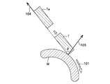
図1は、突き加工における加工面が凸形状である場合におけるワークと切削工具の位置関係を示す図であり、図1(a)は、切削工具とワークの位置関係を示す斜視図、図1(b)は、図1(a)におけるA−A’矢視断面図である。なお、ワークW、切削工具T、矢印などの名称、符号についての基本的な構成は、図1、図4から図9において、共通するため、共通する要素については同一の符号を付して説明を省略することとする。
First, the definition of each term used in the following embodiments will be described with reference to FIG.
FIG. 1 is a diagram illustrating a positional relationship between a workpiece and a cutting tool when a processing surface in a thrusting process is a convex shape, and FIG. 1A is a perspective view illustrating a positional relationship between the cutting tool and the workpiece. (B) is AA 'arrow sectional drawing in Fig.1 (a). In addition, since the basic structure about the name and code | symbols, such as the workpiece | work W, the cutting tool T, and an arrow, is common in FIG. 1, FIG. 4-9, it attaches | subjects and demonstrates the same code | symbol about a common element. Will be omitted.
図1に示すように、本実施形態において、ワークWは表が凸形状、裏が凹形状となっている。そして、切削工具Tは略円柱状であり、底面の周囲に丸みを設け、外周と底面にそれぞれ図示しない刃を設けたコーナRエンドミルである。
ここで、凹形状とは、切削工具Tが接している加工面が切削工具Tに対してくぼんでいることであり、凸形状とは、切削工具Tが接している加工面が切削工具Tに対してふくれあがっていることである。
矢印101は、切削工具Tの進行方向を示す。切削点とは、切削加工時における切削工具TとワークWの接触点であり、図1(b)においては符号102の部分である。本実施形態において、法線ベクトル103は、加工面上の切削点102における法線ベクトルを指すこととする。工具主軸方向ベクトル104は、切削工具Tの主軸方向を示すベクトルであり、本実施形態では、切削点102を含むこととする。傾斜角度θは、法線ベクトル103と工具主軸方向ベクトル104のなす角とし、法線ベクトル103と工具主軸方向ベクトル104が一致するとき、傾斜角度0°とする。定義から明らかなように、傾斜角度θを工具主軸方向ベクトル104に変換することが可能である。さらに、本実施形態では、全ての角度は切削工具Tの進行方向101と逆方向を正とする。例えば、図1(b)における傾斜角度θは、正の値を持つ。また、法線ベクトル103と90°または−90°の関係にある線を接線とよぶこととする(図示せず)。なお、これらの用語を使って突き加工を定義すると、突き加工とは、切削加工時における切削工具Tの傾斜角度が0°以上である加工と定義できる。
As shown in FIG. 1, in the present embodiment, the workpiece W has a convex shape on the front side and a concave shape on the back side. The cutting tool T is a corner R end mill having a substantially cylindrical shape, provided with roundness around the bottom surface, and provided with blades (not shown) on the outer periphery and the bottom surface, respectively.
Here, the concave shape means that the machining surface in contact with the cutting tool T is recessed with respect to the cutting tool T, and the convex shape means that the machining surface in contact with the cutting tool T is in the cutting tool T. In contrast, it is rising.
An
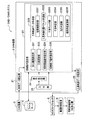
図2は、本発明の実施形態に係るCAM装置を含んで構成されるCAD/CAMシステムのブロック図である。
図2に示すCAD/CAMシステム1は、製品の形状データを作成するCAD装置3、切削工具の寸法に関するデータなどを格納するファイルサーバ4、CAD装置3で作成されたワークの形状データ(以下、形状データという)を読み込み、読みこんだ形状データを基に工具軌跡データを算出し、算出した工具軌跡データをNCポストプロセッサ5に送るCAM装置2、CAM装置2から送られた工具軌跡データを同時多軸制御NC加工機7の座標系に変換し、数値制御用のNCデータに変換するNCポストプロセッサ5、そのNCデータに従って同時多軸制御NC加工機7の直線送り軸や回転軸の動作指令を作成し、同時多軸制御NC加工機7を動作させる数値制御装置6、数値制御装置6が作成した直線送り軸や回転軸の動作指令に従って動作し、ワークWの切削加工を行う同時多軸制御NC加工機7を含んで構成される。
FIG. 2 is a block diagram of a CAD / CAM system including a CAM device according to an embodiment of the present invention.
The CAD / CAM system 1 shown in FIG. 2 includes a CAD device 3 that creates product shape data, a
(CAM装置)
さらに、CAM装置2は、CAD装置3で作成された形状データを読みこむ形状データ読込部21、読み込んだ形状データを基に、工具軌跡データを作成する切削動作設定部22、工具軌跡データを作成する際の様々な条件などを入力する入力部23、入力部23から入力された条件を基に、後記する切削動作設定部22に含まれる各部の動作を選択する操作指定部24、作成された工具軌跡データをNCポストプロセッサ5へ送る工具軌跡データ転送部25を含んで構成される。
(CAM device)
Further, the CAM device 2 creates a shape
なお、CAM装置2、CAD装置3、およびファイルサーバ4は、CPU(Central Processing Unit)、RAM(Random Access Memory)、ROM(Read Only Memory)、ハードディスクドライブ、入出力インターフェースなどを含んで構成されるコンピュータを用いて具現され、CAM装置2、CAD装置3、およびファイルサーバ4の各部は、このコンピュータのハードディスクドライブに格納されたプログラムをRAMに展開し、CPUが実行することで具現される。
The CAM device 2, the CAD device 3, and the
(切削動作設定部)
さらに、切削動作設定部22は、入力部23を介した加工部位の指定に従って形状データから切削加工する部位を選択する加工範囲設定部221、切削加工に用いる切削工具を設定し、設定した切削工具の寸法などに関するデータをファイルサーバ4から取得し、取得した切削工具の寸法などに関するデータを後記する工具軌跡データ作成部223の干渉チェック部2233へ送る工具設定部222、工具軌跡を作成する工具軌跡データ作成部223、切削工具の切削開始動作を設定する切削開始動作設定部224、切削工具の終了動作を設定する切削終了動作設定部225を少なくとも含んで構成されている。
(Cutting operation setting part)
Further, the cutting
(工具軌跡データ作成部)
工具軌跡データ作成部223は、傾斜角度の初期値を設定する初期値設定部2231、形状データ読込部21から形状データを取得し、この形状データを基に工具先端位置ベクトルを作成する工具先端位置ベクトル作成部2232、工具先端位置ベクトル作成部2232が作成した工具先端位置ベクトル上の任意の複数の点について、切削工具とワークの干渉が生じているか否かをチェックし、干渉が生じている場合はフラグをたてる干渉チェック部2233、干渉チェック部2233による干渉チェックの結果、フラグがたったか否かを判定する干渉判定部2234、加工面の凹凸を判定する凹凸判定部2235、傾斜角度を変更する傾斜角度変更部2236を含んで構成される。
(Tool path data creation part)
The tool trajectory
(CAD/CAMシステムの処理の概要)
次に、図2を参照して、本発明に係るCAM装置2を含んで構成されるCAD/CAMシステム1の処理の概要を説明する。
CAD装置3で作成された形状データは、CAM装置2の形状データ読込部21に送られ、さらに切削動作設定部22に送られる。切削動作設定部22では、送られた工具軌跡データなどを基に、工具軌跡データを作成する。具体的には、切削動作設定部22は、以下に記述する各手順によって工具軌跡データを作成する。
(Outline of CAD / CAM system processing)
Next, with reference to FIG. 2, an outline of processing of the CAD / CAM system 1 including the CAM device 2 according to the present invention will be described.
The shape data created by the CAD device 3 is sent to the shape
加工範囲設定部221は、入力部23を介して、入力される加工部位の指定に従って形状データから切削加工する部位を選択する。工具設定部222は、入力部23を介した切削工具の設定によって、ファイルサーバ4に格納されている切削加工に用いる切削工具の寸法に関するデータを選択する。さらに、工具設定部222は、選択した切削工具の寸法などに関するデータをファイルサーバ4から取得し、取得した切削工具の寸法などに関するデータを工具軌跡データ作成部223、具体的には後記する干渉チェック部2233へ送る。工具軌跡データ作成部223は、工具軌跡データを作成する。切削開始動作設定部224は、工具軌跡の切削開始動作を設定し、切削終了動作設定部225は、工具軌跡の終了動作を設定する。
The machining range setting unit 221 selects a part to be cut from the shape data according to the input designation of the machining part via the
これらの各設定部の内、加工範囲設定部221、工具設定部222、切削終了動作設定部225の処理の順番は自由である。そのため、これらの設定部で行われる処理は、入力部23を介して入力された情報を基に、操作指定部24が処理する設定部を選択し、処理が行われる。ここで、入力部23を介して入力された情報を基に、操作指定部24が処理する設定部を選択するとは、例えば、CAM装置2に接続された図示しないディスプレイ上に加工範囲設定、工具設定、工具軌跡データ作成、切削開始動作設定、切削終了動作設定などの項目が表示され、図示しない操作者が、これらを図示しないカーソルなどで選択することによって、設定部の処理を選択する、などである。しかし、工具軌跡データ作成部223の処理は、少なくとも加工範囲設定部221、工具設定部222の処理が終了した後に、処理をしなければならない。そのため、工具軌跡データ作成部223の処理は、加工範囲設定部221、工具設定部222の処理が終了した後に操作指定部24が工具軌跡データ作成部223の処理を選択することが可能となる。ここで、加工範囲設定部221、工具設定部222の処理が終了した後に操作指定部24が工具軌跡データ作成部223の処理を選択することが可能となるとは、例えば、最初、前記したディスプレイ上において、工具軌跡データ作成の項目は、選択が不可能な状態にあるが、加工範囲設定部221、工具設定部222の処理が終了した後、前記したディスプレイ上において、工具軌跡データ作成の項目が選択可能となるように表示する、などである。また、切削開始動作設定部224の処理は、少なくとも工具軌跡データ作成部223の処理が終了した後に、処理をしなければならない。そのため、切削開始動作設定部224の処理は、工具軌跡データ作成部223の処理が終了した後に操作指定部24が、前記したディスプレイ上において、切削開始動作設定の項目を選択することが可能となるように表示する。
Among these setting units, the processing range setting unit 221, the tool setting unit 222, and the cutting end operation setting unit 225 can be processed in any order. Therefore, the processing performed by these setting units is performed by selecting a setting unit to be processed by the
切削動作設定部22が作成した工具軌跡データは、工具軌跡データ転送部25へ送られ、さらに、NCポストプロセッサ5へ送られる。NCポストプロセッサ5は、その工具軌跡データを同時多軸制御NC加工機7の座標系に変換し、数値制御装置6用のNCデータに変換する。数値制御装置6は、そのNCデータに従って同時多軸制御NC加工機7の直線送り軸や回転軸の動作指令を作成し、同時多軸制御NC加工機7を動作させる。
The tool trajectory data created by the cutting
次に、本発明の実施形態に係る工具軌跡データ作成部の突き加工用の工具軌跡データの作成の処理について、図1、図2を参照しつつ、図3に沿って説明する。
図3は、突き加工用の工具軌跡データの作成の処理の流れを示すフローである。なお、本実施形態では、切削工具TにコーナRエンドミルを選択した場合について示すが、これに限らず他の回転工具を選択してもよい。なお、本実施形態における工具軌跡データは、荒加工だけでなく、例えば中仕上げや仕上げ加工を行うための切削加工に用いる工具軌跡データとすることもできる。
Next, the process of creating tool path data for piercing by the tool path data generating unit according to the embodiment of the present invention will be described with reference to FIGS.
FIG. 3 is a flowchart showing a flow of processing for creating tool path data for piercing. In addition, in this embodiment, although shown about the case where a corner R end mill is selected as the cutting tool T, you may select not only this but another rotary tool. The tool trajectory data in the present embodiment can be not only rough machining but also tool trajectory data used for cutting for performing, for example, intermediate finishing or finishing.
まず、切削工具Tの傾斜角度の初期値が、初期値設定部2231において設定される(S31)。このとき、傾斜角度の初期値を入力部23を介して設定してもよいし、またファイルサーバ4に、加工面の凹凸、加工面の曲率に対応した傾斜角度の初期値をテーブルとして予め格納しておき、初期値設定部2231が加工面の凹凸、加工面の曲率を判別して、その凹凸、曲率に対応した傾斜角度の初期値をファイルサーバ4から取得してもよい。本実施形態では、傾斜角度の初期値は90°、すなわち進行方向101に対し、後方の接線方向に工具主軸方向ベクトル104を合わせるよう固定して設定されているものとする。
First, the initial value of the inclination angle of the cutting tool T is set in the initial value setting unit 2231 (S31). At this time, the initial value of the tilt angle may be set via the
次に、初期値設定部2231は、傾斜角度の初期値を、工具主軸方向ベクトルに変換し工具先端位置ベクトル作成部2232に送る。工具先端位置ベクトル作成部2232は、形状データ読込部21から形状データを取得する。さらに、工具先端位置ベクトル作成部2232は、工具設定部222から、選択した切削工具の寸法などに関するデータを取得する。工具先端位置ベクトル作成部2232は、取得した形状データ、工具主軸方向ベクトルと選択した切削工具の寸法などに関するデータとを基に、工具先端位置ベクトルを作成し(S32)、工具主軸方向ベクトル、作成した工具先端位置ベクトル、形状データと切削工具の寸法などに関するデータとを干渉チェック部2233へ送る。
Next, the initial
次に、干渉チェック部2233は、作成した工具先端位置ベクトルについて、形状データと工具先端位置ベクトル、工具の寸法などに関するデータを基に、切削工具TとワークWとが干渉するか否かのチェックを行う(S33)。具体的な干渉チェックの方法としては、例えば、沖野 教郎 著、自動設計の方法論、昭和57年5月30日、pp.146-148に記載されている方法がある。干渉チェック部2233は、干渉が生じる箇所が存在する場合に、その箇所における工具先端位置ベクトルにフラグをたてる。具体的には、例えば、工具先端位置ベクトルと、フラグは常に対のデータとして記憶されており、干渉が生じていない箇所の工具先端位置ベクトルには、0が対のデータとして記憶され、干渉が生じている箇所の工具先端位置ベクトルには、1が対のデータとして記憶されるなどである。次に、干渉チェック部2233は、工具主軸方向ベクトルと、工具先端位置ベクトル、形状データ、切削工具の寸法などに関するデータ、およびフラグを干渉判定部2234へ送る。
Next, the
干渉判定部2234は、ステップS33の結果において、フラグがたっているか否かを判定する(S34)。干渉する箇所が存在しない場合(S34→干渉箇所なし)、処理を終了、すなわち工具軌跡データの作成を終了し、干渉判定部2234は、作成した工具軌跡データ、すなわち工具主軸方向ベクトルと工具先端位置ベクトルを工具軌跡データ転送部25へ送る。干渉する箇所が存在する場合、すなわちフラグのデータに1が存在する場合(S34→干渉箇所あり)、干渉判定部2234は、工具主軸方向ベクトル、工具先端位置ベクトル、形状データ、切削工具の寸法などに関するデータを凹凸判定部2235へ送り、ステップS35へ処理を進める。
The
ステップS35において、凹凸判定部2235が、送られた形状データと入力部23を介して入力された情報を基に、加工面の凹凸を判定する。ここで、入力部23を介して入力される情報を基に、加工面の凹凸を判定するとは、例えば図示しない操作者が、加工面の凹凸を判定し、その判定結果を入力部23を介して凹凸判定部2235へ送り、凹凸判定部2235は、送られた情報を基に凹凸を判定する、などである。加工面が凹形状だった場合(S35→凹)、ステップS36へ処理を進める。加工面が凸形状だった場合(S35→凸)、ステップS37へ処理を進める。いずれの処理へ進む場合でも、凹凸判定部2235は、工具主軸方向ベクトル、工具先端位置ベクトル、形状データ、切削工具の寸法などに関するデータを傾斜角度変更部2236へ送る。
In step S <b> 35, the unevenness determination unit 2235 determines the unevenness of the processed surface based on the sent shape data and information input via the
ステップS36では、傾斜角度変更部2236が、後記するθaからθbの範囲で、傾斜角度θを予め設定しておいた所定角度だけ小さくすることによって、傾斜角度θの変更がなされる。傾斜角度θの変更における角度の範囲(θa,θb)の算出については後に詳述する。このような角度範囲とすることで、突き加工の状態を保持したまま、傾斜角度θの変更を行うことができる。 In step S36, the inclination angle changing unit 2236 changes the inclination angle θ by reducing the inclination angle θ by a predetermined angle within a range of θ a to θ b described later. The calculation of the angle ranges (θ a , θ b ) in changing the tilt angle θ will be described in detail later. By setting it as such an angle range, it is possible to change the inclination angle θ while maintaining the state of piercing.
ステップS37では、傾斜角度変更部2236が、0°から90°の範囲で、傾斜角度θを予め設定しておいた所定角度だけ小さくすることによって、傾斜角度θの変更がなされる。傾斜角度θの変更における角度の範囲(0°,90°)の算出については後に詳述する。このような角度範囲とすることで、突き加工の状態を保持したまま、傾斜角度θの変更を行うことができる。 In step S37, the tilt angle θ is changed by the tilt angle changing unit 2236 by reducing the tilt angle θ by a predetermined angle within a range of 0 ° to 90 °. The calculation of the angle range (0 °, 90 °) in changing the tilt angle θ will be described in detail later. By setting it as such an angle range, it is possible to change the inclination angle θ while maintaining the state of piercing.
ステップS36、またはステップS37における傾斜角度θの変更後、傾斜角度変更部2236は、変更した傾斜角度θを工具主軸方向ベクトルに変換し、工具主軸方向ベクトルを工具先端位置ベクトル作成部2232へ送り、ステップS32の処理へ戻る。 After changing the tilt angle θ in step S36 or step S37, the tilt angle changing unit 2236 converts the changed tilt angle θ into a tool spindle direction vector, and sends the tool spindle direction vector to the tool tip position vector creating unit 2232. The process returns to step S32.
次に、図3のステップS36およびステップS37の、傾斜角度変更の処理における傾斜角度の範囲の設定方法について、図4から図5を参照して説明する。なお、以下の図において、図を見易くするため、コーナRエンドミルの底面の周囲の丸みは図示しないこととする。また、図4、および図5における演算は、全て形状データと、切削工具の寸法などに関するデータを基に行われる。 Next, a method for setting the tilt angle range in the tilt angle change process in steps S36 and S37 in FIG. 3 will be described with reference to FIGS. In the following figures, the roundness around the bottom surface of the corner R end mill is not shown in order to make the figures easy to see. The calculations in FIGS. 4 and 5 are all performed based on the shape data and data relating to the dimensions of the cutting tool.
(加工面が凹形状の場合における傾斜角度の範囲)
まず、図4を参照して、加工面が凹形状のときの、図3のステップS36の傾斜角度変更の処理における傾斜角度の範囲の設定について説明する。
図4は、加工面が凹形状のときの、図3のステップS36の傾斜角度変更の処理における傾斜角度の範囲の設定方法を示す図である。図4におけるワークWは、図1(a)におけるA−A’矢視断面図である。
加工面が凹形状の場合は、図4(a)に示すように、進行方向101に対し前方に切削工具Tを傾斜させていき、やがて切削点102以外の切削工具Tの底面とワークWが接触する点(第1の接触点401)を求め、このときの傾斜角度(第1の傾斜角度θa)を求める。
図4(b)に示すように、切削工具Tの傾斜角度θが第1の傾斜角度θa以下となると、切削工具Tの底面とワークWが干渉し、削り込みが発生する。
次に、図4(c)に示すように、進行方向101に対して後方に切削工具Tを傾斜させていき、やがて切削点102以外の切削工具Tの側面とワークWが接触する点(第2の接触点402)を求め、このときの傾斜角度(第2の傾斜角度θb)を求める。
図4(d)に示すように、切削工具Tの傾斜角度θが第2の傾斜角度θb以上になると、切削工具Tの側面とワークWが干渉し、削り込みが発生する。
よって、加工面が凹形状の場合、図4(e)に示すように、傾斜角度θは第1の傾斜角度θa以上、第2の傾斜角度θb以下でなければならない。
これら傾斜角度θの範囲の算出は、工具軌跡上の任意の点において演算してもよいし、切削開始点において演算してもよい。
このような角度範囲とすることで、突き加工の状態を保持したまま、傾斜角度θの変更を行うことができる。
(Inclination angle range when the machining surface is concave)
First, with reference to FIG. 4, the setting of the range of the tilt angle in the process of changing the tilt angle in step S36 of FIG. 3 when the processing surface is concave will be described.
FIG. 4 is a diagram illustrating a method of setting the range of the tilt angle in the process of changing the tilt angle in step S36 of FIG. 3 when the processed surface is concave. A workpiece W in FIG. 4 is a cross-sectional view taken along the line AA ′ in FIG.
When the processing surface is concave, as shown in FIG. 4A, the cutting tool T is inclined forward with respect to the traveling
As shown in FIG. 4 (b), when the inclination angle theta of the cutting tool T is equal to or less than the first tilt angle theta a, bottom and workpiece W of the cutting tool T interferes, narrowing cutting occurs.
Next, as shown in FIG. 4C, the cutting tool T is inclined backward with respect to the traveling
As shown in FIG. 4D, when the inclination angle θ of the cutting tool T becomes equal to or larger than the second inclination angle θ b , the side surface of the cutting tool T and the workpiece W interfere with each other to cause cutting.
Therefore, the machined surface is the case of concave, as shown in FIG. 4 (e), the inclination angle theta is the first tilt angle theta a higher, must be less than or equal to the second inclination angle theta b.
The calculation of the range of the inclination angle θ may be performed at an arbitrary point on the tool path or may be performed at a cutting start point.
By setting it as such an angle range, it is possible to change the inclination angle θ while maintaining the state of piercing.
(加工面が凸形状の場合における傾斜角度の範囲)
次に、図5を参照して、加工面が凸形状のときの、図3のステップS37の傾斜角度変更の処理における傾斜角度の範囲の設定について説明する。
図5は、加工面が凸形状のときの、図3のステップS37の傾斜角度変更の処理における傾斜角度の範囲の設定方法を示す図であり、図1(a)におけるA−A’矢視断面図を示している。
加工面が凸形状の場合は、図5(a)に示すように、進行方向に対し前方に切削工具Tを傾斜させていき、やがて切削点以外の切削工具Tの底面とワークWが接触する点を求め、このときの傾斜角度(第3の傾斜角度θc)を求める。このとき、切削工具Tの底面は、切削点102における接平面と一致する。よって、本実施形態における第3の傾斜角度θcは、0°である。
図5(b)に示すように、切削工具Tの傾斜角度θが0°以下となると、切削工具Tの底面とワークWが干渉し、削り込みが発生する。
次に、図5(c)に示すように、進行方向に対して後方に切削工具Tを傾斜させていき、やがて切削点以外の切削工具Tの側面とワークWが接触する点を求め、このときの傾斜角度(第4の傾斜角度θd)を求める。このときの工具主軸方向ベクトル104は、切削点102における接線と一致する。よって、本実施形態における第4の傾斜角度θdは、90°である。
図5(d)に示すように、切削工具Tの傾斜角度θが90°以上になると、切削工具Tの側面とワークWが干渉し、削り込みが発生する。
よって、コーナRエンドミルを用いた切削加工において、加工面が凸形状の場合、図5(e)に示すように、傾斜角度θは0°以上、90°以下でなければならない。
これら傾斜角度θの範囲の算出は、工具軌跡上の任意の点において演算してもよいし、切削開始点において演算してもよい。
このような角度範囲とすることで、突き加工の状態を保持したまま、傾斜角度θの変更を行うことができる。
(Inclination angle range when the machining surface is convex)
Next, with reference to FIG. 5, the setting of the range of the tilt angle in the process of changing the tilt angle in step S37 of FIG. 3 when the processed surface is convex will be described.
FIG. 5 is a diagram showing a method of setting the range of the tilt angle in the process of changing the tilt angle in step S37 in FIG. A cross-sectional view is shown.
When the processing surface is convex, as shown in FIG. 5A, the cutting tool T is inclined forward with respect to the traveling direction, and the work W comes into contact with the bottom surface of the cutting tool T other than the cutting point. A point is obtained, and the inclination angle (third inclination angle θ c ) at this time is obtained. At this time, the bottom surface of the cutting tool T coincides with the tangential plane at the
As shown in FIG. 5B, when the inclination angle θ of the cutting tool T is 0 ° or less, the bottom surface of the cutting tool T and the workpiece W interfere with each other, and cutting occurs.
Next, as shown in FIG. 5 (c), the cutting tool T is inclined backward with respect to the traveling direction, and the point where the side surface of the cutting tool T other than the cutting point comes into contact with the workpiece W is obtained. To obtain the tilt angle (fourth tilt angle θ d ). The tool
As shown in FIG. 5D, when the inclination angle θ of the cutting tool T is 90 ° or more, the side surface of the cutting tool T and the workpiece W interfere with each other, and cutting occurs.
Therefore, in the cutting process using the corner R end mill, when the processing surface is convex, the inclination angle θ must be 0 ° or more and 90 ° or less as shown in FIG.
The calculation of the range of the inclination angle θ may be performed at an arbitrary point on the tool path or may be performed at a cutting start point.
By setting it as such an angle range, it is possible to change the inclination angle θ while maintaining the state of piercing.
次に、図2、図3を参照しつつ、図6を参照して、本発明の実施形態に係る切削開始動作設定部において設定される切削工具の動作について説明する。
図6は、本発明の実施形態に係る切削開始動作設定部において設定される切削工具の動作を示す図である。
同時多軸制御NC加工機7が、工具軌跡データ作成部223で作成された工具軌跡データを基に実際の切削加工に入る際、切削工具Tは、空回しの状態から、急にワークWの切削へ入るため、最初の切削に入る前の動作を考慮しないと切削負荷が急激に増大する。その結果、ワークWの変形、切削工具Tの破損などの問題が生じるおそれがある。
本実施形態では、切削開始動作設定部224は、最初の切削位置における工具主軸方向から切削工具Tを侵入できるよう、切削工具Tを工具主軸方向に移動した位置(Ta)に切削開始位置を設定する。このときの工具主軸方向ベクトル104は、図3のステップS36、ステップS37において、工具軌跡データ作成部223が設定した傾斜角度θから変換されたものである。このように設定することで、斜め方向から切削工具TがワークWに侵入するため、切削加工に入る際の切削工具Tに対する切削抵抗を軽減することができる。この結果、切削工具Tの切削開始時における横ブレや切削工具Tの破損を防ぐことができる。
Next, the operation of the cutting tool set in the cutting start operation setting unit according to the embodiment of the present invention will be described with reference to FIGS. 2 and 3 and FIG.
FIG. 6 is a diagram illustrating the operation of the cutting tool set in the cutting start operation setting unit according to the embodiment of the present invention.
When the simultaneous multi-axis control NC machine 7 enters actual cutting based on the tool path data created by the tool path
In the present embodiment, the cutting start operation setting unit 224 sets the cutting start position at a position (Ta) where the cutting tool T is moved in the tool spindle direction so that the cutting tool T can enter from the tool spindle direction at the first cutting position. To do. The tool
次に、図2、図3を参照しつつ、図7を参照して、本発明の実施形態に係る切削終了動作設定部において設定される切削工具の動作について説明する。
図7は、本発明の実施形態に係る切削終了動作設定部において設定される切削工具の動作を示す図である。
同時多軸制御NC加工機7が、工具軌跡データ作成部223で作成された工具軌跡データを基に実際の切削加工を終了する際、切削状態から急に空回りの状態となるため、切削負荷の急激な変化が生じたり、時にはワークWと切削工具Tの側面が干渉してしまう。その結果、切削工具Tを固定している図示しないホルダから、切削工具Tが脱落してしまうといった問題が生じるおそれがある。
本実施形態では、切削終了動作設定部225は、図7に示すように、最後の切削点102aから、例えば法線方向に中心Cを有する円弧上701を、切削工具Tの進行方向に沿って移動させ(T→Tb)切削工具Tを移動させ終了させるよう設定する。このように設定することで、ワークWと切削工具Tとが徐々に離れるように設定できるため、切削終了時のワークWと切削工具Tの干渉や、切削負荷の急激な変化を軽減することができる。
Next, the operation of the cutting tool set in the cutting end operation setting unit according to the embodiment of the present invention will be described with reference to FIGS. 2 and 3 and FIG.
FIG. 7 is a diagram illustrating an operation of the cutting tool set in the cutting end operation setting unit according to the embodiment of the present invention.
When the simultaneous multi-axis control NC machine 7 finishes the actual cutting process based on the tool path data created by the tool path
In the present embodiment, as shown in FIG. 7, the cutting end operation setting unit 225 extends from the
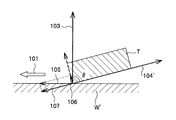
前記した従来手法を説明した図9を参照しつつ、図8を参照して切削加工に突き加工を適用したときの作用を説明する。
図8は、工具主軸方向ベクトルを、切削工具の進行方向に対し、後方に傾けて設定した状態を示した図である。
図9に示すように、切削工具Tを進行方向101に対し前方に傾けた場合、切削工具Tの進行方向101と同方向、かつワークWの法線ベクトル103に対し、垂直方向に切削力105が生じる。この切削力105は、工具主軸方向104’に垂直な成分(工具主軸垂直方向成分)106と、工具主軸方向成分107に分解できる。工具主軸垂直方向成分106は、工具主軸方向成分107に対して大きいことから、切削工具Tの工具主軸垂直方向成分106に大きな力が加わる。切削工具Tは、工具主軸垂直方向成分106が、工具主軸方向104’に比べて剛性が小さいため、工具主軸垂直方向成分106に大きな力が生じると、切削工具Tが振動しやすくなる。
一方、図8に示すように本発明による工具主軸方向ベクトルの定め方に従った突き加工では、工具主軸垂直方向成分106は工具主軸方向成分107に対して小さいことから、切削工具Tの工具主軸方向104’に大きな力が加わる。切削工具Tは、工具主軸方向104’が工具主軸垂直方向成分106に比べて剛性が大きいため、工具主軸方向104’に大きな力が生じても、切削工具Tが振動しにくくなる。また、剛性が大きい工具主軸方向104’に大きな力が働くため、より高い切削負荷に耐えることができる。
以上の結果より、突き加工を適用した切削加工では、加工速度を上げることに伴う切削抵抗の増大が原因となって生じる振動発生、ワーク変形を抑えることができ、高効率な切削加工が可能となる。
With reference to FIG. 9 describing the above-described conventional technique, the operation when the butt process is applied to the cutting process will be described with reference to FIG.
FIG. 8 is a diagram illustrating a state in which the tool spindle direction vector is set to be tilted rearward with respect to the traveling direction of the cutting tool.
As shown in FIG. 9, when the cutting tool T is tilted forward with respect to the traveling
On the other hand, in the piercing according to the method of determining the tool spindle direction vector according to the present invention as shown in FIG. 8, the tool spindle
From the above results, in cutting processing using thrusting, vibration generation and workpiece deformation caused by an increase in cutting resistance accompanying an increase in processing speed can be suppressed, enabling highly efficient cutting. Become.
以上、本発明の実施形態について説明したが、本発明は前記した実施形態に限定されることなく適宜変形して実施することが可能である。
例えば、本実施形態では切削工具Tとして、コーナRエンドミルを選択したことを前提としているが、その他の回転切削工具を選択することも可能である。この場合、図4から図5における第1の傾斜角度から第4の傾斜角度θa,θb,θc,θdは、それぞれの回転切削工具の寸法などに関するデータと、形状データを基に算出した角度とすることで、同様の処理を行うことができる。
Although the embodiment of the present invention has been described above, the present invention is not limited to the above-described embodiment, and can be appropriately modified and implemented.
For example, in the present embodiment, it is assumed that a corner R end mill is selected as the cutting tool T, but other rotary cutting tools can also be selected. In this case, the first to fourth inclination angles θ a , θ b , θ c , and θ d in FIGS. 4 to 5 are based on the data regarding the dimensions of the respective rotary cutting tools and the shape data. By using the calculated angle, the same processing can be performed.
また、本実施形態では、切削終了動作設定部225における切削動作終了時の切削工具Tの動きについて、円弧状かつ下方としたが、これに限らず円弧状かつ上方、円弧状かつ横方向などとしてもよい。また、円弧状に限らず、他の曲線状であってもよい。 Further, in the present embodiment, the movement of the cutting tool T at the end of the cutting operation in the cutting end operation setting unit 225 is arcuate and downward, but is not limited thereto, and is not limited to this. Also good. Moreover, it is not limited to the arc shape, but may be another curved shape.
また、本実施形態では、図2の工具設定部222は、入力部23を介した切削工具Tの設定によって、ファイルサーバ4に格納されている切削加工に用いる切削工具Tの寸法に関するデータを選択、取得し、干渉チェック部2233へ送っているが、これに限らず、例えば工具設定部222は、入力部23を介して、切削工具Tの選択を行い、選択した切削工具の名称などを干渉チェック部2233へ送り、干渉チェック部2233は送られた切削工具の名称などを基に、ファイルサーバ4から選択された切削工具の寸法などに関するデータを取得してもよい。
Further, in the present embodiment, the tool setting unit 222 in FIG. 2 selects data related to the size of the cutting tool T used for cutting stored in the
さらに、本実施形態では図2の凹凸判定部2235は、図2の入力部23を介して取得した情報をもとに、加工面の凹凸を判定したが、これに限らず、例えば凹凸判定部2235が加工面の微分係数などを解析することによって、加工面の凹凸を自動的に判定してもよい。
Furthermore, in this embodiment, the unevenness determination unit 2235 in FIG. 2 determines the unevenness of the processed surface based on the information acquired via the
また、図2のファイルサーバ4をデータベースにしてもよい。このとき、データベースはCAD装置3やCAM装置2と別体にしてもよいし、CAD装置3と一体にする、もしくはCAM装置2と一体にしてもよい。
Further, the
2 CAM装置
3 CAD装置
4 ファイルサーバ
21 形状データ読込部
22 切削動作設定部
23 入力部
24 操作指定部
25 工具軌跡データ転送部
101 進行方向
102,102a 切削点
103 法線ベクトル
104,104’ 工具主軸方向ベクトル
221 加工範囲設定部
222 工具設定部
223 工具軌跡データ作成部
224 切削開始動作設定部
225 切削終了動作設定部
2231 初期値設定部
2232 工具先端位置ベクトル作成部
2233 干渉チェック部
2234 干渉判定部
2235 凹凸判定部
2236 傾斜角度変更部
θ,θ’ 傾斜角度
T,Ta,Tb 切削工具
W,W’ ワーク
DESCRIPTION OF SYMBOLS 2 CAM apparatus 3
Claims (5)
込手段と、
各種の切削工具の形状に関する情報が格納された記憶手段と、
前記切削工具の種類を選択し、選択した前記切削工具の形状に関する情報を前記記憶手段から取得する工具設定手段と、
工具軌跡データを作成する工具軌跡データ作成手段と、
を含んで構成され、加工対象物の中仕上げ加工および表面仕上げ加工を行うためのCAM装置であって、
前記工具軌跡データ作成手段は、
前記形状データ読込手段から前記形状データを取得し、前記工具設定手段から前記選択した切削工具の形状に関する情報を取得し、
前記切削工具の角度の初期値を、前記切削工具の進行方向後方の接線方向に当該切削工具の主軸方向を示す工具主軸方向ベクトルを合わせるように設定し、
前記切削工具の角度が初期値の状態で、前記形状データおよび前記切削工具の形状に関する情報を基に、前記工具主軸方向ベクトルを含む工具軌跡データを作成し、
前記工具軌跡データと、前記形状データと、前記切削工具の形状に関する情報と、を基に、前記切削工具と、前記加工対象物と、が干渉するか否かの干渉チェックを行い、
前記干渉チェックの結果、前記切削工具と、前記加工対象物と、が干渉しないと判定された場合、前記工具軌跡データを出力し、
前記干渉チェックの結果、前記切削工具と、前記加工対象物と、が干渉する箇所があると判定された場合、前記形状データを基に、切削加工面の微分係数を算出し、解析することによって、前記切削加工面の凹凸を判定し、
前記判定の結果、前記切削加工面が凹面である場合、前記取得した形状データと前記選択した切削工具の形状に関する情報とを使用して、前記切削工具を進路方向に対し、後方に傾斜させた状態における切削点を中心として、前記切削工具を仮想的に前後に傾斜させ、前記切削工具の底面および側面が前記加工対象物に接触する際の前記切削加工面に対する前記切削工具の角度である第1の傾斜角度および第2の傾斜角度を算出し、
前記第1の傾斜角度および前記第2の傾斜角度の範囲内で、第3の傾斜角度を決定し、
前記判定の結果、前記切削加工面が凸面である場合、前記取得した前記形状データと前記選択した切削工具の形状に関する情報とを使用して、前記切削加工面に対する前記切削工具の角度が、0°から、進路方向に対して後方90°の範囲内で、前記工具主軸方向ベクトルを後方90°に近づけるように、前記第3の傾斜角度を決定し、
前記決定した第3の傾斜角度を基に、前記工具主軸方向ベクトルを含む工具軌跡データを作成し、
工具進行方向の切削力を、工具主軸方向の力と、工具主軸に対して垂直方向の力と、に分解したとき前記工具主軸方向の力より、工具主軸に対して垂直方向の力が小さくなるよう、前記第3の角度を決定すること
を特徴とするCAM装置。 A shape data reading means for reading shape data of a processing object having a curved surface, created by a CAD device;
Storage means for storing information on the shapes of various cutting tools;
A tool setting unit that selects a type of the cutting tool and acquires information on the shape of the selected cutting tool from the storage unit;
Tool path data creating means for creating tool path data;
A CAM device for performing intermediate finishing and surface finishing of a workpiece,
The tool trajectory data creation means includes
Obtaining the shape data from the shape data reading means, obtaining information on the shape of the selected cutting tool from the tool setting means,
The initial value of the angle of the cutting tool is set so that a tool spindle direction vector indicating the spindle direction of the cutting tool is aligned with the tangential direction behind the cutting tool in the traveling direction,
In a state where the angle of the cutting tool is an initial value, based on the shape data and information on the shape of the cutting tool, create tool trajectory data including the tool spindle direction vector,
Based on the tool trajectory data, the shape data, and information on the shape of the cutting tool, an interference check is performed to determine whether or not the cutting tool and the object to be processed interfere with each other.
As a result of the interference check, when it is determined that the cutting tool and the workpiece do not interfere with each other, the tool trajectory data is output,
As a result of the interference check, when it is determined that there is a portion where the cutting tool and the processing object interfere with each other , by calculating and analyzing a differential coefficient of the cutting surface based on the shape data, , Determine the unevenness of the cutting surface,
As a result of the determination, when the cutting surface is a concave surface, the cutting tool is inclined backward with respect to the course direction using the acquired shape data and information on the shape of the selected cutting tool. An angle of the cutting tool with respect to the cutting surface when the cutting tool is virtually tilted back and forth around the cutting point in the state and the bottom and side surfaces of the cutting tool are in contact with the workpiece. Calculating a tilt angle of 1 and a second tilt angle;
Determining a third tilt angle within the range of the first tilt angle and the second tilt angle;
As a result of the determination, when the cutting surface is a convex surface, the angle of the cutting tool with respect to the cutting surface is 0 using the acquired shape data and information on the shape of the selected cutting tool. The third inclination angle is determined so that the tool spindle direction vector approaches 90 ° rearward within a range of 90 ° rearward relative to the course direction from
Based on the third inclined angle of the determined, to create a tool path data including the pre-SL tool spindle direction vector,
When the cutting force in the tool advancing direction is broken down into a force in the tool spindle direction and a force in the direction perpendicular to the tool spindle, the force in the direction perpendicular to the tool spindle is smaller than the force in the tool spindle direction. The CAM device is characterized in that the third angle is determined.
前記切削工具を、前記切削加工面に対し、後方に傾斜させた状態で前記切削工具の主軸方向から前記加工対象物に侵入させるよう設定する手順を実行する切削開始動作設定手段をさらに含んで構成すること、
を特徴とする請求項1に記載のCAM装置。 The CAM device
It further includes a cutting start operation setting means for executing a procedure for setting the cutting tool so as to enter the workpiece from the main axis direction of the cutting tool in a state where the cutting tool is inclined rearward with respect to the cutting surface. To do,
The CAM device according to claim 1.
各種の切削工具の形状に関する情報が格納された記憶手段と、
前記切削工具の種類を選択し、選択した前記切削工具の形状に関する情報を前記記憶手段から取得する工具設定手段と、
工具軌跡データを作成する工具軌跡データ作成手段と、
を含んで構成され、加工対象物の中仕上げ加工および表面仕上げ加工を行うためのCAM装置における工具軌跡作成方法であって、
前記工具軌跡データ作成手段が、
前記形状データ読込手段から前記形状データを取得し、前記工具設定手段から前記選択した切削工具の形状に関する情報を取得する手順、
前記切削工具の角度が、当該切削工具の進行方向後方の接線方向に当該切削工具の主軸方向を示す工具主軸方向ベクトルを合わせるように設定された初期値の状態で、前記形状データおよび前記切削工具の形状に関する情報を基に、前記工具主軸方向ベクトルを含む工具軌跡データを作成する手順、
前記工具軌跡データと、前記形状データと、前記切削工具の形状に関する情報と、を基に、前記切削工具と、前記加工対象物と、が干渉するか否かの干渉チェックを行う手順、
前記干渉チェックの結果、前記切削工具と、前記加工対象物と、が干渉しないと判定された場合、前記工具軌跡データを出力する手順、
前記干渉チェックの結果、前記切削工具と、前記加工対象物と、が干渉する箇所があると判定された場合、前記形状データを基に、切削加工面の微分係数を算出し、解析することによって、前記切削加工面の凹凸を判定する手順、
前記判定の結果、前記切削加工面が凹面である場合、前記取得した形状データと前記選択した切削工具の形状に関する情報とを使用して、前記切削工具を進路方向に対し、後方に傾斜させた状態における切削点を中心として、前記切削工具を仮想的に前後に傾斜させ、前記切削工具の底面および側面が前記加工対象物に接触する際の前記切削加工面に対する前記切削工具の角度である第1の傾斜角度および第2の傾斜角度を算出する手順、
前記第1の傾斜角度および前記第2の傾斜角度の範囲内で、第3の傾斜角度を決定する手順、
前記判定の結果、前記切削加工面が凸面である場合、前記取得した前記形状データと前記選択した切削工具の形状に関する情報とを使用して、前記切削加工面に対する前記切削工具の角度が、0°から、進路方向に対して後方90°の範囲内で、工具進行方向の切削力を、工具主軸方向の力と、工具主軸に対して垂直方向の力と、に分解したとき前記工具主軸方向の力より、工具主軸に対して垂直方向の力が小さくなるように、かつ前記工具の主軸方向を後方90°に近づけるように、前記第3の傾斜角度を決定する手順、
前記決定した第3の傾斜角度を基に、前記工具主軸方向ベクトルを含む工具軌跡データを作成する手順、
を、含んで実行することを特徴とする工具軌跡作成方法。 A shape data reading means for reading shape data of a processing object having a curved surface, created by a CAD device;
Storage means for storing information on the shapes of various cutting tools;
A tool setting unit that selects a type of the cutting tool and acquires information on the shape of the selected cutting tool from the storage unit;
Tool path data creating means for creating tool path data;
A tool trajectory creation method in a CAM device for performing intermediate finishing and surface finishing of a workpiece,
The tool trajectory data creating means is
A procedure for obtaining the shape data from the shape data reading means and obtaining information on the shape of the selected cutting tool from the tool setting means,
The shape data and the cutting tool in the state where the angle of the cutting tool is an initial value set so as to match the tool spindle direction vector indicating the spindle direction of the cutting tool with the tangential direction behind the cutting tool in the traveling direction A procedure for creating tool path data including the tool spindle direction vector based on information on the shape of
A procedure for performing an interference check as to whether or not the cutting tool and the object to be processed interfere based on the tool trajectory data, the shape data, and information on the shape of the cutting tool,
As a result of the interference check, when it is determined that the cutting tool and the workpiece do not interfere with each other, a procedure for outputting the tool trajectory data;
As a result of the interference check, when it is determined that there is a portion where the cutting tool and the processing object interfere with each other , by calculating and analyzing a differential coefficient of the cutting surface based on the shape data, , A procedure for determining unevenness of the cut surface,
As a result of the determination, when the cutting surface is a concave surface, the cutting tool is inclined backward with respect to the course direction using the acquired shape data and information on the shape of the selected cutting tool. An angle of the cutting tool with respect to the cutting surface when the cutting tool is virtually tilted back and forth around the cutting point in the state and the bottom and side surfaces of the cutting tool are in contact with the workpiece. A procedure for calculating a tilt angle of 1 and a second tilt angle;
Determining a third tilt angle within a range of the first tilt angle and the second tilt angle;
As a result of the determination, when the cutting surface is a convex surface, the angle of the cutting tool with respect to the cutting surface is 0 using the acquired shape data and information on the shape of the selected cutting tool. When the cutting force in the tool advancing direction is decomposed into a force in the tool spindle direction and a force in the direction perpendicular to the tool spindle within a range of 90 ° rearward with respect to the path direction, the tool spindle direction A step of determining the third inclination angle so that a force perpendicular to the tool spindle is smaller than the force of the tool and the spindle direction of the tool approaches 90 ° rearward ;
Procedure on the basis of the third inclined angle of the determined, to create a tool path data including the pre-SL tool spindle direction vector,
A tool path creation method, characterized in that the run Nde free.
前記切削工具を、前記切削加工面に対し、後方に傾斜させた状態で前記切削工具の主軸方向から前記加工対象物に侵入させるよう設定する手順、
をさらに含んで実行することを特徴とする請求項3に記載の工具軌跡作成方法。 The CAM device is
A procedure for setting the cutting tool so as to enter the workpiece from the main axis direction of the cutting tool in a state where the cutting tool is inclined backward with respect to the cutting surface.
The tool path creation method according to claim 3, further comprising:
Priority Applications (1)
| Application Number | Priority Date | Filing Date | Title |
|---|---|---|---|
| JP2005046298A JP4700369B2 (en) | 2005-02-22 | 2005-02-22 | CAM device, tool path creation method, and tool path creation program |
Applications Claiming Priority (1)
| Application Number | Priority Date | Filing Date | Title |
|---|---|---|---|
| JP2005046298A JP4700369B2 (en) | 2005-02-22 | 2005-02-22 | CAM device, tool path creation method, and tool path creation program |
Publications (3)
| Publication Number | Publication Date |
|---|---|
| JP2006235764A JP2006235764A (en) | 2006-09-07 |
| JP2006235764A5 JP2006235764A5 (en) | 2007-03-01 |
| JP4700369B2 true JP4700369B2 (en) | 2011-06-15 |
Family
ID=37043372
Family Applications (1)
| Application Number | Title | Priority Date | Filing Date |
|---|---|---|---|
| JP2005046298A Expired - Fee Related JP4700369B2 (en) | 2005-02-22 | 2005-02-22 | CAM device, tool path creation method, and tool path creation program |
Country Status (1)
| Country | Link |
|---|---|
| JP (1) | JP4700369B2 (en) |
Families Citing this family (2)
| Publication number | Priority date | Publication date | Assignee | Title |
|---|---|---|---|---|
| JP5172293B2 (en) * | 2007-11-26 | 2013-03-27 | 株式会社アルゴグラフィックス | Press die machining method, machining program, machining program generation program, and machining apparatus |
| JP5161042B2 (en) * | 2008-11-12 | 2013-03-13 | 株式会社神戸製鋼所 | End mill machining method, machining program creation method and machining program creation apparatus using the same |
-
2005
- 2005-02-22 JP JP2005046298A patent/JP4700369B2/en not_active Expired - Fee Related
Also Published As
| Publication number | Publication date |
|---|---|
| JP2006235764A (en) | 2006-09-07 |
Similar Documents
| Publication | Publication Date | Title |
|---|---|---|
| CN103901818B (en) | Computer assisted manufacturing apparatus, method for product shape processing and storage medium | |
| JP5594685B2 (en) | Tool path generation device, tool path calculation method, and tool path generation program | |
| JP5890907B2 (en) | Machining process determination method and machining process design apparatus | |
| JP5881850B2 (en) | Machine tool control device and machine tool | |
| JP5911595B2 (en) | Machine tool control device and machine tool | |
| JP4700369B2 (en) | CAM device, tool path creation method, and tool path creation program | |
| JP5881843B2 (en) | Tool path generation method, machine tool control apparatus, and tool path generation apparatus | |
| JPWO2021038848A1 (en) | Manufacturing method of integrated rotor and cutting program of its blade | |
| JP2009116782A (en) | Support method and device for machining process verification, support program for machining process verification, and storage medium | |
| JP4577303B2 (en) | Tool axis attitude determination device, tool axis attitude determination method, and program | |
| JP5900907B2 (en) | Tool path generation device, tool path generation method, and tool path generation program | |
| JP3148108B2 (en) | How to check 5-axis NC data | |
| EP4075216A1 (en) | Tool path generation method, tool path generation device, and machine tool control device | |
| JP4327662B2 (en) | Wire cut electric discharge machining method, method for creating machining program in wire cut electric discharge machining method, and machining program creation apparatus for wire cut electric discharge machining | |
| JPH08229770A (en) | Preparing method for five-axis nc data | |
| JP3284865B2 (en) | Fillet surface forming method | |
| JP2008186046A (en) | Cutting path producing method, program, and apparatus | |
| Li et al. | An integrated approach towards process planning for 5-axis milling of sculptured surfaces based on cutter accessibility map | |
| CN111837080B (en) | Tool path generation method | |
| JP2006043836A (en) | Machining condition setting method of machining tool, its machining condition setting program and record medium recording the machining condition setting program | |
| JPH10124129A (en) | Numerical control data producing device, producing method, and recording medium for cutting work machine | |
| JP3344811B2 (en) | Tool path data generation method | |
| JP4276127B2 (en) | Machining tool selection device, machining tool selection method, and program | |
| JP7467209B2 (en) | Tool path generating device and tool path generating method | |
| CN114258454B (en) | Method for manufacturing an integrated rotor, storage medium and integrated rotor |
Legal Events
| Date | Code | Title | Description |
|---|---|---|---|
| A521 | Request for written amendment filed |
Free format text: JAPANESE INTERMEDIATE CODE: A523 Effective date: 20070116 |
|
| A621 | Written request for application examination |
Free format text: JAPANESE INTERMEDIATE CODE: A621 Effective date: 20070116 |
|
| A977 | Report on retrieval |
Free format text: JAPANESE INTERMEDIATE CODE: A971007 Effective date: 20090313 |
|
| A131 | Notification of reasons for refusal |
Free format text: JAPANESE INTERMEDIATE CODE: A131 Effective date: 20090324 |
|
| A521 | Request for written amendment filed |
Free format text: JAPANESE INTERMEDIATE CODE: A523 Effective date: 20090521 |
|
| A02 | Decision of refusal |
Free format text: JAPANESE INTERMEDIATE CODE: A02 Effective date: 20090825 |
|
| A521 | Request for written amendment filed |
Free format text: JAPANESE INTERMEDIATE CODE: A523 Effective date: 20091124 |
|
| A521 | Request for written amendment filed |
Free format text: JAPANESE INTERMEDIATE CODE: A821 Effective date: 20091127 |
|
| A911 | Transfer to examiner for re-examination before appeal (zenchi) |
Free format text: JAPANESE INTERMEDIATE CODE: A911 Effective date: 20091222 |
|
| A912 | Re-examination (zenchi) completed and case transferred to appeal board |
Free format text: JAPANESE INTERMEDIATE CODE: A912 Effective date: 20100305 |
|
| A521 | Request for written amendment filed |
Free format text: JAPANESE INTERMEDIATE CODE: A523 Effective date: 20110203 |
|
| A61 | First payment of annual fees (during grant procedure) |
Free format text: JAPANESE INTERMEDIATE CODE: A61 Effective date: 20110304 |
|
| R150 | Certificate of patent or registration of utility model |
Ref document number: 4700369 Country of ref document: JP Free format text: JAPANESE INTERMEDIATE CODE: R150 |
|
| R250 | Receipt of annual fees |
Free format text: JAPANESE INTERMEDIATE CODE: R250 |
|
| S111 | Request for change of ownership or part of ownership |
Free format text: JAPANESE INTERMEDIATE CODE: R313111 |
|
| R350 | Written notification of registration of transfer |
Free format text: JAPANESE INTERMEDIATE CODE: R350 |
|
| R250 | Receipt of annual fees |
Free format text: JAPANESE INTERMEDIATE CODE: R250 |
|
| R250 | Receipt of annual fees |
Free format text: JAPANESE INTERMEDIATE CODE: R250 |
|
| R250 | Receipt of annual fees |
Free format text: JAPANESE INTERMEDIATE CODE: R250 |
|
| R250 | Receipt of annual fees |
Free format text: JAPANESE INTERMEDIATE CODE: R250 |
|
| R250 | Receipt of annual fees |
Free format text: JAPANESE INTERMEDIATE CODE: R250 |
|
| R250 | Receipt of annual fees |
Free format text: JAPANESE INTERMEDIATE CODE: R250 |
|
| R250 | Receipt of annual fees |
Free format text: JAPANESE INTERMEDIATE CODE: R250 |
|
| LAPS | Cancellation because of no payment of annual fees |