JP4698384B2 - Fan guard mounting structure and air conditioner having fan guard mounting structure - Google Patents
Fan guard mounting structure and air conditioner having fan guard mounting structure Download PDFInfo
- Publication number
- JP4698384B2 JP4698384B2 JP2005313787A JP2005313787A JP4698384B2 JP 4698384 B2 JP4698384 B2 JP 4698384B2 JP 2005313787 A JP2005313787 A JP 2005313787A JP 2005313787 A JP2005313787 A JP 2005313787A JP 4698384 B2 JP4698384 B2 JP 4698384B2
- Authority
- JP
- Japan
- Prior art keywords
- fan guard
- air passage
- mounting structure
- air
- fan
- Prior art date
- Legal status (The legal status is an assumption and is not a legal conclusion. Google has not performed a legal analysis and makes no representation as to the accuracy of the status listed.)
- Active
Links
Images
Landscapes
- Air Filters, Heat-Exchange Apparatuses, And Housings Of Air-Conditioning Units (AREA)
Description
本発明は、ファンガード取付構造、及びファンガード取付構造を備えた空気調和機に関するものである。 The present invention relates to a fan guard mounting structure and an air conditioner including the fan guard mounting structure.
空気調和機の室内機の吹出し口に設けたファンガード取付構造では、ファンガードを吹出し口に固定するために別部材が必要であった(例えば、特許文献1参照)。 In the fan guard mounting structure provided at the air outlet of the indoor unit of the air conditioner, another member is required to fix the fan guard to the air outlet (see, for example, Patent Document 1).
従来の空気調和機の室内機のファンガード取付構造では、ファンガードを吹出し口に固定するために別部材が必要であったため、ファンガードの取付作業が複雑になり、部品点数が増加して材料費や加工費なども増加し、高価なものとなっていた。また、ファンガードを固定するための別部材が吹出し口の風路内にあるため、風路抵抗が生じ、吹出し風量が低下してしまうという問題があった。 In the conventional fan guard mounting structure for an air conditioner indoor unit, a separate member is required to fix the fan guard to the outlet, which complicates the fan guard mounting operation and increases the number of parts. Expenses and processing costs also increased, making them expensive. In addition, since another member for fixing the fan guard is in the air passage of the outlet, there is a problem that the air passage resistance is generated and the amount of blown air is reduced.
本発明は上記のような課題を解決するためになされたもので、取付作業を簡素化し、材料費、加工費などを抑えた、安価なファンガード取付構造及びファンガード取付構造を備えた空気調和機を得ることを目的とする。
また、吹出し風路内の風路抵抗を減らし吹出し風量を増加するファンガード取付構造及びファンガード取付構造を備えた空気調和機を得ることを目的とする。
The present invention has been made in order to solve the above-described problems, and is an air conditioner equipped with an inexpensive fan guard mounting structure and a fan guard mounting structure that simplifies the mounting operation and suppresses material costs, processing costs, and the like. The aim is to get a chance.
Moreover, it aims at obtaining the air conditioner provided with the fan guard mounting structure and fan guard mounting structure which reduce the wind path resistance in a blowing wind path, and increase a blowing air volume.
本発明に係るファンガードの取付構造、及びファンガード取付構造を備えた空気調和機は、吸込口から吹出口に到る風路内に設けられたファンの下流に位置して、風路を覆うように設けられるファンガードの取付構造であって、風路の下流側の上部に設けられ、ファンガードの幅方向両端部の上部に形成された第1の係止部を係止する第1のフックと、風路の下流側の下部に設けられ、ファンガードの幅方向両端部の下部に形成された第2の係止部を係止する第2のリブと、風路の下流側の上部に吹出口の幅方向に沿って設けられ、ファンガードの上端部が挿入される嵌合溝と、を備え、嵌合溝の内部には、当該嵌合溝の幅方向に所定の間隔を置いて設けられ、ファンガードが前後に動くのを阻止する第1のリブを備えたものである。 A fan guard mounting structure and an air conditioner equipped with a fan guard mounting structure according to the present invention are located downstream of a fan provided in an air passage from an inlet to an outlet, and cover the air passage The fan guard mounting structure is provided as described above, and is provided at the upper portion on the downstream side of the air passage, and is configured to lock the first locking portions formed at the upper portions at both ends in the width direction of the fan guard. A hook, a second rib that is provided at a lower portion on the downstream side of the air passage, and that engages a second engaging portion formed at a lower portion of both ends in the width direction of the fan guard, and an upper portion on the downstream side of the air passage And a fitting groove into which the upper end of the fan guard is inserted . The fitting groove has a predetermined interval in the width direction of the fitting groove. Provided with a first rib for preventing the fan guard from moving back and forth .
本発明に係るファンガードの取付構造、及びファンガード取付構造を備えた空気調和機は、吸込口から吹出口に到る風路内に設けられたファンの下流に位置して、風路を覆うように設けられるファンガードの取付構造であって、風路の下流側の上部に設けられ、ファンガードの幅方向両端部の上部に形成された第1の係止部を係止する第1のフックと、風路の下流側の下部に設けられ、ファンガードの幅方向両端部の下部に形成された第2の係止部を係止する第2のリブと、風路の下流側の上部に吹出口の幅方向に沿って設けられ、ファンガードの上端部が挿入される嵌合溝と、を備え、嵌合溝の内部には、当該嵌合溝の幅方向に所定の間隔を置いて設けられ、ファンガードが前後に動くのを阻止する第1のリブを備えたので、ファンガードを固定するための別部材が不要となり、ファンガードの取付作業が簡素化され、材料費、加工費を抑えることができ、安価となる。
また、ファンガードの一端を、例えば風路下流端に設けたノズルの上流端近傍の上部に設けた溝に保持させるようにしたので、吹出し風路内の風路抵抗を減らし、吹出し風量を増加することができる。
A fan guard mounting structure and an air conditioner equipped with a fan guard mounting structure according to the present invention are located downstream of a fan provided in an air passage from an inlet to an outlet, and cover the air passage The fan guard mounting structure is provided as described above, and is provided at the upper portion on the downstream side of the air passage, and is configured to lock the first locking portions formed at the upper portions at both ends in the width direction of the fan guard. A hook, a second rib that is provided at a lower portion on the downstream side of the air passage, and that engages a second engaging portion formed at a lower portion of both ends in the width direction of the fan guard, and an upper portion on the downstream side of the air passage And a fitting groove into which the upper end of the fan guard is inserted. The fitting groove has a predetermined interval in the width direction of the fitting groove. It provided Te, since the fan guard is provided with a first rib for preventing the movement back and forth, the fan guard Another member for fixing is not required, the mounting operation of the fan guard can be simplified, it is possible to suppress the material cost, the processing cost becomes inexpensive.
In addition, since one end of the fan guard is held in a groove provided near the upstream end of the nozzle provided at the downstream end of the air passage, for example, the air passage resistance in the blowout air passage is reduced and the blowout air volume is increased. can do.
実施の形態.
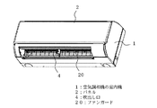
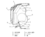
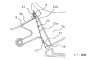
図1は本発明にかかる空気調和機の室内機の斜視図、図2は図1の縦断面図、図3は図2の要部の拡大図、図4、図5はそれぞれ図1に示すファンガード取付構造の要部の斜視図、図6は図1に示すファンガードの斜視図、図7は図1に示すファンガードを風路中央下部において固定する場合のファンガード取付構造の要部の斜視図である。
図において、空気調和機の室内機1はパネル2で覆われ、パネル2の上部には空気の吸込口3が設けられており、パネル2の下部には空気の吹出口4が設けられて、これらの間に吸込口3から吹出口4に到る風路7が形成されている。
空気の吸込口3の下流側には熱交換器5が設けられており、その下流側にはファン6が設けられ、ファン6の下流に位置する吹出し風路7aの下流側には吹出口4を形成するノズル8が設けられている。
Embodiment.
1 is a perspective view of an indoor unit of an air conditioner according to the present invention, FIG. 2 is a longitudinal sectional view of FIG. 1, FIG. 3 is an enlarged view of the main part of FIG. 2, and FIGS. FIG. 6 is a perspective view of the fan guard shown in FIG. 1, and FIG. 7 is a main part of the fan guard installation structure when the fan guard shown in FIG. FIG.
In the figure, an
A
ノズル8の上面壁8aの上流端にはパネル2の幅方向に沿って溝9が形成され、その内部には幅方向に所定の間隔を置いて第1のリブ10が設けられている。また、ノズル8の上部壁8aの幅方向の両端部とその中央部には第1のフック11が設けられており、さらに、ノズル8の両側壁8bにはほぼ三角形状をなす第2のリブ12が設けられている。また、風路中央部のベーンサポート13の下部にはフック15が設けられている。
A
吹出し風路7aの下流端近傍には吹出し風路7aを覆うようにしてファンガード20が取り付けられ、ここから指などを入れてファン6に触れ、怪我をすることがないようにしてある。ファンガード20は横桟20a、この横桟20aと直交して横桟20aを同一ピッチで保持する縦桟20bによって構成されている。ファンガード20の上端部は溝9に挿入できるようになっており、第1のリブ10によってファンガード20が前後に動くのを規制している。
A
ファンガード20の上部端の幅方向の左右端と中央部にはほぼロ状に形成した第1の係止部22が設けられ、この第1の係止部22をノズル8の第1のフック11に係止して、ファンガード20を取付けるようにしてある。また、ファンガード20の下端部の幅方向の左右端には同方向(上流側)に斜めに折り曲げられたロ状の第2の係止部23が設けられ、この第2の係止部23がノズル8に設けた第2のリブ12の隙間に係止することで固定されるようになっている。さらに、ファンガード20の幅方向中央部の上方にはほぼコ字状に開口した開口部24を設けてあり、この開口部24の横桟20aが第2のフック15に係止するようになっている。
なお、ファンガード20と吹出し風路7aの下壁16の間には、所定の幅で隙間17が設けられている。
A
A gap 17 having a predetermined width is provided between the
上記のように構成した空気調和機の室内機1を組立てるには、ファンガード20の上端部をノズル8に設けた溝9に挿入し、ファンガード20の第1の係止部22をノズル8の第1のフック11に係止し、溝9内に設けられた第1のリブ10によってファンガード20の前後の移動を阻止するようにする。
さらに、ファンガード20の下部端に設けられた第2の係止部23を、ノズル8の風路壁8aに設けた第2のリブ12の隙間に係止させて固定する。この第2のリブ12の形状は三角形をしているため、ファンガード20を第2のリブ12の隙間に挿入する際、斜面をすべるようにして動くため、容易に固定することができる。
次に、ファンガード20の開口部24の下側に位置する横桟20aを、第2のフック15に固定する。
To assemble the
Further, the
Next, the
次に、上記のようにして組み立てた空気調和機の室内機1の動作を説明する。空気調和機の室内機1のパネル2の上部から吸い込まれた空気は、風路7に入り、熱交換器5を通過し、ここで熱交換が行われる。熱交換された空気は、その後、ファン6の回転によって、吹出し風路7aを経由して、吹出し口4から外部に送り出される。
Next, operation | movement of the
以上のように、本実施の形態によれば、ファンガード20の上部端がノズル8の溝9に固定され、下部端は幅方向の両端部においてノズル8の両側壁8bに固定されるため、別部材を用いることなくファンガード20を取り付けることができる。また、別部材を使用せずにファンガード20をノズル8の溝9に挿入することができるため、風路7内に風路抵抗となるものがなく、このため吹出し風量を増加することができる。
また、風路中央のベーンサポート13の下部に第2のフック15を設け、ファンガード20の幅方向の中央下部をフック15によって固定するので、風路幅が広い場合にもファンガード20がたわむことがなく、ファンガード20が外れるのを防止することができる。
As described above, according to the present embodiment, the upper end of the
In addition, since the
また、ファンガード20と吹出し風路7aの下壁16の間に所定の幅の隙間17を設けた場合は、吹出し風路7aの下壁16とファンガード20の当たりによるビビリ音の発生を防ぐことができ、さらに、ファンガード20への2次空気の進入による着露を防ぐことができる。
Further, when a gap 17 having a predetermined width is provided between the
1 空気調和機の室内機、2 パネル、4 吹出し口、5 熱交換器、6 ファン、7 風路、7a 吹出し風路、8 ノズル、9 溝、10 第1のリブ、11 第1のフック、12 第2のリブ、13 ベーンサポート、15 第2のフック、17 隙間、20 ファンガード、22 第1の係止部、23 第2の係止部。
DESCRIPTION OF
Claims (5)
前記風路の下流側の上部に設けられ、前記ファンガードの幅方向両端部の上部に形成された第1の係止部を係止する第1のフックと、
前記風路の下流側の下部に設けられ、前記ファンガードの幅方向両端部の下部に形成された第2の係止部を係止する第2のリブと、
前記風路の下流側の上部に前記吹出口の幅方向に沿って設けられ、前記ファンガードの上端部が挿入される嵌合溝と、
を備え、
前記嵌合溝の内部には、
当該嵌合溝の幅方向に所定の間隔を置いて設けられ、前記ファンガードが前後に動くのを阻止する第1のリブを備えた
ことを特徴とするファンガードの取付構造。 A fan guard mounting structure that is located downstream of a fan provided in an air passage from the suction port to the air outlet and is provided so as to cover the air passage,
A first hook that is provided at an upper portion on the downstream side of the air passage and that locks a first locking portion formed at an upper portion of both end portions in the width direction of the fan guard;
A second rib that is provided at a lower portion on the downstream side of the air passage and that locks a second locking portion formed at a lower portion of both end portions in the width direction of the fan guard;
A fitting groove that is provided along the width direction of the outlet in the upper part on the downstream side of the air passage, and into which the upper end of the fan guard is inserted,
Equipped with a,
Inside the fitting groove,
A fan guard mounting structure comprising a first rib provided at a predetermined interval in the width direction of the fitting groove and preventing the fan guard from moving back and forth .
ことを特徴とする請求項1記載のファンガードの取付構造。 A nozzle that forms the air outlet is provided on the downstream side of the air passage, and the fitting groove and the first rib are provided on the upper wall of the nozzle, and the second wall is provided on both side walls of the nozzle. mounting structure of a fan guard according to claim 1, wherein a rib is provided.
ことを特徴とする請求項1又は2に記載のファンガードの取付構造。 The fan guard has a plurality of horizontal rails, and is provided at a lower central portion on the downstream side of the air passage, and includes a second hook for locking the horizontal rails of the fan guard. Or the mounting structure of the fan guard of 2 .
ことを特徴とする請求項1〜3のいずれかに記載のファンガードの取付構造。 Mounting structure of a fan guard according to any one of claims 1 to 3, wherein a gap is provided between the lower portion of the air passage between the fan guard.
この熱交換器の下流側に配置され、前記吸込口から空気を吸い込み、前記熱交換器で熱交換された前記空気を前記吹出口から送り出すファンと、
このファンの下流に位置して前記風路を覆うように設けられたファンカードと、
請求項1〜4のいずれかに記載のファンガードの取付構造と、
を備えたことを特徴とする空気調和機。 A heat exchanger disposed on the downstream side of the suction port of the air passage leading from the suction port to the blower outlet in a panel provided with the suction port at the upper part and the blower outlet at the lower part,
A fan that is arranged on the downstream side of the heat exchanger, sucks air from the suction port, and sends out the air heat-exchanged by the heat exchanger from the air outlet;
A fan card provided downstream of the fan so as to cover the air path;
The mounting structure of the fan guard according to any one of claims 1 to 4 ,
An air conditioner characterized by comprising:
Priority Applications (1)
| Application Number | Priority Date | Filing Date | Title |
|---|---|---|---|
| JP2005313787A JP4698384B2 (en) | 2005-10-28 | 2005-10-28 | Fan guard mounting structure and air conditioner having fan guard mounting structure |
Applications Claiming Priority (1)
| Application Number | Priority Date | Filing Date | Title |
|---|---|---|---|
| JP2005313787A JP4698384B2 (en) | 2005-10-28 | 2005-10-28 | Fan guard mounting structure and air conditioner having fan guard mounting structure |
Publications (3)
| Publication Number | Publication Date |
|---|---|
| JP2007120864A JP2007120864A (en) | 2007-05-17 |
| JP2007120864A5 JP2007120864A5 (en) | 2007-11-29 |
| JP4698384B2 true JP4698384B2 (en) | 2011-06-08 |
Family
ID=38144905
Family Applications (1)
| Application Number | Title | Priority Date | Filing Date |
|---|---|---|---|
| JP2005313787A Active JP4698384B2 (en) | 2005-10-28 | 2005-10-28 | Fan guard mounting structure and air conditioner having fan guard mounting structure |
Country Status (1)
| Country | Link |
|---|---|
| JP (1) | JP4698384B2 (en) |
Cited By (1)
| Publication number | Priority date | Publication date | Assignee | Title |
|---|---|---|---|---|
| JP2015059704A (en) * | 2013-09-19 | 2015-03-30 | 株式会社富士通ゼネラル | Air conditioner |
Families Citing this family (2)
| Publication number | Priority date | Publication date | Assignee | Title |
|---|---|---|---|---|
| JP4698649B2 (en) * | 2007-08-30 | 2011-06-08 | 三菱電機株式会社 | Air conditioner |
| JP4717050B2 (en) * | 2007-11-27 | 2011-07-06 | 三菱電機株式会社 | Air conditioner |
Citations (7)
| Publication number | Priority date | Publication date | Assignee | Title |
|---|---|---|---|---|
| JPS63198952U (en) * | 1987-06-10 | 1988-12-21 | ||
| JPH06213470A (en) * | 1993-01-12 | 1994-08-02 | Matsushita Electric Ind Co Ltd | Fan guard device of air conditioner |
| JPH08226698A (en) * | 1995-02-23 | 1996-09-03 | Matsushita Electric Ind Co Ltd | Air conditioner |
| JPH10132318A (en) * | 1996-10-25 | 1998-05-22 | Mitsubishi Electric Corp | Fan guard mounting structure for air conditioner |
| JPH1183070A (en) * | 1997-09-01 | 1999-03-26 | Daikin Ind Ltd | Fan guard device |
| JP2004020065A (en) * | 2002-06-18 | 2004-01-22 | Fujitsu General Ltd | Air conditioner |
| JP2005188871A (en) * | 2003-12-26 | 2005-07-14 | Mitsubishi Electric Corp | Air conditioner and die structure of lateral diffuser base mounted on it |
-
2005
- 2005-10-28 JP JP2005313787A patent/JP4698384B2/en active Active
Patent Citations (7)
| Publication number | Priority date | Publication date | Assignee | Title |
|---|---|---|---|---|
| JPS63198952U (en) * | 1987-06-10 | 1988-12-21 | ||
| JPH06213470A (en) * | 1993-01-12 | 1994-08-02 | Matsushita Electric Ind Co Ltd | Fan guard device of air conditioner |
| JPH08226698A (en) * | 1995-02-23 | 1996-09-03 | Matsushita Electric Ind Co Ltd | Air conditioner |
| JPH10132318A (en) * | 1996-10-25 | 1998-05-22 | Mitsubishi Electric Corp | Fan guard mounting structure for air conditioner |
| JPH1183070A (en) * | 1997-09-01 | 1999-03-26 | Daikin Ind Ltd | Fan guard device |
| JP2004020065A (en) * | 2002-06-18 | 2004-01-22 | Fujitsu General Ltd | Air conditioner |
| JP2005188871A (en) * | 2003-12-26 | 2005-07-14 | Mitsubishi Electric Corp | Air conditioner and die structure of lateral diffuser base mounted on it |
Cited By (1)
| Publication number | Priority date | Publication date | Assignee | Title |
|---|---|---|---|---|
| JP2015059704A (en) * | 2013-09-19 | 2015-03-30 | 株式会社富士通ゼネラル | Air conditioner |
Also Published As
| Publication number | Publication date |
|---|---|
| JP2007120864A (en) | 2007-05-17 |
Similar Documents
| Publication | Publication Date | Title |
|---|---|---|
| KR101702169B1 (en) | Indoor unit for cassette type air conditoiner | |
| EP1890087A1 (en) | Air conditioner with air flow guide element for noise reduction | |
| EP1884718A2 (en) | Air Conditioner | |
| US20090130970A1 (en) | Exhaust fan and method of operating the same | |
| JP5402616B2 (en) | Air conditioner | |
| KR20150041340A (en) | Indoor unit for cassette type air conditoiner | |
| KR101833303B1 (en) | Indoor unit for cassette type air conditoiner | |
| JP4698384B2 (en) | Fan guard mounting structure and air conditioner having fan guard mounting structure | |
| JP5174949B2 (en) | Simultaneous exhaust / exhaust fan | |
| WO2010050349A1 (en) | Air conditioner | |
| WO2017033241A1 (en) | Indoor unit of air conditioner | |
| JP5691787B2 (en) | Air conditioner | |
| JP5786740B2 (en) | Indoor unit | |
| KR102521424B1 (en) | Ceiling type air conditioner | |
| JP2007120864A5 (en) | ||
| JP3608385B2 (en) | Air conditioner | |
| JP6403012B2 (en) | Embedded ceiling air conditioner | |
| KR100925718B1 (en) | Indoor unit for air conditioner | |
| KR20090044504A (en) | Base-assembly for out door unit of an air conditioner | |
| KR100751121B1 (en) | Indoor unit for air-conditioner | |
| CN221375802U (en) | Air outlet frame assembly and air conditioner | |
| JP7494038B2 (en) | Air Curtain Device | |
| KR20240125229A (en) | Air conditioner | |
| JP2004338595A (en) | Air conditioning unit | |
| JPH06213470A (en) | Fan guard device of air conditioner |
Legal Events
| Date | Code | Title | Description |
|---|---|---|---|
| A521 | Written amendment |
Free format text: JAPANESE INTERMEDIATE CODE: A523 Effective date: 20071015 |
|
| A621 | Written request for application examination |
Free format text: JAPANESE INTERMEDIATE CODE: A621 Effective date: 20071015 |
|
| A131 | Notification of reasons for refusal |
Free format text: JAPANESE INTERMEDIATE CODE: A131 Effective date: 20100907 |
|
| A521 | Written amendment |
Free format text: JAPANESE INTERMEDIATE CODE: A523 Effective date: 20101028 |
|
| TRDD | Decision of grant or rejection written | ||
| A01 | Written decision to grant a patent or to grant a registration (utility model) |
Free format text: JAPANESE INTERMEDIATE CODE: A01 Effective date: 20110222 |
|
| A61 | First payment of annual fees (during grant procedure) |
Free format text: JAPANESE INTERMEDIATE CODE: A61 Effective date: 20110301 |
|
| R150 | Certificate of patent or registration of utility model |
Ref document number: 4698384 Country of ref document: JP Free format text: JAPANESE INTERMEDIATE CODE: R150 |
|
| R250 | Receipt of annual fees |
Free format text: JAPANESE INTERMEDIATE CODE: R250 |
|
| R250 | Receipt of annual fees |
Free format text: JAPANESE INTERMEDIATE CODE: R250 |
|
| R250 | Receipt of annual fees |
Free format text: JAPANESE INTERMEDIATE CODE: R250 |
|
| R250 | Receipt of annual fees |
Free format text: JAPANESE INTERMEDIATE CODE: R250 |
|
| R250 | Receipt of annual fees |
Free format text: JAPANESE INTERMEDIATE CODE: R250 |
|
| R250 | Receipt of annual fees |
Free format text: JAPANESE INTERMEDIATE CODE: R250 |
|
| R250 | Receipt of annual fees |
Free format text: JAPANESE INTERMEDIATE CODE: R250 |
|
| R250 | Receipt of annual fees |
Free format text: JAPANESE INTERMEDIATE CODE: R250 |


