JP4697148B2 - Electric compressor - Google Patents
Electric compressor Download PDFInfo
- Publication number
- JP4697148B2 JP4697148B2 JP2007014772A JP2007014772A JP4697148B2 JP 4697148 B2 JP4697148 B2 JP 4697148B2 JP 2007014772 A JP2007014772 A JP 2007014772A JP 2007014772 A JP2007014772 A JP 2007014772A JP 4697148 B2 JP4697148 B2 JP 4697148B2
- Authority
- JP
- Japan
- Prior art keywords
- heat
- inverter
- thermo module
- electric compressor
- control device
- Prior art date
- Legal status (The legal status is an assumption and is not a legal conclusion. Google has not performed a legal analysis and makes no representation as to the accuracy of the status listed.)
- Expired - Fee Related
Links
Images


Landscapes
- Applications Or Details Of Rotary Compressors (AREA)
- Compressor (AREA)
- Rotary Pumps (AREA)
Description
本発明は、圧縮機構部と、この圧縮機構部を駆動する電動機を機体容器に内蔵し、さらに、前記電動機の駆動(回転)を制御するインバータ制御装置を前記機体容器に設けた電動圧縮機に関するものである。 The present invention relates to an electric compressor in which a compression mechanism unit and an electric motor that drives the compression mechanism unit are incorporated in a body container, and an inverter control device that controls driving (rotation) of the motor is provided in the body container. Is.
この種の電動圧縮機として、圧縮機構部および電動機を具備する圧縮機部と、前記電動機の駆動を制御するインバータ装置の収納部を気密状態に仕切り、一つの機体容器として一体化した構成が知られている(例えば、特許文献1参照)。 As this type of electric compressor, there is known a structure in which a compressor unit including a compression mechanism unit and an electric motor and a storage unit of an inverter device for controlling the driving of the electric motor are partitioned in an airtight state and integrated as a single body container. (For example, refer to Patent Document 1).
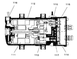
図5は、上記特許文献1に示される電動圧縮機の縦断面図であり、電動機111を収容した機体容器112内に圧縮機構部113を組込み、さらに圧縮機構部113を挟む如く電動機111と反対側に位置してインバータ制御装置114を収容したインバータケース115が、機体容器112と気密状態に仕切られて設けられた構成となっている。そして、機体容器112とインバータケース115は、同軸上に配置され、ボルト等で締結されている。また、インバータ制御装置114は、その発熱部が圧縮機構部113に面して配置されている。
FIG. 5 is a longitudinal cross-sectional view of the electric compressor shown in
したがって、圧縮機構部113に設けられた吸入口116より流入された吸入冷媒は、一旦インバータケース115と圧縮機構部113の間に形成された通路117に導かれ、インバータ装置114の発熱部と熱交換を図った後、圧縮機構部113に吸入される。さらに圧縮機構部113で圧縮された冷媒ガスは電動機111を冷却した後、機体容器112に設けられた吐出口118より吐出される。
しかし、上記特許文献1に記載の構造は、吸入冷媒によってのみインバータ制御装置114の高発熱部品を冷却する構造であるため、圧縮機の低速運転時、即ち冷媒循環量が少ない場合では十分な熱交換が行えなくなり、インバータ制御装置114の発熱部品が冷却不足となって性能、信頼性に大きな影響を及ぼす可能性がある。
However, since the structure described in
また、圧縮機が自動車用のエアコンとして用いられ、エンジンに直接装着される場合には、エンジンからの熱伝導あるいは輻射伝熱による加熱等によって圧縮機内部の温度が上昇し、圧縮機が停止中の場合でもインバータ部品が加熱され、部品劣化を加速する原因となるものであった。 In addition, when the compressor is used as an air conditioner for an automobile and is directly mounted on the engine, the internal temperature of the compressor rises due to heat conduction or radiant heat from the engine, and the compressor is stopped. Even in this case, the inverter component was heated, which accelerated the deterioration of the component.
本発明は上記従来の課題に着目し、主として、機体容器を大型化することなくインバータ制御装置の冷却が効率的に図れる電動圧縮機を提供することを目的とする。 The present invention pays attention to the above-described conventional problems, and mainly aims to provide an electric compressor capable of efficiently cooling the inverter control device without increasing the size of the fuselage container.
上記従来の課題を解決するために本発明は、インバータ制御装置を、吸入冷媒が低温である特性を利用して冷却することに加え、サーモモジュール(ペルチェ素子あるいはペルチェモジュールとも称される)の冷却作用(熱移動作用)を利用して冷却するようにしたものである。 In order to solve the above-described conventional problems, the present invention cools an inverter control device by utilizing a characteristic that the refrigerant sucked at a low temperature, and also cools a thermo module (also referred to as a Peltier element or a Peltier module). Cooling is performed using the action (heat transfer action).
さらに詳述すると、冷媒の吸入、圧縮および吐出を行う圧縮機構部と、該圧縮機構部を駆動する電動機とを内蔵した機体容器に電動機を駆動制御するインバータ制御装置内蔵のインバータケースを組込んだ電動圧縮機において、インバータ制御装置の発熱部(発熱部品)を冷却する冷却手段として、吸入冷媒温度を発熱部に伝達する熱伝達手段と、発熱部の冷却を行うサーモモジュールをインバータケース内に配置したものである。これによって、電動圧縮機の運転状況に応じて、インバータ制御装置における発熱部を、吸入冷媒による冷却と、サーモモジュールによる冷却作用を利用した冷却の組合せにて冷却することができる。 More specifically, an inverter case with a built-in inverter control device that controls the drive of an electric motor is incorporated in a fuselage container that incorporates a compression mechanism that sucks, compresses and discharges refrigerant and an electric motor that drives the compression mechanism. In the electric compressor, as the cooling means for cooling the heat generating part (heat generating part) of the inverter control device, a heat transfer means for transmitting the intake refrigerant temperature to the heat generating part and a thermo module for cooling the heat generating part are arranged in the inverter case. It is a thing. Thereby, according to the driving | running state of an electric compressor, the heat-emitting part in an inverter control apparatus can be cooled by the combination of cooling by a suction | inhalation refrigerant | coolant, and cooling using the cooling effect | action by a thermomodule.
本発明の電動圧縮機は、電動機の回転、駆動を制御するインバータ制御装置における発熱部を、吸入冷媒の低温である特性と、サーモモジュールの冷却作用(熱移動作用)を利用して冷却することができ、圧縮機の低回転時、あるいは空調負荷等の冷凍サイクル負荷が高い場合におけるインバータ制御装置の冷却効率を高めることが可能となり、インバータ部品の熱による劣化を抑制することができる。 The electric compressor of the present invention cools the heat generating part in the inverter control device that controls the rotation and driving of the electric motor by utilizing the low temperature characteristic of the suction refrigerant and the cooling action (heat transfer action) of the thermo module. It is possible to increase the cooling efficiency of the inverter control device when the compressor is rotating at a low speed or when the refrigeration cycle load such as an air conditioning load is high, and the deterioration of the inverter components due to heat can be suppressed.
また、ハイブリッド車等のエンジンに直接装着される電動圧縮機においては、エンジンからの加熱、振動等の過酷な環境下においても電動圧縮機としての性能および信頼性を損なわず、電動圧縮機を運転することが可能となる。 In the case of an electric compressor that is directly mounted on an engine such as a hybrid vehicle, the electric compressor is operated without impairing the performance and reliability of the electric compressor even under severe environments such as heating and vibration from the engine. It becomes possible to do.
請求項1に記載の発明は、冷媒の吸入、圧縮および吐出を行う圧縮機構部と、該圧縮機構部を駆動する電動機を内蔵した機体容器と、前記電動機を駆動するインバータ制御装置を内蔵したインバータケースと、前記インバータケースを閉塞するケースカバーを具備し、さらに前記インバータ制御装置の発熱部を吸入冷媒によって冷却するようにした電動圧縮機において、放熱面と吸熱面を具備するサーモモジュールを備え、前記吸熱面を前記インバータ制御装置の発熱部と熱伝導可能に設け、前記インバータケースにより前記圧縮機構部に吸入される冷媒の吸入冷媒通路を形成し、前記サーモモジュールを前記吸入冷媒通路の近傍に配置し、前記サーモモジュールの放熱面を前記吸入冷媒通路壁面と熱交換可能に設け、さらに前記インバータ制御装置の発熱部を前記吸入冷媒通路壁面と熱伝導可能に設けて、前記インバータ制御装置が前記サーモモジュールにより補助的に冷却されるものである。 According to the first aspect of the present invention, there is provided a compression mechanism portion for sucking, compressing and discharging refrigerant, a body container incorporating a motor for driving the compression mechanism portion, and an inverter having a built-in inverter control device for driving the motor. An electric compressor including a case and a case cover that closes the inverter case, and further configured to cool a heat generating portion of the inverter control device with a sucked refrigerant, and includes a thermo module having a heat radiating surface and a heat absorbing surface; The heat absorption surface is provided so as to be able to conduct heat with the heat generating portion of the inverter control device, the refrigerant case sucked into the compression mechanism portion is formed by the inverter case, and the thermo module is placed in the vicinity of the suction refrigerant passage. And the heat dissipating surface of the thermo module is provided so as to be able to exchange heat with the suction refrigerant passage wall surface, and the inverter Provided the heat generating portion of the control device to be the suction refrigerant passage wall surface and the heat conduction, in which the inverter control device is assisted cooled by the thermo-module.
かかる構成とすることにより、前記インバータ制御装置における発熱部の冷却を、圧縮機構部の吸入冷媒(戻り冷媒)の冷熱を利用しての冷却に加えて、前記サーモモジュールの吸熱作用にて行えるため、前記発熱部の冷却効果を高めることが可能となり、インバータ部品の劣化加速が抑制できる。また、前記インバータケースは、ケースカバーによって閉塞されているため、故障の要因となる雨水、塵埃等の侵入が抑制でき、信頼性を高めることができるものである。また、サーモモジュールの吸熱作用を高温熱部と、また放熱作用を低温熱部とそれぞれ行うことになり、その結果、サーモモジュールの吸熱作用と放熱作用の均衡が図れ、サーモモジュールの動作効率を高めることができる。また、前記イン
バータ制御装置の発熱部は前記吸入冷媒通路壁面を介して吸入冷媒と熱交換するため、インバータ部品の熱による劣化加速が抑制できるものである。
With this configuration, the heat generation unit in the inverter control device can be cooled by the heat absorption action of the thermo module in addition to the cooling using the cold heat of the suction refrigerant (return refrigerant) of the compression mechanism unit. The cooling effect of the heat generating portion can be enhanced, and the acceleration of deterioration of the inverter components can be suppressed. Further, since the inverter case is closed by the case cover, it is possible to suppress the intrusion of rainwater, dust, and the like that cause failure, and to improve the reliability. In addition, the heat absorption action of the thermo module is performed with the high temperature heat section and the heat radiation action is performed with the low temperature heat section. As a result, the heat absorption action and the heat radiation action of the thermo module are balanced, and the operation efficiency of the thermo module is increased. be able to. In addition, the in
Since the heat generating part of the barter control device exchanges heat with the sucked refrigerant through the suction refrigerant passage wall surface, it is possible to suppress deterioration of the inverter parts due to heat.
請求項2に記載の発明は、請求項1記載の発明において、低回転領域において冷媒循環量が減少した場合に補助的に冷却されるようにしたものである。
The invention according to
かかる構成とすることにより、ヒートシンク部での冷却作用のみでは効果が期待できなくなり、インバータが想定以上に高温となった場合でも、サーモモジュールを通電制御することにより、その吸熱面でインバータにおける発熱部の発熱を吸収”し、発熱面で端部壁における凹部の底壁を介して戻り冷媒と熱交換を行うことにより、インバータの異常な温度上昇を抑止することが可能となるものである。 By adopting such a configuration, it is impossible to expect an effect only by the cooling action at the heat sink part, and even when the inverter becomes hotter than expected, by controlling the energization of the thermo module, the heat generating part in the inverter on the heat absorption surface In this case, the heat generation surface absorbs the heat and exchanges heat with the return refrigerant through the bottom wall of the recess in the end wall on the heat generation surface, thereby suppressing an abnormal temperature rise of the inverter.
請求項3に記載の発明は、前記吸入冷媒通路壁面にサーモモジュールを収納する凹部を設け、凹部の底面にサーモモジュールの放熱面を密着させたものであり、サーモモジュールの取付け時の位置決めが可能となり、また凹部形成によって吸入冷媒通路の壁厚が薄くなるため、その分サーモモジュールにおける放熱面と吸入冷媒との熱交換効率が向上する。 According to a third aspect of the present invention, a recess for housing the thermo module is provided on the wall surface of the suction refrigerant passage, and the heat radiation surface of the thermo module is in close contact with the bottom surface of the recess, and positioning when the thermo module is mounted is possible. Further, since the wall thickness of the suction refrigerant passage is reduced by forming the recess, the heat exchange efficiency between the heat radiation surface and the suction refrigerant in the thermo module is improved accordingly.
請求項4に記載の発明は、前記サーモモジュールと凹部の周壁との間に断熱層を設けたものであり、前記断熱層によってサーモモジュールにおける放熱面側から吸熱面側への熱のリークを抑制することができ、その結果、サーモモジュールにおける吸熱面、放熱面からの吸熱作用、放熱作用が正規の状態もしくはそれに近い状態で行え、冷却効率の維持が図れるものである。 According to a fourth aspect of the present invention, a heat insulating layer is provided between the thermo module and the peripheral wall of the recess, and the heat insulating layer suppresses heat leakage from the heat radiation surface side to the heat absorption surface side in the thermo module. As a result, the endothermic surface, the endothermic action from the radiating surface, and the endothermic action of the thermomodule can be performed in a normal state or a state close thereto, and the cooling efficiency can be maintained.
請求項5に記載の発明は、前記サーモモジュールの制御部をインバータケース内に配置したものであり、インバータ制御装置とサーモモジュールの回路系統の組込みが一括して行え、組立て作業性の向上が可能となる。
The invention according to
請求項6に記載の発明は、インバータ制御装置の発熱部とサーモモジュールの吸熱面を当接し、さらに前記サーモモジュールの放熱面と吸入冷媒通路壁面を当接した構成において、前記インバータ制御装置とサーモモジュールの離反および前記サーモモジュールの前記吸入通路壁面からの離反を規制する離反規制手段を設けたものである。 According to a sixth aspect of the present invention, there is provided a configuration in which the heat generating portion of the inverter control device and the heat absorption surface of the thermo module are in contact with each other, and the heat dissipation surface of the thermo module and the suction refrigerant passage wall surface are in contact with each other. Separation regulating means for regulating separation of the module and separation of the thermo module from the suction passage wall surface is provided.
かかる構成によれば、熱膨張・収縮等に起因して微妙にインバータケースに歪が生じても、離反規制手段によってインバータ制御装置とサーモモジュールと吸入冷媒通路のそれぞれの当接を維持することが可能となり、その結果、サーモモジュールの吸熱作用および放熱作用がインバータ制御装置および吸入通路壁面との間において安定して行え、インバータ制御装置の発熱部における冷却作用の信頼性を向上させることができる。 According to such a configuration, even if the inverter case is slightly distorted due to thermal expansion / contraction, etc., the contact between the inverter control device, the thermo module, and the suction refrigerant passage can be maintained by the separation regulating means. As a result, the heat absorbing action and heat releasing action of the thermo module can be stably performed between the inverter controller and the suction passage wall surface, and the reliability of the cooling action in the heat generating portion of the inverter controller can be improved.
請求項7に記載の発明は、インバータ制御装置を構成する基板を、インバータケースに固定することにより、前記インバータ制御装置とサーモモジュールの離反および前記サーモモジュールの前記吸入通路壁面からの離反を規制するようにしたものであり、インバータ制御装置のインバータケースへの固定と、インバータ装置と吸入冷媒通路壁によるサーモモジュールの挟持固定および前述の離反規制が同時に行え、組立て作業性の向上が可能となる。 The invention according to claim 7 regulates separation of the inverter control device and the thermo module and separation of the thermo module from the suction passage wall surface by fixing a substrate constituting the inverter control device to the inverter case. Thus, the inverter control device can be fixed to the inverter case, the thermo module can be held and fixed by the inverter device and the suction refrigerant passage wall, and the above-described separation control can be performed at the same time, and the assembly workability can be improved.
請求項8に記載の発明は、離反規制手段を、ケースカバーに設けられた押圧部材で形成し、この押圧部材により少なくともインバータ制御装置を構成する基板を介してサーモモジュールを吸入冷媒通路壁面へ押圧するようにしたものであり、押圧部材の押圧力にてインバータ制御装置とサーモモジュールと吸入冷媒通路のそれぞれの離反を規制しているため、熱膨張・収縮等に起因したインバータケースの微妙な歪に追従して前記インバータ制御装置とサーモモジュールと吸入冷媒通路のそれぞれの当接が維持でき、その結果、サーモモジュールによるインバータ制御装置の発熱部における冷却作用の信頼性を向上させることができる。 According to an eighth aspect of the present invention, the separation regulating means is formed by a pressing member provided on the case cover, and the thermo module is pressed against the suction refrigerant passage wall surface by at least the substrate constituting the inverter control device by the pressing member. Because the separation of the inverter control device, thermo module, and suction refrigerant passage is regulated by the pressing force of the pressing member, subtle distortion of the inverter case due to thermal expansion / contraction, etc. Accordingly, the contact between the inverter control device, the thermo module, and the suction refrigerant passage can be maintained. As a result, the reliability of the cooling action in the heat generating portion of the inverter control device by the thermo module can be improved.
請求項9に記載の発明は、前記押圧部材を、バネ部材としたものであり、バネ係数の選択により最適な押圧力が得られ、インバータ制御装置の基板の損傷等が防止できる。 According to the ninth aspect of the present invention, the pressing member is a spring member, and an optimum pressing force can be obtained by selecting a spring coefficient, and damage to the substrate of the inverter control device can be prevented.
請求項10に記載の発明は、ケースカバーの外殻を覆う断熱カバーを設けたもので、かかることにより、外部の熱のインバータケース内への侵入が抑制できるため、インバータ制御装置およびサーモモジュールは外部の熱の影響を直接受けることが抑制され、その結果、インバータ制御装置における温度上昇の助成要因の一つを排除し、前記サーモモジュールの熱負荷の増大およびこれに起因する入力の増加を抑制することができ、総合的な消費電力の増加抑制を図ることができる。
The invention according to
請求項11に記載の発明は、機体容器とインバータケースの接合部に断熱手段を設けたもので、かかることにより、機体容器からインバータケースへの熱の侵入を抑制することができ、インバータ制御装置における温度上昇の助成要因の一つを排除し、サーモモジュールの消費電力の増加を抑制することができる。 According to the eleventh aspect of the present invention, a heat insulating means is provided at the joint portion between the fuselage container and the inverter case, and as a result, the intrusion of heat from the fuselage container to the inverter case can be suppressed. This can eliminate one of the subsidizing factors for the temperature rise and suppress the increase in power consumption of the thermo module.
請求項12に記載の発明は、ケースカバー内の熱を外部へ排出する換気手段を設けたもので、かかることにより、ケースカバーとインバータケースで形成される空間内の熱のこもりが抑制でき、インバータ制御装置における温度上昇の助成要因の一つを排除してインバータ装置の冷却が効率よく行えるものである。
The invention according to
以下、本発明の実施の形態について、図面を参照しながら説明する。なお、この実施の形態によって本発明が限定されるものではない。 Hereinafter, embodiments of the present invention will be described with reference to the drawings. Note that the present invention is not limited to the embodiments.
(実施の形態1)
図1は、本発明の実施の形態1における電動圧縮機の縦断面図である。図1においては、電動圧縮機1の胴部の周りにある取付け脚2によって横向きに設置される横型の電動圧縮機の場合を一つの例として示している。図2は、同電動圧縮機1における要部の斜視断面図で、インバータ制御装置7とサーモモジュール50の取付け部の断面を示す。
(Embodiment 1)
FIG. 1 is a longitudinal sectional view of the electric compressor according to
電動圧縮機1は、端部壁3aを底壁とする有底円筒状に形成されたアルミダイキャスト等の金属製のケーシング本体3と、そのケーシング本体3内に組込まれた固定子4aと回転子4bを具備する電動機(DCブラシレスモータ)4と、ケーシング本体3内に嵌入または圧入された圧縮機構部5を主要構成とし、電動機4の回転軸は、圧縮機構部5の駆動軸13を構成している。
The
そして、ケーシング本体3における圧縮機構部5側の開口端部は、一端(一面)が開口したアルミダイキャスト等の金属製のインバータケース6によって閉塞され、ケーシング本体3内を密封状態としている。前記インバータケース6とケーシング本体3は、本発明の機体容器を構成するものである。
And the opening edge part by the side of the
電動機4は、インバータケース6内に組込まれたインバータ制御装置(以下、インバータと称す)7によって駆動およびその回転数が制御される。また、ケーシング本体3内には、圧縮機構部5を含む各摺動部の潤滑に供する液を貯留する貯液部8を備えている。この電動圧縮機1において、取り扱う冷媒はガス冷媒であり、圧縮機構部5における各摺動部の潤滑やシールに供する液としては潤滑油9を採用している。
The
本実施の形態1における電動圧縮機1の圧縮機構部5は、スクロール方式のものである。このスクロール方式の構成(スクロール機構)は、周知の如く、固定鏡板11aおよび旋回鏡板12aを具備し、各鏡板部11a、12aからそれぞれ羽根が立ち上がった構成の固定スクロール11と旋回スクロール12とを噛合わせて圧縮空間10を形成するもので、電動機4を駆動することにより、駆動軸13を介して旋回スクロール12を固定スクロール11に対して円軌道運動させ、これによって圧縮空間10に移動が伴う容積変化を生じさせる。
The
圧縮空間10の容積変化により、外部サイクル(図示せず)から帰還する吸入冷媒14を、インバータケース6に設けた吸入口15より圧縮機構部5の吸入側へ吸入し、前述の如く圧縮空間10で圧縮した後、圧縮空間10の略中央に位置する吐出孔29よりケーシング本体3内へ吐出し、ケーシング本体3に設けた吐出口16より外部サイクルへ吐出する。外部サイクルは、一例として周知の冷凍サイクルが該当し、本発明の要旨と直接関係しないため、図示を省略する。
Due to the volume change of the
また、ケーシング本体3内には、軸線方向の一方の端部壁3a側からポンプ17と、駆動軸13の一方を支持する副軸受18と、駆動軸13の他方を支持する主軸受19と、主軸受19を固定した主軸受部材20が配置されている。
Further, in the
ポンプ17は駆動軸13の回転に伴って回転駆動されるもので、端部壁3aの外面から収容し、その後にOリング等のシール部材21aを介して嵌め付けたポンプカバー21にて保持される。その結果、ポンプカバー21の内側に吸上げ通路23を介して貯液部8に通じるポンプ室22が形成されている。副軸受18は端部壁3aに形成した支持部18aに支持固定されおり、駆動軸13のポンプ17に連結している側を軸支する。
The
電動機4の固定子4aは、金属製のあるいは適度な硬度である樹脂製の環状部材24を介してケーシング本体3の内壁に嵌合固定され、駆動軸13に嵌合等の適宜手段にて固定した回転子4bとによって駆動軸13を回転駆動できるようにしている。なお、固定子4aはケーシング本体3の内壁面に直接焼き嵌め固定してもよい。駆動軸13の内部(中心軸部)には給油通路25が形成されている。この給油通路25は、ポンプ17にて貯液部8より汲み上げた潤滑油9を圧縮機構部5の各摺動箇所へ供給する通路を構成している。
The
主軸受部材20は、固定スクロール11と旋回スクロール12を噛合せた状態でボルト締め等の適宜手段(図示せず)によって固定スクロール11に固定されている。そして、主軸受部材20の周縁をケーシング本体3の内壁に形成した段部3bに当たるように位置させ、固定スクロール11をケーシング本体3内に嵌入または圧入することにより圧縮機構5の固定が行われるものである。
The
一方、ケーシング本体3の開口側にOリング等のシール部材11cを介して密封性よく嵌合されたインバータケース6は、ボルト締め等の適宜手段(図示せず)にてケーシング本体3に固定され、また前記インバータケース6の内面側に設けられた隔壁6cが固定スクロール11と当接している。したがって、固定スクロール11および主軸受部材20は、ケーシング本体3の段部3bとインバータケース6によって挟持された状態で固定されている。また、駆動軸13の圧縮機構部5側は主軸受19により軸支されている。
On the other hand, the
さらに、スクロール機構は、主軸受部材20と旋回スクロール12の間にオルダムリング26等の自転拘束部が設けられており、旋回スクロール12の自転を防止して円運動させる構成となっている。そして、駆動軸13を、偏心軸受27を介して旋回スクロール12に連結することにより、駆動軸13の回転によって旋回スクロール12を円軌道上で旋回させる構成となっている。
Further, the scroll mechanism is provided with a rotation restraining portion such as an
また、インバータケース6においては、その内面に設けた隔壁6cとその先端に設けたOリング等のシール部材11bにより、固定スクロール11の固定鏡板11aと気密的に組合せ、この組合せにより端部壁6a(本発明の吸入冷媒通路壁面に相当)とともに吸入口15から圧縮機構部5の吸入側に通じる密閉空間を構成して吸入冷媒通路28を形成している。吸入冷媒通路28の空間の一部には、固定スクロール11に設けられた吐出室壁30aと、この吐出室壁30aにボルト等の適宜手段によって固定された吐出室カバー37によって吐出室30が形成され、固定スクロール11の吐出孔29が吐出室30内に開口している。そして、吐出室30内には、吐出孔29に設けられた所定圧力で開くリード弁29aと、このリード弁29aの開き度合いを規制するリード弁押え29bが設けられている。吐出室30は、固定スクロール11および主軸受部材20におけるそれぞれの外周の一部に設けられた溝部31aとケーシング本体3の内周面で形成される連絡通路31を通じて電動機4側に連通している。
Further, in the
インバータ7は、インバータケース6の端部壁6aを挟んで吸入冷媒通路28の反対面に配置され、回路基板32と電解コンデンサ(図示せず)等を備えて構成されている。インバータケース6の端部壁6aには、インバータ7の発熱部33が当接するヒートシンク部6bと、薄肉部として形成した凹部52が設けられている。ここで、ヒートシンク部6bは端部壁6aの肉厚で形成されており、インバータ7における発熱部33との密着位置を定義するために称しているもので、特に熱容量を多くするために肉厚を厚くする等の加工は施していない。
The
そして、図2に示す如く回路基板32には、発熱度の高いスイッチング素子を含むIPM(インテリジェントパワーモジュール)32aおよびマイクロコンピュータを主体とする制御回路部32b等が配置され、このIPM32aの発熱部33が端部壁6aのヒートシンク部6bで熱的に密着している。
As shown in FIG. 2, the
また、回路基板32は、インバータケース6の適宜箇所に形成したボス部6eにボルト39によって固定されている。さらにサーモモジュール50の通電を制御する回路32dを具備したモジュール制御基板32cも並設されており、このモジュール制御基板32cも、前記回路基板32と同様にインバータケース6の適宜箇所に形成したボス部6eにボルト締めされている。
The
さらに、インバータケース6の凹部52には、サーモモジュール50が前記凹部52の側壁と断熱層51を形成する如く、所定の間隔を形成して配置されている。サーモモジュール50は、周知の如くペルチェ素子あるいはペルチェモジュールとも称され、熱伝導性を有する電気絶縁体の基板上に複数の熱電素子を電流が直列に流れるように配置したもので、通電によるペルチェ効果により一方の面で発熱し、他方の面で吸熱を行うものである。
Furthermore, in the
サーモモジュール50は、その吸熱面がインバータ7の発熱部33と密着し、放熱面が端部壁6a(凹部52の底面)と密着するように設けられており、さらに詳述すると発熱部33と吸熱面、端部壁6a面と発熱面は、それぞれ熱良導性の熱伝導グリース等を介して密着している。そして、サーモモジュール50と発熱部33、端部壁6aとの密着は、図2に示す如く、インバータケース6の適宜箇所に設けたボス部6eにインバータ7の回路基板32をボルト39にて締付け固定することにより保持されている。特に、回路基板32は、ボス部6eの高さ設定あるいはボルト39の締付け度合いにより微妙に撓んだ状態にあり、その撓みの反発力でサーモモジュール50を端部壁6aに押付けている。
The
また、断熱層51は、ヒートシンク部6bからの直接の熱伝達(熱伝導)を阻止し、その熱のサーモモジュール50への影響を抑制することに加え、サーモモジュール50における放熱面側から吸熱面側への熱のリーク(熱伝導経路の短絡)を抑制するためのものである。したがって、サーモモジュール50は、前述の熱のリークが抑制されているため、その吸熱面からの吸熱作用と、放熱面からの放熱作用が定格の状態もしくはそれに近い状態で行え、冷却効率の低下が抑制された構成で取付けられている。この断熱層51は空気層でも良いが、耐熱性の断熱材を設けることにより一層高い断熱効果が期待でき、さらに冷却効率の低下抑制が期待できる。
Further, the
さらに、インバータケース6には隔壁6cを挟み吸入冷媒通路28と並んで位置する接続室6dが設けられており、この接続室6dには、電動機4に接続された雄型ハーネス部(圧縮機ターミナル)34と、インバータ7に接続された雌型ハーネス部35が設けられている。雄型ハーネス部34と雌型ハーネス部35の取付け位置は前述に限るものではないが、インバータ7と電動機4を電気的に接続するものである。
Further, the
インバータ7による電動機4の駆動制御は、空調室温度、冷媒温度等の負荷を検出手段(図示せず)にてモニタし、その結果に基づく負荷信号、制御信号によって、所定の周波数で電動機4の回転を制御するものである。具体的な電動機4の制御内容は、本発明の要旨と直接関係しないため、ここでの説明は省略する。
The drive control of the
また、インバータケース6の開口面は、アルミダイキャスト等の金属製のケースカバー36によって閉塞され、防水、防塵構造が施されている。このケースカバー36は、ボルト36aによってインバータケース6あるいはケーシング本体3に取付けられている。またケースカバー36には、内部の熱(空気)のこもりを防止するための流入口36bと流出口36cが設けられている。したがって、ケースカバー36内部の熱は、所定の条件(外部とケースカバー36内部の温度差あるいは風等による外部とケースカバー36内部の圧力差等)によって点線矢印で示す如く流入口36bから流入し、流出口36cから流出する気流によって排出される。この流れは、条件によっては逆の流れとなる場合もある。また、必要に応じてこの流入口36bと流出口36cに、空気の透過を許容し、水分の透過を拒否する周知の膜体を設けてもよい。
Further, the opening surface of the
次に、上記構成からなる電動圧縮機1の動作について説明する。
Next, the operation of the
インバータ7の起動制御によって電動機4が回転すると、これに伴って駆動軸13が回転し、駆動軸13を介して圧縮機構部5の旋回スクロール12が円軌道運動するとともに、ポンプ17を駆動する。ポンプ17により貯液部8の潤滑油9が駆動軸13の給油通路25を通じて圧縮機構部5に供給され、旋回スクロール12は供給された潤滑油9によって潤滑およびシール作用を受けながら回転し、インバータケース6に設けた吸入口15を通じて冷凍サイクルから帰還した冷媒14を吸入する。吸入された低温の冷媒14は、吸入冷媒通路28の空間において端部壁6aを冷却し、固定鏡板11aの通路穴(図示せず)を介して圧縮空間10に流入する。この端部壁6aの冷却は、端部壁6aに形成したヒートシンク部6bを含めて行われる。
When the
圧縮空間10に流入した冷媒は、圧縮機構5の円軌道運動に伴う圧縮空間10の容積縮小運動によって圧縮され、最終の圧縮空間に連通する吐出孔29から吐出室30に吐出される。吐出孔29から吐出室30に吐出された冷媒は、固定スクロール11の外周部に設けられた溝部31a、およびケーシング本体3の内周面に形成された連絡通路31を通って電動機4側に入り、電動機4を冷却しながらケーシング本体3の吐出口16から吐出される。吐出口16から吐出されるまでの過程にある冷媒は、所定箇所との衝突、回転子4bの回転に伴う遠心力、さらには細部空間の通過に伴う絞り作用等に起因して各種の気液分離が行われ、またこれによって分離された一部の潤滑油9は副軸受18の潤滑も行う。
The refrigerant that has flowed into the
上記冷媒の流れを連続することにより、インバータ7は、連続した電動機4の回転制御に伴い発熱部33から発熱するが、この発熱部33はヒートシンク部6bを介して吸入冷媒14と熱交換し、冷却されるため、その温度上昇は抑制される。
By continuing the flow of the refrigerant, the
しかしながら、インバータ7の温度上昇の抑制は、電動圧縮機1の所定範囲の回転領域では一定の効果が期待できるものの、低回転領域において冷媒循環量が減少した場合や、車両停止直後のエンジンからの高輻射熱によって圧縮機が高温状態になった場合、さらには空調負荷等の増大により吸入冷媒温度が上昇した場合等では、前述のヒートシンク部6bでの冷却作用のみでは効果が期待できなくなり、インバータ7が想定以上に高温となる可能性がある。
However, although the suppression of the temperature rise of the
本実施の形態1においては、サーモモジュール50を通電制御することにより、その吸熱面でインバータ7における発熱部33の発熱を吸収し、発熱面で端部壁6aにおける凹部52の底壁を介して戻り冷媒14と熱交換を行うものであり、インバータ7の異常な温度上昇を抑止することが可能となる。
In the first embodiment, by controlling the energization of the
すなわち、サーモモジュール50は通電量(電流量)に比例して吸熱量、発熱量が制御できるもので、通電量を最適値に制御することにより、ヒートシンク部6bを介しての吸入冷媒温度による冷却作用に加え、サーモモジュール50の吸放熱作用を利用した冷却作用との組合せによってインバータ7の温度上昇を抑制でき、その結果、インバータ7を構成する各部品の熱劣化を抑制することができる。
That is, the
ここで、サーモモジュール50によるインバータ7の冷却は補助冷却の位置づけにあり、吸入冷媒熱を利用した冷却を主冷却とすることにより節電効果が図れる。また、サーモモジュール50の制御部であるモジュール制御基板32cは、インバータケース6内において、電動機4駆動用の回路基板32に並設されており、制御に必要な通電用の電源等が回路基板32と共用されている。
Here, the cooling of the
このように、本実施の形態1によれば、従来のインバータ内蔵式の電動圧縮機1において、サーモモジュール50という小型軽量部品の追加によって電動圧縮機1のサイズ、重量を略維持したままでインバータ7の補助冷却が可能となり、車両への装着性を損なうこともない。そして、サーモモジュール50の放熱面を圧縮機構部5の吸入冷媒通路28上(端部壁6a)に装着したことにより、素子の吸熱作用が放熱作用とバランスよく行え、サーモモジュール50を高い効率で運転することができる。その結果、インバータ7の発熱部33を効率よく冷却することができ、インバータ部品の熱による劣化加速を抑制できる。
As described above, according to the first embodiment, in the conventional
また、サーモモジュール50は、吸入冷媒通路28の壁面(端部壁6a)に設けた凹部52に位置させ、その底壁に密着させているため、組立て時におけるサーモモジュール50の取付け時の位置決めが容易となり、作業性の向上が図れ、さらに、凹部52の形成によってその底壁部における端部壁6aの壁厚が薄くなるため、その分サーモモジュール50における放熱面と吸入冷媒との熱交換効率が向上し、サーモモジュール50をより効率よく運転することができる。
Further, since the
さらに、サーモモジュール50とインバータ7の当接するヒートシンク部6bの間には断熱層51が設けられているため、サーモモジュール50の放熱面からの熱が凹部52周壁からサーモモジュール50の吸熱面へ直接伝達されるといった熱のリークが抑制される。その結果、サーモモジュール50における吸熱面、放熱面からの吸熱作用、放熱作用が正規の状態もしくはそれに近い状態で行え、冷却効率維持の阻害が低減でき、サーモモジュール50を効率よく運転することができる。
Further, since the
また、サーモモジュール50のモジュール制御基板32cをインバータケース6内に配置しているため、インバータ7の回路基板32とモジュール制御基板32cの電源あるいは検出信号等の共有化が可能となり、回路構成の簡略化が図れ、さらに電気回路系統の組込みが同一方向から一括して行え、組立て作業性の向上が可能となる。つまり、冷凍サイクル負荷(空調負荷)の変動に伴い電動機4の回転数が制御されるものであるが、その冷凍サイクル負荷の変動信号によってサーモモジュール50の通電を制御することにより、検出信号の共用化が可能となり、回路を簡略化することができる。
Further, since the
さらに、インバータ7とサーモモジュール50の密着、およびサーモモジュール50と吸入冷媒通路28(端壁部6a)の密着をボルト39による回路基板32、制御基板32cのボルト締めによって維持しているため、熱膨張・収縮等に起因して微妙にインバータケース6に歪みが生じても、インバータ7とサーモモジュール50と吸入冷媒通路28のそれぞれの当接を維持することが可能となり、その結果、サーモモジュール50の吸熱作用および放熱作用の維持を可能とし、インバータ7の発熱部33における冷却作用の信頼性を向上させることができる。
Further, since the close contact between the
なお、前記回路基板32、制御基板32cのボス部6eへのボルト締めに際し、回路基板32、制御基板32cとボス部6eの間に、弾性体(図示せず)を介在することにより、インバータケース6の歪みに伴う応力の回路基板32、制御基板32cへの影響を緩和することができる。
In addition, when bolting the
加えて、サーモモジュール50は凹部52によって位置決めと保持が行われているため、車両あるいはエンジンの振動等に起因して位置ずれあるいは脱落を生じてインバータ7の発熱部33から外れてしまう不具合も解消し、インバータ7の発熱部33における冷却作用の信頼性を向上させることができる。特に、断熱層51を単なる空気層ではなく、その空気層に断熱材を充填した構成とすることにより、上記信頼性を一層高めることができる。
In addition, since the
また、回路基板32、制御基板32cのボルト締めは、インバータ7のインバータケース6への固定と、インバータ7と端部壁6aによるサーモモジュール50の挟持固定を同時に行うもので、組立て作業性の向上がはかれるものである。
Further, the bolting of the
(実施の形態2)
図3は本発明の実施の形態2における電動圧縮機の縦断面図で、インバータ7とサーモモジュール50の異なる固定構造を具備した電動圧縮機1の断面図である。ここでは先の実施の形態1と異なる部分についてのみ説明し、実施の形態1と同一の構成要件については同一の符号を付し、また、同一の作用等については説明を省略する。
(Embodiment 2)
FIG. 3 is a longitudinal sectional view of the electric compressor according to the second embodiment of the present invention, and is a sectional view of the
同図において、インバータ7の回路基板32をボス部6eとボルト39によってボルト締めすることにより、サーモモジュール50が、吸入冷媒通路28を形成する端部壁6aの凹部52とインバータ7によって挟持固定されているのは、実施の形態1と同様である。しかしながら、実施の形態1においても説明したように、このボルト締めをインバータ7の発熱部33とサーモモジュール50の吸熱面との密着、および吸入冷媒通路28(端部壁6a)とサーモモジュール50の放熱面との密着を良好ならしめる締結としているため、インバータケース6の熱膨張等に起因して回路基板32に曲げ応力が作用する。
In this figure, the
本実施の形態2においてはこの点を考慮し、ボルト締めはサーモモジュール50の定位置固定を維持し、各部との密着はインバータケース6と対を成すケースカバー36の内面に設けたバネ部材53の押圧力で行う構成としたものである。
In the second embodiment, in consideration of this point, the bolting maintains the fixed position of the
かかる構成とすることにより、バネ部材53の押圧力にてインバータ7とサーモモジュール50と吸入冷媒通路28のそれぞれの当接を維持するため、熱膨張・収縮等に起因したインバータケース6の微妙な歪みに追従して当接が維持でき、その結果、サーモモジュール50によるインバータ7の発熱部33における冷却作用の信頼性を向上させることができる。
With this configuration, the contact of the
また、バネ部材53の位置を、インバータ7、サーモモジュール50の押圧およびバネ部材53の組込みに最適な位置に設定することができ、サーモモジュール50の吸熱作用、放熱作用を効率よくインバータ7における発熱部33の冷却に供することができる。さらに、バネ部材53におけるバネ係数の選択により最適な押圧力が得られ、インバータ7の回路基板32の損傷等が防止できる。
Further, the position of the
(実施の形態3)
図4は本発明の実施の形態3における電動圧縮機の縦断面図で、ケースカバー36に断熱構造を具備した電動圧縮機1の断面図である。
(Embodiment 3)
FIG. 4 is a longitudinal sectional view of the electric compressor according to
ここでは先の実施の形態1、2と異なる部分についてのみ説明し、実施の形態1と同一の構成要件については同一の符号を付し、また、同一の作用等については説明を省略する。 Here, only the parts different from those of the first and second embodiments will be described, the same components as those of the first embodiment will be denoted by the same reference numerals, and the description of the same operations and the like will be omitted.
同図において、ケースカバー36の外表面には、本発明の断熱手段に相当する耐熱性と断熱性を有する断熱カバー54が設けられており、エンジンルーム等の外部からの熱のケースカバー36内への侵入を防止し、ケースカバー36内の温度上昇の要因を極力排除するようにしている。
In the figure, a
これにより、ケースカバー36の内部は、外部からの熱移動を受けることが少ない状態となり、その結果、インバータ7の冷却の阻害要因を排除し、前記サーモモジュール50による冷却作用と吸入冷媒の冷却作用によってインバータ7を冷却することができ、インバータ7の熱による劣化を抑制することができる。
As a result, the inside of the case cover 36 is less likely to receive heat transfer from the outside. As a result, the cooling factor of the
前記断熱カバー54は、有底筒状に形成され、ケースカバー36に設けた流入口36bと流出口36cにそれぞれ対応した通気穴55を具備し、ケースカバー36内における空間の換気が行えるように構成している。
The
また、インバータケース6とケーシング本体3との嵌合部には、断熱材56が設けられ、ケーシング本体3側とインバータケース6間における熱の移動を防止している。この断熱材56は、アクリル系樹脂、フッ素ゴム、フッ素系樹脂等のいずれかを成分とするシール材あるいはプラスチックゴム等の如くシール性の他に耐熱機能を備えているものが好ましい。具体的な材料は、周知の範囲で選択することができる。
Further, a
したがって、本実施の形態3においては、外部の熱がインバータケース6とケースカバー36で形成される空間へ侵入することを抑制し、侵入熱によるインバータ7の温度上昇の助成を抑制して熱負荷の増加抑止を図り、熱によるインバータ7の劣化加速を抑制することができる。
Therefore, in the third embodiment, it is possible to suppress the external heat from entering the space formed by the
なお、ケースカバー36と断熱カバー54の組合せに限らず、金属製のケースカバー36を、比較的硬度が高く、耐熱性、断熱性を有する合成樹脂製の材料で形成することにより、同様の作用効果が期待できることに加えて、部品数の削減および電動圧縮機1全体の小型化が図れるもので、かかる構成においても本発明を逸脱するものではない。
Not only the combination of the
以上のように、本発明にかかる電動圧縮機は、従来のインバータ装置内蔵の電動圧縮機と比較してインバータ装置の補助冷却手段を設けたことにより、電子部品の信頼性を向上でき、さらに、補助冷却手段の組立て作業性も良好であり、ハイブリッド車等の環境車両に限らず、幅広く車両に適用でき、また居室用の冷凍空調システム用として、さらには、物品貯蔵用の冷凍システムとして幅広く適用できる。 As described above, the electric compressor according to the present invention can improve the reliability of the electronic component by providing the auxiliary cooling means of the inverter device as compared with the electric compressor built in the conventional inverter device, The assembly workability of the auxiliary cooling means is also good, and it can be applied to a wide range of vehicles, not limited to environmental vehicles such as hybrid vehicles, and also widely used as refrigeration and air conditioning systems for living rooms and as refrigeration systems for storing goods. it can.
1 電動圧縮機
3 ケーシング本体(機体容器)
4 電動機
5 圧縮機構部
6 インバータケース
6a 端部壁
6b ヒートシンク部
7 インバータ
14 冷媒
28 吸入冷媒通路
30 吐出室
31 連絡通路
32 回路基板
32c 制御基板
33 発熱部
36 ケースカバー
50 サーモモジュール
51 断熱層
52 凹部
53 バネ部材(押圧部材)
54 断熱カバー(断熱手段)
1
DESCRIPTION OF
54 Insulation cover (insulation means)
Claims (12)
Priority Applications (1)
| Application Number | Priority Date | Filing Date | Title |
|---|---|---|---|
| JP2007014772A JP4697148B2 (en) | 2006-04-28 | 2007-01-25 | Electric compressor |
Applications Claiming Priority (3)
| Application Number | Priority Date | Filing Date | Title |
|---|---|---|---|
| JP2006125531 | 2006-04-28 | ||
| JP2006125531 | 2006-04-28 | ||
| JP2007014772A JP4697148B2 (en) | 2006-04-28 | 2007-01-25 | Electric compressor |
Publications (2)
| Publication Number | Publication Date |
|---|---|
| JP2007315374A JP2007315374A (en) | 2007-12-06 |
| JP4697148B2 true JP4697148B2 (en) | 2011-06-08 |
Family
ID=38849451
Family Applications (1)
| Application Number | Title | Priority Date | Filing Date |
|---|---|---|---|
| JP2007014772A Expired - Fee Related JP4697148B2 (en) | 2006-04-28 | 2007-01-25 | Electric compressor |
Country Status (1)
| Country | Link |
|---|---|
| JP (1) | JP4697148B2 (en) |
Cited By (2)
| Publication number | Priority date | Publication date | Assignee | Title |
|---|---|---|---|---|
| CN104246223A (en) * | 2012-05-15 | 2014-12-24 | 松下知识产权经营株式会社 | Electric compressor |
| CN110886700A (en) * | 2019-12-19 | 2020-03-17 | 湖南华强电气股份有限公司 | Controller cooling mechanism of horizontal scroll compressor and scroll compressor |
Families Citing this family (16)
| Publication number | Priority date | Publication date | Assignee | Title |
|---|---|---|---|---|
| JP2009138697A (en) * | 2007-12-10 | 2009-06-25 | Denso Corp | Vehicle compressor |
| JP5194766B2 (en) * | 2007-12-19 | 2013-05-08 | パナソニック株式会社 | Inverter-integrated electric compressor |
| KR100943702B1 (en) * | 2008-02-29 | 2010-02-23 | 학교법인 두원학원 | A scroll compressor of invertor |
| JP2009219267A (en) * | 2008-03-11 | 2009-09-24 | Daikin Ind Ltd | Power conversion apparatus |
| JP5266810B2 (en) * | 2008-03-11 | 2013-08-21 | ダイキン工業株式会社 | Power converter |
| JP2009287440A (en) * | 2008-05-28 | 2009-12-10 | Sanden Corp | Electric compressor |
| JP5308722B2 (en) * | 2008-06-06 | 2013-10-09 | サンデン株式会社 | Electric compressor |
| KR20100018227A (en) * | 2008-08-06 | 2010-02-17 | 학교법인 두원학원 | Invertor housing for electric compressor |
| JP4985590B2 (en) | 2008-09-02 | 2012-07-25 | 株式会社豊田自動織機 | Electric compressor |
| JP2010285980A (en) * | 2009-05-13 | 2010-12-24 | Sanden Corp | Inverter-integrated electric compressor |
| JP5686992B2 (en) * | 2010-05-31 | 2015-03-18 | 三菱重工業株式会社 | Inverter-integrated electric compressor |
| JP2013013325A (en) * | 2012-10-19 | 2013-01-17 | Daikin Ind Ltd | Power conversion apparatus |
| KR101567128B1 (en) * | 2012-12-18 | 2015-11-06 | 한온시스템 주식회사 | a variable hybrid compressor |
| JP2015121196A (en) * | 2013-12-25 | 2015-07-02 | 株式会社豊田自動織機 | Semiconductor device for motor compressor |
| JP6265072B2 (en) * | 2014-07-11 | 2018-01-24 | 株式会社豊田自動織機 | Electric compressor |
| EP3557081A1 (en) | 2018-04-20 | 2019-10-23 | Belenos Clean Power Holding AG | Fuel cell comprising a fluid compressor |
Citations (10)
| Publication number | Priority date | Publication date | Assignee | Title |
|---|---|---|---|---|
| JPS61144591A (en) * | 1984-12-18 | 1986-07-02 | 富士通株式会社 | Thermo-module fitting structure |
| JPS62120398U (en) * | 1986-01-23 | 1987-07-30 | ||
| JPH08136106A (en) * | 1994-11-02 | 1996-05-31 | Hitachi Ltd | Electronic refrigerator |
| JPH11154720A (en) * | 1997-11-20 | 1999-06-08 | Fuji Electric Co Ltd | Inverter |
| JP2002333391A (en) * | 2001-05-09 | 2002-11-22 | Horiba Ltd | Electronic cooler |
| JP2003164112A (en) * | 2001-11-20 | 2003-06-06 | Mitsubishi Electric Corp | Motor equipped with inverter |
| JP2004183631A (en) * | 2002-12-06 | 2004-07-02 | Matsushita Electric Ind Co Ltd | Electric compressor |
| JP2004304126A (en) * | 2003-04-01 | 2004-10-28 | Nissin Electric Co Ltd | Inverter unit |
| JP2005323455A (en) * | 2004-05-10 | 2005-11-17 | Toyota Motor Corp | Drive system for vehicle |
| JP2006083748A (en) * | 2004-09-15 | 2006-03-30 | Toyota Motor Corp | Heat radiation structure of electronic control unit |
-
2007
- 2007-01-25 JP JP2007014772A patent/JP4697148B2/en not_active Expired - Fee Related
Patent Citations (10)
| Publication number | Priority date | Publication date | Assignee | Title |
|---|---|---|---|---|
| JPS61144591A (en) * | 1984-12-18 | 1986-07-02 | 富士通株式会社 | Thermo-module fitting structure |
| JPS62120398U (en) * | 1986-01-23 | 1987-07-30 | ||
| JPH08136106A (en) * | 1994-11-02 | 1996-05-31 | Hitachi Ltd | Electronic refrigerator |
| JPH11154720A (en) * | 1997-11-20 | 1999-06-08 | Fuji Electric Co Ltd | Inverter |
| JP2002333391A (en) * | 2001-05-09 | 2002-11-22 | Horiba Ltd | Electronic cooler |
| JP2003164112A (en) * | 2001-11-20 | 2003-06-06 | Mitsubishi Electric Corp | Motor equipped with inverter |
| JP2004183631A (en) * | 2002-12-06 | 2004-07-02 | Matsushita Electric Ind Co Ltd | Electric compressor |
| JP2004304126A (en) * | 2003-04-01 | 2004-10-28 | Nissin Electric Co Ltd | Inverter unit |
| JP2005323455A (en) * | 2004-05-10 | 2005-11-17 | Toyota Motor Corp | Drive system for vehicle |
| JP2006083748A (en) * | 2004-09-15 | 2006-03-30 | Toyota Motor Corp | Heat radiation structure of electronic control unit |
Cited By (3)
| Publication number | Priority date | Publication date | Assignee | Title |
|---|---|---|---|---|
| CN104246223A (en) * | 2012-05-15 | 2014-12-24 | 松下知识产权经营株式会社 | Electric compressor |
| CN104246223B (en) * | 2012-05-15 | 2016-08-24 | 松下知识产权经营株式会社 | Motor compressor |
| CN110886700A (en) * | 2019-12-19 | 2020-03-17 | 湖南华强电气股份有限公司 | Controller cooling mechanism of horizontal scroll compressor and scroll compressor |
Also Published As
| Publication number | Publication date |
|---|---|
| JP2007315374A (en) | 2007-12-06 |
Similar Documents
| Publication | Publication Date | Title |
|---|---|---|
| JP4697148B2 (en) | Electric compressor | |
| JP5967580B2 (en) | Inverter unit integrated electric compressor | |
| US6511295B2 (en) | Compressors | |
| US7473079B2 (en) | Electric compressor with inverter | |
| US7036892B2 (en) | Electric powered pump | |
| US9309886B2 (en) | Inverter-integrated electric compressor | |
| US20090162221A1 (en) | Motor-driven compressor | |
| US7179068B2 (en) | Electric compressor | |
| KR102426480B1 (en) | Electric compressor | |
| JP5194766B2 (en) | Inverter-integrated electric compressor | |
| JP2008175067A (en) | Electric compressor | |
| WO2016121382A1 (en) | Electric compressor and electronic component | |
| JP2008163767A (en) | Electric compressor | |
| JP2010121449A (en) | Inverter integrated type electric compressor | |
| JP2008180120A (en) | Motor driven compressor | |
| JP2008163765A (en) | Electric compressor | |
| JP4583994B2 (en) | Scroll type fluid machinery | |
| JP4830848B2 (en) | Electric compressor | |
| JP2006177231A (en) | Electric compressor | |
| JP4225101B2 (en) | Electric compressor | |
| JP2008163764A (en) | Electric compressor | |
| JP2008175069A (en) | Electric compressor | |
| JP2008175068A (en) | Electric compressor | |
| JP5906378B2 (en) | Electric compressor | |
| JP2008163766A (en) | Electric compressor |
Legal Events
| Date | Code | Title | Description |
|---|---|---|---|
| A621 | Written request for application examination |
Free format text: JAPANESE INTERMEDIATE CODE: A621 Effective date: 20080806 |
|
| RD01 | Notification of change of attorney |
Free format text: JAPANESE INTERMEDIATE CODE: A7421 Effective date: 20091127 |
|
| A977 | Report on retrieval |
Free format text: JAPANESE INTERMEDIATE CODE: A971007 Effective date: 20100528 |
|
| A131 | Notification of reasons for refusal |
Free format text: JAPANESE INTERMEDIATE CODE: A131 Effective date: 20100706 |
|
| A521 | Written amendment |
Free format text: JAPANESE INTERMEDIATE CODE: A523 Effective date: 20100804 |
|
| A01 | Written decision to grant a patent or to grant a registration (utility model) |
Free format text: JAPANESE INTERMEDIATE CODE: A01 Effective date: 20110201 |
|
| A61 | First payment of annual fees (during grant procedure) |
Free format text: JAPANESE INTERMEDIATE CODE: A61 Effective date: 20110214 |
|
| LAPS | Cancellation because of no payment of annual fees |