JP4692902B2 - Flexible vein graft - Google Patents
Flexible vein graft Download PDFInfo
- Publication number
- JP4692902B2 JP4692902B2 JP2006513369A JP2006513369A JP4692902B2 JP 4692902 B2 JP4692902 B2 JP 4692902B2 JP 2006513369 A JP2006513369 A JP 2006513369A JP 2006513369 A JP2006513369 A JP 2006513369A JP 4692902 B2 JP4692902 B2 JP 4692902B2
- Authority
- JP
- Japan
- Prior art keywords
- surgical implant
- venous
- vein
- support
- compliance
- Prior art date
- Legal status (The legal status is an assumption and is not a legal conclusion. Google has not performed a legal analysis and makes no representation as to the accuracy of the status listed.)
- Expired - Fee Related
Links
- 210000003462 vein Anatomy 0.000 title abstract description 84
- 210000001367 artery Anatomy 0.000 claims abstract description 39
- 239000007943 implant Substances 0.000 claims description 30
- 239000000835 fiber Substances 0.000 claims description 13
- 229910052751 metal Inorganic materials 0.000 claims description 11
- 239000002184 metal Substances 0.000 claims description 11
- 229910001285 shape-memory alloy Inorganic materials 0.000 claims description 8
- 239000010935 stainless steel Substances 0.000 claims description 3
- 229910001220 stainless steel Inorganic materials 0.000 claims description 3
- 229910045601 alloy Inorganic materials 0.000 claims description 2
- 239000000956 alloy Substances 0.000 claims description 2
- 229910000684 Cobalt-chrome Inorganic materials 0.000 claims 1
- 239000010952 cobalt-chrome Substances 0.000 claims 1
- 230000008602 contraction Effects 0.000 abstract description 6
- 238000000034 method Methods 0.000 description 25
- 239000000463 material Substances 0.000 description 19
- 238000009940 knitting Methods 0.000 description 17
- 230000008859 change Effects 0.000 description 13
- 238000009954 braiding Methods 0.000 description 12
- 230000003872 anastomosis Effects 0.000 description 11
- 210000004204 blood vessel Anatomy 0.000 description 11
- 238000013461 design Methods 0.000 description 11
- 230000006870 function Effects 0.000 description 10
- 206010020718 hyperplasia Diseases 0.000 description 10
- 238000002788 crimping Methods 0.000 description 9
- 230000004044 response Effects 0.000 description 9
- 230000002792 vascular Effects 0.000 description 9
- 230000001965 increasing effect Effects 0.000 description 8
- 239000012781 shape memory material Substances 0.000 description 8
- 210000001519 tissue Anatomy 0.000 description 8
- 230000004872 arterial blood pressure Effects 0.000 description 7
- 230000036772 blood pressure Effects 0.000 description 7
- 108020003175 receptors Proteins 0.000 description 7
- 102000005962 receptors Human genes 0.000 description 7
- 238000012360 testing method Methods 0.000 description 7
- 230000007704 transition Effects 0.000 description 7
- 230000035487 diastolic blood pressure Effects 0.000 description 6
- 230000000694 effects Effects 0.000 description 6
- 210000003752 saphenous vein Anatomy 0.000 description 6
- 230000035488 systolic blood pressure Effects 0.000 description 6
- 230000009466 transformation Effects 0.000 description 6
- 210000004509 vascular smooth muscle cell Anatomy 0.000 description 6
- -1 polyethylene terephthalate Polymers 0.000 description 5
- 229920000642 polymer Polymers 0.000 description 5
- 102000008186 Collagen Human genes 0.000 description 4
- 108010035532 Collagen Proteins 0.000 description 4
- 102000016942 Elastin Human genes 0.000 description 4
- 108010014258 Elastin Proteins 0.000 description 4
- 108010073929 Vascular Endothelial Growth Factor A Proteins 0.000 description 4
- 102000005789 Vascular Endothelial Growth Factors Human genes 0.000 description 4
- 108010019530 Vascular Endothelial Growth Factors Proteins 0.000 description 4
- 229920001436 collagen Polymers 0.000 description 4
- 229920002549 elastin Polymers 0.000 description 4
- 238000000338 in vitro Methods 0.000 description 4
- 239000012528 membrane Substances 0.000 description 4
- 230000000704 physical effect Effects 0.000 description 4
- 239000005020 polyethylene terephthalate Substances 0.000 description 4
- 238000007634 remodeling Methods 0.000 description 4
- 238000004458 analytical method Methods 0.000 description 3
- 238000005520 cutting process Methods 0.000 description 3
- 230000003278 mimic effect Effects 0.000 description 3
- 230000000737 periodic effect Effects 0.000 description 3
- 229920000139 polyethylene terephthalate Polymers 0.000 description 3
- 230000002787 reinforcement Effects 0.000 description 3
- 239000010902 straw Substances 0.000 description 3
- 238000001356 surgical procedure Methods 0.000 description 3
- 206010003694 Atrophy Diseases 0.000 description 2
- 206010005746 Blood pressure fluctuation Diseases 0.000 description 2
- 208000007536 Thrombosis Diseases 0.000 description 2
- 239000000853 adhesive Substances 0.000 description 2
- 230000001070 adhesive effect Effects 0.000 description 2
- 230000037444 atrophy Effects 0.000 description 2
- 229910001566 austenite Inorganic materials 0.000 description 2
- 230000004323 axial length Effects 0.000 description 2
- 230000006399 behavior Effects 0.000 description 2
- 239000008280 blood Substances 0.000 description 2
- 210000004369 blood Anatomy 0.000 description 2
- 230000017531 blood circulation Effects 0.000 description 2
- 230000000747 cardiac effect Effects 0.000 description 2
- 239000000788 chromium alloy Substances 0.000 description 2
- 210000004351 coronary vessel Anatomy 0.000 description 2
- 230000001419 dependent effect Effects 0.000 description 2
- 230000010339 dilation Effects 0.000 description 2
- 210000002889 endothelial cell Anatomy 0.000 description 2
- 210000003038 endothelium Anatomy 0.000 description 2
- 229920000295 expanded polytetrafluoroethylene Polymers 0.000 description 2
- 230000012953 feeding on blood of other organism Effects 0.000 description 2
- 210000001105 femoral artery Anatomy 0.000 description 2
- 239000003292 glue Substances 0.000 description 2
- 238000001727 in vivo Methods 0.000 description 2
- 230000001939 inductive effect Effects 0.000 description 2
- 238000003780 insertion Methods 0.000 description 2
- 230000037431 insertion Effects 0.000 description 2
- 230000007774 longterm Effects 0.000 description 2
- 238000004519 manufacturing process Methods 0.000 description 2
- 229910000734 martensite Inorganic materials 0.000 description 2
- 238000005259 measurement Methods 0.000 description 2
- 150000002739 metals Chemical class 0.000 description 2
- 229910001000 nickel titanium Inorganic materials 0.000 description 2
- 239000004033 plastic Substances 0.000 description 2
- 229920003023 plastic Polymers 0.000 description 2
- 229920002635 polyurethane Polymers 0.000 description 2
- 239000004814 polyurethane Substances 0.000 description 2
- 230000008569 process Effects 0.000 description 2
- 230000035755 proliferation Effects 0.000 description 2
- 230000000541 pulsatile effect Effects 0.000 description 2
- 230000003014 reinforcing effect Effects 0.000 description 2
- 230000008439 repair process Effects 0.000 description 2
- 230000004043 responsiveness Effects 0.000 description 2
- 210000000329 smooth muscle myocyte Anatomy 0.000 description 2
- 230000007838 tissue remodeling Effects 0.000 description 2
- 230000000472 traumatic effect Effects 0.000 description 2
- 206010003210 Arteriosclerosis Diseases 0.000 description 1
- 229910017518 Cu Zn Inorganic materials 0.000 description 1
- 229910017535 Cu-Al-Ni Inorganic materials 0.000 description 1
- 229910017755 Cu-Sn Inorganic materials 0.000 description 1
- 229910017752 Cu-Zn Inorganic materials 0.000 description 1
- 229910017773 Cu-Zn-Al Inorganic materials 0.000 description 1
- 229910017927 Cu—Sn Inorganic materials 0.000 description 1
- 229910017943 Cu—Zn Inorganic materials 0.000 description 1
- 229920004934 Dacron® Polymers 0.000 description 1
- VGGSQFUCUMXWEO-UHFFFAOYSA-N Ethene Chemical compound C=C VGGSQFUCUMXWEO-UHFFFAOYSA-N 0.000 description 1
- 239000005977 Ethylene Substances 0.000 description 1
- 102000010834 Extracellular Matrix Proteins Human genes 0.000 description 1
- 108010037362 Extracellular Matrix Proteins Proteins 0.000 description 1
- 108010080379 Fibrin Tissue Adhesive Proteins 0.000 description 1
- 235000019687 Lamb Nutrition 0.000 description 1
- 229910018643 Mn—Si Inorganic materials 0.000 description 1
- 229910003310 Ni-Al Inorganic materials 0.000 description 1
- 229920003171 Poly (ethylene oxide) Polymers 0.000 description 1
- 239000005062 Polybutadiene Substances 0.000 description 1
- 239000004743 Polypropylene Substances 0.000 description 1
- 239000004793 Polystyrene Substances 0.000 description 1
- 102000016549 Vascular Endothelial Growth Factor Receptor-2 Human genes 0.000 description 1
- 108010053099 Vascular Endothelial Growth Factor Receptor-2 Proteins 0.000 description 1
- 206010058990 Venous occlusion Diseases 0.000 description 1
- 229910007610 Zn—Sn Inorganic materials 0.000 description 1
- 230000009471 action Effects 0.000 description 1
- 210000000709 aorta Anatomy 0.000 description 1
- 238000013459 approach Methods 0.000 description 1
- 208000011775 arteriosclerosis disease Diseases 0.000 description 1
- 238000005452 bending Methods 0.000 description 1
- 230000008901 benefit Effects 0.000 description 1
- 230000015572 biosynthetic process Effects 0.000 description 1
- CQEYYJKEWSMYFG-UHFFFAOYSA-N butyl acrylate Chemical compound CCCCOC(=O)C=C CQEYYJKEWSMYFG-UHFFFAOYSA-N 0.000 description 1
- 210000001715 carotid artery Anatomy 0.000 description 1
- 210000004027 cell Anatomy 0.000 description 1
- 230000010261 cell growth Effects 0.000 description 1
- 238000006243 chemical reaction Methods 0.000 description 1
- 239000011248 coating agent Substances 0.000 description 1
- 238000000576 coating method Methods 0.000 description 1
- 230000002301 combined effect Effects 0.000 description 1
- 230000000295 complement effect Effects 0.000 description 1
- 238000007596 consolidation process Methods 0.000 description 1
- 238000007796 conventional method Methods 0.000 description 1
- 229920001577 copolymer Polymers 0.000 description 1
- KUNSUQLRTQLHQQ-UHFFFAOYSA-N copper tin Chemical compound [Cu].[Sn] KUNSUQLRTQLHQQ-UHFFFAOYSA-N 0.000 description 1
- TVZPLCNGKSPOJA-UHFFFAOYSA-N copper zinc Chemical compound [Cu].[Zn] TVZPLCNGKSPOJA-UHFFFAOYSA-N 0.000 description 1
- 230000007423 decrease Effects 0.000 description 1
- 238000011161 development Methods 0.000 description 1
- 230000018109 developmental process Effects 0.000 description 1
- 230000003205 diastolic effect Effects 0.000 description 1
- 239000012153 distilled water Substances 0.000 description 1
- 230000003511 endothelial effect Effects 0.000 description 1
- 238000005516 engineering process Methods 0.000 description 1
- RTZKZFJDLAIYFH-UHFFFAOYSA-N ether Substances CCOCC RTZKZFJDLAIYFH-UHFFFAOYSA-N 0.000 description 1
- 239000005038 ethylene vinyl acetate Substances 0.000 description 1
- 210000002744 extracellular matrix Anatomy 0.000 description 1
- 230000012010 growth Effects 0.000 description 1
- KHYBPSFKEHXSLX-UHFFFAOYSA-N iminotitanium Chemical compound [Ti]=N KHYBPSFKEHXSLX-UHFFFAOYSA-N 0.000 description 1
- 230000006698 induction Effects 0.000 description 1
- 230000003993 interaction Effects 0.000 description 1
- 238000005304 joining Methods 0.000 description 1
- 230000008338 local blood flow Effects 0.000 description 1
- 230000007246 mechanism Effects 0.000 description 1
- 229910001092 metal group alloy Inorganic materials 0.000 description 1
- 239000000203 mixture Substances 0.000 description 1
- 238000012986 modification Methods 0.000 description 1
- 230000004048 modification Effects 0.000 description 1
- 210000003205 muscle Anatomy 0.000 description 1
- 230000017074 necrotic cell death Effects 0.000 description 1
- HLXZNVUGXRDIFK-UHFFFAOYSA-N nickel titanium Chemical compound [Ti].[Ti].[Ti].[Ti].[Ti].[Ti].[Ti].[Ti].[Ti].[Ti].[Ti].[Ni].[Ni].[Ni].[Ni].[Ni].[Ni].[Ni].[Ni].[Ni].[Ni].[Ni].[Ni].[Ni].[Ni] HLXZNVUGXRDIFK-UHFFFAOYSA-N 0.000 description 1
- 230000008520 organization Effects 0.000 description 1
- 230000001717 pathogenic effect Effects 0.000 description 1
- 230000001766 physiological effect Effects 0.000 description 1
- 229920001200 poly(ethylene-vinyl acetate) Polymers 0.000 description 1
- 229920002857 polybutadiene Polymers 0.000 description 1
- 229920001155 polypropylene Polymers 0.000 description 1
- 229920002223 polystyrene Polymers 0.000 description 1
- 229920001343 polytetrafluoroethylene Polymers 0.000 description 1
- 239000004810 polytetrafluoroethylene Substances 0.000 description 1
- 238000002360 preparation method Methods 0.000 description 1
- 238000003825 pressing Methods 0.000 description 1
- 230000002062 proliferating effect Effects 0.000 description 1
- 230000001012 protector Effects 0.000 description 1
- 230000000717 retained effect Effects 0.000 description 1
- 238000009958 sewing Methods 0.000 description 1
- 229920000431 shape-memory polymer Polymers 0.000 description 1
- 230000015590 smooth muscle cell migration Effects 0.000 description 1
- 210000004872 soft tissue Anatomy 0.000 description 1
- 241000894007 species Species 0.000 description 1
- 238000003860 storage Methods 0.000 description 1
- 230000008961 swelling Effects 0.000 description 1
- 238000005496 tempering Methods 0.000 description 1
- 238000002054 transplantation Methods 0.000 description 1
- 210000004026 tunica intima Anatomy 0.000 description 1
- 238000002604 ultrasonography Methods 0.000 description 1
- XLYOFNOQVPJJNP-UHFFFAOYSA-N water Chemical compound O XLYOFNOQVPJJNP-UHFFFAOYSA-N 0.000 description 1
- 238000003466 welding Methods 0.000 description 1
Images


Classifications
-
- A—HUMAN NECESSITIES
- A61—MEDICAL OR VETERINARY SCIENCE; HYGIENE
- A61F—FILTERS IMPLANTABLE INTO BLOOD VESSELS; PROSTHESES; DEVICES PROVIDING PATENCY TO, OR PREVENTING COLLAPSING OF, TUBULAR STRUCTURES OF THE BODY, e.g. STENTS; ORTHOPAEDIC, NURSING OR CONTRACEPTIVE DEVICES; FOMENTATION; TREATMENT OR PROTECTION OF EYES OR EARS; BANDAGES, DRESSINGS OR ABSORBENT PADS; FIRST-AID KITS
- A61F2/00—Filters implantable into blood vessels; Prostheses, i.e. artificial substitutes or replacements for parts of the body; Appliances for connecting them with the body; Devices providing patency to, or preventing collapsing of, tubular structures of the body, e.g. stents
- A61F2/02—Prostheses implantable into the body
- A61F2/04—Hollow or tubular parts of organs, e.g. bladders, tracheae, bronchi or bile ducts
- A61F2/06—Blood vessels
-
- A—HUMAN NECESSITIES
- A61—MEDICAL OR VETERINARY SCIENCE; HYGIENE
- A61L—METHODS OR APPARATUS FOR STERILISING MATERIALS OR OBJECTS IN GENERAL; DISINFECTION, STERILISATION OR DEODORISATION OF AIR; CHEMICAL ASPECTS OF BANDAGES, DRESSINGS, ABSORBENT PADS OR SURGICAL ARTICLES; MATERIALS FOR BANDAGES, DRESSINGS, ABSORBENT PADS OR SURGICAL ARTICLES
- A61L27/00—Materials for grafts or prostheses or for coating grafts or prostheses
- A61L27/14—Macromolecular materials
-
- A—HUMAN NECESSITIES
- A61—MEDICAL OR VETERINARY SCIENCE; HYGIENE
- A61L—METHODS OR APPARATUS FOR STERILISING MATERIALS OR OBJECTS IN GENERAL; DISINFECTION, STERILISATION OR DEODORISATION OF AIR; CHEMICAL ASPECTS OF BANDAGES, DRESSINGS, ABSORBENT PADS OR SURGICAL ARTICLES; MATERIALS FOR BANDAGES, DRESSINGS, ABSORBENT PADS OR SURGICAL ARTICLES
- A61L27/00—Materials for grafts or prostheses or for coating grafts or prostheses
- A61L27/36—Materials for grafts or prostheses or for coating grafts or prostheses containing ingredients of undetermined constitution or reaction products thereof, e.g. transplant tissue, natural bone, extracellular matrix
- A61L27/3604—Materials for grafts or prostheses or for coating grafts or prostheses containing ingredients of undetermined constitution or reaction products thereof, e.g. transplant tissue, natural bone, extracellular matrix characterised by the human or animal origin of the biological material, e.g. hair, fascia, fish scales, silk, shellac, pericardium, pleura, renal tissue, amniotic membrane, parenchymal tissue, fetal tissue, muscle tissue, fat tissue, enamel
- A61L27/3625—Vascular tissue, e.g. heart valves
-
- A—HUMAN NECESSITIES
- A61—MEDICAL OR VETERINARY SCIENCE; HYGIENE
- A61F—FILTERS IMPLANTABLE INTO BLOOD VESSELS; PROSTHESES; DEVICES PROVIDING PATENCY TO, OR PREVENTING COLLAPSING OF, TUBULAR STRUCTURES OF THE BODY, e.g. STENTS; ORTHOPAEDIC, NURSING OR CONTRACEPTIVE DEVICES; FOMENTATION; TREATMENT OR PROTECTION OF EYES OR EARS; BANDAGES, DRESSINGS OR ABSORBENT PADS; FIRST-AID KITS
- A61F2/00—Filters implantable into blood vessels; Prostheses, i.e. artificial substitutes or replacements for parts of the body; Appliances for connecting them with the body; Devices providing patency to, or preventing collapsing of, tubular structures of the body, e.g. stents
- A61F2/82—Devices providing patency to, or preventing collapsing of, tubular structures of the body, e.g. stents
- A61F2/86—Stents in a form characterised by the wire-like elements; Stents in the form characterised by a net-like or mesh-like structure
- A61F2/90—Stents in a form characterised by the wire-like elements; Stents in the form characterised by a net-like or mesh-like structure characterised by a net-like or mesh-like structure
Abstract
Description
本発明は、静脈部分と、移植体に対し健常な自然の動脈の特性に類似する機械的コンプライアン特性を付与するよう選ばれた支持シースとを有する静脈移植体に関する。 The present invention relates to a venous graft having a venous portion and a support sheath selected to impart mechanical compliant characteristics similar to those of a healthy natural artery to the graft.
色々な型式の血管補綴具が既知又は利用可能である。使用されている商業的に利用可能な合成血管移植体は、膨張ポリテトラフルオロエチレン(e−PTFE)又は織り、編み又はベロア(velour)デザインのポリエチレンテレフタレート(PET)又はダクロン(Dacron)(登録商標名)から一般に製造されている。これらの補綴用血管移植体には各種の短所がある。小径の動脈を修復し又は交換するために使用されるとき、これらの移植体は、血栓又は捩れ(kinking)による閉塞によって、又は吻合又は新生内膜過形成(動脈と移植体との間の境界面における過豊の細胞成長)によって機能しなくなる可能性がある。別の問題点は、受容体静脈と合成血管補綴材との間の膨張及び収縮の不適合を伴い、その結果、吻合部の裂け、刺激を受けた過豊な細胞の応答、流れパターンの乱れ及び応力増大が生じ、移植体の機能喪失につながる可能性がある。 Various types of vascular prostheses are known or available. Commercially available synthetic vascular grafts used are expanded polytetrafluoroethylene (e-PTFE) or polyethylene terephthalate (PET) or Dacron (registered trademark) of woven, knitted or velour design. Name). These prosthetic vascular grafts have various disadvantages. When used to repair or replace small-diameter arteries, these implants may become blocked by thrombus or kinking occlusion or by anastomosis or neointimal hyperplasia (the boundary between the artery and the implant). May fail due to excessive cell growth on the surface). Another problem involves an incompatibility of expansion and contraction between the receptor vein and the synthetic vascular prosthesis, resulting in tearing of the anastomosis, stimulated hypercellular response, disruption of flow pattern and Increased stress can occur, leading to loss of implant function.
また、これらの用途にて自家伏在の静脈移植体を使用することによる問題も存在する。冠状動脈内の詰まり箇所をバイパスするため自家伏在の静脈移植体を使用することは、十分に確立した手法となっている。しかし、それが長期間に亙って成功することはは制限されている。文献には、冠状位置において、10ないし12年後、静脈移植体の開通率は低下する(45ないし63%)ことが記載されている。これらの機能喪失は、著しく増大した内部圧力に応答して、すなわち静脈が動脈として作用することが要求されるとき、植え込んだ静脈の再造形に起因するものと考えられる。全体として、動脈は、著しい筋肉組織を有し、増大した内部圧力に応答して直径方向に膨張することができる一方にて、通常の動脈圧力の変化に耐えることができる。他方にて、静脈は、動脈圧力の変化に耐える必要はなく、また、かなりの膨れを伴うことなく、より高い動脈圧力に耐えることは相対的にできない。この点に関して、名目的な静脈圧力の下、見られる名目的な静脈直径は、動脈圧力に曝されるとき、約2倍となるのが分かる。 There are also problems with using autologous saphenous vein grafts in these applications. The use of autologous saphenous vein grafts to bypass clogged sites in coronary arteries has become a well established procedure. However, its success over a long period of time is limited. The literature describes that after 10 to 12 years in the coronary position, the venous graft patency rate decreases (45 to 63%). These loss of function may be attributed to remodeling of the implanted vein in response to a significantly increased internal pressure, ie when the vein is required to act as an artery. Overall, arteries have significant muscle tissue and can diametrically expand in response to increased internal pressure while being able to withstand normal arterial pressure changes. On the other hand, veins do not need to withstand changes in arterial pressure and are relatively incapable of withstanding higher arterial pressure without significant swelling. In this regard, it can be seen that under nominal venous pressure, the nominal venous diameter seen is approximately doubled when exposed to arterial pressure.
静脈部分のインプラント内にてこれらの増大程度にて内腔直径が増大することに伴い、接線方向応力が増大する。接線方向応力は、内腔の半径と肉厚との比に比例することが分かっている。健常な動脈において、この比は、多数の種にて一定である。しかし、静脈内ではそうではない。静脈の平滑筋細胞はそれらの成長速度を増大させ且つ、接線方向応力のかかる増大に応答して細胞外マトリックス成分を浸出させると考えられる。このことは、再造形応答を生じさせ、静脈は内腔半径−肉厚の比、従って、接線方向応力を減少させようとする傾向となる可能性がある。しかし、これらの反応は、静脈内にて過度に補償し、その結果、新生内膜過形成の現象を生じさせ、著しく厚くなり且つ、硬い移植体の壁を生じさせると考えられる。静脈部分の拡張が続くと、それに伴う静脈と動脈直径との不適合は、流れパターンの乱れに到る可能性があり、このことは、血栓を形成する上にて好都合であろう。 The tangential stress increases with increasing lumen diameter within these vein implants. It has been found that tangential stress is proportional to the ratio of lumen radius to wall thickness. In healthy arteries, this ratio is constant for many species. But not intravenously. Venous smooth muscle cells are thought to increase their growth rate and leach out extracellular matrix components in response to such tangential stress increases. This can cause a remodeling response and veins can tend to try to reduce the lumen radius-thickness ratio and thus tangential stress. However, these reactions are believed to overcompensate intravenously, resulting in the phenomenon of neointimal hyperplasia, resulting in a significantly thicker and harder implant wall. As the venous portion continues to dilate, the accompanying mismatch between the vein and arterial diameter can lead to perturbation of the flow pattern, which may be advantageous in forming a thrombus.
先行技術におけるかかる機能喪失を減少させ又は解消する静脈移植体が必要とされる。
静脈部分は、適宜な可撓性の半径方向に弾性的な管状支持体により外側にて支持されるならば、置換すべき動脈と全く同一の要領にて機能することができることが分かった。すなわち、該静脈部分は、移植体の機能喪失に到る不当な膨れ又は不適合現象の悪化を生ずることなく機能する。別段の記載がない限り、「コンプライアンス」という語は、血管が血管圧力の所定の変化に応答して半径方向に膨張するとき、血管の直径が変化する比を意味し、また、以下に説明するコンプライアンスの値は、動力学的生体外試験から得られるものである。以下に更に詳細に説明するように、静脈移植体のコンプライアンスは、外部の半径方向に弾性的な支持体のコンプライアンスに大部分、依存する。
There is a need for venous grafts that reduce or eliminate such loss of function in the prior art.
It has been found that the venous portion can function in exactly the same manner as the artery to be replaced, provided that it is supported on the outside by a suitably flexible radially elastic tubular support. That is, the venous portion functions without undue blistering leading to loss of function of the implant or worsening of the incompatibility phenomenon. Unless otherwise stated, the term “compliance” means the ratio by which the diameter of a blood vessel changes when the blood vessel expands radially in response to a predetermined change in blood vessel pressure, and is described below. Compliance values are obtained from kinetic in vitro tests. As will be described in more detail below, vein graft compliance depends in large part on external radially elastic support compliance.
従って、本発明は、1つの実施の形態において、その内部にて、静脈移植体を形成し得るよう静脈部分を支持することのできる可撓性の弾性的な全体として管状の外部支持体に関する。該管状支持体は、動脈のコンプライアンス特性を模擬する要領にて弾性的に半径方向に膨張することができ、また、3ないし30%/100mmHgの範囲におけるコンプライアンス数値が適している。管状支持体は、必要とされるコンプライアンス特性を示すよう形成された編み又は織った繊維メッシュにて形成することができる。 Accordingly, the present invention, in one embodiment, relates to a flexible, elastic, generally tubular external support within which a vein portion can be supported to form a vein graft. The tubular support can be elastically radially expanded in a manner that simulates the compliance characteristics of an artery, and a compliance value in the range of 3 to 30% / 100 mmHg is suitable. The tubular support can be formed from a knitted or woven fiber mesh formed to exhibit the required compliance properties.
本発明は、特定の実施の形態において、動脈の一部分を置換するための静脈移植体を提供する。移植体は、可撓性の弾性的な全体として管状の外部支持体と、該管状支持体内に保持された静脈部分であって、該管状支持体と接触し且つ、該管状支持体により支持された管腔外面を有する上記静脈部分とを備え、該静脈移植体は、動脈のコンプライアンス特性を模擬する要領にて弾性的に半径方向に膨張することができる。3ないし30%/100mmHgの範囲のコンプライアンス数値が適している。管状支持体は、編み、編み組みし又は織ったメッシュのような繊維メッシュの形態をとることができ、その繊維は、所望であるならば、適宜にけん縮して、必要とされる弾性及びコンプライアンスを提供することができる。 The present invention, in certain embodiments, provides a venous graft for replacing a portion of an artery. The implant is a flexible, elastic, generally tubular outer support and a venous portion held within the tubular support, in contact with and supported by the tubular support. The vein portion having an outer lumen surface, and the vein graft can be elastically radially expanded in a manner that simulates the compliance characteristics of an artery. Compliance values in the range of 3 to 30% / 100 mmHg are suitable. The tubular support can take the form of a fiber mesh such as a knitted, braided or woven mesh, the fibers being crimped appropriately if desired to provide the required elasticity and Compliance can be provided.
その他の実施の形態において、本発明は、動脈の一部分を置換するときに使用される静脈移植体を製造する方法に関する。静脈の一部分が提供され、該静脈の一部分は、静脈部分の管腔外面と支持状態に接触する、全体として管状の支持体内に鞘状に収納されている。該支持体は、動脈のコンプライアンス特性を模擬するコンプライアンス特性を有するよう形成される移植体を提供するのに十分可撓性であり且つ、半径方向に弾性的である。静脈部分を管状支持体内に鞘状に収納することは、静脈部分がその内部に配置された内部通路を有するアプリケータの外面にて全体として管状の支持体を支持し、また、アプリケータを除去して管状支持体が静脈部分の管腔外面と支持可能に接触するのを許容することにより、実現することができる。管状支持体内の軸方向への寸法変化は、静脈移植体に対し動脈コンプライアンスの特性を模擬する所望のコンプライアンス特性を提供するよう必要に応じて制御することができる。 In other embodiments, the present invention relates to a method of manufacturing a venous graft for use in replacing a portion of an artery. A portion of the vein is provided, and the portion of the vein is encased in a generally tubular support that contacts the outer luminal surface of the vein portion and is in support. The support is sufficiently flexible and radially elastic to provide an implant configured to have compliance properties that mimic the compliance properties of arteries. Storing the venous part in a tubular support within the tubular support supports the tubular support as a whole at the outer surface of the applicator with an internal passageway in which the venous part is disposed, and also removes the applicator This can be accomplished by allowing the tubular support to supportably contact the luminal outer surface of the vein portion. Axial dimensional changes within the tubular support can be controlled as needed to provide the desired compliance characteristics that simulate the arterial compliance characteristics for the venous graft.
本発明のその他の実施の形態は、形状記憶合金にて形成された可撓性の弾性的で且つ、全体として管状の外部支持体と、該管状支持体内に保持された静脈部分であって、該管状支持体と接触し且つ、該管状支持体により支持された管腔外面を有する上記静脈部分とを備える静脈移植体に関する。形状記憶支持体は、形状記憶材料が第一の拡大した形態にあるとき、静脈部分の周りに配置することができる。管状支持体は、温度上昇等によって支持体が第一の形態と異なる第二の形態に変態するとき、静脈の外管腔面と支持可能に接触する。その第二の形態における形状記憶支持体は、超弾性性質を示し且つ、任意の事象にて、静脈移植体に対し動脈のコンプライアンス特性を模擬するコンプライアンス特性を提供するのに十分可撓性で且つ、弾性的である。3ないし30%/100mmHGの範囲のコンプライアンス数値が適当である。管状支持体は、編み又は織ったメッシュのような形状記憶合金で出来たワイヤメッシュの形態をとることができ、該ワイヤーは、所望であるならば、必要とされる弾性及びコンプライアンスを提供し得るよう適宜にけん縮することができる。 Another embodiment of the present invention is a flexible, elastic and generally tubular outer support formed of a shape memory alloy and a vein portion retained within the tubular support, The present invention relates to a vein graft comprising the vein portion in contact with the tubular support and having an outer luminal surface supported by the tubular support. The shape memory support can be placed around the vein portion when the shape memory material is in the first expanded configuration. The tubular support comes into supportable contact with the outer luminal surface of the vein when the support is transformed into a second form different from the first form due to a temperature rise or the like. The shape memory support in its second configuration is super-flexible and flexible enough to provide, in any event, a compliance characteristic that simulates the compliance characteristic of an artery for a venous graft and Is elastic. Compliance values in the range of 3 to 30% / 100 mmHG are suitable. The tubular support can take the form of a wire mesh made of a shape memory alloy, such as a knitted or woven mesh, which can provide the required elasticity and compliance if desired. Can be crimped appropriately.
当該出願人は、動脈の位置にて利用される静脈移植体が経験する増大した圧力に関係する従来の方法及び装置には顕著な短所があることを認識した。増大した圧力の結果、動脈の回路にて静脈移植体が過度に拡張し、その結果、静脈の閉塞を生じさせる内膜過形成が発現することになる。 The Applicant has recognized that there are significant shortcomings in conventional methods and devices related to the increased pressure experienced by venous grafts utilized at arterial locations. The increased pressure results in excessive expansion of the venous graft in the arterial circuit, resulting in intimal hyperplasia that causes venous occlusion.
内膜過形成は、静脈移植体の機能喪失の主な理由であると考えられている。この点に関して、VSMCとして知られた下方の血管平滑筋細胞の増殖に対して保護するような要領にて無傷の内皮が作用することが知られている。無傷の内皮はまた、VSMCの収縮性の応答性にても役割を果たす。VSMCは、非増殖状態を維持することを含む、内皮の細胞に対する長期間の生理学的効果を伴う因子を解放することも判明している。これと比較して、静脈移植体内の内膜過形成の発症は、動脈圧力下の拡張、最大能力への過度の延伸、内皮細胞の境界の混乱、内部弾性膜の破断、内膜層内への平滑筋細胞の移行及びこれに伴う不均衡な増殖、媒体の萎縮及び強度の更なる圧密化、及び外傷性媒体の壊死及び萎縮並びに病原的表面及び壁の応力及び歪みに伴う移植体の動脈硬化という一連の順序に従う。これら現象の結果、6年以内で静脈移植体の開通性が低下する可能性がある。かかる移植体にて約16ヶ月から内膜過形成が観察される一方、約18ヶ月にて吻合部の内膜過形成が生じ、約45ヶ月にて動脈硬化が生じる。 Intimal hyperplasia is believed to be the main reason for loss of function in vein grafts. In this regard, it is known that the intact endothelium acts in a manner that protects against the proliferation of the underlying vascular smooth muscle cells known as VSMC. The intact endothelium also plays a role in the contractile responsiveness of VSMC. VSMC has also been found to release factors with long-term physiological effects on endothelial cells, including maintaining a non-proliferative state. In comparison, the development of intimal hyperplasia in a venous graft is dilated under arterial pressure, excessive stretching to maximum capacity, disruption of endothelial cell boundaries, internal elastic membrane rupture, into the intimal layer Smooth muscle cell migration and associated imbalanced proliferation, media atrophy and further consolidation of strength, and necrosis and atrophy of traumatic media and arterial grafts associated with pathogenic surface and wall stresses and strains Follow a sequence of curing. As a result of these phenomena, the patency of the vein graft may be reduced within 6 years. While intimal hyperplasia is observed from about 16 months in such transplants, intimal hyperplasia of the anastomosis occurs at about 18 months and arteriosclerosis occurs at about 45 months.
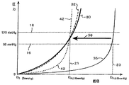
静脈移植体の拡張を抑止し得る設計とされた金属又は重合系外部構造体を使用することにより、これらの問題点の幾つかを解決しようと試みた者もいる。図1のグラフには、血管の直径対血圧が示されており、D0は、零圧力における血管の直径を示す。このグラフに示すように、線16は、人間の通常の心拡張期血圧、すなわち下の血圧(80mmHg)を示し、線18は、及び通常の心収縮期血圧、すなわち上の生理学的血圧(120mmHg)を示す。点21は、100mmHgにおける動脈の直径(DA)を示し、点23は、100mmHgの同一の圧力における静脈の直径(DV)を示す。ステント挿入無しの自然の動脈は、線32にて示した圧力負荷に反応し、また、ステント挿入無しの静脈は、線35にて示した同一の負荷に反応する。静脈移植体に対し既知のステントを使用する結果、線35は矢印38で示した方向に動き、その結果、圧力負荷を加えた静脈と非柔軟なステントとの組み合わせの応答性を示す、線42で示したおおよそのプロフィールとなる。このことは、過剰拡張を防止し、また、これに伴って多少の利点が生じるが、その結果、更なる不健常な合併症を招来する可能性がある。また、静脈−ステントの組み合わせ装置が、中間−移植領域における拡張及び内膜過形成の一部を制限することが判明している限り、これらは、吻合部における内膜過形成を防止することはできない。このことは、動脈の循環血管組織内に移植された静脈移植体にとって重大な問題となる可能性がある。これらの問題点を解消しようとする従来の試みは、これらの状況にて使用される静脈の影響を完全に認識していない。従って、その長期の開通性に影響を与えるであろう静脈−移植体の設計におけるファクタは、見逃されてきた。
Some have attempted to solve some of these problems by using metal or polymerized external structures designed to prevent the expansion of venous grafts. In the graph of FIG. 1, blood vessel diameter versus blood pressure is shown, where D 0 represents the blood vessel diameter at zero pressure. As shown in this graph,
適正な再造形における1つの重要な因子は、適正に周期的に伸延する因子である。当該出願人は、この着想を本発明の静脈−ステント移植体に組み込むことができる。同様の要領にて、血管平滑筋細胞内における血管内皮成長因子(VEGF)の役割は、好ましい動脈静脈−ステント移植体の設計にとって極めて重要であろう。低濃度のVEGFは、動脈の内腔内皮層を保存し且つ、修復する上で役目を果たすことができることが知られている。更に、VEGFの受容体KDRの作用は、周期的な伸延により行われることが示唆されている。当該出願人は、血管平滑筋細胞の生理学的伸延によりVEGF発現をアップレギュレーション(upregulation)する現象は、改良された制御可能な周期的伸延の特徴を有する静脈−ステント移植体を再設計する1つの理由であると考える。 One important factor in proper remodeling is the factor of proper periodic distraction. The applicant can incorporate this idea into the vein-stent implant of the present invention. In a similar manner, the role of vascular endothelial growth factor (VEGF) in vascular smooth muscle cells would be critical to the design of a preferred arterial vein-stent graft. It is known that low concentrations of VEGF can play a role in preserving and repairing the luminal endothelial layer of arteries. Furthermore, it has been suggested that the action of the VEGF receptor KDR is carried out by periodic distraction. Applicants believe that the phenomenon of up-regulating VEGF expression by physiological distraction of vascular smooth muscle cells is one of the redesigns of venous-stent grafts with improved controllable periodic distraction characteristics. I think that is the reason.
更なる考慮事項は、発現及び再造形中、特に、平滑筋細胞の方位に関して、かかる細胞の構造及び編成に対する引張り応力/歪みの影響である。より広い局所解剖学的意味において、このことは、移植体−受容体の直径が不適合となる位置における渦巻状の血流を誘発することを含んで、血液が既知の静脈移植体における局所的内膜過形成の生成に果たす役割にも関する。 A further consideration is the effect of tensile stress / strain on the structure and organization of such cells during expression and remodeling, particularly with respect to smooth muscle cell orientation. In a broader local anatomical sense, this includes inducing local blood flow in known venous grafts, including inducing spiral blood flow at locations where the graft-receptor diameter is mismatched. It also relates to the role played by the formation of membrane hyperplasia.
これらの考慮事項及び欠点は、健常な動脈のものを模擬するコンプライアンス特性を示す静脈移植体が提供される、本発明の色々な構造体及び方法にて対処することができる。所望の結果に少なくとも近づき得るよう動脈の半径方向への膨張及び収縮を模擬する要領にて移植体の半径方向への膨張及び収縮が許容され、この場合、静脈移植体、隣接する動脈端部又は断端へのその接続部分、及び隣接する動脈部分は、同様の要領にて膨張し且つ、収縮し、これにより吻合部のコンプライアンスの不適合を実質的に回避する傾向となる。このことは、支持体内に保持された静脈部分の管腔外面と係合する可撓性、弾性的で且つ、全体として管状の外部支持体を使用することを通して実現され、該支持体は、移植体に対し動脈のコンプライアンス特性を付与する機能を果たすように製造される。 These considerations and drawbacks can be addressed with the various structures and methods of the present invention in which a venous graft is provided that exhibits compliance characteristics that mimic those of a healthy artery. Radial expansion and contraction of the graft is allowed in a manner that simulates radial expansion and contraction of the artery so that it can at least approach the desired result, in which case the vein graft, adjacent arterial end or The connection to the stump, and the adjacent arterial portion, will expand and contract in a similar manner, thereby tending to substantially avoid incompatibility of the anastomosis. This is achieved through the use of a flexible, elastic and generally tubular outer support that engages the luminal surface of the venous portion held within the support, which support is implanted. Manufactured to function to impart arterial compliance characteristics to the body.
コンプライアンス特性
上述したように、コンプライアンスは、半径方向に向けた血管の直径の変化と血圧の所定の変化との比であり、以下に説明するコンプライアンス値は、動的生体外試験から得たものである。コンプライアンス値は、本明細所にて、通常の血液の範囲内、すなわち約80mmHgないし約120mmHgの範囲にて測定された血圧の100mmHg変化当たりの血管の内径の変化率として説明する。実験室において、使用を予定する管状支持体が配置される細長いバルーン構造体を使用することにより、コンプライアンスを測定することが便宜である。約37℃の蒸留水をバルーン内に圧送して、バルーンを拡張させ、また、バルーン内の圧力を通常の拍動の血液流を模擬し得るように分当たり約72サイクルの周期にて0mmHgと140mmHgの範囲にて周期的に作用させる。内部容積の変化は、0mmHgないし140mmHgの範囲にて測定し、圧力/容積データを提供する。このデータからバルーン単独の場合の方法を繰り返すことで得られる圧力データが得られ、また、得られる圧力/容積データから80ないし120mmHgの範囲にある管状支持体の内径の変化率を計算することができる。この半径方向コンプライアンス値は%/100mmHgとして表現することが便宜であろう。
Compliance characteristics As mentioned above, compliance is the ratio of the change in diameter of the blood vessel in the radial direction to a predetermined change in blood pressure, and the compliance values described below are obtained from dynamic in vitro tests. is there. Compliance values are described herein as the rate of change of the inner diameter of a blood vessel per 100 mmHg change in blood pressure measured in the normal blood range, ie, in the range of about 80 mmHg to about 120 mmHg. In the laboratory, it is convenient to measure compliance by using an elongated balloon structure on which the tubular support intended for use is placed. About 37 ° C. distilled water is pumped into the balloon to expand the balloon, and the pressure in the balloon is 0 mmHg at a cycle of about 72 cycles per minute to simulate normal pulsatile blood flow. Operate periodically in the range of 140 mmHg. The change in internal volume is measured in the range of 0 mmHg to 140 mmHg and provides pressure / volume data. From this data, pressure data obtained by repeating the method in the case of a balloon alone can be obtained, and the rate of change of the inner diameter of the tubular support in the range of 80 to 120 mmHg can be calculated from the obtained pressure / volume data. it can. It may be convenient to express this radial compliance value as% / 100 mmHg.
植え込んだ静脈移植体のコンプライアンスは、超音波技術を使用して生体内にて測定することができ、この場合、静脈移植体は断面図にて視覚化し、血圧が変化する血管寸法の変化を少なくとも1つ、通常、多数回の心臓サイクルにて記録する。静脈移植体の断面管腔面積は、1つの心臓サイクルについて最小の断面形態及び最大の断面形態に対し測定する。静脈移植体の管腔の最小断面形態は、心拡張期血圧と関係する一方、最大断面形態は、心収縮期圧力と関係する。心拡張期血圧及び心収縮期血圧に対する断面管腔面積の値を使用して、管腔直径の値及び静脈移植体のコンプライアンスを計算する。生体内にて測定された静脈移植体のコンプライアンス値は、実験室内にて測定されたコンプライアンス値よりもしばしば僅かに大きく、本明細所にて説明するコンプライアンス値は、上述した生体外測定値から得られた実験室値である。 The compliance of an implanted vein graft can be measured in vivo using ultrasound techniques, where the vein graft is visualized in a cross-sectional view and at least changes in blood vessel dimensions that change blood pressure. One, usually recorded in multiple cardiac cycles. The cross-sectional luminal area of the venous graft is measured for the minimum and maximum cross-sectional configurations for one cardiac cycle. The minimum cross-sectional configuration of the vein graft lumen is related to the diastolic blood pressure, while the maximum cross-sectional configuration is related to the systolic pressure. The values of cross-sectional luminal area for diastolic and systolic blood pressure are used to calculate luminal diameter values and venous graft compliance. The compliance value of vein grafts measured in vivo is often slightly larger than the compliance value measured in the laboratory, and the compliance values described here are obtained from the in vitro measurements described above. Is the laboratory value given.
図2は、自然の動脈構造体と本発明の補綴用静脈移植体構造体との関係を示すのに有用な血管組織の断面図である。動脈98の自然の外膜層95は、自然の動脈の物理的性質に寄与する2つの主要な組織型式、すなわちエラスチン及びコラーゲンから成っている。これら2つの柔軟な組織の成分の物理的性質は、以下の表1に掲げてある。
表1
柔軟な組織 弾性率(Pa) 最大歪み(%)
エラスチン 4x10⁵ 130
コラーゲン 1x10⁹ 2−4
上記の表に示すように、これら2つの柔軟な組織の型式は、物理的性質と大きく相違する。エラスチンは極めて弾性的であり、これと比較してコラーゲンは極めて硬い。これら2つの組織の型式は、外膜層内にて組み合わせて非直線状の弾性的応答性を生じさせる。図3に示すように、エラスチン101とコラーゲン104(より大きい歪みのときより大きい役割を果たす)の特徴の組み合わさった効果の結果、約80ないし120mmHgの範囲にて自然の動脈の生理学的圧力範囲内にある非直線状の応答曲線(負荷状態を参照番号135、非負荷状態を参照番号137で表示)となる。動脈のこの拍動性膨張及び収縮の特徴は、任意の補綴用移植体の精密な物理的コンプライアンスを必要とする、すなわち血圧の変化の下、拡張し且つ新形態をとる自然の動脈の力学及びタイミングを補綴用装置が正確に模擬することを必要とする。
FIG. 2 is a cross-sectional view of a vascular tissue useful for illustrating the relationship between a natural arterial structure and the prosthetic vein graft structure of the present invention. The natural
Table 1
Flexible tissue Elastic modulus (Pa) Maximum strain (%)
Elastin 4x10 5 130
Collagen 1x10 9 2-4
As shown in the table above, these two flexible tissue types differ significantly from physical properties. Elastin is extremely elastic, compared to collagen, which is extremely hard. These two tissue types combine in the outer membrane layer to produce a non-linear elastic response. As shown in FIG. 3, the combined effect of the features of
工学的観点から、本発明の静脈ステント移植体を製造するとき設計上の視点から見ると、次の関係が役立つであろう。
この場合、Cdはコンプライアンス、Pは血圧、Dは血管の直径、ΔDは心収縮期と心拡張期の間の直径の変化を表わす。
From an engineering point of view, the following relationship may be useful from a design point of view when manufacturing the venous stent graft of the present invention.
In this case, Cd is compliance, P is blood pressure, D is the diameter of the blood vessel, and ΔD is the change in diameter between systole and diastole.

血管の強度は、強度指数(β)として表わし、また、以下に表した曲率と直径との変化の測定値である。 The strength of the blood vessel is expressed as a strength index (β) and is a measurement of the change in curvature and diameter expressed below.
血管の関係した特徴は、強度の測定値と考えられる弾性率(K)であり、次式のように表わされる。 A related characteristic of blood vessels is an elastic modulus (K) that is considered to be a measured value of strength, and is expressed by the following equation.
この場合、Cはコンプライアンスである。一例として、直径方向コンプライアンスの項として、 In this case, C is compliance. As an example, as a term for diametric compliance,
図4には、上記の等式にて規定した弾性率(K)は心収縮期血圧と心拡張期血圧との間にて直線状目盛り(図4の左側のY軸)に示した圧力−直径曲線PD1の割線S1に比例することが示されている。割線S1の勾配(Psyst−Pdiast)(Dsyst−Ddiast)は、その圧力範囲における圧力−直径曲線PD1の勾配と良好に近似する。弾性率(K)に対する上記の等式から、弾性率(K)は、割線S1の勾配に等しくないが、ファクタDdiastolicだけ勾配に比例することが理解できる。コンプライアンス(Cd)は、弾性率(K)にほぼ比例し、従って、心拡張期血圧と心収縮期血圧との間の圧力−直径曲線PD1の割線S1の逆数にほぼ比例する。 In FIG. 4, the elastic modulus (K) defined by the above equation is the pressure − shown on the linear scale (Y axis on the left side of FIG. 4) between the systolic blood pressure and the diastolic blood pressure. It is shown to be proportional to the secant line S 1 of the diameter curve PD 1 . The slope of the secant line S 1 (P syst -P diast ) (D syst -D diast ) closely approximates the slope of the pressure-diameter curve PD 1 in that pressure range. From the above equation for elastic modulus (K), elastic modulus (K) is not equal to the slope of the secant S 1, it can be understood to be proportional to the slope by a factor D diastolic. Compliance (C d ) is approximately proportional to the modulus of elasticity (K) and is therefore approximately proportional to the reciprocal of the secant S 1 of the pressure-diameter curve PD 1 between diastolic and systolic blood pressure.
硬度指数(β)は、圧力−直径曲線を対数圧力目盛り(図4の右側のy軸)に示したとき、心拡張期血圧と心収縮期血圧との圧力−直径曲線PD2の割線S2に比例する。割線S2の勾配は、(lnPsyst−lnPdiast)/(Dsyst−Ddiast)であり、その圧力範囲における圧力−直径曲線PD2の勾配に良好に近似する。この場合にも、硬度指数(β)に対する上記の等式から、硬度指数(β)は割線S2の勾配に等しくないが、ファクタDdiastlicだけ該勾配に比例することが理解できる。 The hardness index (β) is a secant S 2 of the pressure-diameter curve PD 2 of the diastolic blood pressure and the systolic blood pressure when the pressure-diameter curve is shown on a logarithmic pressure scale (y axis on the right side of FIG. 4). Is proportional to Slope of the secant S 2 is, (lnP syst -lnP diast) a / (D syst -D diast), pressure in the pressure range - to good approximation to the slope of the diameter curve PD2. Again , from the above equation for the hardness index (β), it can be seen that the hardness index (β) is not equal to the slope of the secant S 2 , but is proportional to the slope by a factor D diagonal .
自然の人間の血管のコンプライアンスのデータは、血管の型式及び血管の年齢(すなわち、患者の年齢)により分類される。例えば、一般的な頚動脈は、約6.6%/100mmHgコンプライアンス値を有する。表面の大腿部動脈及び大腿部動脈に対する値は、6ないし10%/100mmHgである。しかし、伏在静脈の値は、約4.4%/100mmHgである一方、大動脈は、その位置に依存して、全体として約20ないし50%/100mmHgの範囲にある。また、体内の位置に従った移植体の長さを考慮しなければならず、移植体の長さが長さ方向に顕著に相違することは珍しいことではない。色々な動脈の直径は時間と共に変化し、この変化は、全体的なコンプライアンス値に大きく影響することも知られている。図1に戻ると、線80は、本発明の静脈移植体の特定の実施の形態が模倣(emulate)しようとする圧力−直径のデータを示し、この場合、自然の動脈のコンプライアンス特性(線32)は、正確に模擬される。
Natural human vascular compliance data is categorized by vessel type and vessel age (ie, patient age). For example, a typical carotid artery has a compliance value of about 6.6% / 100 mmHg. The value for the superficial femoral artery and femoral artery is 6 to 10% / 100 mmHg. However, the value of the saphenous vein is about 4.4% / 100 mmHg, while the aorta is generally in the range of about 20-50% / 100 mmHg, depending on its location. In addition, the length of the implant according to the position in the body must be taken into account, and it is not uncommon for the length of the implant to differ significantly in the length direction. It is also known that the diameter of various arteries changes with time, and this change greatly affects the overall compliance value. Returning to FIG. 1,
支持材料及び製造
半径方向に弾性的な支持体は、必要とされるコンプライアンスを有する管状構造体の形状となる能力を有する任意の生物学的に受容可能な材料にて製造することができる。ポリウレタン、ポリエチレンテレフタレート、ポリプロピレン及びポリテトラフルオロエチレンのような、重合系繊維を採用することができ、ステンレス鋼及びコバルト−クロム合金のような金属で出来たワイヤーを使用することを通じて良好な結果を得ることができる。ニチノール(nitinol)のような形状記憶合金で出来たワイヤーは、有益に使用することができる。形状記憶要素又はフィラメントは、次の表に例示された1つ又はより多くの形状記憶材料で出来たものとすることができ、これは、限定的なリストであるとみなすべきではないことが理解される。また、ポリマーは、生物分解性であるかどうかは自由であることを認識して、生体適合性を向上させ得るよう任意の金属又は金属合金は、ポリマーにて被覆することができる。
The support material and the radially elastic support can be made of any biologically acceptable material that has the ability to form a tubular structure with the required compliance. Polymeric fibers such as polyurethane, polyethylene terephthalate, polypropylene and polytetrafluoroethylene can be employed and good results are obtained through the use of wires made of metals such as stainless steel and cobalt-chromium alloys. be able to. Wires made of shape memory alloys such as nitinol can be beneficially used. It will be understood that the shape memory element or filament may be made of one or more shape memory materials as illustrated in the following table, and this should not be considered a limited list Is done. Also, any metal or metal alloy can be coated with the polymer to recognize that the polymer is biodegradable or not and can improve biocompatibility.
合金 ポリマー
Ag−Cd オリゴ(シグマ−カプロラクトン)ジメタクリレートと
N−アクリル酸ブチルとに基づく2成分システム
Au−Cd ポリウレタン
Cu−Al−Ni ポリノルボレネス(polynorborenes
)
Cu−Sn ポリ(エチレンオキシド)とポリ(エチレンテレフ
タレート)(EOET共ポリマー)とから成るポリ
(エーテルエステル)
Cu−Zn エチレンビニルアセテート共ポリマー
Cu−Zn−Si ポリスチレンポリブタジエン共ポリマー
Cu−Zn−Sn
Cu−Zn−Al
In−Ti
Ni−Al
Ni−Ti
Fe−Pt
Mn−Cu
Fe−Mn−Si
形状記憶合金に関して、その他の設計上、考慮すべき事項は、温度、異なる直径及び半径方向コンプライアンス、形状変態の寸法上の変化、及びワイヤーの太さを含む。全体として、形状記憶合金及び形状記憶ポリマーは、自動復元性応答を保証するため生理学的温度、すなわち37℃以下の変態温度を有することができる。好ましくは、変態温度は、室温以上であり、貯蔵目的のため形状記憶材料の補強部を冷凍する必要がないことを保証するようにする。このため、理想的な形状記憶変態温度は、21℃ないし37℃の範囲にあるものと考えられる。この遷移は、2方向又は1方向遷移の何れかであり、現在の好ましい実施の形態は、2方向遷移を含むものとする。この遷移温度範囲は、短い、すなわち0.5℃とするか、又は長い遷移温度範囲、すなわち10℃とし、ここにおいて、形状は、この温度範囲に亙って比例的に復帰する。例えば、25℃にて100%完全な所望の温度遷移の場合、この遷移が20℃にて開始するならば、このことは、5℃の温度範囲を提供することになろう。形状記憶材料が変態寸法変化を経験することに起因する半径方向直径の変化は、5%ないし30%の範囲にあることが好ましい。
Alloy polymer Ag-Cd oligo (sigma-caprolactone) dimethacrylate and
Two-component system based on N-butyl acrylate Au-Cd polyurethane Cu-Al-Ni polynorborenes
)
Cu-Sn poly (ethylene oxide) and poly (ethylene terf
Talate) (EOET copolymer)
(Ether ester)
Cu-Zn ethylene vinyl acetate copolymer Cu-Zn-Si polystyrene polybutadiene copolymer Cu-Zn-Sn
Cu-Zn-Al
In-Ti
Ni-Al
Ni-Ti
Fe-Pt
Mn-Cu
Fe-Mn-Si
With respect to shape memory alloys, other design considerations include temperature, different diameter and radial compliance, dimensional changes in shape transformation, and wire thickness. Overall, shape memory alloys and shape memory polymers can have a physiological temperature, that is, a transformation temperature of 37 ° C. or less to ensure an autorecoverable response. Preferably, the transformation temperature is above room temperature to ensure that the reinforcement of the shape memory material does not need to be frozen for storage purposes. For this reason, the ideal shape memory transformation temperature is considered to be in the range of 21 ° C. to 37 ° C. This transition is either a two-way or one-way transition, and the presently preferred embodiment shall include a two-way transition. This transition temperature range is short, ie 0.5 ° C. or a long transition temperature range, ie 10 ° C., where the shape returns proportionally over this temperature range. For example, for a desired
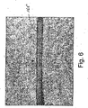
形状記憶合金を利用する管状支持体の1つの実施の形態は、図5及び図6に示されている。図5には、1つ又はより多くの形状記憶材料要素165にて出来た動脈補強用の管状支持体77が示されている。これらの要素は編み組みされているが、静脈の一部分の周りに配置し、動脈移植体を形成し得る設計とされた全体として管状の構造体となるように編んでもよい。この例において、形状記憶合金が採用されており、その理由は、温度誘発の相変化を受けるその能力ではなくて、そのいわゆる「超弾性」の性質のためであり、オーステナイトから応力誘発にらるマルテンサイトへの多少の相変化が生じることもある。図5において、編み組んだ管は、静脈部分を表わすものとして中空のプラスチックストロー上に配置されており、また、軸方向に圧縮されて直径を増大させている。図6に示すように、編み組んだ管を軸方向に伸ばすことにより、管の直径は縮小し、静脈部分に対する支持体を提供する。
One embodiment of a tubular support utilizing a shape memory alloy is shown in FIGS. FIG. 5 shows an arterial
図5及び図6に示した形状記憶編み組み材料は、その相変態性質のため使用されるならば、構造体内に静脈部分86を受け入れ得るよう容易に操作できる第一の形態(これは、マルテンサイト相とすることができる)と、静脈部分に対する支持体を提供し得るよう「記憶した」狭小な直径の形態を有する第二の形態(図6に示すように、これは、より高温度のオーストナイト相とすることができる)とにて供給することが可能である。構造体の内面170と静脈部分86の管腔外面175との接触は、図7にも示されている。形状記憶材料の弾性は、組成、焼戻し方法、ワイヤーの直径等を変化させることにより制御し、この材料にて出来た管状支持体が受容体動脈のコンプライアンス値を模擬し(静脈部分の最小の物理的値と組み合さったとき)、静脈移植体−動脈の相互作用を最適化し得るようにする。このコンプライアンスを模擬する特徴は、膨張、リコイル、タイミング及び組織の再造形の要素を含む。この例において、静脈−ステントのコンプライアンス値は、健常な自然の動脈の値を模擬し得るよう慎重に選ばれる。形状記憶ワイヤーは、これらの図面にて編み組んだものとして示される一方、これらのワイヤーは、編んだものでもよく、実際上、この編んだ形態は、特定の有利な効果を提供するものと考えられる。
The shape memory braided material shown in FIGS. 5 and 6 is a first form that can be easily manipulated to receive the
半径方向に弾性的な管状支持体は、ステンレス鋼、及びコバルト−クロム合金のような金属ワイヤーにて編むことができる。直径約25ないし150μmの範囲の金属ワイヤーは、編んだ支持体に適しており、35ないし50μmの範囲の直径が特に有用であるが、より大きい又はより小さい直径を所望に応じて採用することができる。編み組んだ管状支持体の場合、直径約37ないし約170μmの範囲の金属ワイヤーが適しているが、より大きい又はより小さい直径が採用できる。 The radially elastic tubular support can be knitted with metal wires such as stainless steel and cobalt-chromium alloys. Metal wires in the range of about 25 to 150 μm are suitable for braided supports, with diameters in the range of 35 to 50 μm being particularly useful, although larger or smaller diameters may be employed as desired. it can. For braided tubular supports, metal wires in the range of about 37 to about 170 μm in diameter are suitable, although larger or smaller diameters can be employed.
編み方法は、例えば、ラムニッティングマシーンコーポレーション(Lamb Knitting Machine Corporation)が製造したLX96編み機を使用して既知の方法により行うことができる。好ましい半径方向コンプライアンス及び管状寸法上の性質は、図21に示すように、大きいループと小さいループとを周方向に交互に配置することによりループを提供する要領にて管状支持体を編むことにより形成することができる。この図において、小さいループ250は、大きいループ251と共に周方向に交互に配置する状態に示されている。かかる交互に配置するループの寸法は、典型的に、各寸法の隣接するループが長手方向軸線内にて整合されるとき、管状支持体に沿って軸方向に伸びる長手方向縞として見える状態を示す。ループの閉止端の各々は、円形又は全体として四角形の形状とし或いは、その間にて変化させることができ、また、ループの側部は、外方に曲がり、平行にし又は内方に曲がるようにすることができる。後者の設計は、ばねのように作用し且つ、管状構造体の全体寸法を安定化させるのを助け、また、そのコンプライアンス特性を維持する点にてかなり有利な効果を有することが示されている。
The knitting method can be performed by a known method using, for example, an LX96 knitting machine manufactured by Lamb Knitting Machine Corporation. The preferred radial compliance and tubular dimensional properties are formed by knitting the tubular support in the manner of providing loops by alternating the large and small loops in the circumferential direction as shown in FIG. can do. In this figure, the
次に、編み又は編み組んだ管状支持体は、けん縮し、例えば、管状支持体の円周の周りを伸びる(すなわち、図17に示した要領にて)けん縮部を提供することができる。これを行う1つの方法は、軸方向溝付きのマンドレルを使用することにより行われ、このマンドレルは、管内に挿入され且つ、管の壁に対して外方に押し付けられ壁を相補的な形状の外側雌型鋳型に対して押し付け、編み又は編み組んだワイヤーを曲げて且つ、周方向けん縮部を形成し、該けん縮部は、支持体の軸方向に伸びるマンドレルの溝又は隆起したリッジの各々に起因する。 The braided or braided tubular support can then be crimped, for example, to provide a crimped portion that extends around the circumference of the tubular support (ie, as shown in FIG. 17). . One way to do this is by using an axial grooved mandrel, which is inserted into the tube and pressed outward against the wall of the tube to make the wall a complementary shape. Pressing against the outer female mold, bending the braided or braided wire and forming a circumferential crimp, the crimp of a mandrel groove or raised ridge extending in the axial direction of the support Due to each.
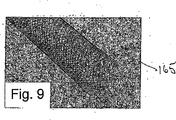
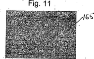
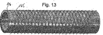
管状支持体に対して各種の金属又はポリマーを使用して柔軟な静脈移植体を幾つかの方法にて提供することができる。実施の形態は、編んだ形態にて有益に提供することができる。図8及び図9には、編み組んだ形態の材料165が示され、また、図10及び図11には、編んだ形態の材料165が示されている。管状支持体の物理的特徴は、編み又は編み組んだ構造体を構成する要素上に形成された整形し且つ、関係する構造体の型式により可能とすることができる。編み組み又は編んだ構造体とする前に、形成された斜めけん縮部(図12、図13に示す)と、丸味を付けたけん縮部(図14に示す)とを実現し得るよう材料165をけん縮するステップを含む技術は、許容可能な結果を提供するものと考えられる。予め編んだ形態に適したけん縮技術は、図15(斜めけん縮)、及び図16(丸形けん縮)にて示されている。編み組み又は編んだ形状記憶材料165の特定の性能特性を実現するための別の技術は、編み組み又は編んだ後に、すなわち編み組み又は編んだ後、けん縮を行うことである。図17には、編み組んだ形態にて形成された材料165の1つの実施の形態が示されており、また、この形態は、所望のけん縮特性を実現し得るよう玉冠状パターンを形成するため施される編み組んだ後のけん縮工程を有する。
A flexible vein graft can be provided in several ways using various metals or polymers for the tubular support. Embodiments can be beneficially provided in a knitted form. FIGS. 8 and 9 show a
けん縮角度及びピッチ密度は、管状支持体の現在の設計による特定の実施の形態における重要な可変値であろう。しかし、本発明の特定の有利な効果は、けん縮を使用せずに実現することが可能である。けん縮角度の範囲は、補強ワイヤー又は編み組んだ付設線に対し約10°ないし85°であることが好ましい。けん縮寸法は、0.01ないし5mmの長さにて相違するものとすることができる。編み組んだすなわちヘリカルなワイヤーは、静脈移植体の軸方向長さに対し約5ないし85°の範囲にて変化するピッチ角度を有することが望ましい。 The crimp angle and pitch density will be important variable values in certain embodiments according to the current design of the tubular support. However, certain advantageous effects of the present invention can be realized without using crimp. The crimp angle range is preferably about 10 ° to 85 ° with respect to the reinforcing wire or braided attachment line. The crimped dimensions can be different with a length of 0.01 to 5 mm. The braided or helical wire desirably has a pitch angle that varies in the range of about 5 to 85 ° relative to the axial length of the vein graft.
当該出願人は、編み組み又は編む前又はその後の何れにてけん縮することに関する特定のけん縮技術を開発した。例えば、編み組み後のけん縮において、既存の技術に従って材料の編み組み部が製造され、その後、編み組んだ後のけん縮工具を使用して肉眼的長手方向けん縮が管状メッシュに付与される。しかし、ステントの材料及び特定の形態に従って、編み組んだ管の編み組み後けん縮が十分なコンプライアンスを実現しないならば、その後に、代替的な方法が可能である。1つの例は、編み組み前けん縮を行ない、これにより、形状記憶材料の記憶をけん縮した形態に設定し、その後、編み組む前に、材料を真直ぐにすることである。このようにして、生理学的温度に曝されたとき、けん縮が誘発される。 The Applicant has developed specific crimping techniques relating to crimping either before or after braiding or knitting. For example, in crimping after braiding, a braided portion of material is manufactured according to existing techniques, and then a macroscopic crimp in the longitudinal direction is applied to the tubular mesh using a crimping tool after braiding. . However, depending on the stent material and the particular configuration, alternative methods are possible thereafter if the post-braid crimp of the braided tube does not provide sufficient compliance. One example is to perform pre-braid crimping, thereby setting the memory of the shape memory material to a crimped configuration, and then straightening the material before braiding. In this way, crimping is induced when exposed to physiological temperatures.
外部管状支持体は、健常な動脈特性に適合し又は模擬し、このため、受容体動脈の動脈圧力に順応させるべく静脈移植体の物理的及び幾何学的性質を調節する。従って、この結果、静脈移植体の管腔と受容体動脈とが実質的に適合し、静脈移植体と受容体動脈のコンプライアンスが実質的に適合し、静脈移植体と受容体動脈との半径対肉厚の比(r/wt)が実質的に適合する。上述したように、静脈−ステントのコンプライアンスを最適化することは、静脈−ステント移植体は、非直線状の補強に関して動脈の振舞いを模擬し、血圧の上昇に伴う直径の増大は、最高圧力にて「固定され」、次に、適宜な要領にて動的反跳を実証する。 The external tubular support adapts or simulates healthy arterial properties and thus adjusts the physical and geometric properties of the venous graft to accommodate the arterial pressure of the recipient artery. Therefore, this results in a substantial match between the lumen of the vein graft and the receptor artery, a substantial match between the vein graft and the receptor artery, and a radius pair between the vein graft and the receptor artery. The wall thickness ratio (r / wt) is substantially compatible. As noted above, optimizing venous-stent compliance means that the venous-stent implant mimics arterial behavior with respect to non-linear reinforcement, and the increase in diameter with increasing blood pressure is at maximum pressure. Then “fixed” and then demonstrate dynamic recoil in an appropriate manner.
編み又は編み組んだ管状支持体を利用する静脈移植体を全体として直角に又は貝殻状の形状にて端部同士を合わせた吻合部に適した角度にて切除するとき、支持体の端部はほつれを生ずるであろう(例えば、図17参照)。かかるほつれを解消するため、特定の方法及び構造が役立つ。1つの実施の形態において、生体吸収性又は生物分解性材料で出来た可調節リング210が図18に示すように、材料165の一部分の周りにて全体として周方向に且つ、外面217と接触する位置に配置される。リングの数は、必要に応じて変更することができる。リングの位置は、静脈及び管状支持体を切除する必要がある吻合部の位置に合わせて調節することができる。切除又は縫合はリングを通じて行ない、リングは所望に応じて、所定の時間に亙り吸収し又は分解するようにすることができる。
When excising a vein graft using a braided or braided tubular support at a right angle or at an angle suitable for the anastomosis where the ends are joined together in a shell-like shape, the end of the support is Fraying will occur (see, eg, FIG. 17). Certain methods and structures are useful to eliminate such fraying. In one embodiment, an
切除するとき、編み又は編み組んだ管状支持体のほつれを防止する構造体の別の実施の形態は、繊維メッシュに対しポリマー被覆を使用することである。この特徴はまた、ステントの継手及び要素の接触領域が接着するのを防止するとき、有利な効果を提供する。しかし、補強構造体として半径方向に柔軟な管状支持体を使用することは、静脈部分の外管腔面を支持体の向き合う内面に接着するというステップを有益に含む。この取り付け又は接続は、接着剤又は接続特性を有する糊又はその他の材料を使用して実現することができる。1つの実施の形態において、接着剤又は接続特性を有するフィブリン糊又はその他の材料を静脈(図20にて参照番号283にて例示)及び(又は)管状支持体の所定の部分に噴霧することができる。別の実施の形態は、材料を管状支持体の管腔面の所定の部分に配置し、これらの部分が静脈と接触するとき、接触接着及び(又は)接合特性を提供するステップを含む。しかし、糊又はその他の材料は、管状支持体の機能を阻止してはならない。管状支持体と静脈部分の管腔外面との接触は、支持体の長さに沿って妥当な程度に均一であり、静脈の管腔外壁に対する支持体の遥かに大きい力の領域が回避されるようにすることが望ましい。
Another embodiment of a structure that prevents fraying of the braided or braided tubular support when cutting is to use a polymer coating on the fiber mesh. This feature also provides an advantageous effect when preventing the joint and element contact areas of the stent from adhering. However, using a radially flexible tubular support as the reinforcing structure advantageously includes the step of adhering the outer luminal surface of the venous portion to the opposing inner surface of the support. This attachment or connection can be realized using glue or other material with connection properties. In one embodiment, a fibrin glue or other material having adhesive or connecting properties may be sprayed onto a vein (exemplified by
当該出願人は、半径方向に柔軟な管状支持体と静脈部分との組み立てを容易にする装置が必要とされることを更に認識した。かかるアプリケータは、ステント管腔を不鮮明にせず、また、静脈への挿入を容易にすることを許容することが望ましい。編み組んだ形態におけるように、長さ方向に圧縮することにより直径が増大する設計は、管状支持体が静脈上にて容易に滑動するのを許容することが更に認識される。図19には、編み組んだ支持体284を静脈86に取り付けるためアプリケータ279と組み合わせたこの着想が示されている。静脈をステントに接続する時点にて慎重に管理しなければならないこの長手方向への編み組み部の収縮現象(図5、図6に先に図示)は、上述したように、アプリケータ279の目標を実現するのに極めて有用であろう。このアプリケータはまた、ほつれ防止リング210を配置することも容易にする。1つの実施の形態において、アプリケータを使用する方法は、ステントを長手方向に収縮させる手段を提供するステップと、ステントを収縮位置に保持し、増大したステントの直径となるようにするステップと、静脈をステント管腔内に挿入するステップと、ステントが静脈の所望の部分上を滑動する迄、静脈を挿入すると同時に、ステントを長手方向に拡張させるステップとを備えている。更なる設計上の考慮事項は、ステントが長手方向に過剰に拡張し、又は収縮状態にて静脈に固定されず、所定の物理的なステントの特性が有効であるままにすることを保証しなければならないことである。
The applicant further recognized that there is a need for a device that facilitates assembly of a radially flexible tubular support and a venous portion. Such an applicator desirably does not blur the stent lumen and allows it to be easily inserted into a vein. It is further recognized that designs that increase in diameter by compressing longitudinally, such as in a braided configuration, allow the tubular support to slide easily over the vein. FIG. 19 illustrates this concept in combination with an applicator 279 to attach the
図20には、内部通路を有するアプリケータ281の表面の外面に沿って管状支持体185が受け入れられ、また、静脈部分86をアプリケータ通路内から通す間、管状支持体が静脈部分の管腔外面に押し付けられる実施の形態が示されている。アプリケータは、ソーダストローに類似する薄肉厚の管とすることができる。
In FIG. 20, a
支持体は、特定の所望のコンプライアンスと関係した所定の長さにて静脈に取り付けられることが重要である。長さを画成する支持体の特徴又はシステムは、所定の支持体の長さを保証する必要がある。このことは、編み組んだ支持体に関して特に真であり、また、支持体が軸方向に伸びる程度に半径方向弾性が依存する程度が少ない編んだ支持体にとって多分、重要性は低いであろう。 It is important that the support is attached to the vein at a predetermined length associated with a particular desired compliance. The feature or system of the support that defines the length needs to guarantee a given support length. This is especially true for braided supports and is probably less important for braided supports that are less dependent on radial elasticity to the extent that the support extends in the axial direction.
編み組んだ支持体において、また、程度は遥かに少ないものの、編んだ支持体において、コンプライアンス及び関係した物理的性質はピッチ角度を通じて支持体の長さに関係している。長さを変化させる結果、ピッチ角度及びコンプライアンスは変化する。しかし、支持体のコンプライアンスは、上述したように、通常の健常な受容体動脈のコンプライアンスを模擬するため、最適化される必須の特徴である。支持体を静脈部分に取り付けるとき、支持体を静脈に取り付けるため支持体が長手方向に収縮した後でさえ、所定の管状支持体の長さを正確に受け入れことが重要である。 In braided supports, and to a lesser extent, in braided supports, compliance and related physical properties are related to the length of the support through the pitch angle. As a result of changing the length, the pitch angle and compliance change. However, support compliance is an essential feature that is optimized to simulate normal healthy receptor artery compliance, as described above. When attaching the support to the venous portion, it is important to accurately receive the length of a given tubular support, even after the support has contracted longitudinally to attach the support to the vein.
編み組んだ支持体、また程度はより少ないものの、編んだ支持体の場合、支持体の軸方向長さは、例えば、管状支持体が望ましくなく軸方向に伸びるのを制限する軸方向に伸びる相対的に伸長不能な要素(例えば、図7の糸78)を使用することを通じて制御することができる。該糸は、支持メッシュを通じて織り且つ、溶接等によって糸が支持体の長さに沿って遭遇する色々なワイヤーに締結し、支持体が軸方向に延伸するとき、糸がぴんと張られる際、軸方向への伸び程度が糸によって制御されるようにする。更に、この特徴は、管状支持体の長さを適宜な長さ部分に分割し、各部分の許容された軸方向伸びがその内部の糸の部分により制御されることを可能にする。現在考えられるように、静脈部分は、上記に詳細に説明したように管状支持体内に鞘状に収納し、動脈を外科的に再交換するときに使用し得るよう形成される小さい静脈移植体部分を切除し、このように使用される静脈移植体は、同程度伸びる静脈及び管状支持体の端部を有するようにする。
In the case of a braided support, and to a lesser extent, a braided support, the axial length of the support is, for example, an axially extended relative to restricting the tubular support from undesirably extending in the axial direction. Can be controlled through the use of a non-extensible element (eg,
各種の全体的に管状の外部ワイヤメッシュ支持体は、編み組みし及び編むことにより金属ワイヤーから製造し、その一部はけん縮し、その他はけん縮せず、上記に概説した生体外の直径方向コンプライアンス試験を使用して各部分の直径方向コンプライアンスを測定した。測定したコンプライアンス値は、ワイヤー寸法、編み組み又は編みの緊密さ等を含む色々な可変値に依存するものとした。次のような値が得られた。 Various generally tubular outer wire mesh supports are manufactured from metal wire by braiding and knitting, some of which are crimped and others are not crimped, the in vitro diameter outlined above. A directional compliance test was used to measure the diametric compliance of each part. The measured compliance value was dependent on various variable values including wire dimensions, braid or tightness of the braid. The following values were obtained:
設計 コンプライアンス%/100mmHg
A 編み組み非けん縮 0.9
B 編み組みけん縮 5.6
C 編み組みけん縮 1.8
D 編み非けん縮 3.4
E 編みけん縮 7.9
F 編みけん縮 8.0
G 編み非けん縮 10−21
H 編み非けん縮 9−21
I 編み非けん縮 16−>30
J 編み非けん縮 >30
K 編み非けん縮 10−16
L 編み非けん縮 21−29
M 編み非けん縮 22−28
N 編み非けん縮 >30
O 編み非けん縮 10−15
P 編み非けん縮 9−11
Q 編み非けん縮 13−24
R 編み非けん縮 >30
本明細書に開示した静脈移植体を使用するための外科的方法が提案される。静脈補強構造体を配置する簡単な方法と見なすこともできる、この方法は、この例において、静脈切開法を行う間、柔軟な外部管状支持体を取り付けるステップを含む。多くの場合、静脈切開部は、通常、外科医が未だ手術の準備段階にある時点にてアシスタントによって行われる外科的処置の標準的一部とみなされる。
Design Compliance% / 100mmHg
A Braided non-crimped 0.9
B Braided crimp 5.6
C Braided crimp 1.8
D Knitted non-crimp 3.4
E knitting crimp 7.9
F knitting crimp 8.0
G Knitted non-crimp 10-21
H knitting non-crimp 9-21
I Knitting non-crimp 16-> 30
J Knitted non-crimp> 30
K knitting non-crimp 10-16
L Knitted non-crimp 21-29
M Knitted non-crimp 22-28
N Knitted non-crimp> 30
O Knitted non-crimp 10-15
P knitting non-crimp 9-11
Q Knitting non-crimp 13-24
R Knitted non-crimp> 30
Surgical methods for using the vein grafts disclosed herein are proposed. This method, which can also be considered as a simple method of placing the vein reinforcement structure, in this example includes attaching a flexible external tubular support during the phlebotomy. In many cases, a phlebotomy is usually considered a standard part of a surgical procedure performed by an assistant when the surgeon is still in preparation for surgery.
1つの実施の形態において、最初のステップは、伏在静脈を切開し且つ、分離させるステップを含む。伏在静脈は、標準的な要領にて切開し自由とし、該静脈はその支管を結紮し且つ、切除する間、所要位置に止まるようにする。この第二のステップは、静脈壁の漏洩の可能性を試験するステップを含む。漏洩の可能性について隔離した伏在静脈を試験するため、静脈は通常、末端方向にカニューレが挿入され、基端が閉塞している間、低温のヘパリンを加えた血液を注入する。注射器によるこの静脈の拡張(古くからの技術を使用して)は、350mmHg以内の圧力を発生させ、また、しばしば静脈壁の外傷性損傷の主要な原因となる。このため、静脈カニューレと注射器との間に圧力制限機構を設けることができる。静脈壁の漏洩箇所は、修復のため自由にアクセス可能である必要があるため、外部管状支持体はまだ取り付けることができない。このため、過剰拡延保護部は静脈の周りに配置されず、懸念される全ての漏洩を検出するのに適したレベルであるが、例えば、1つの実施の形態において、静脈に対する最高拡張圧力前の15mmHgのような、許容し得ない損傷を生じさせると考えられるものより低いレベルに拡張圧力を制限することが必要となる。当該出願人の発明の組織の再造形機能は、漏洩試験の重要性及び最も慎重に行った漏洩試験の間でさえ、静脈内の内膜層への損傷の現実性を考えれば、より重要となる。 In one embodiment, the initial step includes incising and separating the saphenous vein. The saphenous vein is incised and freed in a standard manner so that the vein remains in place while the branch is ligated and resected. This second step involves testing the possibility of venous wall leakage. To test isolated saphenous veins for possible leaks, the veins are typically infused with cold heparinized blood while the proximal end is occluded and the proximal end occluded. This venous dilation by syringe (using old technology) generates pressures within 350 mm Hg and is often a major cause of traumatic damage to the venous wall. For this reason, a pressure limiting mechanism can be provided between the venous cannula and the syringe. Since the leak point in the vein wall needs to be freely accessible for repair, the outer tubular support cannot be attached yet. For this reason, the over-extension protector is not placed around the vein and is at a level suitable for detecting all the leaks of concern, but in one embodiment, for example, before the maximum dilation pressure on the vein. It is necessary to limit the expansion pressure to a level lower than that which would cause unacceptable damage, such as 15 mm Hg. The tissue remodeling function of the applicant's invention is more important given the importance of leak testing and even the most careful leak testing, given the reality of the damage to the venous intima layer. Become.
次のステップは、採取した静脈部分及び本発明の外部管状支持体を組み立てるステップを含む。このステップにおいて、管状支持体(本明細書にて、典型的に編み支持体)は、その内部に静脈部分が配置された管又はストロー状アプリケータに取り付ける。図20参照。次に、ストローを軸方向に除去し、支持体及び静脈が接触したままにて静脈移植体を形成するようにする。上述したように、長さを制限する中央糸又はその他の手段を使用して管状支持体の過剰の拡延が防止される。次に、必要とされるように、120mmHgの動脈血圧下にて静脈部分を拡張させ、該静脈部分が管状支持体の管腔内面と接触するようにする。特定の実施の形態において、管状支持体を静脈に固定する接着剤は、内部圧力が加えられないとき、外科的方法を行う間、静脈が潰れないことを保証するであろう。この場合にも、このことは、上述した目的を実現する幾つかの方法の1つである(限定的ではなく)ことを認識すべきである。 The next step involves assembling the harvested venous portion and the outer tubular support of the present invention. In this step, the tubular support (here typically a braided support) is attached to a tube or straw applicator with a vein portion disposed therein. See FIG. The straw is then removed axially to form a venous graft while the support and vein are in contact. As noted above, excessive lengthening of the tubular support is prevented using a central thread or other means of limiting length. Next, as required, the venous portion is expanded under arterial blood pressure of 120 mm Hg so that the venous portion contacts the luminal surface of the tubular support. In certain embodiments, the adhesive that secures the tubular support to the vein will ensure that the vein does not collapse during the surgical procedure when internal pressure is not applied. Again, it should be recognized that this is one (but not limited) of several ways of achieving the objectives described above.
次の手順は、この時点又は手術を行う間の別の時点において、行われる。外部ほつれ防止リング、すなわちカフの1つを静脈の端部まで摺動させ、典型的な二重S字形切断線を使用して最初の吻合のため端部を準備する。薄いカフは、管状支持体のほつれを防止し、また、静脈組織及び管状支持体に対し均一性を与え、この均一性は、端部と側部を合わせた要領にて静脈を受容体動脈に縫い付ける外科的方法を遥かに容易にする。次に、別の薄いほつれ防止リングをアプリケータから順序的な移植体に対する側部同士を合わせた吻合が行われる箇所又は静脈が適宜な移植体の長さに切除される箇所の何れかの位置まで下方に摺動させる。最初の静脈に止るカフ半体は、基端受容体動脈に対するこの吻合過程を遥かに容易にする。例えば、冠状動脈バイパス移植体の場合、カフの他の半体により保護された残りの静脈の端部は、次の末端の移植体の吻合のために使用する。 The next procedure is performed at this point or at another point during the operation. Slide one of the anti-fray rings or cuffs to the end of the vein and prepare the end for the first anastomosis using a typical double sigmoidal cutting line. The thin cuff prevents fraying of the tubular support and also provides uniformity to the venous tissue and the tubular support, which is the end-to-side combination of the veins into the recipient artery. Makes the surgical method of sewing much easier. Next, another thin fray-preventing ring, either from the applicator where the anastomosis of the side-to-side grafts is performed or where the vein is cut to the appropriate graft length Slide down until A cuff half that stops in the first vein makes this anastomosis process for the proximal receptor artery much easier. For example, in the case of a coronary artery bypass graft, the end of the remaining vein protected by the other half of the cuff is used for anastomosis of the next distal graft.
構造体は、設計の点のみならず、使用する材料の範囲にても益々複雑になるに伴い、純然たる分析的方法では、かかる構造体の振舞いを説明することができなくなりつつある。受容体に対して本明細書に記載した型式の血管移植体を正確に適合させる科学的に困難な課題のため、分析的方法は、多少時代遅れとなっている。しかし、特定の旧式の道具、特にカットアンドトライ方法により通常の健常な組織の物理的必要条件及び動的コンプライアンスを模擬する補綴血管移植体を開発することが可能となっており、このカットアンドトライ方法において、管状支持体の材料又は構造体に対し漸増的変化が加えられ、そのコンプライアンス特性を修正し、また、得られる特性を使用して更なる変化を導く。特定の特徴のため、実験データ又は構成方程式及び算術的解析方法を使用することができる。これと代替的に、例えば、特定のその他の道具と共に、連続体力学を活用する有限要素モデル及び方法のような道具による数値モデリングを使用することにより、このレベルの特注化が実現可能となる。 As structures become increasingly complex not only in terms of design but also in the range of materials used, pure analytical methods are no longer able to explain the behavior of such structures. Analytical methods are somewhat obsolete due to the scientifically difficult task of accurately adapting a vascular graft of the type described herein to the receptor. However, it is possible to develop prosthetic vascular grafts that simulate the physical requirements and dynamic compliance of normal healthy tissue with certain older tools, especially cut-and-try methods. In the method, incremental changes are made to the material or structure of the tubular support, modifying its compliance characteristics and using the resulting characteristics to guide further changes. For specific features, experimental data or constitutive equations and arithmetic analysis methods can be used. Alternatively, this level of customization can be achieved, for example, by using numerical modeling with tools such as finite element models and methods that utilize continuum mechanics, along with certain other tools.
本明細書に記載した本発明の実施の形態は、現在好ましいものであるが、本発明の精神及び範囲から逸脱せず、色々な形態変更例及び改良を加えることが可能である。本発明の範囲は、特許請求の範囲により示され、均等物の意義及び範囲に属する全ての変更は本明細書に包含することを意図するものである。 While the embodiments of the invention described herein are presently preferred, various changes and modifications can be made without departing from the spirit and scope of the invention. The scope of the invention is indicated by the appended claims, and all changes that come within the meaning and range of equivalents are intended to be embraced herein.
Claims (8)
該管状の外部静脈支持体は、当該支持体の周方向に交互に配置されたループを有する横糸を管状に編んだパターンに、単一の超弾性のワイヤ又は繊維で形成され、3ないし30%/100mmHgの範囲の非直線状のコンプライアンスを提供する要領にて弾性的に半径方向に膨張可能である、外科用インプラント。An external venous support in the form of an elastic tubular braided wire or fiber mesh is supportably contacted with the luminal surface of the venous portion to form a venous graft that mimics the compliance characteristics of a healthy artery A surgical implant having
The tubular external venous support is formed of a single superelastic wire or fiber in a pattern in which wefts having loops arranged alternately in the circumferential direction of the support are knitted in a tubular shape, and is 3 to 30%. Surgical implant that is elastically radially expandable in a manner that provides non-linear compliance in the range of / 100 mmHg.
前記ワイヤ又は繊維のメッシュは金属ワイヤーにて出来ている、外科用インプラント。The surgical implant of claim 1, wherein
Surgical implant, wherein the wire or fiber mesh is made of metal wire.
前記金属ワイヤーは、ステンレス鋼又はコバルトクロム合金で出来ている、外科用インプラント。The surgical implant of claim 2, wherein
The metal wire is a surgical implant made of stainless steel or cobalt chrome alloy.
前記金属ワイヤーは形状記憶合金である、外科用インプラント。The surgical implant of claim 2 , wherein
The surgical implant, wherein the metal wire is a shape memory alloy.
前記繊維メッシュは重合系である、外科用インプラント。The surgical implant of claim 1, wherein
The surgical implant, wherein the fiber mesh is a polymerized system.
前記メッシュは、静脈部分の管腔外面に接合される、外科用インプラント。The surgical implant of claim 1, wherein
The surgical implant wherein the mesh is joined to the luminal surface of the venous portion.
前記管状繊維メッシュはけん縮した繊維で出来ている、外科用インプラント。The surgical implant of claim 1, wherein
A surgical implant wherein the tubular fiber mesh is made of crimped fibers.
前記管状繊維メッシュは、前記管状メッシュに形成された後、けん縮した繊維にて出来ている、外科用インプラント。The surgical implant of claim 7, wherein
A surgical implant wherein the tubular fiber mesh is made of crimped fibers after being formed into the tubular mesh.
Applications Claiming Priority (3)
| Application Number | Priority Date | Filing Date | Title |
|---|---|---|---|
| US46622603P | 2003-04-28 | 2003-04-28 | |
| US60/466,226 | 2003-04-28 | ||
| PCT/US2004/012973 WO2004096095A2 (en) | 2003-04-28 | 2004-04-28 | Compliant venous graft |
Publications (3)
| Publication Number | Publication Date |
|---|---|
| JP2006524556A JP2006524556A (en) | 2006-11-02 |
| JP2006524556A5 JP2006524556A5 (en) | 2007-06-14 |
| JP4692902B2 true JP4692902B2 (en) | 2011-06-01 |
Family
ID=33418355
Family Applications (1)
| Application Number | Title | Priority Date | Filing Date |
|---|---|---|---|
| JP2006513369A Expired - Fee Related JP4692902B2 (en) | 2003-04-28 | 2004-04-28 | Flexible vein graft |
Country Status (8)
| Country | Link |
|---|---|
| US (3) | US8057537B2 (en) |
| EP (2) | EP2335648A1 (en) |
| JP (1) | JP4692902B2 (en) |
| AT (1) | ATE531338T1 (en) |
| CA (1) | CA2523812C (en) |
| ES (1) | ES2375566T3 (en) |
| WO (1) | WO2004096095A2 (en) |
| ZA (1) | ZA200508920B (en) |
Families Citing this family (64)
| Publication number | Priority date | Publication date | Assignee | Title |
|---|---|---|---|---|
| US10327880B2 (en) | 2000-04-14 | 2019-06-25 | Attenuex Technologies, Inc. | Attenuation device for use in an anatomical structure |
| US6682473B1 (en) | 2000-04-14 | 2004-01-27 | Solace Therapeutics, Inc. | Devices and methods for attenuation of pressure waves in the body |
| US7540876B2 (en) | 2000-04-14 | 2009-06-02 | Attenuex Technologies, Inc. | Pressure attenuation device |
| EP1414369A2 (en) * | 2001-07-27 | 2004-05-06 | Medtronic, Inc. | Adventitial fabric reinforced porous prosthetic graft |
| US20050131520A1 (en) | 2003-04-28 | 2005-06-16 | Zilla Peter P. | Compliant blood vessel graft |
| EP2335648A1 (en) | 2003-04-28 | 2011-06-22 | Kips Bay Medical, Inc. | Compliant venous graft |
| US7998188B2 (en) | 2003-04-28 | 2011-08-16 | Kips Bay Medical, Inc. | Compliant blood vessel graft |
| NZ527025A (en) * | 2003-07-16 | 2007-01-26 | David Peter Shaw | Prosthetic valves for medical application |
| US20060259137A1 (en) | 2003-10-06 | 2006-11-16 | Jason Artof | Minimally invasive valve replacement system |
| WO2006054968A1 (en) * | 2004-11-12 | 2006-05-26 | Medtronic, Inc. | Compliant blood vessel graft |
| EP1839601A1 (en) * | 2006-03-30 | 2007-10-03 | Levitronix LLC | Self-expanding cannula |
| EP1839600A1 (en) * | 2006-03-30 | 2007-10-03 | Levitronix LLC | Expandable conduit-guide |
| US9237945B2 (en) | 2007-01-30 | 2016-01-19 | University of Pittsburgh—of the Commonwealth System of Higher Education | Bioerodible wraps and uses therefor |
| EP2249742B1 (en) * | 2008-02-14 | 2017-06-21 | RegenMed (Cayman) Ltd. | Tissue engineering scaffolds |
| US8353814B2 (en) * | 2008-10-09 | 2013-01-15 | Kips Bay Medical, Inc. | Apparatus and method for mounting an external scaffold to a vascular graft |
| JP5855460B2 (en) | 2008-11-24 | 2016-02-09 | ヴァスキュラー グラフト ソリューションズ リミテッド | External stent |
| EP2367503A1 (en) | 2008-11-25 | 2011-09-28 | AttenueX Technologies, Inc. | Implant with high vapor pressure medium |
| AU2010315417B2 (en) | 2009-10-28 | 2016-12-15 | Neograft Technologies, Inc. | Bioerodible wraps and uses therefor |
| CA2782357C (en) | 2009-11-30 | 2018-06-05 | Endospan Ltd. | Multi-component stent-graft system for implantation in a blood vessel with multiple branches |
| EP2332499B1 (en) * | 2009-12-11 | 2016-01-27 | Biotronik VI Patent AG | Endoprosthesis |
| US8992594B2 (en) | 2009-12-16 | 2015-03-31 | Neograft Technologies, Inc. | Graft devices and methods of use |
| EP2519188A4 (en) | 2009-12-31 | 2017-03-22 | Neograft Technologies, Inc. | Graft devices and methods of fabrication |
| WO2011130579A1 (en) | 2010-04-14 | 2011-10-20 | Abbott Cardiovascular Systems Inc. | Intraluminal scaffold and method of making and using same |
| US8579964B2 (en) | 2010-05-05 | 2013-11-12 | Neovasc Inc. | Transcatheter mitral valve prosthesis |
| WO2012012407A2 (en) | 2010-07-19 | 2012-01-26 | Neograft Technologies, Inc. | Graft devices and methods of use |
| WO2012085807A1 (en) * | 2010-12-19 | 2012-06-28 | Inspiremd Ltd. | Stent with sheath and metal wire retainer |
| WO2012084007A1 (en) * | 2010-12-20 | 2012-06-28 | Graftcraft I Göteborg Ab | Removable stent and method of production |
| US9656417B2 (en) | 2010-12-29 | 2017-05-23 | Neograft Technologies, Inc. | System and method for mandrel-less electrospinning |
| EP2663265A4 (en) | 2011-01-14 | 2016-05-25 | Neograft Technologies Inc | Apparatus for creating graft devices |
| US9526638B2 (en) | 2011-02-03 | 2016-12-27 | Endospan Ltd. | Implantable medical devices constructed of shape memory material |
| EP2680788A4 (en) | 2011-03-02 | 2014-12-10 | Endospan Ltd | Reduced-strain extra- vascular ring for treating aortic aneurysm |
| WO2012143925A1 (en) | 2011-04-18 | 2012-10-26 | Vascular Graft Solutions Ltd | Devices and methods for deploying implantable sleeves over blood vessels |
| WO2012143922A1 (en) * | 2011-04-18 | 2012-10-26 | Vascular Graft Solutions Ltd | External support for elongated bodily vessels |
| US9308087B2 (en) | 2011-04-28 | 2016-04-12 | Neovasc Tiara Inc. | Sequentially deployed transcatheter mitral valve prosthesis |
| US9554897B2 (en) | 2011-04-28 | 2017-01-31 | Neovasc Tiara Inc. | Methods and apparatus for engaging a valve prosthesis with tissue |
| US9254209B2 (en) | 2011-07-07 | 2016-02-09 | Endospan Ltd. | Stent fixation with reduced plastic deformation |
| WO2013016349A2 (en) | 2011-07-25 | 2013-01-31 | Neograft Technologies, Inc. | Vessel treatment methods and devices for use in a graft device |
| WO2013030818A2 (en) * | 2011-08-28 | 2013-03-07 | Endospan Ltd. | Stent-grafts with post-deployment variable axial and radial displacement |
| EP2770952A4 (en) * | 2011-10-25 | 2015-07-29 | Neograft Technologies Inc | Graft device with adhered fiber matrix |
| WO2013090337A1 (en) | 2011-12-13 | 2013-06-20 | Neograft Technologies, Inc. | System and atraumatic mandrel for creating graft devices |
| US9345573B2 (en) | 2012-05-30 | 2016-05-24 | Neovasc Tiara Inc. | Methods and apparatus for loading a prosthesis onto a delivery system |
| US8894563B2 (en) | 2012-08-10 | 2014-11-25 | Attenuex Technologies, Inc. | Methods and systems for performing a medical procedure |
| CN105007860B (en) | 2013-01-08 | 2017-05-10 | 恩多斯潘有限公司 | Minimization of stent-graft migration during implantation |
| US9668892B2 (en) | 2013-03-11 | 2017-06-06 | Endospan Ltd. | Multi-component stent-graft system for aortic dissections |
| US9572665B2 (en) | 2013-04-04 | 2017-02-21 | Neovasc Tiara Inc. | Methods and apparatus for delivering a prosthetic valve to a beating heart |
| WO2015012785A1 (en) * | 2013-07-22 | 2015-01-29 | Motorola Solutions, Inc. | Display system with antistatic housing for a communication device |
| US10603197B2 (en) | 2013-11-19 | 2020-03-31 | Endospan Ltd. | Stent system with radial-expansion locking |
| US11000285B2 (en) * | 2013-12-17 | 2021-05-11 | 3Dt Holdings, Llc | Luminal grafts and methods of making and using the same |
| CA2967904C (en) | 2014-12-18 | 2023-01-10 | Endospan Ltd. | Endovascular stent-graft with fatigue-resistant lateral tube |
| US11471586B2 (en) | 2015-12-15 | 2022-10-18 | University Of Massachusetts | Negative pressure wound closure devices and methods |
| CA3007670A1 (en) | 2016-01-29 | 2017-08-03 | Neovasc Tiara Inc. | Prosthetic valve for avoiding obstruction of outflow |
| WO2018090148A1 (en) | 2016-11-21 | 2018-05-24 | Neovasc Tiara Inc. | Methods and systems for rapid retraction of a transcatheter heart valve delivery system |
| WO2018107092A1 (en) * | 2016-12-09 | 2018-06-14 | The Regents Of The University Of California | Surface-functionalized tubular structures, and methods of making and using the same |
| CA3073834A1 (en) | 2017-08-25 | 2019-02-28 | Neovasc Tiara Inc. | Sequentially deployed transcatheter mitral valve prosthesis |
| US20210077284A1 (en) * | 2018-01-30 | 2021-03-18 | Nanyang Technological University | Scaffold for vascular prothesis and a method of fabricating thereof |
| WO2019178579A1 (en) | 2018-03-16 | 2019-09-19 | Boston Scientific Scimed, Inc. | Devices for vein closure |
| WO2020072717A1 (en) * | 2018-10-05 | 2020-04-09 | Board Of Regents Of The University Of Nebraska | Bypass graft |
| EP3876870B1 (en) | 2018-11-08 | 2023-12-20 | Neovasc Tiara Inc. | Ventricular deployment of a transcatheter mitral valve prosthesis |
| EP3920771A4 (en) | 2019-02-07 | 2022-11-02 | Solace Therapeutics, Inc. | Pressure attenuation device |
| CA3135753C (en) | 2019-04-01 | 2023-10-24 | Neovasc Tiara Inc. | Controllably deployable prosthetic valve |
| US11491006B2 (en) | 2019-04-10 | 2022-11-08 | Neovasc Tiara Inc. | Prosthetic valve with natural blood flow |
| AU2020279750B2 (en) | 2019-05-20 | 2023-07-13 | Neovasc Tiara Inc. | Introducer with hemostasis mechanism |
| EP3986332A4 (en) | 2019-06-20 | 2023-07-19 | Neovasc Tiara Inc. | Low profile prosthetic mitral valve |
| US11291565B1 (en) | 2021-04-22 | 2022-04-05 | Vascular Graft Solutions Ltd. | Asymmetric external support for stabilizing a vein graft used in a coronary arterial bypass graft (CABG) procedure, and applications thereof |
Family Cites Families (109)
| Publication number | Priority date | Publication date | Assignee | Title |
|---|---|---|---|---|
| US3337673A (en) | 1958-07-31 | 1967-08-22 | Us Catheter & Instr Corp | Uniformly corrugated prosthesis and process of making same |
| US3626947A (en) | 1970-02-19 | 1971-12-14 | Charles Howard Sparks | Method and apparatus for vein and artery reenforcement |
| US3797485A (en) | 1971-03-26 | 1974-03-19 | Alza Corp | Novel drug delivery device for administering drug into blood circulation in blood vessel |
| US3974526A (en) | 1973-07-06 | 1976-08-17 | Dardik Irving I | Vascular prostheses and process for producing the same |
| US4173689A (en) * | 1976-02-03 | 1979-11-06 | University Of Utah | Synthetic polymer prosthesis material |
| EP0130401B1 (en) | 1983-06-06 | 1989-05-17 | Kanegafuchi Kagaku Kogyo Kabushiki Kaisha | Artificial vessel and process for preparing the same |
| EP0128501B1 (en) | 1983-06-06 | 1989-03-29 | Kanegafuchi Kagaku Kogyo Kabushiki Kaisha | Artificial vessel and process for preparing the same |
| FR2556210B1 (en) * | 1983-12-08 | 1988-04-15 | Barra Jean Aubert | VENOUS PROSTHESIS AND PROCESS FOR PRODUCING THE SAME |
| US4652264A (en) | 1985-04-25 | 1987-03-24 | American Cyanamid Company | Prosthetic tubular article |
| JPS6244260A (en) * | 1985-08-23 | 1987-02-26 | 鐘淵化学工業株式会社 | Artificial blood vessel excellent in openability |
| US4725273A (en) * | 1985-08-23 | 1988-02-16 | Kanegafuchi Kagaku Kogyo Kabushiki Kaisha | Artificial vessel having excellent patency |
| DE3640745A1 (en) | 1985-11-30 | 1987-06-04 | Ernst Peter Prof Dr M Strecker | Catheter for producing or extending connections to or between body cavities |
| US4956178A (en) * | 1988-07-11 | 1990-09-11 | Purdue Research Foundation | Tissue graft composition |
| US4969896A (en) | 1989-02-01 | 1990-11-13 | Interpore International | Vascular graft prosthesis and method of making the same |
| US5609626A (en) | 1989-05-31 | 1997-03-11 | Baxter International Inc. | Stent devices and support/restrictor assemblies for use in conjunction with prosthetic vascular grafts |
| JPH03260178A (en) | 1990-03-06 | 1991-11-20 | Showa Shell Sekiyu Kk | Production of water-absorbing and water-retaining flexible cloth |
| CA2045222A1 (en) * | 1990-07-12 | 1992-01-13 | Norman R. Weldon | Composite biosynthetic graft |
| US5320100A (en) | 1991-09-16 | 1994-06-14 | Atrium Medical Corporation | Implantable prosthetic device having integral patency diagnostic indicia |
| US5366504A (en) | 1992-05-20 | 1994-11-22 | Boston Scientific Corporation | Tubular medical prosthesis |
| US5662713A (en) * | 1991-10-09 | 1997-09-02 | Boston Scientific Corporation | Medical stents for body lumens exhibiting peristaltic motion |
| JPH07505316A (en) | 1992-03-31 | 1995-06-15 | ボストン サイエンティフィック コーポレーション | medical wire |
| US7101392B2 (en) | 1992-03-31 | 2006-09-05 | Boston Scientific Corporation | Tubular medical endoprostheses |
| US5628782A (en) | 1992-12-11 | 1997-05-13 | W. L. Gore & Associates, Inc. | Method of making a prosthetic vascular graft |
| US5716395A (en) | 1992-12-11 | 1998-02-10 | W.L. Gore & Associates, Inc. | Prosthetic vascular graft |
| WO1994021197A1 (en) | 1993-03-25 | 1994-09-29 | C.R. Bard, Inc. | Vascular graft |
| US5913894A (en) | 1994-12-05 | 1999-06-22 | Meadox Medicals, Inc. | Solid woven tubular prosthesis |
| US5723004A (en) | 1993-10-21 | 1998-03-03 | Corvita Corporation | Expandable supportive endoluminal grafts |
| DE4340755C1 (en) * | 1993-11-30 | 1995-06-29 | Zurbruegg Heinz R | Vascular prosthesis |
| KR100342025B1 (en) | 1994-02-07 | 2003-03-15 | 가부시키가이샤 이가키 이료 세케이 | Stent Device and Stent Supply System |
| US5478349A (en) | 1994-04-28 | 1995-12-26 | Boston Scientific Corporation | Placement of endoprostheses and stents |
| US5584876A (en) | 1994-04-29 | 1996-12-17 | W. L. Gore & Associates, Inc. | Cell excluding sheath for vascular grafts |
| CA2147547C (en) | 1994-08-02 | 2006-12-19 | Peter J. Schmitt | Thinly woven flexible graft |
| ATE285813T1 (en) * | 1994-10-17 | 2005-01-15 | Igaki Iryo Sekkei Kk | STENT WITH DRUG DELIVERY |
| US5681345A (en) | 1995-03-01 | 1997-10-28 | Scimed Life Systems, Inc. | Sleeve carrying stent |
| US5556414A (en) * | 1995-03-08 | 1996-09-17 | Wayne State University | Composite intraluminal graft |
| GB2298577B (en) | 1995-03-09 | 1999-02-17 | Univ Bristol | Arteriovenous bypass grafting |
| US6264684B1 (en) | 1995-03-10 | 2001-07-24 | Impra, Inc., A Subsidiary Of C.R. Bard, Inc. | Helically supported graft |
| US6053943A (en) | 1995-12-08 | 2000-04-25 | Impra, Inc. | Endoluminal graft with integral structural support and method for making same |
| RU2102016C1 (en) | 1995-07-07 | 1998-01-20 | Московский государственный институт стали и сплавов (технологический университет) | Device for extravasal correction of function of main vein valves |
| WO1996038090A1 (en) | 1995-06-01 | 1996-12-05 | Moskovsky Gosudarstvenny Institut Stali I Splavov Tekhnologichesky Universitet | Method of extravascular correction of the function of incompetent vein valves and an extravascular corrector for that purpose |
| US5900433A (en) | 1995-06-23 | 1999-05-04 | Cormedics Corp. | Vascular treatment method and apparatus |
| US6428571B1 (en) | 1996-01-22 | 2002-08-06 | Scimed Life Systems, Inc. | Self-sealing PTFE vascular graft and manufacturing methods |
| WO1997040864A1 (en) | 1996-04-30 | 1997-11-06 | Medtronic, Inc. | Method for making autologous fibrin sealant |
| WO2000062828A1 (en) | 1996-04-30 | 2000-10-26 | Medtronic, Inc. | Autologous fibrin sealant and method for making the same |
| FR2748199B1 (en) | 1996-05-02 | 1998-10-09 | Braun Celsa Sa | TRANSCUTANEOUS SURGICAL ANASTOMOSABLE VASCULAR PROSTHESIS |
| US5769884A (en) | 1996-06-27 | 1998-06-23 | Cordis Corporation | Controlled porosity endovascular implant |
| US5728150A (en) | 1996-07-29 | 1998-03-17 | Cardiovascular Dynamics, Inc. | Expandable microporous prosthesis |
| US5797887A (en) | 1996-08-27 | 1998-08-25 | Novovasc Llc | Medical device with a surface adapted for exposure to a blood stream which is coated with a polymer containing a nitrosyl-containing organo-metallic compound which releases nitric oxide from the coating to mediate platelet aggregation |
| US5868763A (en) | 1996-09-16 | 1999-02-09 | Guidant Corporation | Means and methods for performing an anastomosis |
| US5824047A (en) * | 1996-10-11 | 1998-10-20 | C. R. Bard, Inc. | Vascular graft fabric |
| US5755778A (en) | 1996-10-16 | 1998-05-26 | Nitinol Medical Technologies, Inc. | Anastomosis device |
| US5972017A (en) | 1997-04-23 | 1999-10-26 | Vascular Science Inc. | Method of installing tubular medical graft connectors |
| US6048360A (en) | 1997-03-18 | 2000-04-11 | Endotex Interventional Systems, Inc. | Methods of making and using coiled sheet graft for single and bifurcated lumens |
| US6273913B1 (en) | 1997-04-18 | 2001-08-14 | Cordis Corporation | Modified stent useful for delivery of drugs along stent strut |
| GB9710905D0 (en) | 1997-05-27 | 1997-07-23 | Imperial College | Stent for blood vessel |
| US6161399A (en) | 1997-10-24 | 2000-12-19 | Iowa-India Investments Company Limited | Process for manufacturing a wire reinforced monolayer fabric stent |
| US6117166A (en) | 1997-10-27 | 2000-09-12 | Winston; Thomas R. | Apparatus and methods for grafting blood vessel tissue |
| US6331191B1 (en) | 1997-11-25 | 2001-12-18 | Trivascular Inc. | Layered endovascular graft |
| US6117535A (en) * | 1998-01-14 | 2000-09-12 | Cardiotech International, Inc. | Biocompatible devices |
| US6187038B1 (en) | 1998-04-08 | 2001-02-13 | Sulzer Carbomedics Inc. | Small bore biologic graft with therapeutic delivery system |
| US5989287A (en) | 1998-05-06 | 1999-11-23 | Av Healing Llc | Vascular graft assemblies and methods for implanting same |
| CA2334228C (en) | 1998-06-05 | 2010-09-28 | Organogenesis Inc. | Bioengineered vascular graft support prostheses |
| JP4341050B2 (en) * | 1998-06-05 | 2009-10-07 | オルガノジェネシス インク. | Vascular graft prosthesis made by bioengineering |
| US6217609B1 (en) | 1998-06-30 | 2001-04-17 | Schneider (Usa) Inc | Implantable endoprosthesis with patterned terminated ends and methods for making same |
| US6159239A (en) | 1998-08-14 | 2000-12-12 | Prodesco, Inc. | Woven stent/graft structure |
| US6156064A (en) | 1998-08-14 | 2000-12-05 | Schneider (Usa) Inc | Stent-graft-membrane and method of making the same |
| US6113612A (en) | 1998-11-06 | 2000-09-05 | St. Jude Medical Cardiovascular Group, Inc. | Medical anastomosis apparatus |
| US6152937A (en) | 1998-11-06 | 2000-11-28 | St. Jude Medical Cardiovascular Group, Inc. | Medical graft connector and methods of making and installing same |
| US7018401B1 (en) | 1999-02-01 | 2006-03-28 | Board Of Regents, The University Of Texas System | Woven intravascular devices and methods for making the same and apparatus for delivery of the same |
| US6077298A (en) | 1999-02-20 | 2000-06-20 | Tu; Lily Chen | Expandable/retractable stent and methods thereof |
| DE19910340A1 (en) | 1999-03-09 | 2000-09-21 | Juergen C Froelich | Improved autologous venous graft |
| US6551351B2 (en) * | 1999-07-02 | 2003-04-22 | Scimed Life Systems | Spiral wound stent |
| US6358275B1 (en) | 1999-10-04 | 2002-03-19 | Sulzer Carbomedics Inc. | Tissue-derived vascular grafts and methods for making the same |
| US6375670B1 (en) | 1999-10-07 | 2002-04-23 | Prodesco, Inc. | Intraluminal filter |
| US6364895B1 (en) | 1999-10-07 | 2002-04-02 | Prodesco, Inc. | Intraluminal filter |
| DE60021917D1 (en) | 1999-10-08 | 2005-09-15 | Gen Hospital Corp | Perkutane stentprothese |
| US6319279B1 (en) | 1999-10-15 | 2001-11-20 | Edwards Lifesciences Corp. | Laminated self-sealing vascular access graft |
| US6346117B1 (en) | 2000-03-02 | 2002-02-12 | Prodesco, Inc. | Bag for use in the intravascular treatment of saccular aneurysms |
| US6391037B1 (en) | 2000-03-02 | 2002-05-21 | Prodesco, Inc. | Bag for use in the intravascular treatment of saccular aneurysms |
| JP2003531685A (en) * | 2000-04-28 | 2003-10-28 | エモリー ユニバーシテイ | Decellularized vascular prosthesis |
| AU2002211580A1 (en) | 2000-10-10 | 2002-04-22 | Prodesco, Inc. | Stiffened fabric |
| US6814754B2 (en) | 2000-10-30 | 2004-11-09 | Secant Medical, Llc | Woven tubular graft with regions of varying flexibility |
| WO2002035990A2 (en) * | 2000-10-31 | 2002-05-10 | Prodesco, Inc. | Supported lattice for cell cultivation |
| US6494909B2 (en) | 2000-12-01 | 2002-12-17 | Prodesco, Inc. | Endovascular valve |
| US6551352B2 (en) | 2001-05-03 | 2003-04-22 | Bionx Implants, Inc. | Method for attaching axial filaments to a self expanding stent |
| US20030110830A1 (en) * | 2001-07-23 | 2003-06-19 | Mark Dehdashtian | Methods and apparatuses for measuring the compliance of stents and stented grafts |
| EP1414369A2 (en) * | 2001-07-27 | 2004-05-06 | Medtronic, Inc. | Adventitial fabric reinforced porous prosthetic graft |
| DE10137414B4 (en) | 2001-07-31 | 2005-12-29 | Aesculap Ag & Co. Kg | Sheath for veins and use in surgery |
| US20030204249A1 (en) | 2002-04-25 | 2003-10-30 | Michel Letort | Endovascular stent graft and fixation cuff |
| US20040019375A1 (en) | 2002-07-26 | 2004-01-29 | Scimed Life Systems, Inc. | Sectional crimped graft |
| US7011676B2 (en) | 2002-09-05 | 2006-03-14 | Scimed Life Systems, Inc. | Flat knitted stent and method of making the same |
| US7264631B2 (en) | 2002-09-16 | 2007-09-04 | Scimed Life Systems, Inc. | Devices and methods for AAA management |
| AU2002953440A0 (en) | 2002-12-19 | 2003-01-09 | Unisearch Limited | A method of treating a stiffened vessel |
| US7452374B2 (en) | 2003-04-24 | 2008-11-18 | Maquet Cardiovascular, Llc | AV grafts with rapid post-operative self-sealing capabilities |
| US20050131520A1 (en) | 2003-04-28 | 2005-06-16 | Zilla Peter P. | Compliant blood vessel graft |
| EP2335648A1 (en) | 2003-04-28 | 2011-06-22 | Kips Bay Medical, Inc. | Compliant venous graft |
| US6916336B2 (en) | 2003-06-09 | 2005-07-12 | Avantec Vascular Corporation | Vascular prosthesis |
| DE10355986A1 (en) | 2003-11-27 | 2005-06-30 | Forschungszentrum Karlsruhe Gmbh | compression sleeve |
| US20050177224A1 (en) | 2004-02-11 | 2005-08-11 | Fogarty Thomas J. | Vascular fixation device and method |
| US20060069426A1 (en) | 2004-09-27 | 2006-03-30 | Weinberger Judah Z | Methods and devices for extravascular intervention |
| US7387604B2 (en) | 2004-11-03 | 2008-06-17 | Cook Incorporated | Methods for treating valve-associated regions of vascular vessels |
| JP4497057B2 (en) | 2005-08-23 | 2010-07-07 | 日産自動車株式会社 | Vehicle shift control device |
| US8663307B2 (en) | 2005-09-02 | 2014-03-04 | Medtronic Vascular, Inc. | Endoluminal prosthesis |
| US8663308B2 (en) | 2005-09-19 | 2014-03-04 | Cook Medical Technologies Llc | Graft with bioabsorbable support frame |
| JP2009514656A (en) | 2005-11-09 | 2009-04-09 | シー・アール・バード・インコーポレーテッド | Graft and stent graft with radiopaque beading |
| US8778008B2 (en) | 2006-01-13 | 2014-07-15 | Aga Medical Corporation | Intravascular deliverable stent for reinforcement of vascular abnormalities |
| US7481836B2 (en) | 2006-03-30 | 2009-01-27 | Medtronic Vascular, Inc. | Prosthesis with coupling zone and methods |
| US8147537B2 (en) | 2006-06-16 | 2012-04-03 | The Invention Science Fund I, Llc | Rapid-prototyped custom-fitted blood vessel sleeve |
| US7575592B2 (en) | 2006-10-03 | 2009-08-18 | St. Jude Medical, Inc. | Synthetic blood vessel grafts |
-
2004
- 2004-04-28 EP EP10015780A patent/EP2335648A1/en not_active Withdrawn
- 2004-04-28 CA CA2523812A patent/CA2523812C/en not_active Expired - Fee Related
- 2004-04-28 ES ES04760409T patent/ES2375566T3/en not_active Expired - Lifetime
- 2004-04-28 US US10/834,360 patent/US8057537B2/en active Active
- 2004-04-28 WO PCT/US2004/012973 patent/WO2004096095A2/en active Application Filing
- 2004-04-28 EP EP04760409A patent/EP1626679B1/en not_active Expired - Lifetime
- 2004-04-28 JP JP2006513369A patent/JP4692902B2/en not_active Expired - Fee Related
- 2004-04-28 AT AT04760409T patent/ATE531338T1/en active
-
2005
- 2005-11-03 ZA ZA2005/08920A patent/ZA200508920B/en unknown
-
2009
- 2009-02-19 US US12/388,702 patent/US8172746B2/en active Active
-
2012
- 2012-01-17 US US13/351,591 patent/US20120116495A1/en not_active Abandoned
Also Published As
| Publication number | Publication date |
|---|---|
| WO2004096095A3 (en) | 2005-04-28 |
| CA2523812A1 (en) | 2004-11-11 |
| EP1626679B1 (en) | 2011-11-02 |
| CA2523812C (en) | 2011-06-21 |
| EP2335648A1 (en) | 2011-06-22 |
| ATE531338T1 (en) | 2011-11-15 |
| US20120116495A1 (en) | 2012-05-10 |
| ZA200508920B (en) | 2011-10-26 |
| US8172746B2 (en) | 2012-05-08 |
| ES2375566T3 (en) | 2012-03-02 |
| WO2004096095A2 (en) | 2004-11-11 |
| US20090163987A1 (en) | 2009-06-25 |
| EP1626679A2 (en) | 2006-02-22 |
| US8057537B2 (en) | 2011-11-15 |
| US20050070995A1 (en) | 2005-03-31 |
| JP2006524556A (en) | 2006-11-02 |
Similar Documents
| Publication | Publication Date | Title |
|---|---|---|
| JP4692902B2 (en) | Flexible vein graft | |
| US9517121B2 (en) | Compliant blood vessel graft | |
| US10595868B2 (en) | Graft apparatus | |
| EP1776066B1 (en) | Stent having arcuate struts | |
| JPH0447575B2 (en) | ||
| JP2002522155A (en) | Stent / graft / membrane and manufacturing method thereof | |
| JP2001245989A (en) | Self expandable stent graft | |
| EP1161268B1 (en) | Biocompatible endoprostheses | |
| JP2018529394A (en) | Bridge stent graft having combined balloon expandable stent and self-expandable stent and method of use thereof | |
| WO2006054968A1 (en) | Compliant blood vessel graft |
Legal Events
| Date | Code | Title | Description |
|---|---|---|---|
| A521 | Request for written amendment filed |
Free format text: JAPANESE INTERMEDIATE CODE: A523 Effective date: 20070419 |
|
| A621 | Written request for application examination |
Free format text: JAPANESE INTERMEDIATE CODE: A621 Effective date: 20070419 |
|
| A131 | Notification of reasons for refusal |
Free format text: JAPANESE INTERMEDIATE CODE: A131 Effective date: 20091217 |
|
| A601 | Written request for extension of time |
Free format text: JAPANESE INTERMEDIATE CODE: A601 Effective date: 20100302 |
|
| A602 | Written permission of extension of time |
Free format text: JAPANESE INTERMEDIATE CODE: A602 Effective date: 20100309 |
|
| A521 | Request for written amendment filed |
Free format text: JAPANESE INTERMEDIATE CODE: A523 Effective date: 20100617 |
|
| A131 | Notification of reasons for refusal |
Free format text: JAPANESE INTERMEDIATE CODE: A131 Effective date: 20100802 |
|
| A521 | Request for written amendment filed |
Free format text: JAPANESE INTERMEDIATE CODE: A523 Effective date: 20100907 |
|
| TRDD | Decision of grant or rejection written | ||
| A01 | Written decision to grant a patent or to grant a registration (utility model) |
Free format text: JAPANESE INTERMEDIATE CODE: A01 Effective date: 20101216 |
|
| A01 | Written decision to grant a patent or to grant a registration (utility model) |
Free format text: JAPANESE INTERMEDIATE CODE: A01 |
|
| A601 | Written request for extension of time |
Free format text: JAPANESE INTERMEDIATE CODE: A601 Effective date: 20110117 |
|
| A602 | Written permission of extension of time |
Free format text: JAPANESE INTERMEDIATE CODE: A602 Effective date: 20110120 |
|
| A711 | Notification of change in applicant |
Free format text: JAPANESE INTERMEDIATE CODE: A711 Effective date: 20110203 |
|
| A61 | First payment of annual fees (during grant procedure) |
Free format text: JAPANESE INTERMEDIATE CODE: A61 Effective date: 20110210 |
|
| A521 | Request for written amendment filed |
Free format text: JAPANESE INTERMEDIATE CODE: A821 Effective date: 20110203 |
|
| FPAY | Renewal fee payment (event date is renewal date of database) |
Free format text: PAYMENT UNTIL: 20140304 Year of fee payment: 3 |
|
| R150 | Certificate of patent or registration of utility model |
Ref document number: 4692902 Country of ref document: JP Free format text: JAPANESE INTERMEDIATE CODE: R150 Free format text: JAPANESE INTERMEDIATE CODE: R150 |
|
| R250 | Receipt of annual fees |
Free format text: JAPANESE INTERMEDIATE CODE: R250 |
|
| R250 | Receipt of annual fees |
Free format text: JAPANESE INTERMEDIATE CODE: R250 |
|
| R250 | Receipt of annual fees |
Free format text: JAPANESE INTERMEDIATE CODE: R250 |
|
| R250 | Receipt of annual fees |
Free format text: JAPANESE INTERMEDIATE CODE: R250 |
|
| R250 | Receipt of annual fees |
Free format text: JAPANESE INTERMEDIATE CODE: R250 |
|
| R250 | Receipt of annual fees |
Free format text: JAPANESE INTERMEDIATE CODE: R250 |
|
| S111 | Request for change of ownership or part of ownership |
Free format text: JAPANESE INTERMEDIATE CODE: R313113 |
|
| R350 | Written notification of registration of transfer |
Free format text: JAPANESE INTERMEDIATE CODE: R350 |
|
| S111 | Request for change of ownership or part of ownership |
Free format text: JAPANESE INTERMEDIATE CODE: R313113 |
|
| R350 | Written notification of registration of transfer |
Free format text: JAPANESE INTERMEDIATE CODE: R350 |
|
| R250 | Receipt of annual fees |
Free format text: JAPANESE INTERMEDIATE CODE: R250 |
|
| R250 | Receipt of annual fees |
Free format text: JAPANESE INTERMEDIATE CODE: R250 |
|
| R250 | Receipt of annual fees |
Free format text: JAPANESE INTERMEDIATE CODE: R250 |
|
| LAPS | Cancellation because of no payment of annual fees |