JP4690676B2 - Image processing system, image processing method, and image processing program - Google Patents

Image processing system, image processing method, and image processing program Download PDF

Info

Publication number
JP4690676B2
JP4690676B2 JP2004235151A JP2004235151A JP4690676B2 JP 4690676 B2 JP4690676 B2 JP 4690676B2 JP 2004235151 A JP2004235151 A JP 2004235151A JP 2004235151 A JP2004235151 A JP 2004235151A JP 4690676 B2 JP4690676 B2 JP 4690676B2
Authority
JP
Japan
Prior art keywords
image
order sheet
printing
drawing area
free drawing
Prior art date
Legal status (The legal status is an assumption and is not a legal conclusion. Google has not performed a legal analysis and makes no representation as to the accuracy of the status listed.)
Expired - Fee Related
Application number
JP2004235151A
Other languages
Japanese (ja)
Other versions
JP2006054690A (en
JP2006054690A5 (en
Inventor
陽一郎 牧
秀幸 成澤
悟郎 石田
聖司 小島
誠 小柳
Current Assignee (The listed assignees may be inaccurate. Google has not performed a legal analysis and makes no representation or warranty as to the accuracy of the list.)
Seiko Epson Corp
Original Assignee
Seiko Epson Corp
Priority date (The priority date is an assumption and is not a legal conclusion. Google has not performed a legal analysis and makes no representation as to the accuracy of the date listed.)
Filing date
Publication date
Application filed by Seiko Epson Corp filed Critical Seiko Epson Corp
Priority to JP2004235151A priority Critical patent/JP4690676B2/en
Priority to US11/066,565 priority patent/US20050213174A1/en
Priority to PCT/JP2005/014391 priority patent/WO2006013956A1/en
Priority to EP05768546.3A priority patent/EP1696658B1/en
Publication of JP2006054690A publication Critical patent/JP2006054690A/en
Priority to US11/393,659 priority patent/US7646517B2/en
Priority to US11/393,854 priority patent/US8023145B2/en
Publication of JP2006054690A5 publication Critical patent/JP2006054690A5/ja
Application granted granted Critical
Publication of JP4690676B2 publication Critical patent/JP4690676B2/en
Anticipated expiration legal-status Critical
Expired - Fee Related legal-status Critical Current

Links

Images

Landscapes

  • Image Processing (AREA)
  • Editing Of Facsimile Originals (AREA)
  • Processing Or Creating Images (AREA)

Description

本発明は画像処理システム、画像処理方法及び画像処理プログラムに関する。   The present invention relates to an image processing system, an image processing method, and an image processing program.

従来、パーソナルコンピュータ等に接続することなく、リムーバブルメモリ等に保存されている画像データを自ら読み込んで印刷する印刷システムが知られている。このような印刷システムで印刷対象の画像データの選択、印刷枚数、レイアウト等の画像処理条件の設定操作等を小さな画面に表示されるメニューで受け付けようとすると、メニューの階層が深くなり操作が煩雑になるという問題がある。一方、大きな画面にメニューを表示しようとすると、製造コストが増大するという問題がある。   2. Description of the Related Art Conventionally, printing systems that read and print image data stored in a removable memory or the like without connecting to a personal computer or the like are known. In such a printing system, if an attempt is made to accept selection of image data to be printed, setting of image processing conditions such as the number of copies to be printed, layout, etc., from a menu displayed on a small screen, the menu hierarchy becomes deep and the operation is complicated. There is a problem of becoming. On the other hand, if the menu is displayed on a large screen, there is a problem that the manufacturing cost increases.

特許文献1には、リムーバブルメモリ等に保存されている画像ファイルのサムネイル画像の一覧と選択可能な印刷条件が印刷されたマークシートを印刷し、マークシートに書き込まれたマークを光学的に認識することによって、種々の印刷条件の設定操作を受け付ける画像処理システムが開示されている。
しかし、特許文献1に開示された画像処理システムでグリーティングカード等を作成しようとするとき、次のような問題が生ずる。一般にグリーティングカードには、ディジタルカメラ等で記録した画像だけではなく、送り主のメッセージ等が記入される。しかし、特許文献1に開示された画像処理システムで画像だけが印刷されたカード毎にメッセージを手書きするのは手間がかかる。
In Patent Document 1, a list of thumbnail images of image files stored in a removable memory or the like and a mark sheet printed with selectable printing conditions are printed, and the marks written on the mark sheet are optically recognized. An image processing system that accepts various print condition setting operations is disclosed.
However, when trying to create a greeting card or the like with the image processing system disclosed in Patent Document 1, the following problems arise. In general, a greeting card is filled with not only an image recorded by a digital camera or the like but also a message of the sender. However, it is troublesome to hand-write a message for each card on which only an image is printed by the image processing system disclosed in Patent Document 1.

特開2002−51283号公報JP 2002-51283 A

本発明は、上記の問題に鑑みて創作されたものであって、手書きメッセージ等の画像を他の画像に合成表示する画像処理システム、画像処理方法及び画像処理プログラムを提供することを目的とする。   The present invention has been created in view of the above problems, and an object thereof is to provide an image processing system, an image processing method, and an image processing program for combining and displaying an image such as a handwritten message on another image. .

(1)リムーバブルメモリに格納された写真画像データに応じた写真画像と、自由描画領域を示す領域表記と、を1ページの用紙に印刷部に印刷させる印刷制御手段と前記印刷制御手段により印刷された用紙を撮像部に読み取らせる読み取り制御手段と前記撮像部に読み取られた前記自由描画領域から、対象物を抽出する領域抽出手段と前記写真画像データに応じた写真画像と前記領域抽出手段により抽出された対象物とを合成する合成手段とを備える本発明によると、領域表記を用紙に印刷することにより、手書き文字等の対象物を記録すべき領域としての自由描画領域を、ユーザに認識させることができる。 (1) Print control means for printing a photographic image corresponding to the photographic image data stored in the removable memory and an area notation indicating a free drawing area on a printing paper on one page of paper, and printed by the print control means A reading control unit that causes the imaging unit to read the sheet, a region extraction unit that extracts an object from the free drawing area read by the imaging unit, a photographic image corresponding to the photographic image data, and the region extraction unit According to the present invention and a combining means for combining the physical object, by printing region notation sheet, the free drawing area as an area to be recorded object such as a hand-written character, it is recognized by the user be able to.

(2)前記印刷制御手段は、前記用紙に基準マークを印刷させ、前記読み取り制御手段は、前記基準マークに基づいて前記自由描画領域を認識してもよい。本発明によると、用紙に印刷された基準マークを基準として自由描画領域の位置を相対的に認識できるため、自由描画領域を正確に認識することができる。 (2) The print control unit may print a reference mark on the paper, and the reading control unit may recognize the free drawing area based on the reference mark. According to the present invention, since the position of the free drawing area can be relatively recognized with reference to the reference mark printed on the paper, the free drawing area can be accurately recognized.

尚、本発明に備わる複数の手段の各機能は、構成自体で機能が特定されるハードウェア資源、プログラムにより機能が特定されるハードウェア資源、又はそれらの組み合わせにより実現される。また、これら複数の手段の各機能は、各々が物理的に互いに独立したハードウェア資源で実現されるものに限定されない。The functions of the plurality of means provided in the present invention are realized by hardware resources whose functions are specified by the configuration itself, hardware resources whose functions are specified by a program, or a combination thereof. The functions of the plurality of means are not limited to those realized by hardware resources that are physically independent of each other.

以下、本発明の実施の形態を複数の実施例に基づいて説明する。各実施例で対応する構成要素及び処理には同一の符号を付し、各実施例で対応する構成要素及び処理について重複する説明は省略する。
(第一実施例)
図2は、本発明の画像処理システムの第一実施例としての複合機1の外観を示す正面図である。図3は、本発明の第一実施例による複合機1を示すブロック図である。複合機1は、図示しないパーソナルコンピュータ(PC)に原稿から読み取った画像データを出力する機能と、原稿を複写する機能と、PCから出力されるデータを印刷する機能と、リムーバブルメモリ3から入力した画像データを印刷する機能とを有する。
Hereinafter, embodiments of the present invention will be described based on a plurality of examples. Constituent elements and processes corresponding to each embodiment are denoted by the same reference numerals, and redundant description of corresponding constituent elements and processes in each embodiment is omitted.
(First Example)
FIG. 2 is a front view showing an external appearance of the multifunction machine 1 as the first embodiment of the image processing system of the present invention. FIG. 3 is a block diagram showing the multifunction machine 1 according to the first embodiment of the present invention. The multifunction device 1 has a function of outputting image data read from a document to a personal computer (PC) (not shown), a function of copying a document, a function of printing data output from a PC, and a removable memory 3 And a function of printing image data.

複合機1の撮像部20は、イメージセンサ21、光学系22、センサ駆動部23、センサキャリッジ駆動部24、AFE(Analog Front End)部25、ディジタル画像処理部26等を備える。
センサ駆動部23に駆動されるイメージセンサ21は、RGBの3チャンネルの受光素子を備えるリニアイメージセンサであって、図示しない原稿台と平行に移動するセンサキャリッジ27に搭載されている。イメージセンサ21は、図示しないレンズ及びミラーで構成される光学系22により受光面に結像される原稿台に載置された原稿の光学像の濃淡に相関する電気信号を出力する。
The imaging unit 20 of the multifunction machine 1 includes an image sensor 21, an optical system 22, a sensor driving unit 23, a sensor carriage driving unit 24, an AFE (Analog Front End) unit 25, a digital image processing unit 26, and the like.
The image sensor 21 driven by the sensor driving unit 23 is a linear image sensor including RGB three-channel light receiving elements, and is mounted on a sensor carriage 27 that moves in parallel with a document table (not shown). The image sensor 21 outputs an electrical signal that correlates with the density of an optical image of a document placed on a document table formed on a light receiving surface by an optical system 22 including a lens and a mirror (not shown).

センサキャリッジ駆動部24は、モータ、駆動ベルト、駆動回路などを備える。センサキャリッジ駆動部24は、走査線に垂直に架設されたガイドロッドに沿ってセンサキャリッジ27を往復移動させる。イメージセンサ21が走査線に垂直な方向に移動することにより二次元画像の走査が可能となる。
AFE部25は、アナログ信号処理部、A/D変換器等を備える。
ディジタル画像処理部26は、AFE部25から出力された出力信号に対し、シェーディング補正等の処理を行ってディジタル画像を生成する。
The sensor carriage drive unit 24 includes a motor, a drive belt, a drive circuit, and the like. The sensor carriage drive unit 24 reciprocates the sensor carriage 27 along a guide rod installed perpendicular to the scanning line. A two-dimensional image can be scanned by moving the image sensor 21 in a direction perpendicular to the scanning line.
The AFE unit 25 includes an analog signal processing unit, an A / D converter, and the like.
The digital image processing unit 26 performs processing such as shading correction on the output signal output from the AFE unit 25 to generate a digital image.

複合機1の印刷部30は、インクジェット方式で用紙に画像を形成するための記録ヘッド31、ヘッド駆動部32、ヘッドキャリッジ駆動部33、送紙部34等を備える。尚、印刷部30はレーザー方式等の他の印刷方式に対応する構成でもよい。
記録ヘッド31は、図示しないインクカートリッジが搭載されるヘッドキャリッジ37に設けられ、ノズル、ピエゾ素子、インク通路等を備える。
ヘッドキャリッジ駆動部33は、図示しないモータ、駆動ベルト、駆動回路等を備える。ヘッドキャリッジ駆動部33は、記録ヘッド31を用紙の搬送方向と垂直に往復移動させる。
The printing unit 30 of the multifunction machine 1 includes a recording head 31, a head driving unit 32, a head carriage driving unit 33, a paper feeding unit 34, and the like for forming an image on a sheet by an inkjet method. The printing unit 30 may be configured to support other printing methods such as a laser method.
The recording head 31 is provided on a head carriage 37 on which an ink cartridge (not shown) is mounted, and includes a nozzle, a piezo element, an ink passage, and the like.
The head carriage drive unit 33 includes a motor, a drive belt, a drive circuit, and the like (not shown). The head carriage drive unit 33 reciprocates the recording head 31 perpendicular to the paper transport direction.

送紙部34は、図示しない用紙搬送用ローラ、モータ、駆動回路等を備える。送紙部34は、用紙搬送ローラを回転させることにより用紙を記録ヘッド31の移動方向軸線と垂直な方向に搬送する。
カード読み書き部41は、リムーバブルメモリ3を挿入するための図示しないカードスロット、メモリコントローラ等を備える。
The paper feeding unit 34 includes a paper transport roller, a motor, a drive circuit, and the like (not shown). The paper feeding unit 34 conveys the paper in a direction perpendicular to the moving direction axis of the recording head 31 by rotating the paper carrying roller.
The card read / write unit 41 includes a card slot (not shown) for inserting the removable memory 3, a memory controller, and the like.

操作部42は、メニューを表示するためのLCD14と、メニューを操作するための決定ボタン10、十字ボタン12等の各種のボタンとを備える(図2参照)。
制御部50は、CPU51、ROM52及びRAM53を備える。CPU51はROM52に記憶されたプログラムを実行して複合機1の各部を制御する。ROM52は各種のプログラムやデータを記憶しているフラッシュメモリであり、RAM53は、画像処理プログラム等のプログラムや画像データ等のデータを一時的に記憶するメモリである。これら各種のプログラムやデータは所定のサーバからネットワークを介してダウンロードしてROM52に格納してもよいし、リムーバブルメモリ3等のコンピュータ読み取り可能な記憶媒体から読み出してROM52に格納してもよい。
The operation unit 42 includes an LCD 14 for displaying a menu, and various buttons such as a determination button 10 and a cross button 12 for operating the menu (see FIG. 2).
The control unit 50 includes a CPU 51, a ROM 52, and a RAM 53. The CPU 51 executes programs stored in the ROM 52 to control each unit of the multifunction machine 1. The ROM 52 is a flash memory that stores various programs and data, and the RAM 53 is a memory that temporarily stores programs such as an image processing program and data such as image data. These various programs and data may be downloaded from a predetermined server via a network and stored in the ROM 52, or may be read from a computer-readable storage medium such as the removable memory 3 and stored in the ROM 52.

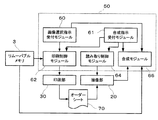
図4は、複合機1の論理的な構成を示す機能ブロック図である。
合成指示受付手段としての合成指示受付モジュール61は、合成指示を受け付ける画像処理プログラムの構成部品である。合成指示とは、手書き文字等を書き込むためのオーダーシートを印刷し、オーダーシートを読み取り、手書き文字等を他の画像に合成する一連の処理をユーザが複合機1に要求する指示である。
FIG. 4 is a functional block diagram showing a logical configuration of the multifunction machine 1.
The combination instruction receiving module 61 as a combination instruction receiving unit is a component part of an image processing program that receives a combination instruction. The composition instruction is an instruction for the user to request the multifunction device 1 to perform a series of processes for printing an order sheet for writing handwritten characters and the like, reading the order sheet, and compositing the handwritten characters and the like with another image.

画像選択指示受付手段としての画像選択指示受付モジュール60は、アクセス可能な画像ファイルから任意の画像ファイルを選択する指示(画像選択指示)を受け付けるプログラムの構成部品である。アクセス可能な画像ファイルとは、具体的には例えばリムーバブルメモリ3の所定フォルダに保存されている画像ファイルである。尚、画像選択指示受付モジュール60は、内部メモリであるROM52及びRAM53や、複合機1に接続されるディジタルカメラ、カメラ機能付き携帯電話等の携帯用電子機器のメモリや、複合機1に接続されるPCのハードディスク装置や、通信回線を介して複合機1に接続されているファイルサーバなどに保存されている画像データをユーザに選択させてもよい。   The image selection instruction receiving module 60 as an image selection instruction receiving means is a component part of a program that receives an instruction (image selection instruction) for selecting an arbitrary image file from accessible image files. Specifically, the accessible image file is, for example, an image file stored in a predetermined folder of the removable memory 3. The image selection instruction receiving module 60 is connected to the ROM 52 and RAM 53 which are internal memories, the memory of a portable electronic device such as a digital camera connected to the multifunction device 1, a mobile phone with a camera function, or the multifunction device 1. The user may select image data stored in a hard disk device of a PC or a file server connected to the multifunction device 1 via a communication line.

印刷制御手段としての印刷制御モジュール62は、オーダーシートを印刷するためのテンプレート(オーダーシートテンプレート)100(図5参照)をROM52から読み込み、オーダーシートテンプレート113に基づいてオーダーシートを印刷部30に印刷させる画像処理プログラムの構成部品である。   A print control module 62 serving as a print control unit reads a template (order sheet template) 100 (see FIG. 5) for printing an order sheet from the ROM 52, and prints the order sheet on the printing unit 30 based on the order sheet template 113. This is a component part of the image processing program to be executed.

図5に示すオーダーシートテンプレート113は、基準マーク82、107、検証マーク81及び領域枠110を用紙に印刷するためのオブジェクト情報及びレイアウト情報で構成される。枠112はオーダーシートテンプレート113が定義している印刷用紙サイズを意味している。オーダーシートテンプレート113が定義する領域表記としての領域枠110は、オーダーシート70(図6参照)の紙面上の自由描画領域72の外縁を示す矩形の枠である。自由描画領域72は、合成画像を印刷するための印刷用紙とは異なるアスペクト比の矩形枠でもよいし、円形枠などの矩形以外の枠でもよい。また領域表記は、例えば自由描画領域72の四隅を示す4つのマーク(十字形、L字形等)であってもよい。オーダーシートテンプレート113が定義する基準マーク82、107は、オーダーシート70を読み取る際に自由描画領域72及び検証マーク81の位置を特定するためのマークである。オーダーシートテンプレート113が定義する枠108は、検証マーク81が割り付けられる領域である。検証マーク81は請求項に記載の識別表記に相当し、後述する合成テンプレートを特定可能な情報を担持している。つまり、検証マーク81のパターンは、合成テンプレートに応じて決まっている。尚、複合機1が検証マーク81に基づいて選択可能な合成テンプレートは1つであってもよいし、複数であってもよい。すなわち、少なくとも、手書き文字などを記録できるオーダーシートであるか否かだけが検証マーク81に基づいて判定可能であればよい。検証マーク81からは、それぞれが異なる合成テンプレートに対応し手書き文字などを記録できる複数種類のオーダーシートのうちのいずれであるかまでは判定不能でもよい。また、検証マーク81は、合成テンプレートに対応していると同時に、当然に、オーダーシートテンプレート113にも対応している。合成テンプレートが定義する自由描画領域72の画像を割り付ける枠128(図7参照)とオーダーシートテンプレート113が定義する領域枠110とが対応しているからである。すなわち、検証マーク81はオーダーシート自体を識別可能な情報を担持している。また、検証マーク81は、オーダーシート70を印刷する処理の実行中に複合機1に接続されているリムーバブルメモリ3と、合成画像を印刷する処理の実行中に複合機1に接続されているリムーバブルメモリ3との同一性を検証するためのマークでもある。具体的には例えば、検証マーク81はリムーバブルメモリ3の所定のフォルダに格納された所定のフォーマットの全ての画像ファイルのファイル名、ファイル数等に基づいて算出されるチェックサムを特定可能な情報も担持している。   The order sheet template 113 shown in FIG. 5 includes object information and layout information for printing the reference marks 82 and 107, the verification mark 81, and the area frame 110 on a sheet. A frame 112 means a printing paper size defined by the order sheet template 113. The area frame 110 as the area notation defined by the order sheet template 113 is a rectangular frame indicating the outer edge of the free drawing area 72 on the paper surface of the order sheet 70 (see FIG. 6). The free drawing area 72 may be a rectangular frame having an aspect ratio different from that of printing paper for printing a composite image, or may be a non-rectangular frame such as a circular frame. The area notation may be, for example, four marks (cross shape, L shape, etc.) indicating the four corners of the free drawing area 72. The reference marks 82 and 107 defined by the order sheet template 113 are marks for specifying the positions of the free drawing area 72 and the verification mark 81 when the order sheet 70 is read. A frame 108 defined by the order sheet template 113 is an area to which the verification mark 81 is assigned. The verification mark 81 corresponds to the identification notation described in the claims, and carries information that can specify a composite template to be described later. That is, the pattern of the verification mark 81 is determined according to the composite template. Note that the composite machine 1 may select one composite template based on the verification mark 81 or a plurality of composite templates. In other words, it is sufficient that at least whether or not the order sheet can record handwritten characters can be determined based on the verification mark 81. From the verification mark 81, it may not be possible to determine whether the verification mark 81 is one of a plurality of types of order sheets corresponding to different composite templates and capable of recording handwritten characters. Further, the verification mark 81 corresponds to the composite template and, at the same time, naturally corresponds to the order sheet template 113. This is because the frame 128 (see FIG. 7) for assigning the image of the free drawing area 72 defined by the composite template and the area frame 110 defined by the order sheet template 113 correspond to each other. That is, the verification mark 81 carries information capable of identifying the order sheet itself. The verification mark 81 includes a removable memory 3 connected to the multifunction device 1 during execution of the process of printing the order sheet 70 and a removable memory 3 connected to the multifunction device 1 during execution of the process of printing a composite image. It is also a mark for verifying the identity with the memory 3. Specifically, for example, the verification mark 81 includes information that can specify a checksum calculated based on the file name, the number of files, and the like of all image files of a predetermined format stored in a predetermined folder of the removable memory 3. Carrying.

読み取り制御手段としての読取制御モジュール64は、画像処理プログラムの構成部品であって次の機能を有する。第一に、原稿台の全面(プレスキャン領域)を撮像部20に低解像度で読み取らせてプレスキャン画像を取得する。第二に、プレスキャン画像に基づいて検証マーク81を認識する。第三に、検証マーク81の認識結果に基づいてオーダーシート70の自由描画領域72を特定する。第四に、自由描画領域72を撮像部20に高解像度で読み取らせる。   The reading control module 64 as reading control means is a component of the image processing program and has the following functions. First, the prescan image is acquired by causing the imaging unit 20 to read the entire surface (prescan area) of the document table at a low resolution. Second, the verification mark 81 is recognized based on the pre-scan image. Third, the free drawing area 72 of the order sheet 70 is specified based on the recognition result of the verification mark 81. Fourth, the free drawing area 72 is read by the imaging unit 20 with high resolution.

合成手段及び領域抽出手段としての合成モジュール66は、撮像部20が読み取った自由描画領域72の画像を取得し、自由描画領域72の画像と他の画像とを合成する画像処理プログラムの構成部品である。具体的には例えば、合成モジュール66は、自由描画領域72の画像から手書き文字等の対象物116(図6参照)の領域を抽出し、後述する合成テンプレートに基づいて対象物116の画像をユーザが選択する写真画像に合成する。
以上説明した合成指示受付モジュール61、印刷制御モジュール62、読取制御モジュール64及び合成モジュール66が実行されることによって実現される制御部50の機能は、コンピュータプログラムの実行を伴わないASIC(Application Specific Integrated Circuit)等の専用ハードウェアによって実現することもできる。
The compositing module 66 serving as a compositing unit and an area extracting unit is a component of an image processing program that acquires an image of the free drawing area 72 read by the imaging unit 20 and combines the image of the free drawing area 72 with another image. is there. Specifically, for example, the compositing module 66 extracts a region of the object 116 (see FIG. 6) such as handwritten characters from the image of the free drawing region 72, and the user 116 converts the image of the target object 116 based on a composition template described later. Is combined with the selected photographic image.
The functions of the control unit 50 realized by executing the synthesis instruction receiving module 61, the print control module 62, the reading control module 64, and the synthesis module 66 described above are ASIC (Application Specific Integrated) that does not involve execution of a computer program. It can also be realized by dedicated hardware such as Circuit).

図7は合成テンプレートを説明するための模式図である。
合成テンプレート120は、用紙134に合成画像132を印刷するために必要なレイアウト情報で構成される。枠131は、合成テンプレート120が定義する印刷用紙サイズを表している。合成テンプレート120が定義する枠128は、自由描画領域72の画像122と他の画像126が割り付けられる領域である。図に示した例では、自由描画領域72の画像122と他の画像126が割り付けられる領域が一致しているが、勿論それぞれの画像を異なる枠に割り付けてもよい。合成テンプレート120が定義する枠128とオーダーシートテンプレート113が定義する領域枠110とは互いのアスペクト比が一致している。アルファチャンネル124は、自由描画領域72の画像122のレイヤの透過率を画素毎に定義する情報である。合成モジュール66が自由描画領域72の画像122に対する領域分割処理によって手書き文字等の対象物116の領域130を特定し、対象物116の領域130の透過率を不透明に設定し、その他の領域を透明に設定する処理によって、アルファチャンネル124は生成される。自由描画領域72の画像122と他の画像126とを画素毎にアルファチャンネル124で重み付けして加算することにより、合成画像132が生成される。
FIG. 7 is a schematic diagram for explaining a composite template.
The composite template 120 is composed of layout information necessary for printing the composite image 132 on the paper 134. A frame 131 represents the print paper size defined by the composite template 120. A frame 128 defined by the composite template 120 is an area to which the image 122 of the free drawing area 72 and another image 126 are allocated. In the example shown in the figure, the area 122 to which the image 122 of the free drawing area 72 and the other image 126 are allocated are the same, but each image may of course be allocated to a different frame. The aspect ratio of the frame 128 defined by the composite template 120 and the area frame 110 defined by the order sheet template 113 are the same. The alpha channel 124 is information that defines the transmittance of the layer of the image 122 in the free rendering area 72 for each pixel. The compositing module 66 specifies the region 130 of the object 116 such as handwritten characters by region dividing processing on the image 122 of the free drawing region 72, sets the transmittance of the region 130 of the object 116 to opaque, and makes the other regions transparent. The alpha channel 124 is generated by the process of setting to. The composite image 132 is generated by weighting and adding the image 122 of the free rendering area 72 and the other image 126 with the alpha channel 124 for each pixel.

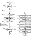
図8は、本発明の第一実施例による画像処理方法を示すフローチャートである。図8に示す処理は、制御部50が上述の画像処理プログラムを実行することによって実行される。
はじめに、制御部50は合成指示を受け付ける(ステップS100)。具体的には例えば、合成指示受付モジュール61は、図9に示すメニュー画面1000をLCD14に表示させ、その後に十字ボタン12の操作によりユーザが「手書き文字合成印刷」を選択し決定ボタン10を押すことによって操作部42から出力される信号を合成指示として受け付ける。図面では、LCD14に表示されている項目のうち十字ボタン12の操作により選択されている項目にハッチングを記している。
FIG. 8 is a flowchart showing an image processing method according to the first embodiment of the present invention. The process shown in FIG. 8 is executed by the control unit 50 executing the above-described image processing program.
First, the control unit 50 receives a composition instruction (step S100). Specifically, for example, the composition instruction receiving module 61 displays the menu screen 1000 shown in FIG. 9 on the LCD 14, and then the user selects “handwritten character composition printing” by operating the cross button 12 and presses the decision button 10. Thus, a signal output from the operation unit 42 is accepted as a synthesis instruction. In the drawing, the items selected by operating the cross button 12 among the items displayed on the LCD 14 are hatched.

制御部50は、合成指示を受け付けると、オーダーシートテンプレートを設定する(ステップS103)。具体的には、合成指示受付モジュール61は、ROM52からオーダーシートテンプレートをRAM53に読み込む。この処理により、合成指示に応じたオーダーシート70の自由描画領域72が設定される。尚、制御部50は、ステップS100で互いに異なるオーダーシートテンプレートに対応する合成指示を択一的に受け付け、受け付けた合成指示に応じたオーダーシートテンプレートを設定してもよい。   When the control unit 50 receives the compositing instruction, the control unit 50 sets an order sheet template (step S103). Specifically, the composition instruction receiving module 61 reads the order sheet template from the ROM 52 into the RAM 53. By this processing, a free drawing area 72 of the order sheet 70 corresponding to the compositing instruction is set. Note that the control unit 50 may alternatively receive a combining instruction corresponding to different order sheet templates in step S100 and set an order sheet template corresponding to the received combining instruction.

ステップS106では、複合機1はオーダーシート70を印刷する。具体的には、印刷制御モジュール62は、RAM53に読み込まれているオーダーシートテンプレートに基づいて、基準マーク82、107、検証マーク81及び領域枠110が割り付けられたページのデータを生成する。このとき印刷制御モジュール62は、合成指示に応じた合成テンプレートを特定可能な情報と、リムーバブルメモリ3の所定のディレクトリに格納された画像ファイル群に対応したチェックサムを特定可能な情報とを担持したパターンの検証マーク81をROM53から読み込んで枠108(図5参照)に割り付ける。チェックサムは、リムーバブルメモリ3の所定のディレクトリに格納された画像ファイル群に基づいて算出される。尚、合成テンプレートは合成指示に応じて決まるものであるから、検証マーク81のパターンは、合成指示に応じて決まるともいえる。次に印刷制御モジュール62は、基準マーク82、107、検証マーク81及び領域枠110が割り付けられたページのデータに二値化処理、インタレース処理等を施して印刷データを生成する。次に印刷制御モジュール62は、印刷部30に印刷データを出力し、オーダーシート70を印刷部30に印刷させる。また、印刷部30がオーダーシート70の印刷を完了するまでの期間、印刷制御モジュール62はLCD14に図9に示す画面1040を表示してもよい。   In step S <b> 106, the multifunction machine 1 prints the order sheet 70. Specifically, the print control module 62 generates data of pages to which the reference marks 82 and 107, the verification mark 81, and the area frame 110 are allocated based on the order sheet template read into the RAM 53. At this time, the print control module 62 carries information that can specify a composite template according to the composite instruction and information that can specify a checksum corresponding to a group of image files stored in a predetermined directory of the removable memory 3. The pattern verification mark 81 is read from the ROM 53 and assigned to the frame 108 (see FIG. 5). The checksum is calculated based on a group of image files stored in a predetermined directory of the removable memory 3. Since the synthesis template is determined according to the synthesis instruction, it can be said that the pattern of the verification mark 81 is determined according to the synthesis instruction. Next, the print control module 62 generates print data by performing binarization processing, interlace processing, and the like on the data of the page to which the reference marks 82 and 107, the verification mark 81, and the area frame 110 are assigned. Next, the print control module 62 outputs print data to the printing unit 30 and causes the printing unit 30 to print the order sheet 70. Further, the printing control module 62 may display the screen 1040 shown in FIG. 9 on the LCD 14 until the printing unit 30 completes the printing of the order sheet 70.

ユーザは、ステップS106で印刷されたオーダーシート70の自由描画領域72に図6に示すように手書き文字等の対象物116を記録する。自由描画領域72の外縁は領域枠110によって明示されている。自由描画領域72には、手書き文字の他、雑誌の切り抜きを貼り付けたり、文字や画像を印刷したりすることができる。
ステップS108では、制御部50は合成開始指示を受け付ける。具体的には例えば、合成指示受付モジュール61は、図9に示すメニュー画面1060をLCD14に表示させ、その後にユーザが決定ボタン10を押すことによって操作部42から出力される信号を合成開始指示として受け付ける。尚、合成開始指示を受け付けた後、制御部50はLCD14に図9に示す画面1080を表示して進捗状況をユーザに案内してもよい。
The user records an object 116 such as a handwritten character in the free drawing area 72 of the order sheet 70 printed in step S106 as shown in FIG. The outer edge of the free drawing area 72 is clearly indicated by the area frame 110. In the free drawing area 72, in addition to handwritten characters, magazine clippings can be pasted, and characters and images can be printed.
In step S108, the control unit 50 receives a synthesis start instruction. Specifically, for example, the composition instruction receiving module 61 displays a menu screen 1060 shown in FIG. 9 on the LCD 14 and then uses the signal output from the operation unit 42 when the user presses the enter button 10 as a composition start instruction. Accept. Note that after receiving the synthesis start instruction, the control unit 50 may display a screen 1080 shown in FIG.

ステップS109では、複合機1はプレスキャン領域を読み取る。具体的には読取制御モジュール64は、プレスキャン領域を撮像部20に読み取らせてプレスキャン画像を取得する。
ステップS110では、制御部50はオーダーシート70の自由描画領域72を特定する。具体的には読取制御モジュール64は、パターンマッチング等によってプレスキャン画像内で基準マーク82、107の位置を特定する。次に読取制御モジュール64は、基準マーク82、107の位置に基づいて検証マーク81の範囲を特定し、プレスキャン画像によって表されている検証マーク81を認識することにより、オーダーシート70を認識する。すなわち読取制御モジュール64は、オーダーシート70に応じて決まっている自由描画領域72の範囲を、検証マーク81を読み取った画像に基づいて特定する。このとき、検証マーク81に対応するオーダーシートテンプレート113で定義されている基準マーク82、107及び領域枠110の相対的な位置関係に応じた自由描画領域72の範囲が特定される。
In step S109, the multifunction device 1 reads the pre-scan area. Specifically, the reading control module 64 causes the imaging unit 20 to read the prescan area and obtain a prescan image.
In step S <b> 110, the control unit 50 specifies the free drawing area 72 of the order sheet 70. Specifically, the reading control module 64 specifies the positions of the reference marks 82 and 107 in the pre-scan image by pattern matching or the like. Next, the reading control module 64 identifies the range of the verification mark 81 based on the positions of the reference marks 82 and 107, and recognizes the verification mark 81 represented by the pre-scan image, thereby recognizing the order sheet 70. . That is, the reading control module 64 specifies the range of the free drawing area 72 determined according to the order sheet 70 based on the image obtained by reading the verification mark 81. At this time, the range of the free drawing area 72 corresponding to the relative positional relationship between the reference marks 82 and 107 and the area frame 110 defined in the order sheet template 113 corresponding to the verification mark 81 is specified.

またステップS110では、検証マーク81に対応するチェックサムと、リムーバブルメモリ3の所定のフォルダに格納された所定のフォーマットの画像ファイルに基づいて算出するチェックサムとの同一性を検証する。その結果、2つのチェックサムが一致していなければ制御部50はエラー処理を実施する。尚、このようなエラー判定及びエラー処理は勿論省略してもよい。
ステップS111では、制御部50は検証マーク81に対応する合成テンプレートを設定する。具体的には、合成モジュール66は、検証マーク81に対応する合成テンプレートをROM52からRAM53に読み込む。この処理により、自由描画領域72の画像122及び他の画像126について、合成指示に応じた配置、レイヤの上下関係、各レイヤの透過率、印刷用紙サイズ等が設定される。
In step S110, the identity of the checksum corresponding to the verification mark 81 and the checksum calculated based on the image file of a predetermined format stored in a predetermined folder of the removable memory 3 is verified. As a result, if the two checksums do not match, the control unit 50 performs error processing. Of course, such error determination and error processing may be omitted.
In step S <b> 111, the control unit 50 sets a composite template corresponding to the verification mark 81. Specifically, the synthesis module 66 reads a synthesis template corresponding to the verification mark 81 from the ROM 52 into the RAM 53. With this process, the arrangement according to the compositing instruction, the layer vertical relationship, the transmittance of each layer, the printing paper size, and the like are set for the image 122 and the other image 126 in the free drawing area 72.

ステップS112では、複合機1は自由描画領域72を高解像度で読み取る。具体的には読取制御モジュール64は、撮像部20に、自由描画領域72をプレスキャン時よりも高解像度で読み取らせ自由描画領域72の画像をRAM53に格納させる。
ステップS114では、制御部50は、自由描画領域72の画像122(図7参照)から自由描画領域72に記録された対象物116に対応する領域130を抽出する。具体的には、合成モジュール66は、自由描画領域72の画像122に対して所定のしきい値を用いた領域分割処理を施して対象物116に対応する領域130を特定する。尚、合成モジュール66は、プレスキャン画像を用いて対象物116に対応する領域を特定してもよい。次に合成モジュール66は、対象物116に対応する領域130を不透明に、その他の領域を透明に設定したアルファチャンネル124を生成する。
In step S112, the multi function device 1 reads the free rendering area 72 with high resolution. Specifically, the reading control module 64 causes the imaging unit 20 to read the free drawing area 72 at a higher resolution than during pre-scanning and store the image of the free drawing area 72 in the RAM 53.
In step S <b> 114, the control unit 50 extracts an area 130 corresponding to the object 116 recorded in the free drawing area 72 from the image 122 (see FIG. 7) of the free drawing area 72. Specifically, the composition module 66 performs region division processing using a predetermined threshold on the image 122 of the free drawing region 72 and specifies the region 130 corresponding to the object 116. Note that the synthesis module 66 may specify a region corresponding to the object 116 using the pre-scan image. Next, the composition module 66 generates an alpha channel 124 in which the region 130 corresponding to the object 116 is set to be opaque and the other regions are set to be transparent.

ステップS104では、複合機1はユーザがアクセス可能な画像ファイルから任意の画像ファイルを選択する指示を受け付ける。具体的には例えば、画像選択指示受付モジュール60は、図9に示す画像選択画面1020をLCD14に表示させ、その後にユーザが十字ボタン12及び決定ボタン10を押すことによって操作部42から出力される信号に応じて、リムーバブルメモリ3の所定のフォルダに格納されている所定のフォーマットの画像ファイルを選択する。尚、このステップS104の処理は、図10に示すようにオーダーシート70の印刷前に行ってもよい。   In step S104, the multifunction device 1 receives an instruction to select an arbitrary image file from image files accessible by the user. Specifically, for example, the image selection instruction receiving module 60 displays the image selection screen 1020 shown in FIG. 9 on the LCD 14, and then is output from the operation unit 42 when the user presses the cross button 12 and the determination button 10. In accordance with the signal, an image file of a predetermined format stored in a predetermined folder of the removable memory 3 is selected. Note that the processing in step S104 may be performed before the order sheet 70 is printed as shown in FIG.

ステップS116では、制御部50は、自由描画領域72の画像122(図7参照)と他の画像126とを合成する。具体的には、合成モジュール66は、合成テンプレート120に基づいて、自由描画領域72の画像122と、ステップS104で選択された画像ファイルが表す画像126とを画素毎にアルファチャンネル124で重み付けして加算し、その結果得られる合成画像132を枠128に割り付ける。このとき用いられる合成テンプレート120は、検証マーク81を認識した結果に応じて制御部50がROM52からRAM53に読み込んだものである(ステップS110及びステップS111参照)。自由描画領域72の画像122と他の画像126との合成は検証マーク81に応じて設定された合成テンプレート120に基づいて行われる。すなわち、制御部50は自由描画領域72の画像122と他の画像126とを検証マーク81に応じて合成する。   In step S <b> 116, the control unit 50 combines the image 122 (see FIG. 7) of the free drawing area 72 with another image 126. Specifically, the composition module 66 weights the image 122 of the free rendering area 72 and the image 126 represented by the image file selected in step S104 with an alpha channel 124 for each pixel based on the composition template 120. Addition is performed, and the resultant composite image 132 is assigned to the frame 128. The composite template 120 used at this time is the one read by the control unit 50 from the ROM 52 into the RAM 53 according to the result of recognizing the verification mark 81 (see step S110 and step S111). The composition of the image 122 in the free drawing area 72 and the other image 126 is performed based on the composition template 120 set according to the verification mark 81. That is, the control unit 50 combines the image 122 of the free drawing area 72 and another image 126 according to the verification mark 81.

ステップS118では、複合機1は合成画像を印刷する。具体的には、制御部50は合成テンプレート120に基づいて合成画像132が枠128に割り付けられたページのデータを生成し、そのデータに二値化処理、インタレース処理等を施して印刷データを生成し、印刷部30に印刷データを出力することによって、合成画像132を用紙134に印刷させる。   In step S118, the multifunction device 1 prints the composite image. Specifically, the control unit 50 generates data of a page in which the composite image 132 is allocated to the frame 128 based on the composite template 120, and performs binarization processing, interlace processing, and the like on the data to generate print data. The composite image 132 is printed on the paper 134 by generating and outputting the print data to the printing unit 30.

以上説明した本発明の第一実施例によると、ユーザは自由描画領域72に手書き文字等を書き込んだオーダーシート70を複合機1に読み取らせることによって、手書き文字等を他の画像に合成して得られる画像を複合機1に印刷させることができる。したがって、そのようにして得られる合成画像を印刷した印刷物を容易に大量に作成できる。また、光沢紙に印刷した写真画像に手書き文字をきれいに上書きすることは紙とインクの性質上困難であるが、上述の実施例によれば、ユーザはあたかも光沢紙に印刷した写真画像に手書き文字をきれいに上書きしたような印刷物を容易に作成することができる。
また、第一実施例では、合成印刷指示受け付け後に、合成テンプレートの設定と、画像の選択とが実行されるため、ステップS108以後の処理と、ステップS106以前の処理に連続性がなくてもよい。すなわち、ステップS106とステップS108の間に全く別の処理が行われてもよいし、複合機1の電源がオフになってもよい。
According to the first embodiment of the present invention described above, the user combines the handwritten characters with other images by causing the multifunction device 1 to read the order sheet 70 in which the handwritten characters are written in the free drawing area 72. The obtained image can be printed on the multifunction device 1. Therefore, it is possible to easily produce a large amount of printed matter on which the composite image obtained in this way is printed. In addition, it is difficult to cleanly overwrite handwritten characters on a photographic image printed on glossy paper due to the nature of paper and ink. However, according to the above-described embodiment, a user can write handwritten characters on a photographic image printed on glossy paper. It is possible to easily create a print that has been overwritten cleanly.
Further, in the first embodiment, after the composite print instruction is received, the composite template setting and the image selection are executed, so that the processing after step S108 and the processing before step S106 need not be continuous. . That is, completely different processing may be performed between step S106 and step S108, or the power of the multi-function device 1 may be turned off.

(第二実施例)
図11は、本発明の第二実施例による複合機1の機能ブロック図である。
印刷制御モジュール62は、上述のステップS106において、画像選択指示受付モジュール60によって選択された画像も図12に示すオーダーシートテンプレート113に基づいてオーダーシートに印刷する。図12に示すオーダーシートテンプレート113が定義する枠200は、画像選択指示受付モジュール60によって選択されたファイルを示す画像202が割り付けられる枠である。枠200の外側に用紙の外縁を示す枠が印刷されるようにオーダーシートテンプレート113を定義してもよい。そのようにすれば、ユーザは、選択したファイルの画像126(図7参照)が印刷用紙にどのように配置されるかを印刷前に確認できる。尚、印刷制御モジュール62は、ユーザによって選択された画像ファイルの画像126に基づいて生成した縮小画像を枠200に割り付けてもよい。また、選択された画像ファイルがExifファイルなどのサムネイルデータを格納している画像ファイルであれば、印刷制御モジュール62は、サムネイル画像を枠200に割り付けてもよい。
(Second embodiment)
FIG. 11 is a functional block diagram of the MFP 1 according to the second embodiment of the present invention.
In step S106 described above, the print control module 62 also prints the image selected by the image selection instruction receiving module 60 on the order sheet based on the order sheet template 113 shown in FIG. A frame 200 defined by the order sheet template 113 shown in FIG. 12 is a frame to which an image 202 indicating a file selected by the image selection instruction receiving module 60 is assigned. The order sheet template 113 may be defined such that a frame indicating the outer edge of the sheet is printed outside the frame 200. By doing so, the user can confirm how the image 126 (see FIG. 7) of the selected file is arranged on the printing paper before printing. Note that the print control module 62 may assign a reduced image generated based on the image 126 of the image file selected by the user to the frame 200. Further, if the selected image file is an image file storing thumbnail data such as an Exif file, the print control module 62 may assign the thumbnail image to the frame 200.

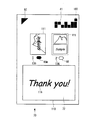
以上説明した本発明の第二実施例によると、複合機1は、図13に示すように、選択された画像データを示す画像202と自由描画領域72を示す領域枠110とを1枚のオーダーシート70に印刷する。そのためユーザは、選択した画像をオーダーシート70で確認しながら、選択した画像に合成するための手書き文字等の対象物116を自由描画領域72に記録することができる。つまりユーザは、合成結果を予想しながら自由描画領域72に対象物を記録することができる。   According to the second embodiment of the present invention described above, the multi-function device 1 orders the image 202 indicating the selected image data and the area frame 110 indicating the free rendering area 72 on one sheet as shown in FIG. Print on the sheet 70. Therefore, the user can record the object 116 such as a handwritten character to be combined with the selected image in the free drawing area 72 while confirming the selected image on the order sheet 70. That is, the user can record the object in the free drawing area 72 while predicting the synthesis result.

(第三実施例)
本発明の第二実施例による複合機1は、選択された画像ファイルが表す画像と手書き文字等の対象物の画像との合成結果の見本111をオーダーシート70に印刷する(図14参照)。
本発明の第三実施例では、合成指示受付モジュール61は、合成条件指示受付手段にも相当する。すなわち、合成指示受付モジュール61は、自由描画領域72に記録された対象物を表す画像122と他の画像126とを合成するための合成条件を選択する指示を受け付ける。合成条件とは、画像の配置、レイヤの上下関係、レイヤの透過率等であり、具体的には例えば合成テンプレートの内容である。合成指示受付モジュール61は、合成条件を選択する指示に応じて合成テンプレート及びオーダーシートテンプレートを設定する。
(Third embodiment)
The MFP 1 according to the second embodiment of the present invention prints on the order sheet 70 a sample 111 of the synthesis result of the image represented by the selected image file and the image of the object such as handwritten characters (see FIG. 14).
In the third embodiment of the present invention, the composition instruction receiving module 61 corresponds to a composition condition instruction receiving unit. That is, the compositing instruction reception module 61 receives an instruction to select a compositing condition for compositing the image 122 representing the object recorded in the free drawing area 72 and another image 126. The composition conditions are image arrangement, layer vertical relationship, layer transmittance, and the like, specifically, for example, the contents of a composition template. The composition instruction receiving module 61 sets a composition template and an order sheet template according to an instruction for selecting a composition condition.

図15は、オーダーシート70を印刷するためのオーダーシートテンプレート113を示す模式図である。図16は、図15に示すオーダーシートテンプレート113に対応する合成テンプレートを説明するための模式図である。すなわち、図15に示すオーダーシートテンプレート113と図16に示す合成テンプレート120とは、同一の合成条件を選択する指示に応じてROM52から読み込まれるテンプレートである。
オーダーシートテンプレート113は、手書き文字等が記録された自由描画領域72の見本を表す画像208が割り付けられる枠206を定義している。画像選択指示受付モジュール60によって選択されたファイルを示す画像202が割り付けられる枠200と、枠206とは、合成画像を印刷するための印刷用紙の外縁を表す矩形枠204の内側に定義される。矩形枠204のアスペクト比は合成画像を印刷するための印刷用紙のアスペクト比と一致している。尚、自由描画領域72の見本を表す画像208が割り付けられる枠206と、画像選択指示受付モジュール60によって選択されたファイルを示す画像202が割り付けられる枠200とが重なっている場合には、オーダーシートテンプレート113は2つの画像の透過率を設定するためのアルファチャンネルを定義する。
FIG. 15 is a schematic diagram showing an order sheet template 113 for printing the order sheet 70. FIG. 16 is a schematic diagram for explaining a composite template corresponding to the order sheet template 113 shown in FIG. That is, the order sheet template 113 shown in FIG. 15 and the composite template 120 shown in FIG. 16 are templates read from the ROM 52 in response to an instruction to select the same composite condition.
The order sheet template 113 defines a frame 206 to which an image 208 representing a sample of the free drawing area 72 in which handwritten characters are recorded is assigned. A frame 200 to which an image 202 indicating a file selected by the image selection instruction receiving module 60 is allocated, and a frame 206 are defined inside a rectangular frame 204 that represents the outer edge of a print sheet for printing a composite image. The aspect ratio of the rectangular frame 204 matches the aspect ratio of the printing paper for printing the composite image. When the frame 206 to which the image 208 representing the sample of the free drawing area 72 is allocated and the frame 200 to which the image 202 indicating the file selected by the image selection instruction receiving module 60 overlaps, the order sheet Template 113 defines an alpha channel for setting the transmittance of two images.

合成テンプレート120が定義する枠128aは、他の画像126が割り付けられる領域である。合成テンプレート120が定義する枠128bは、自由描画領域72の画像122が割り付けられる領域である。合成テンプレート120が定義する印刷用紙サイズに対応する枠131と、枠128aと、枠128bの相対的な大きさ及び相対的な位置の関係は、オーダーシートテンプレート113が定義する矩形枠204と、枠200と、枠206の相対的な大きさ及び相対的な位置の関係と等しい。すなわち、枠128a、128b、131を1つの図形とみなし、枠204、200、206を1つの図形とみなすと、それら2つの図形は互いに相似な関係にある。したがって、枠204、200、206に基づいてオーダーシート70に印刷される見本111(図14参照)によって、ユーザは合成結果を予測することができる。   A frame 128a defined by the composite template 120 is an area to which another image 126 is allocated. A frame 128b defined by the composite template 120 is an area to which the image 122 of the free drawing area 72 is allocated. The relationship between the relative size and relative position of the frame 131, the frame 128a, and the frame 128b corresponding to the print paper size defined by the composite template 120 is as follows: the rectangular frame 204 defined by the order sheet template 113; 200 is equal to the relationship between the relative size and relative position of the frame 206. That is, if the frames 128a, 128b, and 131 are regarded as one graphic and the frames 204, 200, and 206 are regarded as one graphic, the two graphics are similar to each other. Therefore, the user can predict the synthesis result by the sample 111 (see FIG. 14) printed on the order sheet 70 based on the frames 204, 200, and 206.

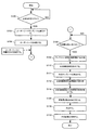
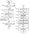
図17は、本発明の第三実施例による画像処理方法を示すフローチャートである。
ステップS101では、複合機1は、対象物の画像122と他の画像126とを合成するための互いに異なる合成条件の指示を受け付ける。具体的には、合成指示受付モジュール61は、図18に示すメニュー画面1100をLCD14に表示させ、その後に十字ボタン12の操作によりユーザがいずれかの合成条件を選択し決定ボタン10を押すことによって操作部42から出力される信号を合成条件指示として受け付ける。合成指示受付モジュール61は、合成結果を具体的に示す見本111を画面表示することにより選択可能な合成条件をユーザに案内してもよいし、「上下二段組」、「重ね合わせ」などの文字列を画面表示することにより選択可能な合成条件をユーザに案内してもよい。
FIG. 17 is a flowchart showing an image processing method according to the third embodiment of the present invention.
In step S <b> 101, the multifunction device 1 accepts instructions for different synthesis conditions for synthesizing the image 122 of the object and the other image 126. Specifically, the compositing instruction receiving module 61 displays the menu screen 1100 shown in FIG. 18 on the LCD 14, and then the user selects any compositing condition by operating the cross button 12 and presses the decision button 10. A signal output from the operation unit 42 is accepted as a synthesis condition instruction. The composition instruction receiving module 61 may guide the user to select a composition condition by displaying a sample 111 specifically indicating the composition result on the screen, or may include “upper and lower two columns”, “superposition”, and the like. The user may be guided to selectable synthesis conditions by displaying a character string on the screen.

ステップS102では、合成指示受付モジュール61は、ステップS101で受け付けた合成条件指示に応じたオーダーシートテンプレート113及び合成テンプレート120をROM52からRAM53に読み込む。この処理により、合成条件指示に応じたオーダーシート70の自由描画領域72が設定され、自由描画領域72の画像122及び他の画像126については、合成条件指示に応じた配置、レイヤの上下関係、各レイヤの透過率、印刷用紙サイズ等が設定される。   In step S102, the composition instruction receiving module 61 reads the order sheet template 113 and the composition template 120 corresponding to the composition condition instruction received in step S101 from the ROM 52 into the RAM 53. By this processing, the free drawing area 72 of the order sheet 70 corresponding to the compositing condition instruction is set, and for the image 122 and the other image 126 of the free drawing area 72, the arrangement according to the compositing condition instruction, the layer vertical relationship, The transmittance of each layer, the print paper size, etc. are set.

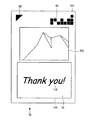
以上説明した本発明の第三実施例によると、オーダーシート70には選択された画像ファイルが表す画像と手書き文字等の対象物との合成結果の見本111が印刷されるため、ユーザは合成結果を具体的に想像しながら自由描画領域72に対象物を記録することができる。   According to the third embodiment of the present invention described above, the order sheet 70 is printed with the sample 111 of the combination result of the image represented by the selected image file and the target object such as handwritten characters. The object can be recorded in the free drawing area 72 while specifically imagining.

(第四実施例)
図19は、本発明の第四実施例による複合機1によって印刷されるオーダーシート70を示す模式図である。本発明の第四実施例による複合機1では、オーダーシート70に複数の見本111を印刷し、各見本111に付された識別子136を介して合成条件指示を受け付ける。オーダーシート70を印刷するためのテンプレートは、見本111を印刷するための定義情報が複数になる点を除いては第三実施例と実質的に同一であるため、説明を省略する。
(Fourth embodiment)
FIG. 19 is a schematic diagram showing an order sheet 70 printed by the multifunction machine 1 according to the fourth embodiment of the present invention. In the multifunction machine 1 according to the fourth embodiment of the present invention, a plurality of samples 111 are printed on the order sheet 70, and a synthesis condition instruction is received via an identifier 136 attached to each sample 111. The template for printing the order sheet 70 is substantially the same as that of the third embodiment except that there are a plurality of pieces of definition information for printing the sample 111, and the description thereof will be omitted.

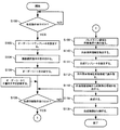
図20は、本発明の第四実施例による画像処理方法を示すフローチャートである。
複合機1は、ステップS108で合成印刷指示を受け付けた後にステップS101を実施して合成条件指示を受け付ける。具体的には、合成指示受付モジュール61は、図21に示すメニュー画面1110をLCD14に表示させる。メニュー画面1110では、十字ボタン12及び決定ボタン10を押すことによって、オーダーシート70の各見本111に付された識別子136のいずれかを選択可能である。合成指示受付モジュール61は、ユーザが十字ボタン12及び決定ボタン10を押すことによって操作部42から出力される信号に応じて、いずれの合成条件条件指示を受け付ける。
ステップS111では、制御部50はステップS110で受け付けられた合成条件指示に応じて合成テンプレートを設定する。具体的には、合成モジュール66は、ステップS110でユーザが選択した識別子に応じた合成テンプレートをROM52からRAM53に読み込む。
FIG. 20 is a flowchart showing an image processing method according to the fourth embodiment of the present invention.
After receiving the composite print instruction in step S108, the multifunction machine 1 executes step S101 and receives the composite condition instruction. Specifically, the composition instruction receiving module 61 displays a menu screen 1110 shown in FIG. 21 on the LCD 14. On the menu screen 1110, one of the identifiers 136 attached to each sample 111 of the order sheet 70 can be selected by pressing the cross button 12 and the determination button 10. The combination instruction receiving module 61 receives any combination condition instruction according to a signal output from the operation unit 42 when the user presses the cross button 12 and the determination button 10.
In step S111, the control unit 50 sets a synthesis template according to the synthesis condition instruction received in step S110. Specifically, the synthesis module 66 reads a synthesis template corresponding to the identifier selected by the user in step S110 from the ROM 52 into the RAM 53.

以上説明した本発明の第四実施例によると、ユーザが選択しうる合成条件に応じた複数の見本111がオーダーシート70に印刷される。そのためユーザは、LCD14の解像度が低く画面サイズが小さい場合であっても、選択可能な合成条件を具体的に認識することができる。   According to the fourth embodiment of the present invention described above, a plurality of samples 111 corresponding to the synthesis conditions that can be selected by the user are printed on the order sheet 70. Therefore, the user can specifically recognize selectable synthesis conditions even when the resolution of the LCD 14 is low and the screen size is small.

(第五実施例)
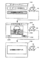
図1は、本発明の第五実施例による複合機1によって印刷されるオーダーシート70を示す模式図である。本発明の第五実施例による複合機1では、オーダーシート70に合成条件を選択するための複数のチェックボックス88を印刷し、チェックボックス88を塗りつぶした筆跡88mを光学的に認識することによって合成条件を設定する。オーダーシート70を印刷するためのテンプレートは、合成結果を表す複数の見本111のそれぞれの直下にチェックボックス88を配置している。見本111は請求項に記載の合成条件表記に相当する。ユーザは、いずれかのチェックボックス88を塗りつぶすことにより、そのチェックボックス88の真上に配置されている見本111に対応する合成条件を選択することができる。チェックボックス88を塗りつぶした筆跡88mが合成条件指示に相当する。
(Fifth embodiment)
FIG. 1 is a schematic diagram showing an order sheet 70 printed by the multifunction machine 1 according to the fifth embodiment of the present invention. In the multi function device 1 according to the fifth embodiment of the present invention, a plurality of check boxes 88 for selecting a synthesis condition are printed on the order sheet 70, and the handwriting 88m filled with the check boxes 88 is optically recognized to synthesize. Set conditions. In the template for printing the order sheet 70, a check box 88 is arranged immediately below each of the plurality of samples 111 representing the synthesis result. The sample 111 corresponds to the composition condition notation described in the claims. The user can select a synthesis condition corresponding to the sample 111 arranged immediately above the check box 88 by painting one of the check boxes 88. The handwriting 88m in which the check box 88 is filled corresponds to the synthesis condition instruction.

図22は、本発明の第五実施例による画像処理方法を示すフローチャートである。
ステップS111では、制御部50は塗りつぶされたチェックボックス88に対応する合成テンプレートを設定する。具体的には、合成条件認識手段としての合成モジュール66は、いずれのチェックボックス88が塗りつぶされているかをプレスキャン画像に基づいて判定し、塗りつぶされているチェックボックス88に対応する合成テンプレートをROM52からRAM53に読み込む。その結果、オーダーシート70に記録された合成条件指示に指示された見本111が表す合成条件が制御部50に認識される。
FIG. 22 is a flowchart showing an image processing method according to the fifth embodiment of the present invention.
In step S <b> 111, the control unit 50 sets a composite template corresponding to the filled check box 88. Specifically, the composition module 66 as the composition condition recognizing means determines which check box 88 is filled based on the pre-scanned image, and sets the composition template corresponding to the filled check box 88 to the ROM 52. To RAM 53. As a result, the control unit 50 recognizes the composition condition represented by the sample 111 instructed by the composition condition instruction recorded on the order sheet 70.

以上説明した本発明の第五実施例によると、ユーザは自由描画領域72に手書き文字等を記録する前後にチェックボックス88を塗りつぶすことにより、合成条件を指示できるため、合成条件を容易に設定することができる。   According to the fifth embodiment of the present invention described above, since the user can indicate the composition condition by filling the check box 88 before and after recording the handwritten character or the like in the free drawing area 72, the composition condition is easily set. be able to.

(第六実施例)
図23は、本発明の第六実施例による複合機1によって印刷されるオーダーシート70を示す模式図である。本発明の第六実施例による複合機1では、オーダーシート70に印刷条件を選択するためのチェックボックス91、76を印刷し、チェックボックス91、76を塗りつぶした筆跡91m、76mを光学的に認識することによって印刷条件を設定する。ユーザは、複数のチェックボックス91のいずれか1つを塗りつぶすことにより、複数種類の印刷用紙からいずれか1つを選択することができる。またユーザは、複数のチェックボックス76のいずれか1つを塗りつぶすことにより、印刷枚数を選択することができる。
本発明の第六実施例によると、ユーザは自由描画領域72に手書き文字等を記録する前後にチェックボックス91、76を塗りつぶすことにより、印刷条件を指示できるため、印刷条件を容易に設定することができる。
(Sixth embodiment)
FIG. 23 is a schematic diagram showing an order sheet 70 printed by the multifunction machine 1 according to the sixth embodiment of the present invention. In the multi function device 1 according to the sixth embodiment of the present invention, check boxes 91 and 76 for selecting printing conditions are printed on the order sheet 70, and handwriting 91m and 76m in which the check boxes 91 and 76 are filled are optically recognized. To set the printing conditions. The user can select any one of a plurality of types of printing paper by painting any one of the plurality of check boxes 91. Further, the user can select the number of prints by painting any one of the plurality of check boxes 76.
According to the sixth embodiment of the present invention, since the user can instruct the printing condition by filling the check boxes 91 and 76 before and after recording the handwritten character or the like in the free drawing area 72, the printing condition can be easily set. Can do.

(第七実施例)
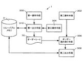
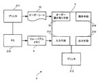
図24は、本発明の第七実施例による複合機1の機能ブロック図である。
第三操作手段304は、操作部42、合成指示受付モジュールを実行する制御部50等で構成され、後述する画像選択領域71で選択された画像と自由描画領域72を表す画像とのレイアウトを選択する所定のボタン操作を受け付ける。
第一操作手段300は、合成指示受付モジュールを実行する制御部50、操作部42等で構成され、所定のボタン操作をオーダーシート要求として受け付ける。
(Seventh embodiment)
FIG. 24 is a functional block diagram of the multifunction machine 1 according to the seventh embodiment of the present invention.
The third operation unit 304 includes the operation unit 42, the control unit 50 that executes the compositing instruction reception module, and the like, and selects a layout between an image selected in the image selection area 71 and an image representing the free drawing area 72 described later. A predetermined button operation is accepted.
The first operation unit 300 includes a control unit 50 that executes a synthesis instruction receiving module, an operation unit 42, and the like, and receives a predetermined button operation as an order sheet request.

第一出力手段310は、印刷制御モジュールを実行する制御部50、カード読み書き部41、印刷部30等で構成される。第一出力手段310は、第一操作手段300によりオーダーシート要求が受け付けられると、リムーバブルメモリ3に記憶された画像データとROM52に記憶されたテンプレートを読み込んで後述するオーダーシートを印刷する。   The first output unit 310 includes a control unit 50 that executes a print control module, a card read / write unit 41, a printing unit 30, and the like. When an order sheet request is received by the first operation means 300, the first output means 310 reads the image data stored in the removable memory 3 and the template stored in the ROM 52 and prints an order sheet described later.

第二操作手段302は、合成指示受付モジュールを実行する制御部50、操作部42等で構成され、所定のボタン操作を合成画像の印刷要求として受け付ける。
オーダー読み取り手段306は、読み取り制御モジュール及び画像選択指示認識モジュールを実行する制御部50、撮像部20等で構成され、第二操作手段302により合成画像の印刷要求が受け付けられると、オーダーシート70を読み取り、後述する検証マーク81、基準マーク82、塗りつぶされたチェックボックス74m、76m、79m、86m、及び87mを光学的に認識し、また自由描画領域72の画像を出力する。画像選択指示認識手段としての画像選択指示認識モジュールは、チェックボックス74を読み取った画像に基づいて、ユーザが選択した画像ファイルを認識する画像処理プログラムの構成部品である。
The second operation unit 302 includes a control unit 50 that executes a combination instruction reception module, an operation unit 42, and the like, and receives a predetermined button operation as a composite image print request.
The order reading unit 306 includes a control unit 50 that executes a reading control module and an image selection instruction recognition module, the imaging unit 20, and the like. When the second operation unit 302 receives a print request for a composite image, the order reading unit 306 receives the order sheet 70. Read, optically recognize verification marks 81, reference marks 82, and filled check boxes 74m, 76m, 79m, 86m, and 87m, which will be described later, and output an image of the free drawing area 72. The image selection instruction recognition module as an image selection instruction recognition unit is a component of an image processing program that recognizes an image file selected by the user based on an image obtained by reading the check box 74.

第二出力手段308は、合成モジュールを実行する制御部50、印刷部30等で構成され、画像選択領域71で選択された画像と自由描画領域72を表す画像との合成画像を印刷する。尚、後述するプレビューでは、第二出力手段308は、合成画像を印刷せずにLCD14に表示する。   The second output unit 308 includes a control unit 50 that executes a synthesis module, a printing unit 30, and the like, and prints a composite image of the image selected in the image selection area 71 and the image representing the free drawing area 72. In the preview described later, the second output unit 308 displays the composite image on the LCD 14 without printing.

図25は、図26に示すディレクトリ構造のリムーバブルメモリ3が接続された状態で複合機1によって印刷されるオーダーシート70の一例を示す模式図である。オーダーシート70のレイアウトはROM52に記憶されたオーダーシートテンプレートによって定義されている。図29は、必要事項がユーザによって記入されたオーダーシート70の一例を示す模式図である。オーダーシート70に表記される各要素の配置は、基準マーク82を基準として設定されている。   FIG. 25 is a schematic diagram showing an example of an order sheet 70 printed by the multifunction machine 1 in a state where the removable memory 3 having the directory structure shown in FIG. 26 is connected. The layout of the order sheet 70 is defined by an order sheet template stored in the ROM 52. FIG. 29 is a schematic diagram showing an example of an order sheet 70 in which necessary items are entered by the user. The arrangement of each element written on the order sheet 70 is set with reference to the reference mark 82.

基準マーク82は、オーダーシート70の上部左隅にレイアウトされている。オーダー読み取り手段306が基準マーク82の位置を認識することにより、オーダーシート70に表記されている各要素の位置を相対的に認識できる。
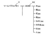
画像選択領域71には、リムーバブルメモリ3のDCIMフォルダ90に保存されている画像ファイル(例えば、木.jpg、顔.jpg、花.jpg、海.jpg、もみじ.jpg、日の出.jpg、山.jpg、人.jpg)に格納されているサムネイル画像73とチェックボックス74がレイアウトされている。チェックボックス74を塗りつぶすことにより、そのチェックボックス74mの直上にレイアウトされているサムネイル画像73m(例えば、日の出.jpgのサムネイル画像)に対応する画像ファイルの本画像を合成対象として選択できる。サムネイル画像73は請求項に記載の画像表記に相当する。チェックボックス74mを塗りつぶした筆跡が請求項に記載の画像選択指示に相当する。尚、リムーバブルメモリ3のDCIMフォルダ90に保存されている画像ファイルは、本画像で表記してもよいし、ファイル名や内部識別子を印刷して表記してもよい。
The reference mark 82 is laid out in the upper left corner of the order sheet 70. When the order reading unit 306 recognizes the position of the reference mark 82, the position of each element written on the order sheet 70 can be relatively recognized.
In the image selection area 71, image files (for example, tree.jpg, face.jpg, flower.jpg, sea.jpg, maple.jpg, sunrise.jpg, mountain.jpg) stored in the DCIM folder 90 of the removable memory 3 are displayed. jpg, person.jpg) are laid out and thumbnail images 73 and check boxes 74 are laid out. By painting the check box 74, the main image of the image file corresponding to the thumbnail image 73m (for example, the sunrise.jpg thumbnail image) laid out immediately above the check box 74m can be selected as a compositing target. The thumbnail image 73 corresponds to the image notation described in the claims. The handwriting that fills the check box 74m corresponds to the image selection instruction described in the claims. The image file stored in the DCIM folder 90 of the removable memory 3 may be expressed as a main image or may be expressed by printing a file name or an internal identifier.

自由描画領域72は、手書き文字(例えば、「賀正」)を描画したり、雑誌の切り抜きを貼付けたりするための空白領域であって矩形枠で囲まれている。自由描画領域72に手書きされる文字や図形の筆跡、自由描画領域72に貼り付けられる印刷物、自由描画領域に印刷される文字や図形が請求項に記載の対象物に相当する。   The free drawing area 72 is a blank area for drawing a handwritten character (for example, “Kagasho”) or pasting a magazine cutout, and is surrounded by a rectangular frame. Characters and figures handwritten in the free drawing area 72, printed matter pasted in the free drawing area 72, and characters and figures printed in the free drawing area correspond to the objects described in the claims.

印刷枚数を選択する領域75には、0〜99枚までの印刷枚数の各桁の数字に対応するチェックボックス76及びプレビューを選択するチェックボックス84がレイアウトされている。左の列にレイアウトされているチェックボックス76を塗りつぶすことにより印刷枚数の十の位の数字を選択し、右の列にレイアウトされているチェックボックス76を塗りつぶすことにより印刷枚数の一の位の数字を選択できる。   In the area 75 for selecting the number of printed sheets, a check box 76 corresponding to each digit of the number of printed sheets from 0 to 99 and a check box 84 for selecting a preview are laid out. The tens digit of the number of printed sheets is selected by filling the check box 76 laid out in the left column, and the first digit of the number of printed sheets is filled in by filling the check box 76 laid out in the right column. Can be selected.

レイアウト選択領域77には、レイアウトを模式的に示す画像78とチェックボックス79とがレイアウトされている。チェックボックス79を塗りつぶすことにより、そのチェックボックス79mの直上にレイアウトされている画像78mに対応するレイアウトを選択できる。チェックボックス79を塗りつぶした筆跡(79m)が請求項に記載の合成条件指示に相当する。   In the layout selection area 77, an image 78 and a check box 79 schematically showing the layout are laid out. By filling the check box 79, a layout corresponding to the image 78m laid out immediately above the check box 79m can be selected. The handwriting (79m) in which the check box 79 is filled corresponds to the composition condition instruction described in the claims.

重畳合成条件選択領域85には、チェックボックス86、チェックボックス87が表示されている。チェックボックス86を塗りつぶすことにより、画像選択領域71で選択された画像に手書き文字を重畳合成するとき白縁取りを施すか否かの境界処理条件を選択することができる。また、チェックボックス87を塗りつぶすことにより、手書き文字を表すレイヤの透明度(例えば、0%)を選択できる。尚、境界処理条件として白縁取りの幅を設定できてもよいし、重畳合成条件として他の透明度を選択できてもよい。   A check box 86 and a check box 87 are displayed in the superimposition synthesis condition selection area 85. By filling the check box 86, it is possible to select a boundary processing condition as to whether or not to perform white bordering when a handwritten character is superimposed and synthesized on the image selected in the image selection area 71. Further, by filling the check box 87, the transparency (for example, 0%) of the layer representing the handwritten character can be selected. Note that the width of the white border may be set as the boundary processing condition, or another transparency may be selected as the superposition synthesis condition.

図27は、本発明の第七実施例による複合機1で合成画像を印刷する処理を示すフローチャートである。図28は、LCD14の画面遷移を示す模式図である。
複合機1にリムーバブルメモリ3を接続し、メニュー画面100でユーザが十字ボタン12により「オーダーシートを印刷する」を選択して決定ボタン10を押すと、LCD14にはオーダーシート70のテンプレートを選択する画面102が表示される。画面102でユーザが十字ボタン12でテンプレート(例えば、年賀状)を選択して決定ボタン10を押すと、第一操作手段300がオーダーシート70の印刷要求を受け付ける。第一操作手段300がオーダーシート70の印刷要求を受け付けると、ステップS12に進む(ステップS10)。
FIG. 27 is a flowchart showing a process of printing a composite image by the multifunction machine 1 according to the seventh embodiment of the present invention. FIG. 28 is a schematic diagram showing screen transition of the LCD 14.
When the removable memory 3 is connected to the multifunction device 1 and the user selects “print order sheet” with the cross button 12 and presses the enter button 10 on the menu screen 100, the template of the order sheet 70 is selected on the LCD 14. A screen 102 is displayed. When the user selects a template (for example, a New Year's card) with the cross button 12 on the screen 102 and presses the enter button 10, the first operation unit 300 receives a print request for the order sheet 70. When the first operation means 300 accepts the print request for the order sheet 70, the process proceeds to step S12 (step S10).

ステップS12では、オーダーシート70の印刷中であることを示す画面104がLCD14に表示され、第一出力手段310がオーダーシート70を印刷する。
ステップS14において、ユーザは印刷されたオーダーシート70のチェックボックス74、76、79、86、87を、設定しようとする画像処理条件に応じて塗りつぶし、自由描画領域72に手書き文字を描画する(図29参照)。
In step S <b> 12, the screen 104 indicating that the order sheet 70 is being printed is displayed on the LCD 14, and the first output unit 310 prints the order sheet 70.
In step S14, the user fills the check boxes 74, 76, 79, 86, and 87 of the printed order sheet 70 according to the image processing conditions to be set, and draws handwritten characters in the free drawing area 72 (FIG. 29).

次に、ユーザがオーダーシート70を図示しない原稿台の所定の位置に置き、メニュー画面100で十字ボタン12により「合成画像を印刷する」を選択して決定ボタン10を押すと、第二操作手段302が合成画像の印刷要求を受け付ける。第二操作手段302が合成画像の印刷要求を受け付けるとステップS18に進む(ステップS16)。   Next, when the user places the order sheet 70 at a predetermined position on the document table (not shown), selects “print composite image” with the cross button 12 on the menu screen 100 and presses the enter button 10, the second operation means 302 accepts a composite image print request. When the second operation means 302 receives the composite image print request, the process proceeds to step S18 (step S16).

ステップS18では、合成画像の印刷中であることを示す画面106がLCD14に表示され、第二出力手段308が合成画像を印刷する。合成画像の印刷が完了すると、メニュー画面100がLCD14に表示される。
図30はオーダーシート70を印刷する処理(ステップS12)の詳細を示すフローチャートである。
In step S18, a screen 106 indicating that the composite image is being printed is displayed on the LCD 14, and the second output means 308 prints the composite image. When printing of the composite image is completed, the menu screen 100 is displayed on the LCD 14.
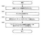
FIG. 30 is a flowchart showing details of the process of printing the order sheet 70 (step S12).

第一操作手段300によりオーダーシート70の印刷要求が受け付けられると、第一出力手段310は、リムーバブルメモリ3のDCIMフォルダ90に保存されている画像ファイルに識別子を付与する(ステップS200)。このとき、画像ファイルのファイル名のアスキーコード順に、各画像ファイルに識別子としての連続番号を付与する。   When the print request for the order sheet 70 is received by the first operation unit 300, the first output unit 310 gives an identifier to the image file stored in the DCIM folder 90 of the removable memory 3 (step S200). At this time, a serial number as an identifier is assigned to each image file in the ASCII code order of the file name of the image file.

次に、チェックサムを設定する(ステップS201)。チェックサムは、リムーバブルメモリ3のDCIMフォルダ90に保存されているデータの内容に応じて算出され、RAM53の所定の領域に保存される。
次に、ステップS10で選択されたテンプレートをROM52からRAM53に読み込み(ステップS202)、第一出力手段310は、当該テンプレートで定義されたレイアウト枠に画像ファイルのサムネイル画像及び検証マーク81を割り付けてオーダーシート70を印刷する(ステップS203)。
Next, a checksum is set (step S201). The checksum is calculated according to the content of data stored in the DCIM folder 90 of the removable memory 3 and stored in a predetermined area of the RAM 53.
Next, the template selected in step S10 is read from the ROM 52 into the RAM 53 (step S202), and the first output means 310 assigns the thumbnail image of the image file and the verification mark 81 to the layout frame defined by the template and orders them. The sheet 70 is printed (step S203).

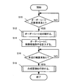
図31は合成画像を印刷する処理(ステップS18)の詳細を示すフローチャートである。
ステップS300では、オーダー読み取り手段306が低解像度のモノクロ2値画像としてオーダーシート70を読み取り、基準マーク82に基づいて検証マーク81とチェックボックス74、76、79、86、87との位置を画像上で特定した上で、検証マーク81と、塗りつぶされたチェックボックス(図1参照)74m、76m、79m、86m、及び87mによって選択された処理条件と、を光学的に認識する。
FIG. 31 is a flowchart showing details of the process (step S18) for printing a composite image.
In step S300, the order reading unit 306 reads the order sheet 70 as a low-resolution monochrome binary image, and the positions of the verification mark 81 and the check boxes 74, 76, 79, 86, 87 on the image based on the reference mark 82. Then, the verification mark 81 and the processing conditions selected by the filled check boxes (see FIG. 1) 74m, 76m, 79m, 86m, and 87m are optically recognized.

ステップS302では、ステップS300で認識された検証マーク81に対応するチェックサムとステップS201で設定したチェックサムとを比較し、オーダーシート70に表記されている画像ファイルとリムーバブルメモリ3に格納されている画像ファイルが一致しているか否かを判断する。一致していればステップS304に進み、一致していなければオーダーシート70に表記されている画像ファイルとリムーバブルメモリ3に格納されている画像ファイルが異なる旨を警告する画面をLCD14に表示する(ステップS306)。   In step S302, the checksum corresponding to the verification mark 81 recognized in step S300 is compared with the checksum set in step S201, and the image file written in the order sheet 70 is stored in the removable memory 3. It is determined whether the image files match. If they match, the process proceeds to step S304. If they do not match, a screen is displayed on the LCD 14 that warns that the image file written in the order sheet 70 is different from the image file stored in the removable memory 3 (step 14). S306).

ステップS304では、画像選択領域71で2つ以上の画像ファイルが選択されていないかを判別する。画像ファイルが1つだけ選択されていればステップS308に進み、2つ以上選択されていればその旨を警告する画面をLCD14に表示する(ステップS310)。
次に、ステップS300で認識された基準マーク82に基づいて自由描画領域72の範囲を認識する(ステップS308)。基準マーク82を利用して画像上で自由描画領域72の範囲を特定することにより、原稿台上で予め決められた位置にオーダーシート70が置かれていなくても自由描画領域72の位置を正確に特定することができる。
In step S304, it is determined whether or not two or more image files are selected in the image selection area 71. If only one image file has been selected, the process proceeds to step S308. If two or more image files have been selected, a screen for warning that effect is displayed on the LCD 14 (step S310).
Next, the range of the free drawing area 72 is recognized based on the reference mark 82 recognized in step S300 (step S308). By specifying the range of the free drawing area 72 on the image using the reference mark 82, the position of the free drawing area 72 can be accurately determined even when the order sheet 70 is not placed at a predetermined position on the document table. Can be specified.

次に、オーダー読み取り手段306が自由描画領域72とその近傍の余白領域83(図25参照)を高解像度で読み取る(ステップS312)。
次に、自由描画領域72を表す画像から手書き文字等の対象物の領域を抽出する(ステップS314)。尚、ステップS314を行わず、自由描画領域72を表す画像をそのまま画像選択領域71で選択された画像と合成すると、自由描画領域72の余白を含む全体を表す画像を画像選択領域71で選択された画像に合成した画像(図13(a)参照)を作成することができる。
Next, the order reading unit 306 reads the free drawing area 72 and the margin area 83 (see FIG. 25) in the vicinity thereof with high resolution (step S312).
Next, a region of an object such as a handwritten character is extracted from the image representing the free drawing region 72 (step S314). If the image representing the free drawing area 72 is directly combined with the image selected in the image selection area 71 without performing step S314, the image representing the entire area including the margin of the free drawing area 72 is selected in the image selection area 71. An image (see FIG. 13A) synthesized with the selected image can be created.

ステップS316では、ステップS314で抽出された領域の手書き文字等の対象物と画像選択領域71で選択された合成対象の画像とを、レイアウト選択領域77で選択されたレイアウトに応じて合成する。
次に、印刷枚数を選択する領域75で選択された印刷枚数だけ合成画像が印刷されるまで合成画像の印刷を第二出力手段308で繰り返す(ステップS318、320)。
In step S316, the object such as the handwritten character in the area extracted in step S314 and the image to be combined selected in the image selection area 71 are combined according to the layout selected in the layout selection area 77.
Next, the second output unit 308 repeats printing of the composite image until the composite image is printed by the number of prints selected in the area 75 for selecting the number of prints (steps S318 and 320).

図32は、自由描画領域72を表す画像から手書き文字の領域を抽出し、抽出した領域を画像選択領域71で選択された画像に重畳合成するための処理(ステップS314)の詳細を示すフローチャートである。
ステップS400では、オーダーシート70の地色が表れている余白領域83と手書き文字とを分けるしきい値を決定する。具体的にはまず始めに、余白領域83の輝度ヒストグラムを作成する。この輝度ヒストグラムでは、図33に示すように、オーダーシート70の地色に対応する輝度値に分布が集中する。そこで次に、自由描画領域72を表す画像から対象物の領域を抽出するためのしきい値を、その分布が集中する範囲の近傍に設定する。これにより、オーダーシート70に用いられた印刷用紙の地色に応じた適切な値に設定することができる。
FIG. 32 is a flowchart showing details of processing (step S314) for extracting a handwritten character region from an image representing the free drawing region 72 and superimposing the extracted region on the image selected in the image selection region 71. is there.
In step S400, a threshold value for separating the blank area 83 where the ground color of the order sheet 70 appears and the handwritten character is determined. Specifically, first, a luminance histogram of the margin area 83 is created. In this luminance histogram, as shown in FIG. 33, the distribution is concentrated on the luminance values corresponding to the ground color of the order sheet 70. Therefore, next, a threshold value for extracting the object region from the image representing the free drawing region 72 is set in the vicinity of the range where the distribution is concentrated. Thereby, it is possible to set an appropriate value according to the ground color of the printing paper used for the order sheet 70.

ステップS402では、特定したしきい値に基づいて、自由描画領域72を表す画像から手書き文字の領域を抽出し、当該領域のアルファチャンネルの値を重畳合成条件選択領域85のチェックボックス87で選択された透明度に設定し、それ以外の領域のアルファチャンネルの値を完全な透明に設定する。アルファチャンネルとは、画素毎に当該画像のレイヤの透明度を表すチャンネルである。   In step S402, based on the specified threshold value, an area of handwritten characters is extracted from the image representing the free drawing area 72, and the alpha channel value of the area is selected by the check box 87 of the superposition synthesis condition selection area 85. And set the alpha channel value for all other areas to be completely transparent. The alpha channel is a channel that represents the transparency of the layer of the image for each pixel.

ステップS403では、手書き文字として抽出された領域に含まれているノイズを除去する。具体的には、抽出された領域のうち所定数以下の画素数で構成される島状の領域の透明度を完全な透明に設定する。ここで、図34(b)は、アルファチャンネルにおいてノイズに相当する領域の透明度を変更しない場合、すなわちノイズの除去を行わない場合の重畳合成処理を示す模式図であり、図34(c)は、アルファチャンネルにおいてノイズに相当する領域の透明度を完全に透明にした場合、すなわちノイズの除去を行った場合の重畳合成処理を示す模式図である。   In step S403, noise included in the region extracted as handwritten characters is removed. Specifically, the transparency of the island-shaped region composed of a predetermined number or less of the extracted regions is set to be completely transparent. Here, FIG. 34 (b) is a schematic diagram showing the superimposition synthesis process when the transparency of the area corresponding to noise in the alpha channel is not changed, that is, when noise removal is not performed. FIG. 10 is a schematic diagram showing a superposition and synthesis process when the transparency of a region corresponding to noise in the alpha channel is made completely transparent, that is, when noise is removed.

次に、重畳合成条件として白縁取りが選択されていれば、アルファチャンネルの不透明領域を膨張させる(ステップS404)。この結果、ステップS316では、手書き文字の周辺のオーダーシート70の地色が画像選択領域71で選択された画像の上に重畳合成されるため、手書き文字等に縁取りをして合成画像を形成することができる(図34(d)参照)。以上ステップS314の処理を詳細に説明した。   Next, if white bordering is selected as the superposition synthesis condition, the opaque region of the alpha channel is expanded (step S404). As a result, in step S316, the ground color of the order sheet 70 around the handwritten character is superimposed and synthesized on the image selected in the image selection area 71, so that the handwritten character is trimmed to form a synthesized image. (See FIG. 34 (d)). The processing in step S314 has been described in detail above.

以上説明した本発明の第七実施例に係る複合機1によると、ユーザはアクセス可能な画像データ、選択可能なレイアウト、印刷枚数、境界処理条件等の画像処理条件を容易に認識することができる。また、ユーザはアクセス可能な画像データからの合成対象となる画像の選択、画像処理条件の選択、及び合成対象となる画像と合成する手書きメッセージ等の入力を容易に行うことができる。したがって、HMIを提供するハードウェアが簡素なシステムであっても、ユーザは、そのシステムに所望の画像と手書きメッセージ等を容易に合成表示することができる。   According to the multifunction device 1 according to the seventh embodiment of the present invention described above, the user can easily recognize the image processing conditions such as accessible image data, selectable layout, number of prints, and boundary processing conditions. . Further, the user can easily select an image to be combined from accessible image data, select an image processing condition, and input a handwritten message to be combined with the image to be combined. Therefore, even if the hardware providing the HMI is a simple system, the user can easily display a desired image and a handwritten message on the system.

さらに、オーダーシート70が基準マーク82を有しているので、手書きメッセージ等が表記された自由描画領域72の位置を、オーダーシート70を表す画像上で相対的に認識できるため、現実の自由描画領域72を正確に認識することができる。
さらに、画像処理条件として重畳合成を選択することができるので、例えば写真の上に直接メッセージを手書きしたデザインの印刷物を作成することができる。
Further, since the order sheet 70 has the reference mark 82, the position of the free drawing area 72 in which a handwritten message or the like is written can be relatively recognized on the image representing the order sheet 70. The region 72 can be recognized accurately.
Furthermore, since superimposition and synthesis can be selected as the image processing condition, for example, a printed matter with a design in which a message is handwritten directly on a photograph can be created.

さらに、余白領域83を読み取ってオーダーシート70の地色を認識するため、自由描画領域72を表す画像から手書き文字の領域を精度よく抽出することができる。
さらに、オーダーシート70を低解像度で読み取り、自由描画領域72とその近傍の余白領域83を高解像度で読み取ることにより、合成画像の画質を低下させることなくオーダーシート70の読み取り時間を短縮することができる。
また、本発明の画像処理システムは、用紙搬送経路に設けられる紙位置検出用の光センサを備えるプリンタ単体で構成してもよい。すなわち、そのような紙位置検出用の光センサによってオーダーシートの塗りつぶされたチェックボックスを認識してもよい。
Furthermore, since the blank area 83 is read to recognize the ground color of the order sheet 70, the handwritten character area can be accurately extracted from the image representing the free drawing area 72.
Furthermore, by reading the order sheet 70 at a low resolution and reading the free drawing area 72 and the margin area 83 in the vicinity thereof at a high resolution, the reading time of the order sheet 70 can be shortened without degrading the image quality of the composite image. it can.
Further, the image processing system of the present invention may be configured by a single printer including a paper position detection optical sensor provided in the paper transport path. That is, a check box filled with an order sheet may be recognized by such a paper position detection optical sensor.

また、画像選択領域71にはサムネイル画像73をレイアウトする代わりに、識別子やファイル名をレイアウトしてもよい。この場合、LCD14にサムネイル画像73とそれに対応する識別子を表示できる構成であることが望ましい。
(第八実施例)
第八実施例による複合機1では、画像選択領域71で2つの画像ファイルを選択できるオーダーシート70を用いる。
Further, instead of laying out the thumbnail image 73 in the image selection area 71, an identifier or a file name may be laid out. In this case, it is desirable that the thumbnail image 73 and an identifier corresponding to the thumbnail image 73 can be displayed on the LCD 14.
(Eighth Example)
The multi-function device 1 according to the eighth embodiment uses an order sheet 70 that can select two image files in the image selection area 71.

図35は、本発明の第八実施例に係る画面の遷移を示す模式図である。
メニュー画面100が表示された状態において、ユーザが十字ボタン12により「オーダーシートを印刷する」を選択して決定ボタン10を押すと、LCD14にはレイアウトを選択する画面2021が表示される。画面2021には、レイアウトを模式的に表すアイコン203が表示される。画面2021が表示された状態において、ユーザが十字ボタン12でいずれか1つのアイコンを選択して決定ボタン10を押すと、当該アイコンの示すレイアウトが選択され、第一操作手段300が選択されたレイアウトに応じたオーダーシート70の印刷要求を受け付ける(ステップS10)。
FIG. 35 is a schematic diagram showing screen transitions according to the eighth embodiment of the present invention.
When the user selects “print order sheet” with the cross button 12 and presses the decision button 10 while the menu screen 100 is displayed, a screen 2021 for selecting a layout is displayed on the LCD 14. On the screen 2021, an icon 203 schematically representing the layout is displayed. When the user selects any one icon with the cross button 12 and presses the enter button 10 in a state where the screen 2021 is displayed, the layout indicated by the icon is selected, and the layout in which the first operation unit 300 is selected. A print request for the order sheet 70 corresponding to the request is accepted (step S10).

図36は、本発明の第八実施例に係るオーダーシート70の一例を示す模式図である。
画像選択領域71には、サムネイル画像73毎にチェックボックス74a及び74bが印刷されている。ユーザは、チェックボックス74aのいずれか1つを塗りつぶし、チェックボックス74bのいずれか1つを塗りつぶすことにより2つの画像ファイルを選択することができる。
FIG. 36 is a schematic diagram showing an example of an order sheet 70 according to the eighth embodiment of the present invention.
In the image selection area 71, check boxes 74a and 74b are printed for each thumbnail image 73. The user can select two image files by painting any one of the check boxes 74a and painting any one of the check boxes 74b.

自由描画領域72には、画像選択領域71で選択された画像ファイルが表す画像がレイアウトされる領域89a及び89bを示す矩形の枠が表記されている。ユーザは、領域89a及び89b外の自由描画領域72に手書き文字を描画することができる。
以上説明した本発明の第八実施例による画像処理システムでは、ユーザが選択したレイアウトに応じた態様のオーダーシート70が出力されるため、ユーザは自由描画領域72に手書きメッセージ等を表記するとき、合成対象となる画像との合成結果を容易にイメージすることができる。また、オーダーシート70のチェックボックス74a及び74bを塗りつぶすだけで、2つの合成対象となる画像を選択することができる。
In the free drawing area 72, a rectangular frame indicating areas 89a and 89b in which an image represented by the image file selected in the image selection area 71 is laid out is written. The user can draw handwritten characters in the free drawing area 72 outside the areas 89a and 89b.
In the image processing system according to the eighth embodiment of the present invention described above, since the order sheet 70 according to the layout selected by the user is output, when the user describes a handwritten message or the like in the free drawing area 72, The result of the synthesis with the image to be synthesized can be easily imaged. Further, two images to be combined can be selected simply by painting the check boxes 74a and 74b of the order sheet 70.

(第九実施例)
本発明の画像処理システムの第九実施例としてのオーダーシート受付端末は、オーダーシートを読み取り、印刷の注文を受け付ける装置である。
(Ninth Example)
An order sheet receiving terminal as a ninth embodiment of the image processing system of the present invention is an apparatus that reads an order sheet and receives a print order.

図37は、本発明の第九実施例によるオーダーシート受付端末を利用した印刷システムを表す模式図である。印刷システム6は、オーダーシート受付端末4と、オーダーシート受付端末4に接続されたプリンタ212と、PC210と、PC210に接続されたプリンタ211とで構成されている。
オーダーシート受付端末4は、例えばディジタル画像のプリントサービスを提供する店舗、コンビニエンスストア等に設置されている。オーダーシート受付端末4は、入力手段213、操作手段214、オーダー読み取り手段306、及び出力手段215を備える。操作手段214は、第七実施例の第二操作手段と機能が実質的に同一である。出力手段215は、第七実施例の第二出力手段と機能が実質的に同一である。入力手段213は、リムーバブルメモリ3に記憶されたデータを入力するインタフェースである。
FIG. 37 is a schematic diagram showing a printing system using an order sheet receiving terminal according to the ninth embodiment of the present invention. The printing system 6 includes an order sheet reception terminal 4, a printer 212 connected to the order sheet reception terminal 4, a PC 210, and a printer 211 connected to the PC 210.
The order sheet reception terminal 4 is installed, for example, in a store that provides a digital image print service, a convenience store, or the like. The order sheet reception terminal 4 includes an input unit 213, an operation unit 214, an order reading unit 306, and an output unit 215. The operation means 214 has substantially the same function as the second operation means of the seventh embodiment. The output means 215 has substantially the same function as the second output means of the seventh embodiment. The input unit 213 is an interface for inputting data stored in the removable memory 3.

オーダーシート受付端末4は、操作手段214によって、ユーザによる所定のボタン操作をオーダーシート70の読み取り要求として受け付け、出力手段215によって、オーダーシート受付端末4に設けられた図示しない表示装置に合成画像の印刷結果のプレビューを表示する。合成画像は、入力手段213によってリムーバブルメモリ3から入力される画像に基づいて生成され、オーダーシート受付端末4に接続されたプリンタ212で印刷される。   The order sheet accepting terminal 4 accepts a predetermined button operation by the user as a request for reading the order sheet 70 by the operating means 214, and outputs the composite image to a display device (not shown) provided in the order sheet accepting terminal 4 by the output means 215. Display a preview of the print result. The composite image is generated based on the image input from the removable memory 3 by the input unit 213 and printed by the printer 212 connected to the order sheet receiving terminal 4.

以上説明した本発明の第九実施例による画像処理システムでは、ユーザは、高画質印刷の可能なプリンタを所有していなくても、手書き文字等をレイアウトした高画質の合成画像の印刷物を容易に入手できる。
(第十実施例)
第十実施例による画像処理システムでは、印刷枚数の設定をキー操作で受け付ける。
In the image processing system according to the ninth embodiment of the present invention described above, the user can easily print a high-quality composite image in which handwritten characters and the like are laid out even if the user does not have a printer capable of high-quality printing. Available.
(Tenth embodiment)
In the image processing system according to the tenth embodiment, the setting of the number of prints is accepted by a key operation.

図38は、本発明の第十実施例におけるLCD14の画面遷移を示す模式図、図39は、本発明の第十実施例おける画像処理システムで合成画像を印刷する処理を示すフローチャートである。
複合機1は、合成画像を印刷する処理のステップS330において、オーダーシート70のプレビューを選択するチェックボックス84が塗りつぶされていると認識するとプレビュー要求と判定しステップS332に進み、プレビュー要求でないと判定するとステップS318に進む。ステップS332において、複合機1はLCD14にテストモード画面220を表示する。テストモード画面220には、自由描画領域72に記載された手書き文字と画像選択領域71で選択された画像ファイルが表す画像の合成画像228が表示される。また、テストモード画面220には「印刷」ボタン222と枚数設定ボックス224が表示される。テストモード画面220において、十字ボタン12を上下に操作することによって枚数設定ボックス224に所望の印刷枚数を設定することができる。十字ボタン12が左右に操作されると「印刷」ボタン222又は「戻る」ボタン226が選択される。「印刷」ボタン222が選択された状態で決定ボタン10が押されると、設定されている印刷枚数分の印刷要求が受け付けられ、ステップS318に進む(ステップS334)。ステップS318とS320では、設定された印刷枚数だけ合成画像が印刷されるまで合成画像の印刷を第二出力手段308で繰り返す。
FIG. 38 is a schematic diagram showing screen transition of the LCD 14 in the tenth embodiment of the present invention, and FIG. 39 is a flowchart showing processing for printing a composite image in the image processing system in the tenth embodiment of the present invention.
In step S330 of the process of printing the composite image, the multifunction device 1 determines that the request is a preview request when it recognizes that the check box 84 for selecting the preview of the order sheet 70 is filled, and proceeds to step S332 to determine that it is not a preview request. Then, it progresses to step S318. In step S <b> 332, the multifunction device 1 displays the test mode screen 220 on the LCD 14. On the test mode screen 220, a composite image 228 of the image represented by the handwritten character described in the free drawing area 72 and the image file selected in the image selection area 71 is displayed. In addition, a “print” button 222 and a number setting box 224 are displayed on the test mode screen 220. On the test mode screen 220, the desired number of prints can be set in the number setting box 224 by operating the cross button 12 up and down. When the cross button 12 is operated left and right, the “print” button 222 or the “return” button 226 is selected. When the enter button 10 is pressed while the “print” button 222 is selected, a print request for the set number of prints is accepted, and the process proceeds to step S318 (step S334). In steps S318 and S320, the second output unit 308 repeats printing of the composite image until the composite image is printed for the set number of prints.

尚、ステップS332において、テストモード画面220に合成画像228を画面表示したが、第二出力手段により合成画像228を一枚印刷表示してもよい。
以上説明した本発明の第十実施例による画像処理システムでは、オーダーシート70において設定されたプレビュー要求に対し、合成画像を画面表示あるいは印刷表示した後、ユーザが所望の印刷枚数を設定するとき、印刷枚数を設定するためだけに再度オーダーシートを読み込む必要が無い。すなわち、ユーザは所望の印刷枚数を設定するとき、長時間を要するオーダーシートの読み込みを行う必要がなく、簡単なボタン操作により印刷枚数の設定が行えるため、作業時間を短縮することができる。
In step S332, the composite image 228 is displayed on the test mode screen 220. However, the composite image 228 may be printed and displayed by the second output unit.
In the image processing system according to the tenth embodiment of the present invention described above, when the user sets the desired number of prints after displaying the composite image on the screen or printing in response to the preview request set in the order sheet 70, There is no need to read the order sheet again just to set the number of prints. That is, when setting a desired number of printed sheets, the user does not need to read an order sheet that takes a long time, and the number of printed sheets can be set by a simple button operation, so the work time can be shortened.

(第十一実施例)
第十一実施例による画像処理システムでは、オーダーシート70を低解像度で読み取ったときに得られる自由描画領域72の画像と画像選択領域71で選択された画像ファイルのサムネイル画像を画面に合成表示した後、ユーザの印刷要求を受け付けると、オーダーシート70を高解像度で読み取ったときに得られる自由描画領域72の画像と画像選択領域71で選択された画像ファイルの本画像を合成印刷する。
(Eleventh Example)
In the image processing system according to the eleventh embodiment, the image of the free drawing area 72 obtained when the order sheet 70 is read at a low resolution and the thumbnail image of the image file selected in the image selection area 71 are combined and displayed on the screen. Thereafter, when a user's print request is received, the image of the free drawing area 72 obtained when the order sheet 70 is read at high resolution and the main image of the image file selected in the image selection area 71 are combined and printed.

図40は、本発明の第十一実施例におけるLCD14の画面遷移を示す模式図、図41は、本発明の第十一実施例おける画像処理システムで合成画像を印刷する処理を示すフローチャートである。
複合機1は、ステップS340において、ステップS300で低解像度で読み取った自由描画領域72の画像と画像選択領域71で選択された画像ファイルのサムネイル画像とをオーダーシート70で設定された画像処理条件に基づいて合成した合成画像238を、LCD14のテストモード画面230に表示する。テストモード画面230に表示された「印刷」スイッチ232が、十字ボタン12の操作により選択され、決定ボタン10が押されると印刷要求が受け付けられ(ステップS342)、ステップS312に進む。ステップS312、S314、S316、S318、S320においては、第七実施例で説明したように、高解像度で自由描画領域72を読み取り、画像選択領域71で選択された画像ファイルの本画像と自由描画領域72の高解像度画像とを合成し、設定された枚数分の印刷を行う。また、テストモード画面230は、「戻る」スイッチ236を備え、ユーザが十字ボタン12により「戻る」スイッチ236を選択し決定ボタン10を押すと、印刷を行わず(ステップS342)、メニュー画面1000を表示する。
FIG. 40 is a schematic diagram showing screen transition of the LCD 14 in the eleventh embodiment of the present invention, and FIG. 41 is a flowchart showing processing for printing a composite image by the image processing system in the eleventh embodiment of the present invention. .
In step S340, the multi function device 1 uses the image of the free drawing area 72 read at low resolution in step S300 and the thumbnail image of the image file selected in the image selection area 71 as the image processing conditions set in the order sheet 70. The synthesized image 238 synthesized based on the result is displayed on the test mode screen 230 of the LCD 14. When the “print” switch 232 displayed on the test mode screen 230 is selected by operating the cross button 12 and the enter button 10 is pressed, a print request is accepted (step S342), and the process proceeds to step S312. In steps S312, S314, S316, S318, and S320, as described in the seventh embodiment, the free drawing area 72 is read with high resolution, and the main image and the free drawing area of the image file selected in the image selection area 71 are read. 72 high-resolution images are combined, and the set number of sheets are printed. The test mode screen 230 also includes a “return” switch 236. When the user selects the “return” switch 236 using the cross button 12 and presses the enter button 10, printing is not performed (step S342), and the menu screen 1000 is displayed. indicate.

以上説明した本発明の第十一実施例による画像処理システムでは、オーダーシート70を低解像度で読み取ったときに得られる自由描画領域72の画像と画像選択領域71で選択された画像ファイルのサムネイル画像を、オーダーシート70で設定された画像処理条件に基づいて合成し、テストモード画面230に表示する。このため、ユーザはおよその印刷結果を確認した後に印刷要求をすることができる。したがって、本発明の第十一実施例による画像処理システムでは、テスト印刷で消費される印刷用紙とインクを節減することができる。また、本発明の第十一実施例による画像処理システムでは、テストモード画面230の合成画像238を低解像度で読み取られた画像とサムネイル画像に基づいて表示するため、印刷結果の確認に要する時間を短縮することができる。   In the image processing system according to the eleventh embodiment of the present invention described above, the image of the free drawing area 72 and the thumbnail image of the image file selected in the image selection area 71 obtained when the order sheet 70 is read at a low resolution. Are combined based on the image processing conditions set in the order sheet 70 and displayed on the test mode screen 230. For this reason, the user can make a print request after confirming an approximate print result. Therefore, the image processing system according to the eleventh embodiment of the present invention can save printing paper and ink consumed in test printing. Further, in the image processing system according to the eleventh embodiment of the present invention, the composite image 238 on the test mode screen 230 is displayed based on the low resolution read image and the thumbnail image. It can be shortened.

(第十二実施例)
第十二実施例による画像処理システムでは、オーダーシート70において、合成対象となる画像の選択と、画像処理条件であるレイアウトと印刷枚数と境界処理条件を設定可能とし、オーダー読み取り手段306においてオーダーシート70を読み取った後、手書きメッセージ等を別途読み込み、選択された画像と合成表示する。
(Twelfth embodiment)
In the image processing system according to the twelfth embodiment, it is possible to select an image to be combined in the order sheet 70, set the layout, the number of printed sheets, and the boundary processing conditions as image processing conditions. After reading 70, a handwritten message or the like is separately read and combined with the selected image.

図42は、本発明の第十二実施例に係るオーダーシート70を示す模式図である。オーダーシート70は、画像選択領域71と、印刷枚数を選択する領域75と、レイアウト選択領域77と、重畳合成条件選択領域85を備える。
図43は、本発明の第十二実施例に係るLCD14の画面遷移を示す模式図、図44は、本発明の第十二実施例に係る画像処理システムで合成画像を印刷する処理を示すフローチャート、図45はユーザ原稿260を示す模式図である。
FIG. 42 is a schematic diagram showing an order sheet 70 according to the twelfth embodiment of the present invention. The order sheet 70 includes an image selection area 71, an area 75 for selecting the number of copies, a layout selection area 77, and a superimposition / combination condition selection area 85.
FIG. 43 is a schematic diagram showing screen transition of the LCD 14 according to the twelfth embodiment of the present invention, and FIG. 44 is a flowchart showing processing for printing a composite image by the image processing system according to the twelfth embodiment of the present invention. FIG. 45 is a schematic diagram showing the user document 260.

複合機1は、ユーザがオーダーシート70を図示しない原稿台に置き、メニュー画面1000で十字ボタン12により「合成画像を印刷する」を選択して決定ボタン10を押すと、第二操作手段302が合成画像の印刷要求を受け付け、合成画像を印刷する処理を開始する。複合機1は、合成画像を印刷する処理のステップS300において、低解像度のモノクロ2値画像としてオーダーシート70を読み取って合成対象となる画像と画像処理条件を認識し、ステップS302及びステップS304において各種のエラーのチェックを行うと、LCD14に原稿セット待機画面240を表示する。次に、ユーザがユーザ原稿260を図示しない原稿台に置き、決定ボタン10を押すと、ユーザ原稿260のセットが完了したと判定し(ステップS350)、ステップS352に進む。ここで、矩形のユーザ原稿260は、原稿台の予め決められた位置に置かれる矩形の原稿でもよいし、原稿台の任意の位置に置かれる任意の形状の原稿でもよい。次に、複合機1は、LCD14に合成画像の印刷中であることを示す画面242を表示する。また、複合機1は、低解像度のモノクロ2値画像として原稿台全体の画像を読み取って、読み取った画像から原稿台の合成対象領域を特定する(ステップS352)。このとき、ユーザ原稿260の全体を合成対象領域としてもよいし、ユーザ原稿260の台紙に相当する領域を除外した領域を合成対象領域としてもよい。以後、合成対象領域を手書き文字等の対象物の領域として高解像度で読み取り、合成画像を生成し、印刷する処理については第一実施例と同様である。   When the user places the order sheet 70 on a document table (not shown), selects “print composite image” with the cross button 12 and presses the enter button 10 on the menu screen 1000, the second operation unit 302 A print request for the composite image is received, and processing for printing the composite image is started. In step S300 of the process of printing the composite image, the multifunction device 1 reads the order sheet 70 as a low-resolution monochrome binary image, recognizes the image to be combined and the image processing conditions, and performs various processes in steps S302 and S304. When the error is checked, a document set standby screen 240 is displayed on the LCD 14. Next, when the user places the user document 260 on a document table (not shown) and presses the enter button 10, it is determined that the setting of the user document 260 is completed (step S350), and the process proceeds to step S352. Here, the rectangular user document 260 may be a rectangular document placed at a predetermined position on the document table, or a document of an arbitrary shape placed at an arbitrary position on the document table. Next, the multifunction device 1 displays a screen 242 indicating that a composite image is being printed on the LCD 14. In addition, the multi function device 1 reads an image of the entire document table as a low-resolution monochrome binary image, and specifies a composition target area of the document table from the read image (step S352). At this time, the entire user document 260 may be the synthesis target area, or an area excluding the area corresponding to the mount of the user original 260 may be the synthesis target area. Thereafter, the process of reading the synthesis target area as a target area such as a handwritten character with high resolution, generating a synthesized image, and printing is the same as in the first embodiment.

以上説明した本発明の第十二実施例による画像処理システムでは、合成する対象物を多様化することができる。   In the image processing system according to the twelfth embodiment of the present invention described above, the objects to be synthesized can be diversified.

以上説明した複数の実施例では、自由描画領域72の画像と画像選択領域71で選択された画像を合成した結果を印刷する例について説明したが、画像処理システムは、自由描画領域72の画像と画像選択領域71で選択された画像を合成して得た画像を表すデータをリムーバブルメモリ、通信回線等に出力するだけでもよい。
また、本発明の画像処理システムは、複合機1単体でなくても、PCとPCに接続されたプリンタとイメージスキャナとで構成してもよい。この場合、PCとイメージスキャナとを接続するためのUSB(Universal Serial Bus)インタフェース、PCとプリンタとを接続するためのUSBインタフェース等のインタフェースが特許請求の範囲に記載の「印刷部と撮像部とが接続されるインタフェース」に相当する。
In the plurality of embodiments described above, an example in which the result of combining the image of the free drawing area 72 and the image selected in the image selection area 71 has been described has been described. Data representing an image obtained by combining the images selected in the image selection area 71 may be simply output to a removable memory, a communication line, or the like.
In addition, the image processing system of the present invention may be configured by a PC, a printer connected to the PC, and an image scanner, instead of the MFP 1 alone. In this case, an interface such as a USB (Universal Serial Bus) interface for connecting the PC and the image scanner, a USB interface for connecting the PC and the printer, and the like are described in the claims “Printer and Imager”. Corresponds to “the interface to which is connected”.

本発明の第五実施例に係るオーダーシートを示す模式図。The schematic diagram which shows the order sheet | seat which concerns on 5th Example of this invention. 本発明の第一実施例に係る複合機の正面図。1 is a front view of a multifunction machine according to a first embodiment of the present invention. 本発明の第一実施例に係る複合機のブロック図。1 is a block diagram of a multifunction machine according to a first embodiment of the present invention. 本発明の第一実施例に係る複合機の機能ブロック図。1 is a functional block diagram of a multifunction machine according to a first embodiment of the present invention. 本発明の第一実施例に係るオーダーシートテンプレートを示す模式図。The schematic diagram which shows the order sheet template which concerns on the 1st Example of this invention. 本発明の第一実施例に係るオーダーシートを示す模式図。The schematic diagram which shows the order sheet | seat which concerns on the 1st Example of this invention. (A)は本発明の第一実施例にかかる合成テンプレートを示す模式図。(B)は、合成結果を示す模式図。(A) is a schematic diagram which shows the synthetic | combination template concerning the 1st Example of this invention. (B) is a schematic diagram showing a synthesis result. 本発明の第一実施例に係るフローチャート。The flowchart which concerns on the 1st Example of this invention. 本発明の第一実施例に係る画面遷移を示す模式図。The schematic diagram which shows the screen transition which concerns on 1st Example of this invention. 本発明の第一実施例に係るフローチャート。The flowchart which concerns on the 1st Example of this invention. 本発明の第二実施例に係る機能ブロック図。The functional block diagram which concerns on the 2nd Example of this invention. 本発明の第二実施例に係るオーダーシートテンプレートを示す模式図。The schematic diagram which shows the order sheet template which concerns on the 2nd Example of this invention. 本発明の第二実施例に係るオーダーシートを示す模式図。The schematic diagram which shows the order sheet which concerns on 2nd Example of this invention. 本発明の第三実施例に係るオーダーシートを示す模式図。The schematic diagram which shows the order sheet which concerns on 3rd Example of this invention. 本発明の第三実施例に係るオーダーシートテンプレートを示す模式図。The schematic diagram which shows the order sheet template which concerns on 3rd Example of this invention. 本発明の第三実施例にかかる合成テンプレートを示す模式図。The schematic diagram which shows the synthetic | combination template concerning the 3rd Example of this invention. 本発明の第三実施例に係るフローチャート。The flowchart which concerns on 3rd Example of this invention. 本発明の第三実施例に係る画面遷移を示す模式図。The schematic diagram which shows the screen transition which concerns on 3rd Example of this invention. 本発明の第四実施例に係るオーダーシートを示す模式図。The schematic diagram which shows the order sheet which concerns on 4th Example of this invention. 本発明の第四実施例に係るフローチャートである。It is a flowchart which concerns on 4th Example of this invention. 本発明の第四実施例に係る画面遷移を示す模式図。The schematic diagram which shows the screen transition which concerns on 4th Example of this invention. 本発明の第五実施例に係るオーダーシートを示す模式図。The schematic diagram which shows the order sheet | seat which concerns on 5th Example of this invention. 本発明の第六実施例に係るオーダーシートを示す模式図。The schematic diagram which shows the order sheet | seat which concerns on 6th Example of this invention. 本発明の第七実施例に係る機能ブロック図である。It is a functional block diagram concerning a 7th example of the present invention. 本発明の第七実施例に係るオーダーシートを示す模式図である。It is a schematic diagram which shows the order sheet which concerns on 7th Example of this invention. 本発明の第七実施例に係るディレクトリ構造を示す模式図である。It is a schematic diagram which shows the directory structure based on 7th Example of this invention. 本発明の第七実施例に係るフローチャートである。It is a flowchart which concerns on 7th Example of this invention. 本発明の第七実施例に係る画面遷移を示す模式図である。It is a schematic diagram which shows the screen transition based on 7th Example of this invention. 本発明の第七実施例に係るオーダーシートを示す模式図である。It is a schematic diagram which shows the order sheet which concerns on 7th Example of this invention. 本発明の第七実施例に係るフローチャートである。It is a flowchart which concerns on 7th Example of this invention. 本発明の第七実施例に係るフローチャートである。It is a flowchart which concerns on 7th Example of this invention. 本発明の第七実施例に係るフローチャートである。It is a flowchart which concerns on 7th Example of this invention. 本発明の第七実施例に係る濃淡ヒストグラムを示す模式図である。It is a schematic diagram which shows the density histogram which concerns on 7th Example of this invention. 本発明の第七実施例に係る重畳合成処理を示す模式図である。It is a schematic diagram which shows the superimposition synthesis process which concerns on 7th Example of this invention. 本発明の第八実施例に係る画面遷移を示す模式図である。It is a schematic diagram which shows the screen transition which concerns on 8th Example of this invention. 本発明の第八実施例に係るオーダーシートを示す模式図である。It is a schematic diagram which shows the order sheet which concerns on 8th Example of this invention. 本発明の第九実施例による画像処理システムを示す模式図である。It is a schematic diagram which shows the image processing system by 9th Example of this invention. 本発明の第十実施例に係る画面遷移を示す模式図である。It is a schematic diagram which shows the screen transition which concerns on 10th Example of this invention. 本発明の第十実施例に係るフローチャートである。It is a flowchart which concerns on 10th Example of this invention. 本発明の第十一実施例に係る画面遷移を示す模式図である。It is a schematic diagram which shows the screen transition based on the 11th Example of this invention. 本発明の第十一実施例に係るフローチャートである。It is a flowchart which concerns on 11th Example of this invention. 本発明の第十二実施例に係るオーダーシートを示す模式図である。It is a schematic diagram which shows the order sheet | seat which concerns on 12th Example of this invention. 本発明の第十二実施例に係る画面遷移を示す模式図である。It is a schematic diagram which shows the screen transition based on 12th Example of this invention. 本発明の第十二実施例に係るフローチャートである。It is a flowchart which concerns on 12th Example of this invention. 本発明の第十二実施例に係るユーザ原稿を示す模式図である。It is a schematic diagram which shows the user original document based on 12th Example of this invention.

符号の説明Explanation of symbols

1 複合機、20 撮像部、30 印刷部、50 制御部、60 画像選択指示受付モジュール(画像選択指示受付手段)、61 合成指示受付モジュール(合成指示受付手段、合成条件指示受付手段)、62 印刷制御モジュール(印刷制御手段)、64 読取制御モジュール(読み取り制御手段)、66 合成モジュール(合成手段、合成条件認識手段、領域抽出手段)、70 オーダーシート、81 検証マーク(識別表記)、82、107 基準マーク、85 重畳合成条件選択領域、88m 筆跡(合成条件指示)、100 オーダーシートテンプレート、110 領域枠(領域表記)、111 見本(合成条件表記)、116 対象物、 DESCRIPTION OF SYMBOLS 1 Multifunction device, 20 Image pick-up part, 30 Printing part, 50 Control part, 60 Image selection instruction | indication reception module (Image selection instruction | indication reception means), 61 Synthesis | combination instruction | indication reception module (Combination instruction | indication reception means, synthetic | combination condition instruction | indication reception means), 62 printing Control module (printing control means), 64 reading control module (reading control means), 66 composition module (composition means, composition condition recognition means, region extraction means), 70 order sheet, 81 verification mark (identification notation), 82, 107 Reference mark, 85 superimposition composition condition selection area, 88m handwriting (composition condition instruction), 100 order sheet template, 110 area frame (area notation), 111 sample (composition condition notation), 116 object,

Claims (6)

リムーバブルメモリに格納された写真画像データに応じた画像表記と画像選択指示とを含む複数の特定情報と、自由描画領域を示す領域表記と、を1ページの用紙に印刷部に印刷させる印刷制御手段と、
用紙を撮像部に読み取らせる読み取り制御手段と、
前記撮像部に読み取られた、前記印刷制御手段により印刷された用紙の前記自由描画領域から、対象物を抽出する領域抽出手段と、
前記撮像部に読み取られた、前記印刷制御手段により印刷された用紙の前記複数の特定情報のうち前記画像選択指示により特定される前記画像表記に対応する前記写真画像データと、前記領域抽出手段により抽出された対象物と、
を合成する合成手段と、
を備え、
前記対象物は前記自由描画領域に印刷された文字又は画像を含むこと
を特徴とする画像処理システム。
A plurality of identification information and print control means for printing the printing unit and a region representation showing the free drawing area, the the paper of one page including the image representation and the image selection instruction according to the photographic image data stored in the removable memory When,
Reading control means for causing the imaging unit to read paper;
Area extraction means for extracting an object from the free drawing area of the paper printed by the print control means read by the imaging unit;
The photographic image data corresponding to the image notation specified by the image selection instruction among the plurality of pieces of specific information of the paper printed by the print control unit read by the imaging unit, and the region extraction unit The extracted object; and
A synthesis means for synthesizing
With
The object includes characters or images printed in the free drawing area.
An image processing system.
前記印刷制御手段は、さらに基準マークを1ページの用紙に印刷させ、
前記読み取り制御手段は、前記基準マークに基づいて前記自由描画領域を特定することを特徴とする請求項1に記載の画像処理システム。
The print control means further prints the reference mark on one page of paper,
The image processing system according to claim 1, wherein the reading control unit specifies the free drawing area based on the reference mark.
前記印刷制御手段は、前記複数の特定情報と前記領域表記とを互いに隣り合わせて印刷することを特徴とする請求項1又は2に記載の画像処理システム。 The image processing system according to claim 1, wherein the print control unit prints the plurality of specific information and the region notation adjacent to each other. リムーバブルメモリに格納された写真画像データに応じた画像表記と画像選択指示とを含む複数の特定情報と、自由描画領域を示す領域表記と、を1ページの用紙に印刷部に印刷させる印刷制御段階と、
用紙を撮像部に読み取らせる読み取り制御段階と、
前記撮像部に読み取られた、前記印刷制御段階で印刷された用紙の前記自由描画領域から、対象物を抽出する領域抽出段階と、
前記撮像部に読み取られた、前記印刷制御段階で印刷された用紙の前記複数の特定情報のうち前記画像選択指示により特定される前記画像表記に対応する前記写真画像データと、前記領域抽出段階により抽出された対象物と、
を合成する合成段階と、
を含み、
前記対象物は前記自由描画領域に印刷された文字又は画像を含むこと
を特徴とする画像処理方法。
Print control step of printing a plurality of specific information including the image representation and the image selection instruction according to the photographic image data stored in the removable memory, and the area notation indicating the free drawing area, the printing unit to a sheet of one page When,
A reading control stage for causing the imaging unit to read paper;
An area extraction stage for extracting an object from the free drawing area of the paper printed in the print control stage read by the imaging unit;
The photographic image data corresponding to the image notation specified by the image selection instruction among the plurality of specific information of the paper printed in the print control step read by the imaging unit, and the region extraction step The extracted object; and
A synthesis stage to synthesize,
Including
The object includes characters or images printed in the free drawing area.
An image processing method characterized by the above .
前記印刷制御段階は、さらに基準マークを1ページの用紙に印刷させ、
前記読み取り制御段階は、前記基準マークに基づいて前記自由描画領域を認識することを特徴とする請求項1に記載の画像処理方法。
The printing control step further prints the reference mark on one page of paper,
The image processing method according to claim 1, wherein the reading control step recognizes the free drawing area based on the reference mark.
前記印刷制御段階は、前記複数の特定情報と前記領域表記とを互いに隣り合わせて印刷させることを特徴とする請求項1又は2に記載の画像処理方法。 3. The image processing method according to claim 1, wherein in the printing control step, the plurality of specific information and the region notation are printed adjacent to each other.
JP2004235151A 2004-02-27 2004-08-12 Image processing system, image processing method, and image processing program Expired - Fee Related JP4690676B2 (en)

Priority Applications (6)

Application Number Priority Date Filing Date Title
JP2004235151A JP4690676B2 (en) 2004-08-12 2004-08-12 Image processing system, image processing method, and image processing program
US11/066,565 US20050213174A1 (en) 2004-02-27 2005-02-28 Image processing system and image processing method
PCT/JP2005/014391 WO2006013956A1 (en) 2004-08-06 2005-08-05 Image processing system and image processing method
EP05768546.3A EP1696658B1 (en) 2004-08-06 2005-08-05 Image processing system and image processing method
US11/393,659 US7646517B2 (en) 2004-02-27 2006-03-31 Image processing system and image processing method
US11/393,854 US8023145B2 (en) 2004-02-27 2006-03-31 Image processing system and image processing method

Applications Claiming Priority (1)

Application Number Priority Date Filing Date Title
JP2004235151A JP4690676B2 (en) 2004-08-12 2004-08-12 Image processing system, image processing method, and image processing program

Related Child Applications (1)

Application Number Title Priority Date Filing Date
JP2009194031A Division JP4582247B2 (en) 2009-08-25 2009-08-25 Image processing system, image processing method, and image processing program

Publications (3)

Publication Number Publication Date
JP2006054690A JP2006054690A (en) 2006-02-23
JP2006054690A5 JP2006054690A5 (en) 2008-02-28
JP4690676B2 true JP4690676B2 (en) 2011-06-01

Family

ID=36031867

Family Applications (1)

Application Number Title Priority Date Filing Date
JP2004235151A Expired - Fee Related JP4690676B2 (en) 2004-02-27 2004-08-12 Image processing system, image processing method, and image processing program

Country Status (1)

Country Link
JP (1) JP4690676B2 (en)

Families Citing this family (5)

* Cited by examiner, † Cited by third party
Publication number Priority date Publication date Assignee Title
US7864355B2 (en) 2006-02-10 2011-01-04 Seiko Epson Corporation Apparatus and method for transmitting image
JP2007235339A (en) * 2006-02-28 2007-09-13 Seiko Epson Corp Printer and operation method of file
JP4757131B2 (en) * 2006-07-24 2011-08-24 キヤノン株式会社 Image composition apparatus, image composition method, and program
JP4702564B2 (en) * 2007-03-29 2011-06-15 ヤマハ株式会社 Sound processing apparatus and program for controlling the same
JP5630711B2 (en) * 2011-02-17 2014-11-26 コニカミノルタ株式会社 Data processing method, image forming apparatus, electronic pen, and data processing program

Also Published As

Publication number Publication date
JP2006054690A (en) 2006-02-23

Similar Documents

Publication Publication Date Title
US20050213174A1 (en) Image processing system and image processing method
US7646517B2 (en) Image processing system and image processing method
US8023145B2 (en) Image processing system and image processing method
EP1696658B1 (en) Image processing system and image processing method
JP4405831B2 (en) Image processing apparatus, control method therefor, and program
EP2264995B1 (en) Image processing apparatus, image processing method, and computer program
US20020097250A1 (en) Image synthesizing apparatus
JP4757131B2 (en) Image composition apparatus, image composition method, and program
EP1764998A2 (en) Image processing apparatus and computer program product
US8363260B2 (en) Image processing apparatus and image processing method
KR20060133493A (en) Image combining apparatus, and control method and program therefor
JP2005176216A (en) Digital camera, image output method and program
US8134739B2 (en) Information processing device for outputting reduced-size pages
US8144988B2 (en) Document-image-data providing system, document-image-data providing device, information processing device, document-image-data providing method, information processing method, document-image-data providing program, and information processing program
JP2005107691A (en) Image processing apparatus, method and program, and storage medium
JP4674123B2 (en) Image processing system and image processing method
US20060092480A1 (en) Method and device for converting a scanned image to an audio signal
JP4690676B2 (en) Image processing system, image processing method, and image processing program
JP4281577B2 (en) Image processing system
JP4926589B2 (en) Image composition apparatus, image composition method, and program
JP3778293B2 (en) Image processing system and image processing method
US8194982B2 (en) Document-image-data providing system, document-image-data providing device, information processing device, document-image-data providing method, information processing method, document-image-data providing program, and information processing program
JP4554296B2 (en) Image processing system, program, recording medium
JP5304546B2 (en) Image forming apparatus, image composition method, and program
JP4582247B2 (en) Image processing system, image processing method, and image processing program

Legal Events

Date Code Title Description
RD04 Notification of resignation of power of attorney

Free format text: JAPANESE INTERMEDIATE CODE: A7424

Effective date: 20060823

RD04 Notification of resignation of power of attorney

Free format text: JAPANESE INTERMEDIATE CODE: A7424

Effective date: 20061222

RD03 Notification of appointment of power of attorney

Free format text: JAPANESE INTERMEDIATE CODE: A7423

Effective date: 20061226

RD04 Notification of resignation of power of attorney

Free format text: JAPANESE INTERMEDIATE CODE: A7424

Effective date: 20070403

A621 Written request for application examination

Free format text: JAPANESE INTERMEDIATE CODE: A621

Effective date: 20070420

A521 Written amendment

Free format text: JAPANESE INTERMEDIATE CODE: A523

Effective date: 20080111

A131 Notification of reasons for refusal

Free format text: JAPANESE INTERMEDIATE CODE: A131

Effective date: 20090310

A521 Written amendment

Free format text: JAPANESE INTERMEDIATE CODE: A523

Effective date: 20090501

A02 Decision of refusal

Free format text: JAPANESE INTERMEDIATE CODE: A02

Effective date: 20090526

A521 Written amendment

Free format text: JAPANESE INTERMEDIATE CODE: A523

Effective date: 20090825

A911 Transfer to examiner for re-examination before appeal (zenchi)

Free format text: JAPANESE INTERMEDIATE CODE: A911

Effective date: 20090907

A912 Re-examination (zenchi) completed and case transferred to appeal board

Free format text: JAPANESE INTERMEDIATE CODE: A912

Effective date: 20090918

A521 Written amendment

Free format text: JAPANESE INTERMEDIATE CODE: A523

Effective date: 20110119

A01 Written decision to grant a patent or to grant a registration (utility model)

Free format text: JAPANESE INTERMEDIATE CODE: A01

A61 First payment of annual fees (during grant procedure)

Free format text: JAPANESE INTERMEDIATE CODE: A61

Effective date: 20110218

R150 Certificate of patent or registration of utility model

Ref document number: 4690676

Country of ref document: JP

Free format text: JAPANESE INTERMEDIATE CODE: R150

Free format text: JAPANESE INTERMEDIATE CODE: R150

FPAY Renewal fee payment (event date is renewal date of database)

Free format text: PAYMENT UNTIL: 20140225

Year of fee payment: 3

S531 Written request for registration of change of domicile

Free format text: JAPANESE INTERMEDIATE CODE: R313531

R350 Written notification of registration of transfer

Free format text: JAPANESE INTERMEDIATE CODE: R350

LAPS Cancellation because of no payment of annual fees