JP4689911B2 - Apparatus and method for securing an expandable conduit - Google Patents
Apparatus and method for securing an expandable conduit Download PDFInfo
- Publication number
- JP4689911B2 JP4689911B2 JP2001521869A JP2001521869A JP4689911B2 JP 4689911 B2 JP4689911 B2 JP 4689911B2 JP 2001521869 A JP2001521869 A JP 2001521869A JP 2001521869 A JP2001521869 A JP 2001521869A JP 4689911 B2 JP4689911 B2 JP 4689911B2
- Authority
- JP
- Japan
- Prior art keywords
- conduit
- expandable conduit
- bands
- expandable
- elastic material
- Prior art date
- Legal status (The legal status is an assumption and is not a legal conclusion. Google has not performed a legal analysis and makes no representation as to the accuracy of the status listed.)
- Expired - Fee Related
Links
Images


Classifications
-
- E—FIXED CONSTRUCTIONS
- E21—EARTH DRILLING; MINING
- E21B—EARTH DRILLING, e.g. DEEP DRILLING; OBTAINING OIL, GAS, WATER, SOLUBLE OR MELTABLE MATERIALS OR A SLURRY OF MINERALS FROM WELLS
- E21B43/00—Methods or apparatus for obtaining oil, gas, water, soluble or meltable materials or a slurry of minerals from wells
- E21B43/02—Subsoil filtering
- E21B43/10—Setting of casings, screens, liners or the like in wells
- E21B43/103—Setting of casings, screens, liners or the like in wells of expandable casings, screens, liners, or the like
- E21B43/106—Couplings or joints therefor
-
- E—FIXED CONSTRUCTIONS
- E21—EARTH DRILLING; MINING
- E21B—EARTH DRILLING, e.g. DEEP DRILLING; OBTAINING OIL, GAS, WATER, SOLUBLE OR MELTABLE MATERIALS OR A SLURRY OF MINERALS FROM WELLS
- E21B43/00—Methods or apparatus for obtaining oil, gas, water, soluble or meltable materials or a slurry of minerals from wells
- E21B43/02—Subsoil filtering
- E21B43/10—Setting of casings, screens, liners or the like in wells
- E21B43/103—Setting of casings, screens, liners or the like in wells of expandable casings, screens, liners, or the like
- E21B43/108—Expandable screens or perforated liners
Landscapes
- Geology (AREA)
- Life Sciences & Earth Sciences (AREA)
- Engineering & Computer Science (AREA)
- Mining & Mineral Resources (AREA)
- Environmental & Geological Engineering (AREA)
- Fluid Mechanics (AREA)
- Physics & Mathematics (AREA)
- General Life Sciences & Earth Sciences (AREA)
- Geochemistry & Mineralogy (AREA)
- Pipe Accessories (AREA)
- Piles And Underground Anchors (AREA)
- Lining Or Joining Of Plastics Or The Like (AREA)
- Gasket Seals (AREA)
Description
【0001】
本発明は、拡張可能な導管を、特に、限定はされないが、中に拡張可能な導管が設置される第2の導管に固定するための装置及び方法に関する。
【0002】
従来、井戸からの炭化水素の回収の間、ボアホールがあけられており、該ボアホールは、典型的には、所定位置にセメンとで固められたケーシングでライニングされている。ケーシングは、ボアホールの周りの地層が崩れるのを防ぐために設置される。加えて、ケーシングは、周囲の地層からの好ましくない流体がボアホールに流れ込むのを防ぎ、同様に、ボアホール内の流体が周囲の地層に流れ出すのを防ぐ。
【0003】
ケーシングの外面がボアホールの周りの地層に接するように、半径方向に拡張できる柔軟なケーシングを使うことが知られている。柔軟なケーシングは、典型的にはケーシングにセラミック又はスチールのコーン等のようなエキスパンダ装置を通すことよって拡張させられた時に塑性変形する。エキスパンダ装置は、パイプラインのピッグと同じ方法でケーシングに沿って進められ、ならびに(例えば流体の圧力を使用して)押されても、あるいは(ドリルパイプ、ロッド、コイルドチュービング、又はワイヤーライン等を使用し)引かれても良い。
【0004】
何本かの拡張可能なケーシングが、(典型的にはネジ結合により)ケーシングストリングを作るのに互いに連結される。ケーシングストリングは、拡張していない状態でボアホールに入れられ、続けて、エキスパンダ装置を用いて拡張させられる。しかし、拡張していないケーシングストリングは、その上部末端又は下部末端のどちらか一方で、拡張処理の前に及び/又は間に、固定される必要がある。
【0005】
本発明の第一の側面によると、拡張可能な導管を固定するための装置が提供され、該装置は拡張可能な導管の外面に備え付けられた少なくとも一つの構造体を含み、該構造体は中に前記拡張可能な導管が設置される第2の導管と係合することができ、拡張可能な導管が少なくとも部分的に拡張させられる時に、前記構造体が拡張可能な導管のためのアンカー及び/又はシールを提供する。
【0006】
本発明の第二の側面によると、拡張可能な導管を固定する方法が提供され、該方法は、その外面に少なくとも一つの構造体を有する拡張可能な導管を提供し、該構造体は中に該拡張可能な導管が設置される第2の導管と係合して拡張可能な導管のためのアンカー及び/又はシールを提供することができ、拡張可能な導管を第2の導管に固定し、そしてその構造体を第2の導管と接触させるために少なくとも拡張可能な導管の一部を拡張する工程を含む。
【0007】
本発明はまた、ケーシング等のような拡張可能な導管を提供し、該拡張可能な導管が拡張させられる時に、その導管は、第2の部材と係合するように適合されたその外面上の構造体を有する。
【0008】
前記構造体は、弾性材料、ゴムのような第1の弾性材料の第1と第2のバンドからなるのが典型的であり、該第1と第2のバンドは軸方向に間隔を空けられており、第2のゴムのような第2の弾性材料の第3のバンドが、第1と第2のバンドの間に配置されている。前記第1の材料は、前記第2の材料より硬いほうが好ましい。前記第1及び/又は第2の材料は、アンカー及び/又はシールを強くするのに、その外面上にプロファイリングされても良い。
【0009】
本発明のある特定の態様では、前記第1と第2のバンドは、2インチ(約51ミリメーター)幅のバンドからなり、10インチ(約250ミリメーター)幅で間隔をあけられている。前記第3のバンドは、典型的には10インチ(約250ミリメーター)幅のバンドからなる。前記第1のゴムは、典型的には60デュロメーターのゴムである。前記第2のゴムは、典型的には40デュロメーターのゴムである。ゴムのバンドは、いずれか適当な硬さ及び幅であることができる。代わりに、前記第1のゴムが90デュロメーターのゴムであることができ、ならびに、前記第2のゴムが60デュロメーターのゴムであることができる。
【0010】
ある代替の態様では、前記構造体は、ゴム又は他の適当な弾性材料のバンドからなる。該バンドが、導管の表面上にジグザグのパターンをつけるのが好ましい。前記ゴムは、いずれか適当な硬さであることができるが、典型的には約40から90デュロメーターであり、ただしこの範囲を外れた数値の硬さが使われても良い。
【0011】
その、あるいはそれぞれの構造体の前記材料の特性及び形状は、特定の用途に合わせて選択されることができる。
【0012】
拡張可能な導管は、典型的には拡張可能なケーシング又はライナーをからなる。しかし、該拡張可能な導管は、いずれか適当な拡張可能なパイプ等であっても良い。
【0013】
前記構造体は、任意選択で、取り外し可能であり、導管が拡張させられる前に導管の外面に適用されるのが好ましい。前記構造体は、任意選択で、2つ以上の軸方向に間隔をあけられた構造体からなる。
【0014】
前記第2の導管は、典型的にはボアホール、ケーシング、又はライナー等からなる。拡張可能なケーシングは、いずれかのタイプの導管と係合すれば良い。
【0015】
本発明の方法は、典型的には、拡張可能な導管を半径方向に拡張させるためのエキスパンダ装置を提供する付加的な工程を含む。
【0016】
エキスパンダ装置は、典型的にはコーンを含む。エキスパンダ装置はスチールから作られて良い。代わりに、エキスパンダ装置は、セラミック材料、あるいはスチールとセラミック材料を組み合わせたものから作られて良い。エキスパンダ装置は、任意選択で、柔軟性がある。
【0017】
拡張可能な導管は、典型的には機械的な又は他の固定具(例えばスリップ)を用いて、第2の導管に、一時的に固定される。
【0018】
本発明の態様を、単なる実施例として、添付図を参照して以下に記載する。
【0019】
図を参照すると、図1は、拡張可能な導管12を固定するための装置の例示的な態様を示している。拡張可能な導管12が、ケーシング又はライナー14の内側に設置されたのが示されている。従来、ケーシング又はライナー14は、炭化水素の回収を容易にするのに、地層16にあけられたボアホールをライニング又はケースするのに使われる。しかし、拡張可能な導管12が、ボアホールをケース又はライニングするのに使われるライナー又はケーシングであっても良いことに留意されるべきである。
【0020】
拡張可能な導管12は、少なくとも10%まで半径方向に拡張できるような塑性変形に耐えることのできる、いずれかのタイプの適当な導管であればよいが、ただし導管はこれよりも大きい又は小さい値まで半径方向に拡張させられてよい。
【0021】
図1の上部は、拡張していない形状の拡張可能な導管12を示しており、エキスパンダ装置18が、半径方向への拡張力を与えるのに、その中に配置されている。図1の下部は、エキスパンダ装置18により半径方向に拡張した拡張可能な導管12の一部を示している。
【0022】
エキスパンダ装置18は典型的にはコーンを含む。エキスパンダ装置18は、スチールから作られて良く、あるいは代わりにセラミック材料から、又はスチールとセラミック材料を組み合わせたものから作られて良い。エキスパンダ装置18は、任意選択で、柔軟であるが、ただしこれは、エキスパンダ装置18が、湾曲等を含む拡張可能な導管を拡張する必要がある場合に有利である。いずれかの従来のタイプのエキスパンダ装置18が使われて良い。
【0023】
図1で示されるように、拡張可能な導管12は少なくとも一つの構造体を備え、概ねその外面12s上の20(図1に示された唯一の構造体20)に示されている。該構造体20は、典型的には、拡張可能な導管12の長さ方向の軸26に沿って軸方向に間隔をあけられている第1と第2のバンド22、24を含む。第1と第2のバンド22、24は、典型的には幾分かの距離、例えば10インチ(約250mm)の間隔を軸方向にあけられている。第1と第2のバンド22、24は、拡張可能な導管12の外面12sの周りに環状に延びる環状のバンドであるのが好ましいが、ただしこの形状は必須ではない。第1と第2のバンド22、24は、典型的には、第1のタイプのゴムの2インチ幅(約51mm)のバンドを含む。構造体20が、表面12sの円周全部に延びている必要はない。
【0024】
第1と第2のバンド22、24の間に配置されるのは、第2のタイプのゴムの第3のバンド28である。第3のバンド28は、好ましくは第1と第2のバンド22、24の間に延び、従って典型的には10インチ(約250mm)幅である。
【0025】
第1と第2のバンド22、24は、典型的には、第1の厚さである。第3のバンド28は、典型的には第2の厚さである。第1の厚さは、典型的には第2の厚さよりも厚いが、ただしそれらは同じであって良い。従って、第1と第2のバンド22、24は、図1で概略的に示されているように、第3のバンド28よりもさらに表面12sから突き出ている。
【0026】
第1のタイプのゴム(すなわち、第1と第2のバンド22、24)は、第2のタイプのゴム(すなわち、第3のバンド28)よりも硬い硬度であるのが好ましい。第1のタイプのゴムは、典型的には60デュロメーターのゴムであり、一方、第2のタイプのゴムは、典型的には40デュロメーターのゴムである。デュロメーターは、ゴムの一般的な硬さの程度である。
【0027】
ゴムの特定の性質は、いずれか適当なタイプであって良く、示されている硬さは単なる例示である。第1、第2、及び第3のバンド22、24、28のそれぞれの寸法及び間隔は単なる例示であって、いずれか適当な寸法及び間隔であって良いことにも留意されるべきである。
【0028】
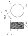
図2(a)から図2(c)を参照すると、実質的に構造体20と同じである代替の構造体50が示されている。図2(a)から図2(c)に示されている態様では、構造体50は第1の弾性材料の第1と第2のバンド52、54を含み、それらの間に配置される第2の弾性材料の第3のバンド56を有する。
【0029】
第1と第2のバンド52、54は、約1インチ(約25.4mm)幅であり、約3インチ(約76mm)の間隔をあけられている。第3のバンド56は、従って3インチ幅である。
【0030】
第1と第2のバンド52、54の第1の弾性材料は、典型的には第3のバンド56の第2の弾性材料よりも硬い。図2(a)から図2(c)で示される態様では、第1の弾性材料は、90デュロメーターの硬さのゴムからなり、ならびに第2の弾性材料は、60デュロメーターの硬さのゴムからなる。
【0031】
構造体20と違って、バンド52、54、56の厚さは、実質的に同じである。特に図2(c)から見て取られるように、第3のバンド56の外面56sはプロファイリングされている。外面56sは、中に拡張可能な導管12が設置される第2の導管(例えば、ライナー又はケーシング等の予め設置された部分、あるいは抗井構造)の内面に対する第3のバンド56のグリップを強くするのにリブを付けられている。第1と第2のバンド52、54の外面も、プロファイリング(例えばリブ)されても良いことが認識されよう。
【0032】
硬い方のゴムである2つの外側のバンド52、54は、比較的高温のシール及び比較的柔らかい方の第3のバンド56のゴムに対するバックアップのシールを提供する。第3のバンド56は、典型的にはより低温のシールを提供する。
【0033】
使用に際して、構造体20、50は、(拡張していない)拡張可能な導管12の外面12sに適用される。構造体20、50は、拡張可能な導管12の長さに沿って軸方向に間隔をあけた位置に適用されれば良く、構造体20、50の間隔及び個数は、その特定の用途に合わせて選ばれる。
【0034】
次いで、拡張可能な導管12が、ボアホール、ケーシング又はライナー14、あるいは拡張可能な導管12が装着されるべき何らかの他の導管の中に入れられる。図1(上部)で見られるように、拡張可能な導管12がケーシング又はライナー14の中に入れられると、環状部30が、導管12の外面12sと、ケーシング又はライナー14の内面14iとの間にできる。エキスパンダ装置18は、導管12がケーシング又はライナー14の中に入れられる前に、拡張可能な導管12の拡張した部分12eに設置されるのが典型的である。導管12は、拡張可能な導管12が半径方向に拡張する場合でも、(サイズは縮小するが)環状部30が残る、すなわち、拡張可能な導管12とケーシング又はライナー14との間に間隙がある非干渉(ノンインターフィーランス、non−interference)のタイプであることに留意されるべきである。拡張可能な導管12は非干渉のタイプである必要はない。
【0035】
拡張可能な導管12の外面12sは、ケーシング又はライナー14の内面14iと直接接触していないので、拡張可能な導管12の少なくとも一部が半径方向に拡張させられる間、機械的な、あるいは他のタイプの固定具32(例えばスリップ)が一時的なアンカーを提供するのに用いられる。機械的な、あるいは他のタイプの固定具32は、いずれかの一般的なタイプであって良く、典型的には拡張可能な導管12の拡張した部分12eに、あるいはその近くに装着される。
【0036】
機械的な、あるいは他のタイプの固定具32がセットされると、エキスパンダ装置18は、拡張可能な導管12中を矢印34の方向に押され、あるいは引かれる。エキスパンダ装置18は、拡張可能な導管12中を流体の圧力を用いて進まされて良く、あるいは拡張可能な導管12に沿って一般的なピッグ又はトラックター(不図示)を用いてピッグされて良い。エキスパンダ装置18は、代わりに(例えばストリングからの)重さを用いて進められて良く、あるいは(例えば、ドリルパイプ、ロッド、コイルドチュービング、又はワイヤーライン等を用いて)拡張可能な導管12中を引かれて良い。
【0037】
エキスパンダ装置18が(いずれかの一般的な方法を用いて)拡張可能な導管12に沿って進められると、図1の下部に図示されているように、それは導管12を半径方向に拡張する。導管12が拡張させられると、構造体20、50も拡張させられ、それにより、構造体20、50(すなわち、第1、第2、及び第3のバンド22、24、28、52、54、56のゴム)が、ケーシング又はライナー14の内面14iの一部と係合する。第1と第2のゴム(すなわち、バンド22、24、52、54)の外面と、任意選択で、固定及び/又はシールするのを強めるのにプロファイリング(例えば、リブ等)されている第3のゴム(すなわち、バンド28、56)とを有するのが有利である。
【0038】
第1、第2、及び第3のバンド22、24、28、52、54、56のゴムが、ケーシング又はライナー14の内面14iと係合すると、それらは、第1及び/又は第2のゴムと内面14iとの間に引き起こされる摩擦によるアンカー箇所を提供する。このアンカー箇所は、拡張可能な導管12をケーシング又はライナー14に固定する。
【0039】
加えて、第1及び/又は第2のゴムが、環状部30をシールする環状の圧力シールに結果としてなるシールとして働いても良い。2つ以上の構造体20、50が軸方向に間隔をあけた位置に設けられている場合には、その構造体20、50の間の環状部30の部分は、お互いに隔てられることになる。
【0040】
構造体20、50が拡張させられ、それにより、第1と第2のゴムが拡張可能なケーシング12のための少なくとも一つのアンカー箇所(及び任意選択で環状部30のためのシール)を提供した後に、機械的な、あるいは他のタイプの固定具32が解除され、そして任意選択でケーシング又はライナー14から取り外される。
【0041】
図3を参照すると、代替の拡張可能な導管100、すなわち本発明の装置の第2の態様が示されている。拡張可能な導管100は、拡張可能な導管12と実質的に同じであるが、その外面100sにさらなる代替の構造体150を有する。
【0042】
拡張可能な導管100は、少なくとも10%まで半径方向に拡張させることができる塑性変形に耐えることのできるいずれかのタイプの適当な導管であれば良いが、ただしこれよりも大きい又は小さい値まで半径方向に拡張されて良い。
【0043】
図3から見て取れるように、拡張可能な導管100は、導管100がボアホール等に入れられる間にエキスパンダ装置(例えば、エキスパンダ装置18)が設置される予め拡張した部分100eを備えている。エキスパンダ装置は、導管100がボアホールに入れられている間に導管内に設置される必要はなく、導管100が適所になったら導管内に設置させることができることに留意されるべきである。
【0044】
図3に示されているように、拡張可能な導管100は、概ね150で示される、少なくとも一つの構造体を備える。多くの構造体150が、導管100の外面100sに適用されているのが示されており、それぞれの構造体は、約12インチ(約305mm)まで、お互い軸方向に離されている。
【0045】
構造体150は、図4(a)及び図4(b)に最も良く示されている。その代替の構造体150は、ジグザグの形状である。この態様では、その又はそれぞれの構造体150は、例えば90デュロメーターの硬さであり、ならびに約0.12インチ(約3mm)の厚さで約2.5インチ(約28mm)幅であるゴムの一本のバンドからなる。
【0046】
ジグザグのパターンを付与し、それ故に構造体150が使用に際してもたらすグリップ及び/又はシールの強度を強くするのに、いくつかのスロット152a、152b(例えば20個)が、ゴムのバンドに施される。スロット152a、152bは、典型的には約2インチ(約50mm)の長さで、約0.2インチ(約5mm)幅である。
【0047】
スロット152aは、約20個、円周上に間隔をあけた位置に、それぞれの間を約18°とされ、バンドの一方の縁150aに沿って施される。その後、その処理が、バンドのもう一方のサイド150bに別の20個のスロット152bを施すことにより繰り返され、そのもう一方のサイドのスロットは、他方のサイドのスロット152aから周辺上で9°ずらされている。
【0048】
使用に際し、構造体150は、(拡張していない)拡張可能な導管100の外面100sに適用される。構造体150は、図3で見られるように、拡張可能な導管100の長さに沿って軸方向に間隔をあけた位置に適用されて良く、構造体100の間隔及び個数は、特定の用途に合わせて選ばれる。
【0049】
その後、拡張可能な導管100はボアホールか、ケーシング又はライナー14か、あるいは拡張可能な導管100が装着されるべき何れかの他の導管に入れられ、上記の導管12と実質的に同じ方法で使用される。
【0050】
拡張可能な導管を第2の導管に固定するための、ここで記載の方法及び装置を使用することで、構造体を備える拡張可能な導管を使用し抗井をケースすることが、セメントを用いずに可能になる。これは、必要な材料及び掘削装置の中断時間の削減により特にコストの点で顕著な利点を有する。
【0051】
このように、拡張可能な導管を第2の導管に固定する方法及び装置が提供される。ある態様の装置及び方法は、任意選択で、拡張可能な導管と第2の導管の間にシールを提供する。ある態様の装置は、特別に配置され、かつ構成されている、弾性材料からなる様々な層又はバンドの構造体を含み、拡張可能な導管と第2の導管の間に良好なアンカー及び/又はシールを提供する。
【0052】
改変及び改良が、本発明の範囲から外れないで、上記のものになされて良い。
【図面の簡単な説明】
【図1】 拡張可能な導管をボアホールに固定するための装置の例示的な態様の概略断面図である。
【図2】 (a) 図1の装置の外面に適用される構造体の第1の形状を示している正面図である。
(b) 図2(a)の構造体の端面図である。
(c) プロファイリングされた外面を示している、図2(a)及び図2(b)の構造体の一部の拡大図である。
【図3】 外面に異なる構造体を有し、拡張可能な導管をボアホールに固定するための装置の代替の態様の概略断面図である。
【図4】 (a) 図3の構造体の正面図である。
(b) 図4(a)の構造体の端面図である。
【符号の説明】
12…拡張可能な導管、 12e…拡張した部分、 12s…外面、 14…ケーシング又はライナー、 14i…内面、 16…地層、 18…エキスパンダ装置、 20…構造体、 22、24、28…バンド、 26…長さ方向の軸、 30…環状部、 32…固定具、 34…矢印、 50…構造体、 52、54、56…バンド、 56s…外面、 100…拡張可能な導管、 100s…外面、 150…構造体、 150a、150b…バンドのサイド(縁)、 152a、152b…スロット。[0001]
The present invention relates to an apparatus and method for securing an expandable conduit to a second conduit in which, but not limited to, an expandable conduit is installed.
[0002]
Conventionally, during the recovery of hydrocarbons from a well, a borehole is drilled, which is typically lined with a casing that is cemented in place with cement. The casing is installed to prevent the formation around the borehole from collapsing. In addition, the casing prevents unwanted fluid from the surrounding formation from flowing into the borehole, and similarly prevents fluid in the borehole from flowing out to the surrounding formation.
[0003]
It is known to use a flexible casing that can be radially expanded so that the outer surface of the casing contacts the formation around the borehole. A flexible casing typically plastically deforms when expanded by passing an expander device such as a ceramic or steel cone through the casing. The expander device is advanced along the casing in the same way as a pipeline pig and can be pushed (eg, using fluid pressure) or (drill pipe, rod, coiled tubing, or wire line) Etc.) may be used.
[0004]
Several expandable casings are connected to each other to make a casing string (typically by a screw connection). The casing string is placed in the borehole in an unexpanded state and subsequently expanded using an expander device. However, the unexpanded casing string needs to be secured at either its upper end or lower end prior to and / or during the expansion process.
[0005]
According to a first aspect of the present invention, there is provided an apparatus for securing an expandable conduit, the apparatus including at least one structure mounted on an outer surface of the expandable conduit, the structure being a medium. An anchor for the expandable conduit and / or an anchor for the expandable conduit when the expandable conduit is at least partially expanded. Or provide a seal.
[0006]
According to a second aspect of the present invention, there is provided a method of securing an expandable conduit, the method providing an expandable conduit having at least one structure on its outer surface, the structure being inside The expandable conduit can be engaged with a second conduit to provide an anchor and / or seal for the expandable conduit, securing the expandable conduit to the second conduit; And expanding at least a portion of the expandable conduit to bring the structure into contact with the second conduit.
[0007]
The present invention also provides an expandable conduit, such as a casing, and when the expandable conduit is expanded, the conduit is on its outer surface adapted to engage the second member. It has a structure.
[0008]
The structure typically consists of first and second bands of elastic material, a first elastic material such as rubber, the first and second bands being axially spaced. And a third band of second elastic material, such as a second rubber, is disposed between the first and second bands. The first material is preferably harder than the second material. The first and / or second material may be profiled on its outer surface to strengthen the anchor and / or seal.
[0009]
In one particular aspect of the invention, the first and second bands comprise 2 inch (about 51 millimeters) wide bands and are spaced 10 inches (about 250 millimeters) wide. The third band typically comprises a 10 inch (about 250 millimeters) wide band. The first rubber is typically a 60 durometer rubber. The second rubber is typically a 40 durometer rubber. The rubber band can be any suitable hardness and width. Alternatively, the first rubber can be a 90 durometer rubber and the second rubber can be a 60 durometer rubber.
[0010]
In one alternative aspect, the structure comprises a band of rubber or other suitable elastic material. The band preferably forms a zigzag pattern on the surface of the conduit. The rubber can be any suitable hardness, but is typically about 40 to 90 durometers, although numerical hardness outside this range may be used.
[0011]
The material properties and shape of the or each structure can be selected for a particular application.
[0012]
The expandable conduit typically consists of an expandable casing or liner. However, the expandable conduit may be any suitable expandable pipe or the like.
[0013]
The structure is optionally removable and is preferably applied to the outer surface of the conduit before the conduit is expanded. The structure optionally comprises two or more axially spaced structures.
[0014]
The second conduit typically includes a bore hole, a casing, a liner, or the like. The expandable casing may engage any type of conduit.
[0015]
The method of the present invention typically includes the additional step of providing an expander device for radially expanding the expandable conduit.
[0016]
The expander device typically includes a corn. The expander device may be made from steel. Alternatively, the expander device may be made from a ceramic material or a combination of steel and ceramic material. The expander device is optional and flexible.
[0017]
The expandable conduit is temporarily secured to the second conduit, typically using mechanical or other fasteners (eg, slips).
[0018]
Aspects of the invention are described below by way of example only and with reference to the accompanying drawings.
[0019]
Referring to the drawings, FIG. 1 illustrates an exemplary embodiment of an apparatus for securing an
[0020]
The
[0021]
The upper portion of FIG. 1 shows an
[0022]
The
[0023]
As shown in FIG. 1, the
[0024]
Arranged between the first and
[0025]
The first and
[0026]
The first type of rubber (ie, the first and
[0027]
The particular nature of the rubber may be of any suitable type, and the hardness shown is merely exemplary. It should also be noted that the size and spacing of each of the first, second, and
[0028]
Referring to FIGS. 2 (a) to 2 (c), an
[0029]
The first and
[0030]
The first elastic material of the first and
[0031]
Unlike the
[0032]
The two
[0033]
In use, the
[0034]
The
[0035]
The
[0036]
When a mechanical or other type of
[0037]
As the
[0038]
When the rubber of the first, second, and
[0039]
In addition, the first and / or second rubber may act as a seal resulting in an annular pressure seal that seals the annular portion 30. When two or
[0040]
The
[0041]
Referring to FIG. 3, there is shown an alternative
[0042]
The
[0043]
As can be seen from FIG. 3, the
[0044]
As shown in FIG. 3, the
[0045]
The
[0046]
A number of
[0047]
About 20
[0048]
In use, the
[0049]
The
[0050]
Using a method and apparatus described herein for securing an expandable conduit to a second conduit, using an expandable conduit with a structure to case a well using a cement It becomes possible without. This has significant advantages, especially in terms of cost, due to the reduction of required materials and drilling equipment interruption time.
[0051]
Thus, a method and apparatus for securing an expandable conduit to a second conduit is provided. Certain aspects of the apparatus and method optionally provide a seal between the expandable conduit and the second conduit. An apparatus of an aspect includes a structure of various layers or bands of elastic material that is specially arranged and configured to provide a good anchor and / or between an expandable conduit and a second conduit. Provide a seal.
[0052]
Modifications and improvements may be made to the above without departing from the scope of the invention.
[Brief description of the drawings]
FIG. 1 is a schematic cross-sectional view of an exemplary embodiment of an apparatus for securing an expandable conduit to a borehole.
2A is a front view showing a first shape of a structure applied to the outer surface of the apparatus of FIG. 1; FIG.
(B) It is an end view of the structure of Fig.2 (a).
(C) Enlarged view of a portion of the structure of FIGS. 2 (a) and 2 (b) showing the profiled outer surface.
FIG. 3 is a schematic cross-sectional view of an alternative embodiment of an apparatus for securing an expandable conduit to a borehole having a different structure on the outer surface.
4A is a front view of the structure shown in FIG.
(B) It is an end view of the structure of Fig.4 (a).
[Explanation of symbols]
12 ... Expandable conduit, 12e ... Expanded part, 12s ... Outer surface, 14 ... Casing or liner, 14i ... Inner surface, 16 ... Formation, 18 ... Expander device, 20 ... Structure, 22, 24, 28 ... Band, 26 ... Axis of length, 30 ... annular part, 32 ... fixing device, 34 ... arrow, 50 ... structure, 52, 54, 56 ... band, 56s ... outer surface, 100 ... expandable conduit, 100s ...
Claims (7)
前記構造体16、50が、第1の弾性材料の第1と第2のバンド22、24、52、54からなり、
前記第1と第2のバンド22、24、52、54が、軸方向に間隔をあけられており、第2の弾性材料の第3のバンド28、56が、前記第1と第2のバンド22、24、52、54の間に配置され、前記第1の弾性材料が、前記第2の弾性材料よりも硬いものであることを特徴とする拡張可能な導管を固定するための装置。An apparatus for securing an expandable conduit, the apparatus comprising at least one structure 16, 50 mounted on an outer surface 12s of the expandable conduit 12, the structure 16, 50 being a medium Can be engaged with a second conduit 14 in which the expandable conduit 12 is installed, and when the expandable conduit 12 is at least partially expanded, the structures 16, 50 Providing an anchor and / or seal for the expandable conduit 12;
The structures 16, 50 are composed of first and second bands 22, 24, 52, 54 of a first elastic material,
The first and second bands 22, 24, 52, 54 are spaced apart in the axial direction, and the third bands 28, 56 of second elastic material are the first and second bands. An apparatus for securing an expandable conduit disposed between 22, 24, 52, 54 , wherein the first elastic material is harder than the second elastic material .
前記構造体16、50は、第1の弾性材料の第1と第2のバンド22、24、52、54からなり、
前記第1と第2のバンド22、24、52、54が軸方向に間隔をあけられており、
前記構造体16、50は、前記第1と第2のバンド22、24、52、54の間に配置された第2の弾性材料の第3のバンド28、56を含み、前記第1の弾性材料が、前記第2の弾性材料よりも硬いものであることを特徴とする拡張可能な導管を含む装置。An apparatus including an expandable conduit, wherein the outer surface 12s has a structure 16, 50 adapted to engage the second conduit 14 when the expandable conduit 12 is expanded. Have
The structures 16, 50 are composed of first and second bands 22, 24, 52, 54 of a first elastic material,
The first and second bands 22, 24, 52, 54 are spaced apart in the axial direction;
The structure 16, 50, the first and third bands 28,56 viewed free of a second elastic material disposed between the second band 22,24,52,54, the first An apparatus comprising an expandable conduit , wherein the elastic material is stiffer than the second elastic material .
前記構造体16、50は、第1の弾性材料の第1と第2のバンド22、24、52、54を含み、
前記第1と第2のバンド22、24、52、54は、軸方向に間隔があけられてあり、
前記構造体16、50は、前記第1と第2のバンド22、24、52、54の間に配置された第2の弾性材料の第3のバンド28、56を含み、前記第1の弾性材料が、前記第2の弾性材料よりも硬いものであり、
前記構造体16、50は中に前記拡張可能な導管12が設置される第2の導管14と係合して前記拡張可能な導管12のためのアンカー及び/又はシールを提供することができ、前記拡張可能な導管12を前記第2の導管14に固定し、そして前記構造体16、50を前記第2の導管14と接触させるのに前記拡張可能な導管12の少なくとも一部を拡張する工程を含むことを特徴とする拡張可能な導管を固定する方法。A method of securing an expandable conduit, the method providing the expandable conduit 12 having at least one structure 16, 50 on its outer surface 12s;
The structures 16, 50 include first and second bands 22, 24, 52, 54 of a first elastic material,
The first and second bands 22, 24, 52, 54 are axially spaced,
The structures 16, 50 include third bands 28, 56 of a second elastic material disposed between the first and second bands 22, 24, 52, 54, and the first elastic The material is harder than the second elastic material;
The structures 16, 50 can engage a second conduit 14 in which the expandable conduit 12 is installed to provide an anchor and / or seal for the expandable conduit 12, Securing the expandable conduit 12 to the second conduit 14 and expanding at least a portion of the expandable conduit 12 to bring the structures 16, 50 into contact with the second conduit 14; A method of securing an expandable conduit characterized by comprising:
Applications Claiming Priority (3)
| Application Number | Priority Date | Filing Date | Title |
|---|---|---|---|
| GBGB9920936.3A GB9920936D0 (en) | 1999-09-06 | 1999-09-06 | Apparatus for and a method of anchoring an expandable conduit |
| GB9920936.3 | 1999-09-06 | ||
| PCT/GB2000/003407 WO2001018355A1 (en) | 1999-09-06 | 2000-09-06 | Apparatus for and a method of anchoring an expandable conduit |
Publications (3)
| Publication Number | Publication Date |
|---|---|
| JP2003508662A JP2003508662A (en) | 2003-03-04 |
| JP2003508662A5 JP2003508662A5 (en) | 2007-10-25 |
| JP4689911B2 true JP4689911B2 (en) | 2011-06-01 |
Family
ID=10860364
Family Applications (1)
| Application Number | Title | Priority Date | Filing Date |
|---|---|---|---|
| JP2001521869A Expired - Fee Related JP4689911B2 (en) | 1999-09-06 | 2000-09-06 | Apparatus and method for securing an expandable conduit |
Country Status (14)
| Country | Link |
|---|---|
| US (2) | US6789622B1 (en) |
| EP (2) | EP1210503B1 (en) |
| JP (1) | JP4689911B2 (en) |
| AU (1) | AU780057B2 (en) |
| CA (1) | CA2390585C (en) |
| DE (1) | DE60031693T2 (en) |
| DK (1) | DK1210503T3 (en) |
| EA (1) | EA003447B1 (en) |
| GB (1) | GB9920936D0 (en) |
| MX (1) | MXPA02002421A (en) |
| NO (1) | NO332064B1 (en) |
| NZ (1) | NZ517492A (en) |
| OA (1) | OA12014A (en) |
| WO (1) | WO2001018355A1 (en) |
Families Citing this family (40)
| Publication number | Priority date | Publication date | Assignee | Title |
|---|---|---|---|---|
| GB2384502B (en) * | 1998-11-16 | 2004-10-13 | Shell Oil Co | Coupling an expandable tubular member to a preexisting structure |
| EP2273064A1 (en) * | 1998-12-22 | 2011-01-12 | Weatherford/Lamb, Inc. | Procedures and equipment for profiling and jointing of pipes |
| GB9920936D0 (en) * | 1999-09-06 | 1999-11-10 | E2 Tech Ltd | Apparatus for and a method of anchoring an expandable conduit |
| US6789621B2 (en) | 2000-08-03 | 2004-09-14 | Schlumberger Technology Corporation | Intelligent well system and method |
| GB2389606B (en) * | 2000-12-22 | 2005-06-29 | E2Tech Ltd | Method and apparatus for downhole remedial or repair operations |
| GB0109711D0 (en) | 2001-04-20 | 2001-06-13 | E Tech Ltd | Apparatus |
| GB0111413D0 (en) * | 2001-05-09 | 2001-07-04 | E Tech Ltd | Apparatus and method |
| US6648075B2 (en) | 2001-07-13 | 2003-11-18 | Weatherford/Lamb, Inc. | Method and apparatus for expandable liner hanger with bypass |
| US6820690B2 (en) * | 2001-10-22 | 2004-11-23 | Schlumberger Technology Corp. | Technique utilizing an insertion guide within a wellbore |
| US20030075337A1 (en) * | 2001-10-24 | 2003-04-24 | Weatherford/Lamb, Inc. | Method of expanding a tubular member in a wellbore |
| US6681862B2 (en) | 2002-01-30 | 2004-01-27 | Halliburton Energy Services, Inc. | System and method for reducing the pressure drop in fluids produced through production tubing |
| WO2003074837A1 (en) * | 2002-03-04 | 2003-09-12 | Shell Internationale Research Maatschappij B.V. | Expandable well tubing |
| GB0206256D0 (en) * | 2002-03-16 | 2002-05-01 | Downhole Products Plc | Apparatus |
| US6854521B2 (en) | 2002-03-19 | 2005-02-15 | Halliburton Energy Services, Inc. | System and method for creating a fluid seal between production tubing and well casing |
| US7341110B2 (en) * | 2002-04-05 | 2008-03-11 | Baker Hughes Incorporated | Slotted slip element for expandable packer |
| GB0215659D0 (en) | 2002-07-06 | 2002-08-14 | Weatherford Lamb | Formed tubulars |
| US7124829B2 (en) * | 2002-08-08 | 2006-10-24 | Tiw Corporation | Tubular expansion fluid production assembly and method |
| US7093656B2 (en) * | 2003-05-01 | 2006-08-22 | Weatherford/Lamb, Inc. | Solid expandable hanger with compliant slip system |
| US7028780B2 (en) * | 2003-05-01 | 2006-04-18 | Weatherford/Lamb, Inc. | Expandable hanger with compliant slip system |
| GB0311721D0 (en) | 2003-05-22 | 2003-06-25 | Weatherford Lamb | Tubing connector |
| US7607476B2 (en) * | 2006-07-07 | 2009-10-27 | Baker Hughes Incorporated | Expandable slip ring |
| US8069916B2 (en) | 2007-01-03 | 2011-12-06 | Weatherford/Lamb, Inc. | System and methods for tubular expansion |
| US9551201B2 (en) | 2008-02-19 | 2017-01-24 | Weatherford Technology Holdings, Llc | Apparatus and method of zonal isolation |
| AU2009215521B2 (en) | 2008-02-19 | 2012-05-24 | Weatherford Technology Holdings, Llc | Expandable packer |
| GB2485504B (en) * | 2009-08-28 | 2013-11-06 | Enventure Global Technology | System and method for anchoring an expandable tubular to a borehole wall |
| WO2011023743A2 (en) * | 2009-08-28 | 2011-03-03 | Shell Internationale Research Maatschappij B.V. | System and method for anchoring an expandable tubular to a borehole wall |
| GB2486099B (en) * | 2009-08-28 | 2013-06-19 | Shell Int Research | System and method for anchoring an expandable tubular to a borehole wall |
| US20120205092A1 (en) | 2011-02-16 | 2012-08-16 | George Givens | Anchoring and sealing tool |
| US9528352B2 (en) | 2011-02-16 | 2016-12-27 | Weatherford Technology Holdings, Llc | Extrusion-resistant seals for expandable tubular assembly |
| US11215021B2 (en) | 2011-02-16 | 2022-01-04 | Weatherford Technology Holdings, Llc | Anchoring and sealing tool |
| WO2012112823A2 (en) | 2011-02-16 | 2012-08-23 | Weatherford/Lamb, Inc. | Stage tool |
| CA2827462C (en) | 2011-02-16 | 2016-01-19 | Weatherford/Lamb, Inc. | Anchoring seal |
| US9260926B2 (en) | 2012-05-03 | 2016-02-16 | Weatherford Technology Holdings, Llc | Seal stem |
| US9810037B2 (en) | 2014-10-29 | 2017-11-07 | Weatherford Technology Holdings, Llc | Shear thickening fluid controlled tool |
| US10180038B2 (en) | 2015-05-06 | 2019-01-15 | Weatherford Technology Holdings, Llc | Force transferring member for use in a tool |
| CN104879101B (en) * | 2015-05-11 | 2018-01-05 | 中国石油天然气股份有限公司 | Full well section expandable screen |
| WO2017112884A2 (en) * | 2015-12-22 | 2017-06-29 | Mohawk Energy Ltd. | Expandable anchor sleeve |
| GB2597137B (en) | 2016-02-10 | 2022-04-13 | Mohawk Energy Ltd | Expandable anchor sleeve |
| US20230323745A1 (en) * | 2022-04-08 | 2023-10-12 | Baker Hughes Oilfield Operations Llc | Liner system and method |
| US11898423B2 (en) * | 2022-04-08 | 2024-02-13 | Baker Hughes Oilfield Operations | Liner system and method |
Citations (4)
| Publication number | Priority date | Publication date | Assignee | Title |
|---|---|---|---|---|
| JPS56125594A (en) * | 1979-08-20 | 1981-10-01 | Otis Eng Corp | Apparatus for fixing liner string in oil well |
| JPH10512636A (en) * | 1995-01-16 | 1998-12-02 | シエル・インターナシヨナル・リサーチ・マートスハツペイ・ベー・ヴエー | Construction method of casing in borehole |
| GB2345308A (en) * | 1998-12-22 | 2000-07-05 | Petroline Wellsystems Ltd | Tubing hanger |
| JP2001508144A (en) * | 1996-07-01 | 2001-06-19 | シエル・インターナシヨネイル・リサーチ・マーチヤツピイ・ベー・ウイ | Method of expanding steel tubing and wells having such tubing |
Family Cites Families (25)
| Publication number | Priority date | Publication date | Assignee | Title |
|---|---|---|---|---|
| US1880218A (en) * | 1930-10-01 | 1932-10-04 | Richard P Simmons | Method of lining oil wells and means therefor |
| US2017451A (en) * | 1933-11-21 | 1935-10-15 | Baash Ross Tool Co | Packing casing bowl |
| US3353599A (en) * | 1964-08-04 | 1967-11-21 | Gulf Oil Corp | Method and apparatus for stabilizing formations |
| US3529667A (en) * | 1969-01-10 | 1970-09-22 | Lynes Inc | Inflatable,permanently set,drillable element |
| US3776307A (en) * | 1972-08-24 | 1973-12-04 | Gearhart Owen Industries | Apparatus for setting a large bore packer in a well |
| FR2717855B1 (en) * | 1994-03-23 | 1996-06-28 | Drifflex | Method for sealing the connection between an inner liner on the one hand, and a wellbore, casing or an outer pipe on the other. |
| US6085838A (en) * | 1997-05-27 | 2000-07-11 | Schlumberger Technology Corporation | Method and apparatus for cementing a well |
| US6021850A (en) * | 1997-10-03 | 2000-02-08 | Baker Hughes Incorporated | Downhole pipe expansion apparatus and method |
| US6098717A (en) * | 1997-10-08 | 2000-08-08 | Formlock, Inc. | Method and apparatus for hanging tubulars in wells |
| US6135208A (en) * | 1998-05-28 | 2000-10-24 | Halliburton Energy Services, Inc. | Expandable wellbore junction |
| US6745845B2 (en) * | 1998-11-16 | 2004-06-08 | Shell Oil Company | Isolation of subterranean zones |
| US6712154B2 (en) * | 1998-11-16 | 2004-03-30 | Enventure Global Technology | Isolation of subterranean zones |
| GB2344606B (en) * | 1998-12-07 | 2003-08-13 | Shell Int Research | Forming a wellbore casing by expansion of a tubular member |
| AU766437B2 (en) * | 1998-12-22 | 2003-10-16 | Weatherford/Lamb Inc. | Downhole sealing for production tubing |
| EP2273064A1 (en) * | 1998-12-22 | 2011-01-12 | Weatherford/Lamb, Inc. | Procedures and equipment for profiling and jointing of pipes |
| ID30263A (en) * | 1999-04-09 | 2001-11-15 | Shell Int Research | METHOD FOR CIRCLE SEALING |
| GB9920936D0 (en) * | 1999-09-06 | 1999-11-10 | E2 Tech Ltd | Apparatus for and a method of anchoring an expandable conduit |
| CA2329388C (en) * | 1999-12-22 | 2008-03-18 | Smith International, Inc. | Apparatus and method for packing or anchoring an inner tubular within a casing |
| US6598678B1 (en) * | 1999-12-22 | 2003-07-29 | Weatherford/Lamb, Inc. | Apparatus and methods for separating and joining tubulars in a wellbore |
| WO2003021080A1 (en) * | 2001-09-05 | 2003-03-13 | Weatherford/Lamb, Inc. | High pressure high temperature packer system and expansion assembly |
| US20030042028A1 (en) * | 2001-09-05 | 2003-03-06 | Weatherford/Lamb, Inc. | High pressure high temperature packer system |
| US6691789B2 (en) * | 2001-09-10 | 2004-02-17 | Weatherford/Lamb, Inc. | Expandable hanger and packer |
| US6814143B2 (en) * | 2001-11-30 | 2004-11-09 | Tiw Corporation | Downhole tubular patch, tubular expander and method |
| US6629567B2 (en) * | 2001-12-07 | 2003-10-07 | Weatherford/Lamb, Inc. | Method and apparatus for expanding and separating tubulars in a wellbore |
| US6854522B2 (en) * | 2002-09-23 | 2005-02-15 | Halliburton Energy Services, Inc. | Annular isolators for expandable tubulars in wellbores |
-
1999
- 1999-09-06 GB GBGB9920936.3A patent/GB9920936D0/en not_active Ceased
-
2000
- 2000-09-06 WO PCT/GB2000/003407 patent/WO2001018355A1/en active IP Right Grant
- 2000-09-06 EA EA200200343A patent/EA003447B1/en not_active IP Right Cessation
- 2000-09-06 DE DE60031693T patent/DE60031693T2/en not_active Expired - Lifetime
- 2000-09-06 OA OA1200200062A patent/OA12014A/en unknown
- 2000-09-06 CA CA002390585A patent/CA2390585C/en not_active Expired - Fee Related
- 2000-09-06 MX MXPA02002421A patent/MXPA02002421A/en unknown
- 2000-09-06 JP JP2001521869A patent/JP4689911B2/en not_active Expired - Fee Related
- 2000-09-06 US US10/069,990 patent/US6789622B1/en not_active Expired - Lifetime
- 2000-09-06 DK DK00958792T patent/DK1210503T3/en active
- 2000-09-06 EP EP00958792A patent/EP1210503B1/en not_active Expired - Lifetime
- 2000-09-06 EP EP04025377A patent/EP1500784A2/en not_active Withdrawn
- 2000-09-06 NZ NZ517492A patent/NZ517492A/en not_active IP Right Cessation
- 2000-09-06 AU AU70211/00A patent/AU780057B2/en not_active Ceased
-
2002
- 2002-03-05 NO NO20021082A patent/NO332064B1/en not_active IP Right Cessation
-
2004
- 2004-07-19 US US10/894,302 patent/US20040256098A1/en not_active Abandoned
Patent Citations (4)
| Publication number | Priority date | Publication date | Assignee | Title |
|---|---|---|---|---|
| JPS56125594A (en) * | 1979-08-20 | 1981-10-01 | Otis Eng Corp | Apparatus for fixing liner string in oil well |
| JPH10512636A (en) * | 1995-01-16 | 1998-12-02 | シエル・インターナシヨナル・リサーチ・マートスハツペイ・ベー・ヴエー | Construction method of casing in borehole |
| JP2001508144A (en) * | 1996-07-01 | 2001-06-19 | シエル・インターナシヨネイル・リサーチ・マーチヤツピイ・ベー・ウイ | Method of expanding steel tubing and wells having such tubing |
| GB2345308A (en) * | 1998-12-22 | 2000-07-05 | Petroline Wellsystems Ltd | Tubing hanger |
Also Published As
| Publication number | Publication date |
|---|---|
| EA003447B1 (en) | 2003-06-26 |
| DK1210503T3 (en) | 2007-03-05 |
| DE60031693D1 (en) | 2006-12-14 |
| US20040256098A1 (en) | 2004-12-23 |
| EA200200343A1 (en) | 2002-10-31 |
| NZ517492A (en) | 2003-08-29 |
| MXPA02002421A (en) | 2005-06-06 |
| OA12014A (en) | 2006-04-19 |
| GB9920936D0 (en) | 1999-11-10 |
| DE60031693T2 (en) | 2007-10-04 |
| NO332064B1 (en) | 2012-06-11 |
| CA2390585C (en) | 2008-08-19 |
| US6789622B1 (en) | 2004-09-14 |
| EP1210503A1 (en) | 2002-06-05 |
| EP1500784A2 (en) | 2005-01-26 |
| WO2001018355A1 (en) | 2001-03-15 |
| NO20021082L (en) | 2002-03-13 |
| AU7021100A (en) | 2001-04-10 |
| NO20021082D0 (en) | 2002-03-05 |
| JP2003508662A (en) | 2003-03-04 |
| AU780057B2 (en) | 2005-02-24 |
| EP1210503B1 (en) | 2006-11-02 |
| CA2390585A1 (en) | 2001-03-15 |
Similar Documents
| Publication | Publication Date | Title |
|---|---|---|
| JP4689911B2 (en) | Apparatus and method for securing an expandable conduit | |
| CA2383150C (en) | Expandable downhole tubing | |
| US7124823B2 (en) | Apparatus for and method of anchoring a first conduit to a second conduit | |
| RU2477365C1 (en) | Anchors of swelling packers | |
| US7124821B2 (en) | Apparatus and method for expanding a tubular | |
| US7017669B2 (en) | Methods and apparatus for expanding tubulars | |
| US6942029B2 (en) | Tubing expansion | |
| BRPI1001364A2 (en) | expandable appliance upgrades | |
| US20120312561A1 (en) | Tubular assembly | |
| US20090308594A1 (en) | Method for expanding a tubular element | |
| US5280824A (en) | Sealing element for inflatable packer |
Legal Events
| Date | Code | Title | Description |
|---|---|---|---|
| A521 | Written amendment |
Free format text: JAPANESE INTERMEDIATE CODE: A523 Effective date: 20070904 |
|
| A621 | Written request for application examination |
Free format text: JAPANESE INTERMEDIATE CODE: A621 Effective date: 20070904 |
|
| A977 | Report on retrieval |
Free format text: JAPANESE INTERMEDIATE CODE: A971007 Effective date: 20090529 |
|
| A131 | Notification of reasons for refusal |
Free format text: JAPANESE INTERMEDIATE CODE: A131 Effective date: 20090924 |
|
| A521 | Written amendment |
Free format text: JAPANESE INTERMEDIATE CODE: A523 Effective date: 20091110 |
|
| A131 | Notification of reasons for refusal |
Free format text: JAPANESE INTERMEDIATE CODE: A131 Effective date: 20100406 |
|
| A521 | Written amendment |
Free format text: JAPANESE INTERMEDIATE CODE: A523 Effective date: 20100614 |
|
| TRDD | Decision of grant or rejection written | ||
| A01 | Written decision to grant a patent or to grant a registration (utility model) |
Free format text: JAPANESE INTERMEDIATE CODE: A01 Effective date: 20110208 |
|
| A01 | Written decision to grant a patent or to grant a registration (utility model) |
Free format text: JAPANESE INTERMEDIATE CODE: A01 |
|
| A61 | First payment of annual fees (during grant procedure) |
Free format text: JAPANESE INTERMEDIATE CODE: A61 Effective date: 20110217 |
|
| R150 | Certificate of patent or registration of utility model |
Free format text: JAPANESE INTERMEDIATE CODE: R150 |
|
| FPAY | Renewal fee payment (event date is renewal date of database) |
Free format text: PAYMENT UNTIL: 20140225 Year of fee payment: 3 |
|
| R250 | Receipt of annual fees |
Free format text: JAPANESE INTERMEDIATE CODE: R250 |
|
| R250 | Receipt of annual fees |
Free format text: JAPANESE INTERMEDIATE CODE: R250 |
|
| R250 | Receipt of annual fees |
Free format text: JAPANESE INTERMEDIATE CODE: R250 |
|
| R250 | Receipt of annual fees |
Free format text: JAPANESE INTERMEDIATE CODE: R250 |
|
| LAPS | Cancellation because of no payment of annual fees |