JP4689812B2 - Wireless mouse - Google Patents
Wireless mouse Download PDFInfo
- Publication number
- JP4689812B2 JP4689812B2 JP2000351459A JP2000351459A JP4689812B2 JP 4689812 B2 JP4689812 B2 JP 4689812B2 JP 2000351459 A JP2000351459 A JP 2000351459A JP 2000351459 A JP2000351459 A JP 2000351459A JP 4689812 B2 JP4689812 B2 JP 4689812B2
- Authority
- JP
- Japan
- Prior art keywords
- wireless mouse
- connector
- mouse
- secondary battery
- wireless
- Prior art date
- Legal status (The legal status is an assumption and is not a legal conclusion. Google has not performed a legal analysis and makes no representation as to the accuracy of the status listed.)
- Expired - Fee Related
Links
Images


Classifications
-
- G—PHYSICS
- G06—COMPUTING; CALCULATING OR COUNTING
- G06F—ELECTRIC DIGITAL DATA PROCESSING
- G06F3/00—Input arrangements for transferring data to be processed into a form capable of being handled by the computer; Output arrangements for transferring data from processing unit to output unit, e.g. interface arrangements
- G06F3/01—Input arrangements or combined input and output arrangements for interaction between user and computer
- G06F3/03—Arrangements for converting the position or the displacement of a member into a coded form
- G06F3/033—Pointing devices displaced or positioned by the user, e.g. mice, trackballs, pens or joysticks; Accessories therefor
- G06F3/038—Control and interface arrangements therefor, e.g. drivers or device-embedded control circuitry
-
- G—PHYSICS
- G06—COMPUTING; CALCULATING OR COUNTING
- G06F—ELECTRIC DIGITAL DATA PROCESSING
- G06F3/00—Input arrangements for transferring data to be processed into a form capable of being handled by the computer; Output arrangements for transferring data from processing unit to output unit, e.g. interface arrangements
- G06F3/01—Input arrangements or combined input and output arrangements for interaction between user and computer
- G06F3/03—Arrangements for converting the position or the displacement of a member into a coded form
- G06F3/033—Pointing devices displaced or positioned by the user, e.g. mice, trackballs, pens or joysticks; Accessories therefor
- G06F3/0354—Pointing devices displaced or positioned by the user, e.g. mice, trackballs, pens or joysticks; Accessories therefor with detection of 2D relative movements between the device, or an operating part thereof, and a plane or surface, e.g. 2D mice, trackballs, pens or pucks
- G06F3/03543—Mice or pucks
-
- G—PHYSICS
- G06—COMPUTING; CALCULATING OR COUNTING
- G06F—ELECTRIC DIGITAL DATA PROCESSING
- G06F2203/00—Indexing scheme relating to G06F3/00 - G06F3/048
- G06F2203/038—Indexing scheme relating to G06F3/038
- G06F2203/0384—Wireless input, i.e. hardware and software details of wireless interface arrangements for pointing devices
Description
【0001】
【発明の属する技術分野】
本発明はワイヤレスマウスユニット、ワイヤレスマウス及び受信装置に係り、特に、ワイヤレス通信によって表示画面中のカーソルを移動させる情報を送信する機能を有するワイヤレスマウス及びコンピュータと接続してありこのワイヤレスマウスからの情報を受信する受信装置、及び、ワイヤレスマウス及び受信装置とよりなるワイヤレスマウスユニットに関する。
【0002】
一般に、ワイヤレスマウスは、ワイヤの煩わしさが無いという利点があるけれども、ワイヤで接続されていないため、マウス自体に電源が内蔵してある必要がある。内蔵電源としては、乾電池又は充電可能である二次電池が使用される。
【0003】
また、マウスには、マウスを動かすと底面のボールがマウスパッド上を転がって回転して信号を送り出す構成である一般的なものの他に、近年、オプティカルセンサを使用した構成のものが実用化されつつある。ボールがマウスパッド上を転がるタイプのマウスは、ボールがマウスパッド上の埃を拾い、長く使用している間に、埃がマウスの内部に溜まり、ボールの回転が円滑で無くなり、修理が必要となってしまう。オプティカルセンサ装置を使用した構成のマウスでは、オプティカルセンサ装置がマウスパッドに対して非接触であるため、上記の埃の問題がなく、保守が不要であるという利点がある。しかし、発光ダイオード等を使用しているため、消費電力が高い。よって、乾電池式のワイヤレスマウスでは、乾電池の交換を頻繁に行う必要があり、経済的でない。そこで、二次電池式のワイヤレスマウスが好ましくなる。この場合でも、二次電池の電力の消費が多いため、使い勝手を良くするためには、充電等に工夫が必要となる。
【0004】
【従来の技術】
従来の二次電池を内蔵したワイヤレスマウスは、付属品として、専用の充電装置を備え、この充電装置にセットして二次電池を充電させていた。
【0005】
【発明が解決しようとする課題】
このため、ワイヤレスマウスユニットは、ワイヤレスマウス及び受信装置の他に、充電装置を有する構成となっており、嵩張り、使い勝手が良くなく、コスト高となっていた。
【0006】
また、従来のワイヤレスマウスは、ケーブルに接続した状態で使用することは出来なかった。このため、充電切れの場合には、マウスを使用することが出来ず、いざ使用しようとしたときに、二次電池の電圧が降下していた場合には、ワイヤレスマウスを使用することが出来ず、コンピュータを使用することが出来なくなり、不便であった。
【0007】
そこで、本発明は、上記課題を解決したワイヤレスマウスユニット、ワイヤレスマウス及び受信装置を提供することを目的とする。
【0008】
【課題を解決するための手段】
【0020】
請求項1の発明は、 コンピュータに通常時にコネクタケーブルを介して接続してある受信装置にワイヤレス通信によって表示画面中のカーソルを移動させる情報を送信する機能を有するワイヤレスマウスにおいて、
充電可能電池と、
上記受信装置にセットされたときに、該受信装置の充電用端子と接続される充電用端子とを有し、
発光素子と該発光素子より出て該ワイヤレスマウスが操作される面で反射した光を受光する光学式センサチップとよりなるオプティカルセンサ装置を有し、
且つ、上記発光素子より出た光の一部を受光する内部太陽電池を有し、
該内部太陽電池が、上記充電可能電池とともに前記オプティカルセンサ装置に昇圧回路を介して並列に接続してある構成とし、
上記受信装置にセットされた状態で、上記コンピュータからの電力によって、上記充電可能電池が前記昇圧回路を迂回して充電される構成とし、前記ワイヤレスマウスは非常時に前記コネクタケーブルが接続され上記充電可能電池が充電可能とされる構成とし、
たことを特徴としたものである。
【0021】
ワイヤレスマウスを使用を終了したのちに、ワイヤレスマウスをワイヤレスマウスセット部にセットして保管することが可能となり、且つ、この保管中に充電可能電池を充電することが可能となる。よって、ワイヤレスマウスは、充電可能電池が十分に充電されている状態で使用を開始することが出来る。
【0025】
内部太陽電池が発電した電力を、ワイヤレスマウスの動作及び充電可能電池の充電に利用することが可能となる。よって、充電可能電池の消耗が抑えられる。
【0035】
【発明の実施の形態】
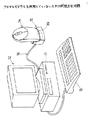
図1は本発明の一実施例になるワイヤレスマウスユニット10の通常の使用状態を示す。
【0036】
11はコンピュータ本体、12はCRTモニタに、13はキーボードである。14はワイヤレスマウス、15は受信装置である。受信装置15は、図7に示す一端にUSB雄コネクタ16、他端にコネクタ17を有するコネクタケーブル18によって、コンピュータ本体11と接続してある。
【0037】
ワイヤレスマウス14の操作を行うことによって、無線信号19が送信され、受信装置15がこの無線信号19を受信する。ワイヤレスマウス14を動かす操作を行うことによって、後述するオプティカルセンサ装置36が動作し、CRTモニタ12の表示画面20中のカーソル21が表示画面20上の任意の位置に移動され、ボタン31又は32を押すクリック操作を行うことによって、入力が行われる。
【0038】
ワイヤレスマウス14と受信装置15とコネクタケーブル18とが、ワイヤレスマウスユニット10を構成する。専用の充電器は備えていない。
【0039】
まず、ワイヤレスマウス14について説明する。
【0040】
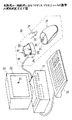
図2(A),(B)にワイヤレスマウス14の外観を示す。Y1―Y2が長手方向、X1−X2が幅方向、Z1−Z2が高さ方向である。ワイヤレスマウス14は、Y1―Y2方向に長い略半楕円体である本体30と、本体30上面のうち先端側(Y1方向側)に配してある操作ボタン31,32,33と、本体30の先端に露出して設けてある雌コネクタ34と、本体30の底面35のうち中央に露出して設けてあるオプティカルセンサ装置36と、本体30の底面35のうちオプティカルセンサ装置36より後端側(Y2方向側)に、X1−X2方向に並んで露出してある充電用端子37,38とを有する。底面35には、Y1―Y2方向端側に、スペーサ凸部39、40が形成してあり、オプティカルセンサ装置36を囲む部分にスペーサ凸部41が形成してある。
【0041】
充電用端子37,38は、受信装置15の充電用端子94,95と対応して配置してある。雌コネクタ34は、ケーブル18の端の雄コネクタ17に対応した構成を有する。
【0042】
本体30の内部には、上記のオプティカルセンサ装置36と、二次電池50と、充電回路等を含むプリント基板回路のモジュール51等が組み込まれている。
【0043】
図3は、オプティカルセンサ装置36の構造を示す。オプティカルセンサ装置36は、プリント基板60、横向きに実装してあるLED61、光学式センサチップ62、プリズム63、レンズ64等を有する。LED61から出た光は、符号65aで示すように、プリズム63で反射され、底面35の開口35aを通ってマウスパッド65の表面で反射され、再度開口35aを通って、レンズ64によって光学式センサチップ62のCCDよりなる光学式センサ部62aに集光される。光学式センサ部62aが高速でスキャン動作を行う。ワイヤレスマウス14をマウスバッド65上を動かすと、光学式センサ部62aがマウスバッド65の表面の状態を読み取り、先に読み取った情報と比較し、比較の結果に基いて、ワイヤレスマウス14の移動方向及び移動距離に応じた信号を出力する。
【0044】
66は太陽電池であり、ブラケット67に固定されて、プリント基板60に支持されており、LED61の上方に水平の向きで設けてある。LED61が発光しているときには、太陽電池66はLED61から出る光のうち斜め上方及び上方に向かう光65bを受けて、電力を発生して出力する。この電力は、後述するワイヤレスマウス用のマイクロコントローラユニット70及びデータ送信モジュール71を動作させるために当てられ、太陽電池66は二次電池50を補助する補助電源として機能する。また、太陽電池66からの電力は、二次電池50の充電にもあてられる。
【0045】
図3は、ワイヤレスマウス14の回路図を示す。この回路図は主に上記のプリント基板回路のモジュール51によって構成されるものである。図3中、図1及び図2に示す構成部分と対応する構成部分には、同じ符号を付す。
【0046】
ワイヤレスマウス14は、二次電池50及びオプティカルセンサ装置36に加えて、ワイヤレスマウス用のマイクロコントローラユニット70、データ送信モジュール71、USB(Universal Serial Bus)用のマイクロコントローラユニット73、二次電池充電制御コントローラ74、過充電防止スイッチ回路75、昇圧回路77、トランジスタTr1、Tr2等を有する。
【0047】
二次電池50、オプティカルセンサ装置36、ワイヤレスマウス用のマイクロコントローラユニット70、データ送信モジュール71、USB用のマイクロコントローラユニット73、及び二次電池充電制御コントローラ74は、並列に接続してある。昇圧回路77は、LED61の入力側に接続してある。
【0048】
電源電圧Vccは、4.4〜5.25Vである。二次電池50の定格電圧は約3.2〜3.6Vである。受信装置15の充電端子94,95間の電圧は、4.4Vである。
【0049】
雌コネクタ34は、Vcc端子34aと、GND端子34bと、データ用端子34c,34dとを有する。
【0050】
ワイヤレスマウス用のマイクロコントローラユニット70は、所謂マウスマイコンであり、バス85,86によってオプティカルセンサ装置36、データ送信モジュール71、及びUSB用のマイクロコントローラユニット73と接続されている。USB用のマイクロコントローラユニット73は、所謂USBマイコンであり、バス85によってオプティカルセンサ装置36とワイヤレスマウス用のマイクロコントローラユニット70とに接続されている。
【0051】
ワイヤレスマウス用のマイクロコントローラユニット70は、動作電圧が約3.2〜3.6Vであり、二次電池50によって動作され、ワイヤレスマウス14がワイヤレスマウスとして使用される場合にワイヤレスマウス14の動作を制御する。例えば、オプティカルセンサ装置36から送られてくるワイヤレスマウス14の移動方向及び移動距離に応じた信号を処理して、それをデータ送信モジュール71に送り出す。
【0052】
データ送信モジュール71は、表示画面20中のカーソル21を移動させる信号の電波を送信アンテナ78から放射する。
【0053】
USB用のマイクロコントローラユニット73は、動作電圧が4.4〜5.25Vであり、コンピュータ本体11からコネクタケーブル18を介して供給される電源電圧Vccによって動作され、ワイヤレスマウス14がコンピュータ本体11から延びているコネクタケーブル18に接続されてワイヤードマウスとして使用される場合に、ワイヤレスマウス14の動作を制御する。例えば、オプティカルセンサ装置36から送られてくるワイヤレスマウス14の移動方向及び移動距離に応じた信号を処理して、表示画面20中のカーソル21を移動させる信号に処理して、データライン80、81に出力する。また、マイクロコントローラユニット73は、ライン83に信号を出力し、トランジスタTr1をオンとして、電源電圧Vccを、昇圧回路77を迂回するライン82を通ってLED61及び光学式センサチップ62に加える。また、マイクロコントローラユニット73は、ライン84に信号を出力し、トランジスタTr2をオンとして、電源電圧Vccを、二次電池充電制御コントローラ74、ワイヤレスマウス用のマイクロコントローラユニット70、データ送信モジュール71等に加える。また、マイクロコントローラユニット73は、インターフェイスがPS/2であることを検知した場合には、USB動作状態からPS/2動作状態に自動的に切り換わる。
【0054】
二次電池充電制御コントローラ74は、二次電池50と並列に接続してあり、二次電池50の電圧等をモニターし、且つ、ワイヤレスマウス14がマウスパッド上に放置されて、オプティカルセンサ装置36からのデータが変化しなくなった場合及び操作ボタン31,32,33の操作による出力に変化がなくなった場合に、二次電池50を充電し、且つ、充電されて二次電池50が満充電となったときに、過充電防止スイッチ回路75を開く。過充電防止スイッチ回路75は、二次電池50と直列に接続されて、二次電池50とグランドとの間に設けてある。二次電池充電制御コントローラ74と過充電防止スイッチ回路75とが、充電回路76を構成する。過充電防止スイッチ回路75が開くと、充電回路76はオフとなる。
【0055】
昇圧回路77は、二次電池50とLED61及び光学式センサチップ62との間に設けてある。LED61及び光学式センサチップ62は二次電池50の出力電圧では正常に駆動できないため、二次電池50の出力電圧を昇圧回路77で昇圧して、LED61及び光学式センサチップ62に印加している。
【0056】
次に、受信装置15について説明する。
【0057】
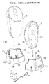
図5(A)、(B)に示すように、受信装置15は、略立方体形状であり、内部に受信アンテナ90(図6参照)、雌コネクタ91及びプリント基板回路モジュール92を有する。受信装置15は、上面から前面にかけての部分に、凹状のワイヤレスマウスセット部93を有する。このワイヤレスマウスセット部93は、ワイヤレスマウス14の後端側の部分が丁度収まって、ワイヤレスマウス14を倒れないようにして縦向きに支持する形状を有する。ワイヤレスマウスセット部93には、ワイヤレスマウス14の充電用端子37,38に対応した配置で、充電用端子94,95が露出して設けてある。
【0058】
また、受信装置15の側面には、ACアダプタ用接続端子106が設けてある。商用電源のコンセントに差し込まれているACアダプタ107より延びているケーブルの先端のコネクタ108がACアダプタ用接続端子106に接続されている。
【0059】
プリント基板回路モジュール92は、図6に示すように、ワイヤレスマウス用のマイクロコントローラユニット96、二次電池充電用電源回路97、データ受信モジュール98、及びPS/2通信用のマイクロコントローラユニット99を有する。
【0060】
データ受信モジュール98とワイヤレスマウス用のマイクロコントローラユニット96とは、バス100によって接続してある。ワイヤレスマウス用のマイクロコントローラユニット96、二次電池充電用電源回路97、及びデータ受信モジュール98は、並列に接続してあり、電圧Vccを加えられて動作する。
【0061】
データ受信モジュール98は、受信アンテナ90で受信したワイヤレスマウス14からの無線信号を処理して、これをワイヤレスマウス用のマイクロコントローラユニット96に送る。
【0062】
ワイヤレスマウス用のマイクロコントローラユニット96は、データ受信モジュール98からの信号をUSBモードの信号に処理して、これをデータライン103、104に出力する。また、マイクロコントローラユニット96は、インターフェイスがPS/2であることを検出し、これを検出した場合にライン105に信号を出力して、トランジスタTr4をオンとして、電圧VccがPS/2通信用のマイクロコントローラユニット99に加えられるようにする。
【0063】
二次電池充電用電源回路97は、電圧4.4Vを端子94,95に出力する。
【0064】
PS/2通信用のマイクロコントローラユニット99は、ワイヤレスマウス用のマイクロコントローラユニット96とバス101で接続してあり、インターフェイスがPS/2である場合に、ワイヤレスマウス用のマイクロコントローラユニット96からのデータをPS/2インターフェイス信号に変換して、これをデータライン103、104に出力する。
【0065】
なお、ワイヤレスマウス用のマイクロコントローラユニット96が、図4中のマイクロコントローラユニット73と同じく、インターフェイスがPS/2であることを検知した場合には、USB動作状態からPS/2動作状態に自動的に切り換わる構成である場合には、PS/2通信用のマイクロコントローラユニット99は不要である。
【0066】
図7はコネクタケーブル18を示す。コネクタケーブル18は、一端にUSB雄コネクタ16、他端にコネクタ17を有する。
【0067】
次に、上記構成になるワイヤレスマウスユニット10の使用態様について説明する。
【0068】
コンピュータ本体11は、背面に、USB雌コネクタを有する構成である。
(1)ワイヤレスマウス14をワイヤレスで使用する場合(図1参照)
コネクタケーブル18のUSB雄コネクタ16がコンピュータ本体11の背面のUSB雌コネクタに接続されており、コネクタケーブル18がコンピュータ本体11から延びている。コネクタケーブル18のコネクタ17が受信装置15の雌コネクタ91に接続してある。受信装置15は、コンピュータ本体11からコネクタケーブル18を通って加えられる電源電圧Vccで動作している。
【0069】
ワイヤレスマウス14は、二次電池50の出力電圧によって動作する。図4を参照するに、二次電池50の出力電圧は、昇圧回路77によって昇圧されて、LED61及び光学式センサチップ62に加えられ、LED61が発光し、オプティカルセンサ装置36が動作する。また、二次電池50の出力電圧がワイヤレスマウス用のマイクロコントローラユニット70及びデータ送信モジュール71に加えられ、これらが動作する。
【0070】
ワイヤレスマウス14の操作を行うことによって、無線信号19が送信され、受信装置15の受信アンテナ90がこの無線信号19を受信する。データ受信モジュール98が受信アンテナ90で受信したワイヤレスマウス14からの無線信号を処理して、これをワイヤレスマウス用のマイクロコントローラユニット96に送る。ワイヤレスマウス用のマイクロコントローラユニット96は、データ受信モジュール98からの信号をUSBインターフェイス信号に処理して、これをデータライン103、104に出力し、コネクタケーブル18を通ってコンピュータ本体11に送られ、CRTモニタ12の表示画面20中のカーソル21が移動される。
【0071】
太陽電池66はLED61から出る光のうち斜め上方及び上方に向かう光65bを受けて電力を出力する。この電力はオプティカルセンサ装置36、ワイヤレスマウス用のマイクロコントローラユニット70及びデータ送信モジュール71を動作させる電力を補助し、太陽電池66は補助電源として機能する。また、太陽電池66の出力電力は、二次電池50の充電にもあてられる。
(2)ワイヤレスマウス14を使用していないときの状態(図8参照)
図8に示すように、ワイヤレスマウス14を縦向きにして受信装置15の凹状のワイヤレスマウスセット部93に上方から収める。ワイヤレスマウス14は、倒れないように縦向きに支持されて保管され、且つ、充電用端子37,38が対応する充電用端子94,95と接触する。
【0072】
保管されているワイヤレスマウス14には、受信装置15の端子94,95から、端子37,38を介して4.4Vの電圧が加えられ、これによって二次電池50が充電される。これによって、保管されている間に、ワイヤレスマウス14をワイヤレスで使用したことによって消費された二次電池50の電圧が回復される。
【0073】
図4を参照するに、充電動作は、コンピュータ本体11からコネクタケーブル18を通して電力を供給されている受信装置15内の二次電池充電用電源回路97から供給される電力によって、二次電池充電制御コントローラ74によって制御されつつ行われる。即ち、二次電池50の充電は満充電の状態となるまで行われ、二次電池50が満充電の状態となると、二次電池充電制御コントローラ74からの信号によって過充電防止スイッチ回路75が開いて、充電回路76がオフとされて、二次電池50の充電が終了される。よって、二次電池50が無用に発熱することが起きない。
【0074】
なお、操作者がコンピュータ本体11の電源を遮断した後においても、二次電池50はACアダプタ107より供給されている電力によって充電され続ける。
(3)ワイヤレスマウス14をワイヤードで使用するときの状態(図9参照)
ワイヤレスマウス14をワイヤードで使用するのは、ワイヤレスマウス14の二次電池50を充電することをし忘れ、ワイヤレスマウス14を使用しようとした場合に動作しなくなった場合であり、非常時の手段であり、保険的な意味合いを有する。即ち、二次電池50の電圧が下がっており、ワイヤレスマウス14が本来のワイヤレスで使用することが出来ない場合であっても、ワイヤレスマウス14を使用することが可能となる。
【0075】
コネクタケーブル18のコネクタ17を受信装置15の雌コネクタ91から抜いて、コネクタ17をワイヤレスマウス14のコネクタ34に接続する。ワイヤレスマウス14には、コンピュータ本体11からの電源電圧Vccがコネクタケーブル18を通って、コネクタ34から加えられる。
【0076】
図4を参照するに、電源電圧VccはUSB用のマイクロコントローラユニット73に加えられ、これが動作し、ライン83、84に信号を出力する。ライン83、84へ信号が出力されることによって、トランジスタTr1、Tr2がオンとされる。
【0077】
トランジスタTr1がオンとされると、電源電圧Vccが、トランジスタTr1を通り、ライン82を通って、昇圧回路77を迂回してLED61及び光学式センサチップ62に加わり、光学式センサチップ62からの出力によってトランジスタTr3がオンとされ、LED61が発光し、オプティカルセンサ装置36が動作する。よって、ワイヤレスマウス14の操作を行うことによって、オプティカルセンサ装置36からの信号がUSB用のマイクロコントローラユニット73に供給され、ここで、処理されて、データライン80、81に送り出され、更に、コネクタケーブル18を通ってコンピュータ本体11に供給され、表示画面20中のカーソル21が移動される。
【0078】
また、トランジスタTr2がオンとされることによって、電源電圧Vccが、二次電池充電制御コントローラ74、ワイヤレスマウス用のマイクロコントローラユニット70、データ送信モジュール71等に加えられる。
【0079】
操作者がワイヤレスマウス14から手を離して、ワイヤレスマウス14がマウスパッド上に放置されて、ワイヤレスマウス14からのデータに変化が無くなった場合、即ち、オプティカルセンサ装置36からのデータが変化しなくなった場合及び操作ボタン31,32,33の操作による出力に変化がなくなった場合に、二次電池充電制御コントローラ74からの指令によって、電源電圧Vccによる二次電池50の充電が開始される。二次電池50の充電は満充電の状態となるまで行われる。
【0080】
よって、ワイヤレスマウス14をワイヤードで使用しているうちに二次電池50が充電され、ワイヤレスマウス14はワイヤレスで使用可能となる。
【0081】
次に、コンピュータ本体がUSB雌コネクタを備えていない場合について説明する。
【0082】
図10はコンピュータ本体がUSB雌コネクタを備えていない場合のワイヤレスマウスユニットの使用状態を示す図である。
【0083】
コンピュータ本体11Aは、背面にPS/2雌コネクタ110を有する。
【0084】
この場合には、USB―PS/2切換えコネクタ111を使用する。USB―PS/2切換えコネクタ111は、図10中に拡大して示すように、一端にUSB雌コネクタ112を有し、他端にPS/2雄コネクタ113を有し、USB雌コネクタ112とPS/2雄コネクタ113とが両者の間でピンの配置を変えられて背中合わせに結合されている構成である。
【0085】
コンピュータ本体11AのPS/2雌コネクタ110に、USB―PS/2変換コネクタ111のPS/2雄コネクタ113を差し込んで接続する。
【0086】
コネクタケーブル18のUSB雄コネクタ16がUSB―PS/2変換コネクタ111のUSB雌コネクタ112に接続されており、コネクタケーブル18がコンピュータ本体11Aから延びている。コネクタケーブル18のコネクタ17が受信装置15の雌コネクタ91に接続してある。
【0087】
図6に示す受信装置15内では、PS/2通信用のマイクロコントローラユニット99が動作する。
【0088】
ワイヤレスマウス14の操作を行うことによって送信アンテナ78から送信された無線信号19は、受信装置15の受信アンテナ90で受信され、データ受信モジュール98において処理され、次いで、PS/2通信用のマイクロコントローラユニット99においてPS/2通信用のデータに変換され、これがデータライン103、104に出力され、コネクタケーブル18を通ってコンピュータ本体11に送られ、CRTモニタ12の表示画面20中のカーソル21が移動される。
【0089】
ワイヤレスマウス14は、図1に示す場合と同様にワイヤレスで使用される。
【0090】
ワイヤレスマウス14の使用が終了した後には、受信装置15にセットされて、二次電池50が充電される。
【0091】
また、二次電池50が充電不足でワイヤレスマウス14がワイヤレスで使用することが出来ない場合には、コネクタ17を受信装置15から抜いて、ワイヤレスマウス14のコネクタ34に接続する。
【0092】
このときには、図4中のUSB用のマイクロコントローラユニット73が、インターフェイスがPS/2であることを検知して、USB動作状態からPS/2動作状態に自動的に切り換わる。よって、ワイヤレスマウス14からは、PS/2インターフェイス信号が送り出され、これがコネクタケーブル18を通ってコンピュータ本体11に送られ、CRTモニタ12の表示画面20中のカーソル21が移動される。
【0093】
よって、ワイヤレスマウス14は、図9に示す場合と同様に、ワイヤード状態で使用される。
【0094】
図11は、図4中、ワイヤレスマウス用のマイクロコントローラユニット70、USB用のマイクロコントローラユニット73及び二次電池充電制御コントローラ74の、ワイヤレスマウスユニット10の使用及び二次電池50の充電に関する動作のフローチャートである。
【0095】
先ず、「ワイヤレスマウス14の端子37,38が受信装置15の端子94,95に接触しているか?」を判断する(ST1)。
【0096】
この判断結果がYESの場合には、「二次電池50が満充電か?」を判断し(ST2)、この判断結果がYESの場合には、充電を行わせる(ST3)。次いで、「端子37,38の端子94,95に対する接触状態に変化があるか?」を判断し(ST5)、判断結果判断がNOの場合には、ST2に戻る。ST2の判断結果判断がNOの場合には、過充電防止スイッチ回路75を開にして充電回路をオフとする(ST4)。ST5の判断結果がYESの場合には、ST1に戻る。
【0097】
ST1の判断結果判断がNOの場合には、「コネクタ34にコネクタケーブル18のコネクタ17が接続されているか?」を判断する(ST6)。
【0098】
ST6の判断結果がNOの場合には、ワイヤレス通信を有効とし(ST7)、次いで、USB通信を無効とし(ST8)、次いで、PS/2通信を無効とする(ST9)。
【0099】
ST6の判断結果がYESの場合には、「インターフェイスはUSBか?」を判断する(ST10)。
【0100】
ST10の判断結果がYESの場合には、USB通信を有効とし(ST11)、次いで、ワイヤレス通信を無効とする(ST12)。
【0101】
ST10の判断結果がNOの場合には、PS/2通信を有効とし(ST17)、次いで、ワイヤレス通信を無効とする(ST12)。
【0102】
次いで、「オプティカルセンサ装置36からの出力及び操作ボタン31,32,33の操作による出力に変化あるか?」を判断する(ST13)。この判断結果がNOの場合には、「二次電池50が満充電か?」を判断し(ST14)、この判断結果がNOの場合には、充電を行わせる(ST15)。ST14の判断結果判断がYESの場合には、スイッチ回路75を開にして充電回路76をオフとする(ST16)。
【0103】
次に、本発明の別の実施例になるワイヤレスマウス14Aについて説明する。
【0104】
図12はワイヤレスマウス14Aを示す。ワイヤレスマウス14Aは、図2(A)にワイヤレスマウス14とは、本体30の上面に、太陽電池120が設けてある点が相違する。ワイヤレスマウス14Aは、図2(A)にワイヤレスマウス14と同様に、ワイヤレスで使用され、使用していないときには受信装置15にセットされ、また、二次電池50が消費されて電圧が低くなっている場合にはワイヤードで使用される。
【0105】
太陽電池120は、ワイヤレスマウス14Aが使用されている場合には操作者の手のひらに覆われているけれども、ワイヤレスマウス14Aが使用を中断されてマウスパッド上に放置されている場合、及び、受信装置15にセットされている場合には、太陽電池120は露出しており、外部の光を受けて、発電を行っている。この太陽電池120は、図13に示すように、二次電池50と並列に接続してあり、太陽電池120が発電した電気は、二次電池50の充電にあてられる。
【0106】
図14は、図13中、マイクロコントローラユニット70、73及び二次電池充電制御コントローラ74の、ワイヤレスマウスユニットの使用及び二次電池50の充電に関する動作のフローチャートである。
【0107】
図14のフローチャートは、図11のフローチャートに、ST20〜ST23が追加された構成である。ST9に続いて、「オプティカルセンサ装置36からの出力及び操作ボタン31,32,33の操作による出力に変化あるか?」を判断する(ST20)。この判断結果がNOの場合には、「二次電池50が満充電か?」を判断し(ST21)、この判断結果がNOの場合には、充電を行わせる(ST22)。ST21の判断結果判断がYESの場合には、スイッチ回路75を開にして充電回路76をオフとする(ST23)。
【0108】
ワイヤレス通信の手段としては、電波の他に赤外線を使用することも可能である。
【0109】
以上、本発明を実施例により説明したが、本発明は前記実施例に限定されるものではなく、本発明の範囲内で種々の変形及び改良が可能であることはいうまでもない。
【0110】
【発明の効果】
以上説明したように、請求項1の発明は、充電可能電池を備えたワイヤレスマウスと受信装置とよりなるワイヤレスマウスユニットにおいて、受信装置を、充電用端子を設けた構成としたものであるため、受信装置を充電用端子を設けた構成としたことによって、ワイヤレスマウスの充電可能電池を充電するための専用の充電器が不要とすることが出来る。
【0111】
請求項2の発明は、請求項1記載のワイヤレスマウスユニットにおいて、受信装置は、ワイヤレスマウスがセットされる形状のワイヤレスマウスセット部を有しており、充電用端子は、ワイヤレスマウスセット部内に、ワイヤレスマウスセット部にセットされたワイヤレスマウスの充電用端子と接触するように配置してある構成としたものであるため、ワイヤレスマウスを使用を終了したのちに、ワイヤレスマウスをワイヤレスマウスセット部にセットして保管することが可能となり、且つ、この保管中に充電可能電池を充電することが可能となる。よって、ワイヤレスマウスは、充電可能電池が十分に充電されている状態で使用を開始することが出来る。
【0112】
請求項3の発明は、充電可能電池を備えたワイヤレスマウスと受信装置とよりなるワイヤレスマウスユニットにおいて、一端にコンピュータのUSBコネクタに接続されるUSBコネクタを有し、他端に他端側コネクタを有するコネクタケーブルを更に有してなり、受信装置は、上記他端側コネクタが接続される受信装置側コネクタを有し、ワイヤレスマウスは、上記他端側コネクタが接続されるワイヤレスマウスコネクタと、ワイヤレスマウスコネクタからの電力によって動作するUSB用のマイクロコントローラユニットと、ワイヤレスマウスコネクタからの電力によって動作されて使用されており、該ワイヤレスマウスが放置されているときに、コンピュータからケーブルを通して供給される電力によって充電可能電池を充電させる手段とを有する構成としたものであるため、ワイヤレスマウスは他端側コネクタが接続されるワイヤレスマウスコネクタを備えているため、コネクタケーブルをワイヤレスマウスコネクタに接続することによって、ワイヤレスマウスをコンピュータからの電力によって動作させることが可能となる。よって、例えば、ワイヤレスマウスの充電可能電池を充電することをし忘れ、ワイヤレスマウスを使用しようとした場合に動作しない場合であっても、ワイヤレスマウスを使用することが出来る。
【0113】
また、ワイヤレスマウスが使用を中断されてマウスパッド上に放置されている間に充電可能電池に充電が行われ、よって、ワイヤレスマウスをワイヤードで使用している間に、充電可能電池が充電され、ワイヤレスマウスは本来のワイヤレスで使用することが可能となるようにすることが出来る。
【0114】
請求項4の発明は、充電可能電池を備えており、操作して表示画面中のカーソルを移動させるワイヤレスマウスと、コンピュータとワイヤによって接続してある受信装置とよりなるワイヤレスマウスユニットにおいて、一端にコンピュータのUSBコネクタに接続されるUSBコネクタを有し、他端に他端側コネクタを有するコネクタケーブルと、USB―PS/2変換コネクタとを更に有する構成であり、且つ、受信装置は、他端側コネクタが接続される受信装置側コネクタと、コネクタケーブルの端のUSBコネクタが、USB―PS/2変換コネクタを介してコンピュータと接続されているときには、PS/2モードに切り替えられる構成のUSB用のマイクロコントローラユニットとを有する構成としたものであるため、USBコネクタを備えていないコンピュータに対しても、ワイヤレスマウスユニットを、ワイヤレスマウスがワイヤレスの状態で使用することが出来る。
【0115】
請求項5の発明は、充電可能電池を備えており、操作して表示画面中のカーソルを移動させるワイヤレスマウスと、コンピュータとワイヤによって接続してある受信装置とよりなるワイヤレスマウスユニットにおいて、一端にコンピュータのUSBコネクタに接続されるUSBコネクタを有し、他端に他端側コネクタを有するコネクタケーブルと、USB―PS/2変換コネクタとを更に有する構成であり、且つ、ワイヤレスマウスは、他端側コネクタが接続されるワイヤレスマウスコネクタと、ワイヤレスマウスコネクタからの電力によって動作し、且つ上記コネクタケーブルの端のUSBコネクタが、USB―PS/2変換コネクタを介してコンピュータと接続されているときには、PS/2モードに切り替えられる構成のUSB用のマイクロコントローラユニットと、該ワイヤレスマウスコネクタからの電力によって動作されて使用されており、該ワイヤレスマウスが放置されているときに、コンピュータからケーブルを通して供給される電力によって充電可能電池を充電させる手段とを有する構成としたものであるため、USBコネクタを備えていないコンピュータに対しても、ワイヤレスマウスユニットを、ワイヤレスマウスがワイヤードの状態で使用することが出来る。
【0116】
また、ワイヤレスマウスが使用を中断されてマウスパッド上に放置されている間に充電可能電池に充電が行われ、よって、ワイヤレスマウスをワイヤードで使用している間に、充電可能電池が充電され、ワイヤレスマウスは本来のワイヤレスで使用することが可能となるようにすることが出来る。
【0117】
請求項6の発明は、コンピュータに接続してある受信装置にワイヤレス通信によって表示画面中のカーソルを移動させる情報を送信する機能を有するワイヤレスマウスにおいて、充電可能電池と、受信装置にセットされたときに、該受信装置の充電用端子と接続される充電用端子とを有し、受信装置にセットされた状態で、上記コンピュータからの電力によって、上記充電可能電池が充電される構成としたものであるため、ワイヤレスマウスを使用を終了したのちに、ワイヤレスマウスをワイヤレスマウスセット部にセットして保管することが可能となり、且つ、この保管中に充電可能電池を充電することが可能となる。よって、ワイヤレスマウスは、充電可能電池が十分に充電されている状態で使用を開始することが出来る。
【0118】
請求項7の発明は、請求項6のワイヤレスマウスにおいて、上面に太陽電池を有し、太陽電池が、上記充電可能電池と並列に接続してある構成としたものであるため、太陽電池が発電した電力を、ワイヤレスマウスの動作及び充電可能電池の充電に利用することが可能となる。よって、充電可能電池の消耗が抑えることが出来る。
【0119】
請求項8の発明は、請求項6のワイヤレスマウスにおいて、発光素子と発光素子より出て該ワイヤレスマウスが操作される面で反射した光を受光する光学式センサチップとよりなるオプティカルセンサ装置を有し、且つ、上記発光素子より出た光の一部を受光する内部太陽電池を有し、内部太陽電池が、上記充電可能電池と並列に接続してある構成としたものであるため、内部太陽電池が発電した電力を、ワイヤレスマウスの動作及び充電可能電池の充電に利用することが可能となる。よって、充電可能電池の消耗を抑えることが出来る。
【0120】
請求項9の発明は、コンピュータに接続してある受信装置にワイヤレス通信によって表示画面中のカーソルを移動させる情報を送信する機能を有するワイヤレスマウスにおいて、コンピュータのUSB雌コネクタに接続されて該コンピュータから延びているケーブルの端のコネクタと接続されるコネクタとを有し、コネクタからの電力によって動作するように設けてあるUSB用のマイクロコントローラユニットとを有する構成としたものであるため、ワイヤレスマウスはケーブルの端のコネクタが接続されるコネクタを備えているため、コネクタケーブルをワイヤレスマウスのコネクタに接続することによって、ワイヤレスマウスをコンピュータからの電力によって動作させることが可能となる。よって、例えば、ワイヤレスマウスの充電可能電池を充電することをし忘れ、ワイヤレスマウスを使用しようとした場合に動作しな場合であっても、ワイヤレスマウスを使用することが出来る。
【0121】
請求項10の発明は、コンピュータに接続してある受信装置にワイヤレス通信によって表示画面中のカーソルを移動させる情報を送信する機能を有するワイヤレスマウスにおいて、充電可能である電池と、コンピュータのUSB雌コネクタに接続されて該コンピュータから延びているケーブルの端のコネクタと接続されるコネクタとを有し、該コネクタからの電力によって動作するように設けてあるUSB用のマイクロコントローラユニットとを有し、ワイヤレスマウスがそのコネクタにケーブルの端のコネクタを接続されて使用されており、該ワイヤレスマウスが放置されているときに、コンピュータからケーブルを通して供給される電力によって充電可能電池が充電される構成としたものであるため、ワイヤレスマウスはケーブルの端のコネクタが接続されるコネクタを備えているため、コネクタケーブルをワイヤレスマウスのコネクタに接続することによって、ワイヤレスマウスをコンピュータからの電力によって動作させることが可能となる。よって、例えば、ワイヤレスマウスの充電可能電池を充電することをし忘れ、ワイヤレスマウスを使用しようとした場合に動作しな場合であっても、ワイヤレスマウスを使用することが出来る。
【0122】
また、ワイヤレスマウスが使用を中断されてマウスパッド上に放置されている間に充電可能電池に充電が行われ、よって、ワイヤレスマウスをワイヤードで使用している間に、充電可能電池が充電され、ワイヤレスマウスは本来のワイヤレスで使用することが可能となるようにすることが出来る。
【0123】
請求項11の発明は、コンピュータと接続されて使用され、充電可能電池及び充電用端子を有するワイヤレスマウスから送信された表示画面中のカーソルを移動させる情報を受信する受信装置において、上記ワイヤレスマウスがセットされる形状のワイヤレスマウスセット部を有し、且つ、該ワイヤレスマウスセット部に、コンピュータからの電力が供給されており、この受信装置にセットされたワイヤレスマウスの充電用端子と接続される充電用端子を有し、上記受信装置のワイヤレスマウスセット部に上記ワイヤレスマウスがセットされた状態で、上記コンピュータからの電力によって、ワイヤレスマウスの充電可能を充電する構成としたものであるため、受信装置を、使用を終了したワイヤレスマウスを保管する場所として使用することが出来、且つ、使用を終了したワイヤレスマウスの充電可能電池の充電に使用することが可能となる。よって、専用の充電器が不要となる。
【0124】
請求項12の発明は、請求項11に記載の受信装置において、コンピュータのUSBコネクタに接続されてコンピュータから延びているケーブルの端のコネクタと接続されるコネクタを有する構成としたものであるため、受信装置に接続されていたケーブルの端のコネクタを引き抜くことによって、このコネクタをワイヤレスマウスに接続することが可能となり、よって、ワイヤレスマウスを、本来のワイヤレスの他に、ワイヤードでも使用することが出来る。
【図面の簡単な説明】
【図1】本発明の一実施例になるワイヤレスマウスユニットの通常の使用状態を示す図である。
【図2】本発明の一実施例になるワイヤレスマウスを示す図である。
【図3】図2のワイヤレスマウスの内部のオプティカルセンサ装置を示す図である。
【図4】図2のワイヤレスマウスの回路図である。
【図5】本発明の一実施例になる受信装置を示す図である。
【図6】図5に示す受信装置のブロック図である。
【図7】コネクタケーブルを示す図である。
【図8】ワイヤレスマウスを使用していないときの状態を示す図である。
【図9】図2のワイヤレスマウスをワイヤードで使用するときの状態を示す図である。
【図10】コンピュータ本体がUSBコネクタを備えていない場合のワイヤレスマウスの使用状態を示す図である。
【図11】図4中、マイクロコントローラユニット70,73及びコントローラ74の充電等に関する動作のフローチャートである。
【図12】本発明の別の実施例のワイヤレスマウスを示す図である。
【図13】図12のワイヤレスマウスの回路図である。
【図14】図12中、マイクロコントローラユニット70,73及びコントローラ74の充電等に関する動作のフローチャートである。
【符号の説明】
10 ワイヤレスマウスユニット
11、11A コンピュータ本体
14、14A ワイヤレスマウス
15 受信装置
16 USB雄コネクタ
17 コネクタ
18 コネクタケーブル
34 雌コネクタ
36 オプティカルセンサ装置
37,38 充電用端子
50 二次電池
61 LED
62 光学式センサチップ
66 太陽電池
70 ワイヤレスマウス用のマイクロコントローラユニット
71 データ送信モジュール
73 USB用のマイクロコントローラユニット
74 二次電池充電制御コントローラ
75 過充電防止スイッチ回路
76 充電回路
77 昇圧回路
78 送信アンテナ
90 受信アンテナ
93 ワイヤレスマウスセット部
94,95 充電用端子
96 ワイヤレスマウス用のマイクロコントローラユニット
97 二次電池充電用電源回路
98 データ受信モジュール
99 PS/2通信用のマイクロコントローラユニット
110 PS/2雌コネクタ
111 USB−PS/2変換コネクタ
120 太陽電池[0001]
BACKGROUND OF THE INVENTION
The present invention relates to a wireless mouse unit, a wireless mouse, and a receiving device, and in particular, is connected to a wireless mouse and a computer having a function of transmitting information for moving a cursor on a display screen by wireless communication, and information from the wireless mouse. And a wireless mouse unit including the wireless mouse and the receiving device.
[0002]
In general, a wireless mouse has an advantage that there is no troublesome wire, but since it is not connected by a wire, the mouse itself needs to have a built-in power supply. As the built-in power source, a dry battery or a rechargeable secondary battery is used.
[0003]
Also, in addition to the general mouse structure in which the ball on the bottom rolls and rotates on the mouse pad when the mouse is moved, a structure using an optical sensor has recently been put into practical use. It's getting on. The type of mouse where the ball rolls on the mouse pad needs to be repaired because the ball picks up dust on the mouse pad and the dust accumulates inside the mouse while it is in use for a long time, causing the ball to rotate smoothly. turn into. In the mouse using the optical sensor device, the optical sensor device is not in contact with the mouse pad, so that there is an advantage that there is no dust problem and maintenance is not necessary. However, since a light emitting diode or the like is used, power consumption is high. Therefore, in the dry cell type wireless mouse, it is necessary to frequently replace the dry cell, which is not economical. Therefore, a secondary battery type wireless mouse is preferable. Even in this case, since the power consumption of the secondary battery is large, in order to improve usability, it is necessary to devise charging and the like.
[0004]
[Prior art]
A conventional wireless mouse with a built-in secondary battery includes a dedicated charging device as an accessory, and is set in the charging device to charge the secondary battery.
[0005]
[Problems to be solved by the invention]
For this reason, the wireless mouse unit has a charging device in addition to the wireless mouse and the receiving device, and is bulky, unusable and expensive.
[0006]
In addition, the conventional wireless mouse cannot be used while connected to a cable. For this reason, the mouse cannot be used when it is out of charge, and the wireless mouse cannot be used if the voltage of the secondary battery drops when trying to use it. I was unable to use my computer, which was inconvenient.
[0007]
Therefore, an object of the present invention is to provide a wireless mouse unit, a wireless mouse, and a receiving device that solve the above-described problems.
[0008]
[Means for Solving the Problems]
[0020]
The invention of claim 1 is a wireless mouse having a function of transmitting information for moving a cursor in a display screen by wireless communication to a receiving apparatus that is normally connected to a computer via a connector cable.
Rechargeable batteries,
A charging terminal connected to the charging terminal of the receiving device when set in the receiving device;
An optical sensor device comprising: a light emitting element; and an optical sensor chip that receives light reflected from a surface on which the wireless mouse is operated and exits from the light emitting element;
And having an internal solar cell that receives a part of the light emitted from the light emitting element,
The internal solar cell is the rechargeable batteryBoth via the booster circuit to the optical sensor deviceThe configuration is connected in parallel,
The rechargeable battery is set by the power from the computer while being set in the receiving device.Bypassing the booster circuitThe wireless mouse is configured to be charged, and the connector cable is connected in an emergency to allow the rechargeable battery to be charged.,
It is characterized by that.
[0021]
After the use of the wireless mouse is finished, the wireless mouse can be set and stored in the wireless mouse set unit, and the rechargeable battery can be charged during the storage. Therefore, the wireless mouse can be used in a state where the rechargeable battery is sufficiently charged.
[0025]
The electric power generated by the internal solar cell can be used for the operation of the wireless mouse and the charging of the rechargeable battery. Therefore, consumption of the rechargeable battery can be suppressed.
[0035]
DETAILED DESCRIPTION OF THE INVENTION
FIG. 1 shows a normal use state of a
[0036]
11 is a computer main body, 12 is a CRT monitor, and 13 is a keyboard. 14 is a wireless mouse and 15 is a receiving device. The
[0037]
By operating the
[0038]
The
[0039]
First, the
[0040]
2A and 2B show the appearance of the
[0041]
The charging
[0042]
Inside the
[0043]
FIG. 3 shows the structure of the
[0044]
[0045]
FIG. 3 shows a circuit diagram of the
[0046]
In addition to the
[0047]
The
[0048]
The power supply voltage Vcc is 4.4 to 5.25V. The rated voltage of the
[0049]
The
[0050]
The wireless
[0051]
The
[0052]
The data transmission module 71 radiates a radio wave of a signal for moving the
[0053]
The
[0054]
The secondary battery charge control controller 74 is connected in parallel with the
[0055]
The booster circuit 77 is provided between the
[0056]
Next, the receiving
[0057]
As shown in FIGS. 5A and 5B, the receiving
[0058]
An AC
[0059]
As shown in FIG. 6, the printed circuit
[0060]
The data receiving module 98 and the
[0061]
The data receiving module 98 processes the radio signal from the
[0062]
The
[0063]
The secondary battery charging
[0064]
The
[0065]
If the
[0066]
FIG. 7 shows the
[0067]
Next, a usage mode of the
[0068]
The computer
(1) When using the
The
[0069]
The
[0070]
By operating the
[0071]
The
(2) State when the
As shown in FIG. 8, the
[0072]
The stored
[0073]
Referring to FIG. 4, the charging operation is performed by the secondary battery charging control by the power supplied from the secondary battery charging
[0074]
Even after the operator shuts off the power supply of the computer
(3) State when the
The
[0075]
The
[0076]
Referring to FIG. 4, the power supply voltage Vcc is applied to the
[0077]
When the transistor Tr1 is turned on, the power supply voltage Vcc passes through the transistor Tr1, passes through the
[0078]
When the transistor Tr2 is turned on, the power supply voltage Vcc is applied to the secondary battery charge control controller 74, the
[0079]
When the operator removes his / her hand from the
[0080]
Therefore, the
[0081]
Next, a case where the computer main body is not provided with a USB female connector will be described.
[0082]
FIG. 10 is a diagram illustrating a usage state of the wireless mouse unit when the computer main body does not include the USB female connector.
[0083]
The computer
[0084]
In this case, the USB-PS / 2
[0085]
The PS / 2
[0086]
The
[0087]
In the receiving
[0088]
The
[0089]
The
[0090]
After the use of the
[0091]
If the
[0092]
At this time, the
[0093]
Therefore, the
[0094]
11 shows operations of the wireless
[0095]
First, it is determined whether the
[0096]
If the determination result is YES, it is determined whether the
[0097]
If the determination result in ST1 is NO, it is determined whether the
[0098]
If the determination result in ST6 is NO, wireless communication is enabled (ST7), then USB communication is disabled (ST8), and then PS / 2 communication is disabled (ST9).
[0099]
If the determination result in ST6 is YES, it is determined whether the interface is USB (ST10).
[0100]
If the determination result in ST10 is YES, USB communication is enabled (ST11), and then wireless communication is disabled (ST12).
[0101]
If the determination result in ST10 is NO, PS / 2 communication is enabled (ST17), and then wireless communication is disabled (ST12).
[0102]
Next, it is determined whether there is a change in the output from the
[0103]
Next, a
[0104]
FIG. 12 shows a
[0105]
When the
[0106]
FIG. 14 is a flowchart of operations related to the use of the wireless mouse unit and the charging of the
[0107]
The flowchart of FIG. 14 has a configuration in which ST20 to ST23 are added to the flowchart of FIG. Subsequent to ST9, it is determined whether or not there is a change in the output from the
[0108]
As a means for wireless communication, it is possible to use infrared rays in addition to radio waves.
[0109]
Although the present invention has been described with reference to the embodiments, it is needless to say that the present invention is not limited to the above embodiments, and various modifications and improvements can be made within the scope of the present invention.
[0110]
【The invention's effect】
As described above, the invention of claim 1 is a wireless mouse unit comprising a wireless mouse equipped with a rechargeable battery and a receiving device, wherein the receiving device is configured to have a charging terminal. Since the receiving device is provided with a charging terminal, a dedicated charger for charging the rechargeable battery of the wireless mouse can be eliminated.
[0111]
According to a second aspect of the present invention, in the wireless mouse unit according to the first aspect, the receiving device has a wireless mouse set portion in which the wireless mouse is set, and the charging terminal is in the wireless mouse set portion. Because it is configured to be in contact with the charging terminal of the wireless mouse set in the wireless mouse set part, after using the wireless mouse, set the wireless mouse in the wireless mouse set part The rechargeable battery can be charged during the storage. Therefore, the wireless mouse can be used in a state where the rechargeable battery is sufficiently charged.
[0112]
According to a third aspect of the present invention, in a wireless mouse unit comprising a wireless mouse having a rechargeable battery and a receiving device, a USB connector connected to a USB connector of a computer is provided at one end, and the other end connector is provided at the other end. The receiving device has a receiving device side connector to which the other end side connector is connected, and the wireless mouse has a wireless mouse connector to which the other end side connector is connected, and a wireless mouse. A microcontroller unit for USB that operates with power from the mouse connector and power that is operated and used with power from the wireless mouse connector and is supplied from the computer through the cable when the wireless mouse is left unattended Hand charging a rechargeable battery by Since the wireless mouse has a wireless mouse connector to which the connector on the other end is connected, connecting the connector cable to the wireless mouse connector allows the wireless mouse to receive power from the computer. Can be operated. Thus, for example, even if the user forgets to charge the rechargeable battery of the wireless mouse and does not operate when trying to use the wireless mouse, the wireless mouse can be used.
[0113]
In addition, the rechargeable battery is charged while the wireless mouse is discontinued and left on the mouse pad, so the rechargeable battery is charged while using the wireless mouse wired, The wireless mouse can be used with the original wireless.
[0114]
According to a fourth aspect of the present invention, there is provided a wireless mouse unit including a rechargeable battery and comprising a wireless mouse that is operated to move a cursor in a display screen and a receiving device connected to the computer by a wire. It has a USB connector connected to a USB connector of a computer, a connector cable having a connector on the other end on the other end, and a USB-PS / 2 conversion connector, and the receiving device has the other end The USB connector is configured to be switched to the PS / 2 mode when the receiving device side connector to which the side connector is connected and the USB connector at the end of the connector cable are connected to the computer via the USB-PS / 2 conversion connector. Because it has a configuration with a microcontroller unit, Even for a computer that does not have the data, the wireless mouse unit, wireless mouse can be used in a wireless state.
[0115]
According to a fifth aspect of the present invention, there is provided a wireless mouse unit comprising a rechargeable battery and comprising a wireless mouse that is operated to move a cursor in a display screen, and a receiving device connected to the computer by a wire. The wireless mouse has a USB connector connected to a USB connector of a computer, a connector cable having a connector on the other end on the other end, and a USB-PS / 2 conversion connector. When the USB connector at the end of the connector cable is connected to the computer via the USB-PS / 2 conversion connector, the wireless mouse connector to which the side connector is connected and the USB connector at the end of the connector cable are operated. A USB device that can be switched to PS / 2 mode. And a means for charging a rechargeable battery with power supplied from a computer through a cable when the wireless mouse is left unused. Since it has the configuration, the wireless mouse unit can be used with the wireless mouse in a wired state even for a computer that does not include a USB connector.
[0116]
In addition, the rechargeable battery is charged while the wireless mouse is discontinued and left on the mouse pad, so the rechargeable battery is charged while using the wireless mouse wired, The wireless mouse can be used with the original wireless.
[0117]
According to a sixth aspect of the present invention, in a wireless mouse having a function of transmitting information for moving a cursor on a display screen by wireless communication to a receiving apparatus connected to a computer, when the rechargeable battery is set in the receiving apparatus And a charging terminal connected to the charging terminal of the receiving device, and the rechargeable battery is charged with power from the computer in a state set in the receiving device. Therefore, after the use of the wireless mouse is finished, the wireless mouse can be set and stored in the wireless mouse set unit, and the rechargeable battery can be charged during the storage. Therefore, the wireless mouse can be used in a state where the rechargeable battery is sufficiently charged.
[0118]
The invention according to claim 7 is the wireless mouse according to claim 6, wherein the solar cell has a solar cell on the upper surface, and the solar cell is connected in parallel with the rechargeable battery. The power thus obtained can be used for the operation of the wireless mouse and the charging of the rechargeable battery. Therefore, consumption of the rechargeable battery can be suppressed.
[0119]
According to an eighth aspect of the present invention, there is provided an optical sensor device comprising: a light emitting element; and an optical sensor chip that receives light emitted from the light emitting element and reflected by a surface on which the wireless mouse is operated. And an internal solar cell that receives a part of the light emitted from the light emitting element, and the internal solar cell is connected in parallel with the rechargeable battery. The power generated by the battery can be used for the operation of the wireless mouse and the charging of the rechargeable battery. Therefore, consumption of the rechargeable battery can be suppressed.
[0120]
According to a ninth aspect of the present invention, there is provided a wireless mouse having a function of transmitting information for moving a cursor in a display screen to a receiving apparatus connected to a computer by wireless communication, and connected to a USB female connector of the computer. The wireless mouse has a connector connected to the connector at the end of the extended cable and a microcontroller unit for USB that is provided so as to be operated by electric power from the connector. Since the connector to which the connector at the end of the cable is connected is provided, the wireless mouse can be operated by power from the computer by connecting the connector cable to the connector of the wireless mouse. Therefore, for example, even if the user forgets to charge the rechargeable battery of the wireless mouse and does not operate when trying to use the wireless mouse, the wireless mouse can be used.
[0121]
According to a tenth aspect of the present invention, there is provided a wireless mouse having a function of transmitting information for moving a cursor on a display screen to a receiving apparatus connected to a computer by wireless communication, and a rechargeable battery and a USB female connector of the computer. A USB microcontroller unit that is connected to a connector at the end of a cable extending from the computer and connected to the computer, and is configured to operate by power from the connector, and wirelessly The mouse is used with its connector connected to the connector at the end of the cable, and when the wireless mouse is left unattended, the rechargeable battery is charged by the power supplied from the computer through the cable. So the wireless mouse is at the end of the cable. Since connector is a connector to be connected, by connecting the connector cable to the connector of the wireless mouse, it is possible to operate by the power of the wireless mouse from the computer. Therefore, for example, even if the user forgets to charge the rechargeable battery of the wireless mouse and does not operate when trying to use the wireless mouse, the wireless mouse can be used.
[0122]
In addition, the rechargeable battery is charged while the wireless mouse is discontinued and left on the mouse pad, so the rechargeable battery is charged while using the wireless mouse wired, The wireless mouse can be used with the original wireless.
[0123]
The invention according to
[0124]
The invention of
[Brief description of the drawings]
FIG. 1 is a diagram showing a normal use state of a wireless mouse unit according to an embodiment of the present invention.
FIG. 2 is a diagram showing a wireless mouse according to an embodiment of the present invention.
FIG. 3 is a diagram showing an optical sensor device inside the wireless mouse of FIG. 2;
4 is a circuit diagram of the wireless mouse of FIG. 2. FIG.
FIG. 5 is a diagram illustrating a receiving apparatus according to an embodiment of the present invention.
6 is a block diagram of the receiving apparatus shown in FIG.
FIG. 7 is a view showing a connector cable.
FIG. 8 is a diagram showing a state when a wireless mouse is not used.
FIG. 9 is a diagram showing a state when the wireless mouse of FIG. 2 is used in a wired manner.
FIG. 10 is a diagram illustrating a use state of the wireless mouse when the computer main body does not include a USB connector.
11 is a flowchart of operations related to charging and the like of the
FIG. 12 shows a wireless mouse according to another embodiment of the present invention.
13 is a circuit diagram of the wireless mouse in FIG. 12. FIG.
14 is a flowchart of operations related to charging and the like of the
[Explanation of symbols]
10 Wireless mouse unit
11, 11A computer body
14, 14A Wireless mouse
15 Receiver
16 USB male connector
17 Connector
18 Connector cable
34 Female connector
36 Optical sensor device
37,38 Charging terminal
50 Secondary battery
61 LED
62 Optical sensor chip
66 Solar cell
70 Microcontroller unit for wireless mouse
71 Data transmission module
73 Microcontroller unit for USB
74 Secondary battery charge control controller
75 Overcharge prevention switch circuit
76 Charging circuit
77 Booster circuit
78 Transmitting antenna
90 Receiving antenna
93 Wireless mouse set
94,95 Charging terminal
96 Microcontroller unit for wireless mouse
97 Power supply circuit for secondary battery charging
98 Data receiving module
99 Microcontroller unit for PS / 2 communication
110 PS / 2 female connector
111 USB-PS / 2 conversion connector
120 solar cell
Claims (1)
充電可能電池と、
上記受信装置にセットされたときに、該受信装置の充電用端子と接続される充電用端子とを有し、
発光素子と該発光素子より出て該ワイヤレスマウスが操作される面で反射した光を受光する光学式センサチップとよりなるオプティカルセンサ装置を有し、
且つ、上記発光素子より出た光の一部を受光する内部太陽電池を有し、
該内部太陽電池が、上記充電可能電池とともに前記オプティカルセンサ装置に昇圧回路を介して並列に接続してある構成とし、
上記受信装置にセットされた状態で、上記コンピュータからの電力によって、上記充電可能電池が前記昇圧回路を迂回して充電される構成とし、前記ワイヤレスマウスは非常時に前記コネクタケーブルが接続され上記充電可能電池が充電可能とされる構成とし、
たことを特徴としたワイヤレスマウス。In a wireless mouse having a function of transmitting information for moving a cursor in a display screen by wireless communication to a receiving apparatus that is normally connected to a computer via a connector cable,
Rechargeable batteries,
A charging terminal connected to the charging terminal of the receiving device when set in the receiving device;
An optical sensor device comprising: a light emitting element; and an optical sensor chip that receives light reflected from a surface on which the wireless mouse is operated and exits from the light emitting element;
And having an internal solar cell that receives a part of the light emitted from the light emitting element,
Internal solar cell, a structure which is connected in parallel via a booster circuit to both the optical sensor device and the rechargeable battery,
The rechargeable battery is configured to be charged by bypassing the booster circuit with the power from the computer while being set in the receiving device, and the wireless mouse can be charged by the connector cable being connected in an emergency. The battery is configured to be rechargeable ,
Wireless mouse characterized by that.
Priority Applications (2)
| Application Number | Priority Date | Filing Date | Title |
|---|---|---|---|
| JP2000351459A JP4689812B2 (en) | 2000-11-17 | 2000-11-17 | Wireless mouse |
| US09/866,648 US6801967B2 (en) | 2000-11-17 | 2001-05-30 | Wireless mouse unit, wireless mouse and receiver |
Applications Claiming Priority (1)
| Application Number | Priority Date | Filing Date | Title |
|---|---|---|---|
| JP2000351459A JP4689812B2 (en) | 2000-11-17 | 2000-11-17 | Wireless mouse |
Publications (3)
| Publication Number | Publication Date |
|---|---|
| JP2002157085A JP2002157085A (en) | 2002-05-31 |
| JP2002157085A5 JP2002157085A5 (en) | 2008-02-21 |
| JP4689812B2 true JP4689812B2 (en) | 2011-05-25 |
Family
ID=18824519
Family Applications (1)
| Application Number | Title | Priority Date | Filing Date |
|---|---|---|---|
| JP2000351459A Expired - Fee Related JP4689812B2 (en) | 2000-11-17 | 2000-11-17 | Wireless mouse |
Country Status (2)
| Country | Link |
|---|---|
| US (1) | US6801967B2 (en) |
| JP (1) | JP4689812B2 (en) |
Families Citing this family (99)
| Publication number | Priority date | Publication date | Assignee | Title |
|---|---|---|---|---|
| KR100399637B1 (en) * | 2000-12-21 | 2003-09-29 | 삼성전기주식회사 | Optical mouse |
| KR100399635B1 (en) * | 2000-12-21 | 2003-09-29 | 삼성전기주식회사 | Optical mouse |
| DE20112178U1 (en) * | 2000-12-29 | 2002-01-10 | Chic Technology Corp | Improved structure of a wireless mouse system |
| TW535343B (en) * | 2001-02-23 | 2003-06-01 | Chic Technology Corp | Charging device of wireless mouse |
| JP4588921B2 (en) * | 2001-05-21 | 2010-12-01 | 富士通コンポーネント株式会社 | Input device |
| US20030076296A1 (en) * | 2001-10-22 | 2003-04-24 | Kolybaba Derek J. | Computer mouse |
| US20030098850A1 (en) * | 2001-11-27 | 2003-05-29 | Yen Jzuhsiang | Multi-recharging models for wireless computer mouse |
| SE0104110D0 (en) * | 2001-12-06 | 2001-12-06 | Digityper Ab | Pointing Device |
| US20030107552A1 (en) * | 2001-12-11 | 2003-06-12 | Koninklijke Philips Electronics N.V. | Computer mouse with dual functionality |
| US7392068B2 (en) * | 2002-03-01 | 2008-06-24 | Mobilewise | Alternative wirefree mobile device power supply method and system with free positioning |
| US6913477B2 (en) * | 2002-03-01 | 2005-07-05 | Mobilewise, Inc. | Wirefree mobile device power supply method & system with free positioning |
| US20030193476A1 (en) * | 2002-04-11 | 2003-10-16 | Ho-Lung Lu | Structure of rechargeable wireless mouse |
| US8570378B2 (en) | 2002-07-27 | 2013-10-29 | Sony Computer Entertainment Inc. | Method and apparatus for tracking three-dimensional movements of an object using a depth sensing camera |
| US8313380B2 (en) | 2002-07-27 | 2012-11-20 | Sony Computer Entertainment America Llc | Scheme for translating movements of a hand-held controller into inputs for a system |
| US20060282873A1 (en) * | 2002-07-27 | 2006-12-14 | Sony Computer Entertainment Inc. | Hand-held controller having detectable elements for tracking purposes |
| US9393487B2 (en) | 2002-07-27 | 2016-07-19 | Sony Interactive Entertainment Inc. | Method for mapping movements of a hand-held controller to game commands |
| US7253804B2 (en) * | 2002-09-12 | 2007-08-07 | Logitech Europe S.A. | Input device with integrated key plate and integrated side grips |
| TW560653U (en) * | 2002-11-13 | 2003-11-01 | Paten Wireless Technology Inc | Wireless input device to accommodate receiver |
| TW595782U (en) * | 2002-12-13 | 2004-06-21 | Kye Systems Corp | Wireless pointer device with forcible power-off function |
| US20080174553A1 (en) * | 2002-12-19 | 2008-07-24 | Anders Trell Trust | Computer Device |
| US20040142600A1 (en) * | 2003-01-21 | 2004-07-22 | Metz Kristofer Erik | Docking station and method of operation |
| US7525291B1 (en) | 2003-01-21 | 2009-04-28 | Microsemi Corporation | Linearly regulated battery charger |
| JP3100452U (en) * | 2003-01-29 | 2004-05-20 | 派登科技股▲ふん▼有限公司 | Receiver that can accommodate wireless input device |
| US7791319B2 (en) * | 2003-02-21 | 2010-09-07 | Research In Motion Limited | Circuit and method of operation for an electrical power supply |
| TW200416524A (en) * | 2003-02-26 | 2004-09-01 | Cellink Company Ltd | Power saving method of wireless input equipment and mechanism thereof |
| KR20040076776A (en) * | 2003-02-26 | 2004-09-03 | 김효덕 | Mouse device having function of charging a mobile-phone and recording and playing a receiving data |
| TWI225982B (en) * | 2003-03-18 | 2005-01-01 | Jeng-Shiung Chen | Power shutdown method of wireless peripheral device |
| US20050001818A1 (en) * | 2003-07-02 | 2005-01-06 | Unity Opto Technology Co., Ltd. | Optic mouse |
| US20050096086A1 (en) * | 2003-10-31 | 2005-05-05 | Jaalaa, Inc. | Computer interface with both wired and wireless links |
| US7200765B2 (en) * | 2004-01-12 | 2007-04-03 | Hewlett-Packard Development Company, L.P. | Docking station for a wireless mouse with control of a computer |
| TWI237201B (en) * | 2004-02-03 | 2005-08-01 | Benq Corp | Signal input apparatus |
| US7620915B2 (en) | 2004-02-13 | 2009-11-17 | Ludwig Lester F | Electronic document editing employing multiple cursors |
| CN1303511C (en) * | 2004-02-13 | 2007-03-07 | 明基电通股份有限公司 | Signal input unit |
| TW200530896A (en) * | 2004-03-10 | 2005-09-16 | Cellink Company Ltd | Input device with charging structure |
| JP2005346661A (en) * | 2004-06-07 | 2005-12-15 | Kg Mark Co Ltd | Information input device |
| US20060007147A1 (en) * | 2004-07-06 | 2006-01-12 | Cruise Lee | Wireless mouse with multiple charging modes |
| CN100349113C (en) * | 2004-07-15 | 2007-11-14 | 卢贺隆 | Method for detecting wireless mouse to receive mobile information using mainframe |
| TWM266618U (en) * | 2004-07-19 | 2005-06-01 | Behavior Tech Computer Corp | Multiple output connection head with wireless data collection capability |
| TWM273770U (en) * | 2004-07-19 | 2005-08-21 | Behavior Tech Computer Corp | Wireless input device having low-voltage alert function |
| US20060274037A1 (en) * | 2005-06-06 | 2006-12-07 | Stewart Sheila K | Onboard pointer system |
| JP2006119893A (en) * | 2004-10-21 | 2006-05-11 | Fujitsu Component Ltd | Input device |
| WO2006048948A1 (en) * | 2004-11-05 | 2006-05-11 | Ippey Hirano | Coordinate pointing system and method |
| JPWO2006049275A1 (en) * | 2004-11-05 | 2008-05-29 | 一平 平野 | Coordinate indicating system and method |
| US20060097120A1 (en) * | 2004-11-08 | 2006-05-11 | Yuan-Jung Chang | Charge cradle and mouse in combination |
| US20060172801A1 (en) * | 2005-01-31 | 2006-08-03 | Saied Hussaini | Video game controller with rechargeable battery system |
| US20060197755A1 (en) * | 2005-03-02 | 2006-09-07 | Bawany Muhammad A | Computer stylus cable system and method |
| US7336259B2 (en) * | 2005-04-11 | 2008-02-26 | Kye Systems Corp. | Rechargeable wireless input device |
| US20060250362A1 (en) * | 2005-05-09 | 2006-11-09 | Areson Technology Corp. | Input device capable of using cabled mouse and wireless mouse |
| TWM276276U (en) * | 2005-05-17 | 2005-09-21 | Yuan-Rung Jang | Mouse charger with wire collecting function |
| US20060278716A1 (en) * | 2005-05-31 | 2006-12-14 | Semiconductor Energy Laboratory Co., Ltd. | Input device and input system |
| TW200707204A (en) * | 2005-08-02 | 2007-02-16 | Pixart Imaging Inc | Method and apparatus for exchanging signals with a computer system through wired and wireless communication in an input device of the computer system |
| US7579809B2 (en) * | 2005-08-04 | 2009-08-25 | Staccato Communications, Inc. | Rechargeable wireless adapters |
| JP2007097330A (en) * | 2005-09-29 | 2007-04-12 | Kyocera Corp | Charger and terminal apparatus |
| US20070096938A1 (en) * | 2005-10-31 | 2007-05-03 | Emmanuel Enrique Lopez | System and method for adaptation of wireless remote controls |
| TW200719559A (en) * | 2005-11-07 | 2007-05-16 | Su-Miao Liu | Charging device and method for self-propelling-type mouse |
| TWI312958B (en) * | 2005-12-09 | 2009-08-01 | Primax Electronics Ltd | Wireless cursor control device |
| TW200722968A (en) * | 2005-12-14 | 2007-06-16 | Kye Systems Corp | Wireless computer peripheral device and its power supply method |
| US20070139378A1 (en) * | 2005-12-16 | 2007-06-21 | Siebert Benjamine J | Wireless computer mouse and presenter having text capability |
| TWI316198B (en) * | 2006-01-10 | 2009-10-21 | Primax Electronics Ltd | Wireless cursor control device |
| US20070164999A1 (en) * | 2006-01-19 | 2007-07-19 | Gruhlke Russell W | Optical navigation module and lens having large depth of field therefore |
| JP2007257394A (en) * | 2006-03-24 | 2007-10-04 | Meidensha Corp | Input mechanism for notebook computer |
| US20070230962A1 (en) * | 2006-03-29 | 2007-10-04 | Tim Simon, Inc. | Device Recognition Method |
| US8643599B2 (en) * | 2006-06-27 | 2014-02-04 | Microsoft Corporation | Washable mouse |
| USRE48417E1 (en) | 2006-09-28 | 2021-02-02 | Sony Interactive Entertainment Inc. | Object direction using video input combined with tilt angle information |
| US8781151B2 (en) | 2006-09-28 | 2014-07-15 | Sony Computer Entertainment Inc. | Object detection using video input combined with tilt angle information |
| JP4697116B2 (en) * | 2006-10-06 | 2011-06-08 | 株式会社安川電機 | Automatic machine system |
| US20080136366A1 (en) * | 2006-12-12 | 2008-06-12 | Tung-Chi Lee | Charging System for Wireless Mouse and Charging Method Thereof |
| TWI373185B (en) * | 2006-12-21 | 2012-09-21 | Wistron Corp | Power supply system and related power management method for a wireless control device |
| JP4843514B2 (en) * | 2007-01-30 | 2011-12-21 | 株式会社東芝 | Wireless transmission device |
| JP5015658B2 (en) * | 2007-05-23 | 2012-08-29 | 泰章 岩井 | Pointing device and computer |
| US20080305758A1 (en) * | 2007-06-05 | 2008-12-11 | Hatch Thomas W | Wireless computer mouse receiver |
| US20080316063A1 (en) * | 2007-06-21 | 2008-12-25 | Farzin Yassini | Integrated Keyboard With Personal Computer |
| TWM335735U (en) * | 2007-07-16 | 2008-07-01 | Wei Xu | Wireless mouse for controlling portable wireless radio set |
| CN101354616A (en) * | 2007-07-27 | 2009-01-28 | 深圳富泰宏精密工业有限公司 | Optoelectronic mouse |
| EP2075667A1 (en) | 2007-12-21 | 2009-07-01 | Thomson Licensing | System comprising a wireless user operable device and a link device having charge storage means |
| TWI360066B (en) * | 2008-01-18 | 2012-03-11 | Primax Electronics Ltd | Solar energy mouse |
| US8466774B2 (en) * | 2008-05-08 | 2013-06-18 | Secured Mobility, Llc | Remote keyless entry transmitter |
| EP2128739A1 (en) * | 2008-05-29 | 2009-12-02 | EM Microelectronic-Marin SA | Optical movement detection device |
| TW201011604A (en) * | 2008-09-12 | 2010-03-16 | Holtek Semiconductor Inc | Power saving apparatus and method for wireless mouse |
| WO2010042889A1 (en) * | 2008-10-09 | 2010-04-15 | Belkin International, Inc. | Pointing device with securing mechanism and method of providing the same |
| US20100220057A1 (en) * | 2009-02-27 | 2010-09-02 | Carder Mark D | Finger operated computer mouse |
| CN101859197A (en) * | 2009-04-13 | 2010-10-13 | 鸿富锦精密工业(深圳)有限公司 | Computer system and mouse block thereof |
| TWM388038U (en) * | 2009-11-27 | 2010-09-01 | Imu Solutions Inc | Mouse device and air mouse device having the same shell structure |
| WO2012037717A1 (en) * | 2010-09-20 | 2012-03-29 | Mediatek Singapore Pte. Ltd. | Rendering apparatuses, display system and methods for rendering multimedia data objects with a function to avoid eye fatigue |
| TW201227420A (en) * | 2010-12-29 | 2012-07-01 | Giga Byte Tech Co Ltd | Wireless mouse and charging system using the same |
| GB2502087A (en) * | 2012-05-16 | 2013-11-20 | St Microelectronics Res & Dev | Gesture recognition |
| TW201409277A (en) * | 2012-08-21 | 2014-03-01 | Hon Hai Prec Ind Co Ltd | Input system and method |
| US8850093B2 (en) * | 2013-01-25 | 2014-09-30 | Dexin Corporation | Mouse with a replaceable sensing unit |
| US10115255B2 (en) | 2013-02-07 | 2018-10-30 | Ikeyless, Llc | Method and apparatus for implementing multi-vendor rolling code keyless entry systems |
| US9454860B2 (en) | 2013-03-15 | 2016-09-27 | Secured Mobility, Llc | Integrated immobilizer fob pairing |
| US9384612B2 (en) | 2013-03-15 | 2016-07-05 | Secured Mobility, Llc | Distributing captured codes |
| US9286743B2 (en) | 2013-03-15 | 2016-03-15 | Secured Mobility, Llc | Key storage and retrieval |
| TWI716377B (en) * | 2016-01-27 | 2021-01-21 | 原相科技股份有限公司 | Self-powered optical mouse device and operating method thereof |
| TWI626526B (en) * | 2016-04-22 | 2018-06-11 | Susa Inc | Mouse |
| WO2018051672A1 (en) * | 2016-09-16 | 2018-03-22 | 株式会社 日立ハイテクノロジーズ | Automated analyzer, automated analysis system, and method for displaying reagent list |
| JP6285604B2 (en) * | 2017-06-23 | 2018-02-28 | 晃輝 平山 | Input device |
| US10928934B1 (en) | 2020-01-08 | 2021-02-23 | Dell Products L.P. | Rock and slide wireless dongle |
| US11870511B2 (en) * | 2021-03-18 | 2024-01-09 | Nxp B.V. | Near-field interface device |
| TWM619749U (en) * | 2021-09-01 | 2021-11-11 | 微星科技股份有限公司 | Input device |
Citations (5)
| Publication number | Priority date | Publication date | Assignee | Title |
|---|---|---|---|---|
| JPH1023113A (en) * | 1996-07-05 | 1998-01-23 | Mitsubishi Electric Corp | Communication device and its charging device |
| JPH10260781A (en) * | 1997-03-19 | 1998-09-29 | Hudson Soft Co Ltd | Wireless mouse |
| JPH10301708A (en) * | 1997-04-30 | 1998-11-13 | Hosiden Corp | Wireless/wired compatible mouse |
| JPH11110130A (en) * | 1997-09-30 | 1999-04-23 | Mitsumi Electric Co Ltd | Wireless mouse |
| JP2000242423A (en) * | 1999-02-22 | 2000-09-08 | Funai Electric Co Ltd | Cordless mouse |
Family Cites Families (7)
| Publication number | Priority date | Publication date | Assignee | Title |
|---|---|---|---|---|
| WO1995014286A1 (en) * | 1993-11-17 | 1995-05-26 | Microsoft Corporation | Wireless pen computer input system |
| KR100229602B1 (en) * | 1997-04-12 | 1999-11-15 | 윤종용 | Wire/wireless input apparatus with pointing device and computer system for use with the same |
| KR100259264B1 (en) * | 1997-10-02 | 2000-06-15 | 윤종용 | Computer system |
| US6211861B1 (en) * | 1998-06-23 | 2001-04-03 | Immersion Corporation | Tactile mouse device |
| US6392671B1 (en) * | 1998-10-27 | 2002-05-21 | Lawrence F. Glaser | Computer pointing device having theme identification means |
| US6255800B1 (en) * | 2000-01-03 | 2001-07-03 | Texas Instruments Incorporated | Bluetooth enabled mobile device charging cradle and system |
| US6476795B1 (en) * | 2000-01-20 | 2002-11-05 | Hewlett-Packard Company | Mouse recharging module |
-
2000
- 2000-11-17 JP JP2000351459A patent/JP4689812B2/en not_active Expired - Fee Related
-
2001
- 2001-05-30 US US09/866,648 patent/US6801967B2/en not_active Expired - Fee Related
Patent Citations (5)
| Publication number | Priority date | Publication date | Assignee | Title |
|---|---|---|---|---|
| JPH1023113A (en) * | 1996-07-05 | 1998-01-23 | Mitsubishi Electric Corp | Communication device and its charging device |
| JPH10260781A (en) * | 1997-03-19 | 1998-09-29 | Hudson Soft Co Ltd | Wireless mouse |
| JPH10301708A (en) * | 1997-04-30 | 1998-11-13 | Hosiden Corp | Wireless/wired compatible mouse |
| JPH11110130A (en) * | 1997-09-30 | 1999-04-23 | Mitsumi Electric Co Ltd | Wireless mouse |
| JP2000242423A (en) * | 1999-02-22 | 2000-09-08 | Funai Electric Co Ltd | Cordless mouse |
Also Published As
| Publication number | Publication date |
|---|---|
| JP2002157085A (en) | 2002-05-31 |
| US20020061739A1 (en) | 2002-05-23 |
| US6801967B2 (en) | 2004-10-05 |
Similar Documents
| Publication | Publication Date | Title |
|---|---|---|
| JP4689812B2 (en) | Wireless mouse | |
| JP5180920B2 (en) | Wireless control power saving outlet, wireless power detection controller and wireless control power saving device combining them together | |
| US8139032B2 (en) | Power-saving computer mouse | |
| US7944170B2 (en) | Wireless transmission device | |
| US7505252B2 (en) | Notebook computer | |
| US20090027342A1 (en) | Optical mouse | |
| JP2001117676A (en) | Information processor equipped with wireless device | |
| US7106302B2 (en) | Wireless pointing device with forced power-off function | |
| US20100090661A1 (en) | Automatic mouse charging system | |
| US20170262678A1 (en) | Wireless barcode scanning apparatus and wireless barcode scanning system including the same | |
| WO2011160343A1 (en) | Method for controlling illumination device, illumination device and mobile terminal | |
| WO2009014573A1 (en) | Power adapter | |
| CN108415585A (en) | A kind of keyboard external equipment | |
| CN2872466Y (en) | Rocking bar unit | |
| CN201556126U (en) | Notebook computer with built-in separate keyboard | |
| US7305224B2 (en) | Power saving wireless mouse having receiver receptacle | |
| CN101266526A (en) | Wireless mouse | |
| US8711096B1 (en) | Dual protocol input device | |
| JP2006004261A (en) | Portable information terminal, cradle device for portable information terminal, and information terminal system | |
| US20060202959A1 (en) | Rechargeable mouse holder | |
| CN211404912U (en) | Socket with emergency lighting function | |
| JPH10108386A (en) | Charging method and system by optical communication | |
| JP2531341Y2 (en) | Wireless remote control device in sanitary washing device | |
| JP3244985U (en) | health monitoring device | |
| CN219436684U (en) | Charging assembly and oral cavity scanner |
Legal Events
| Date | Code | Title | Description |
|---|---|---|---|
| A711 | Notification of change in applicant |
Free format text: JAPANESE INTERMEDIATE CODE: A712 Effective date: 20031125 |
|
| A621 | Written request for application examination |
Free format text: JAPANESE INTERMEDIATE CODE: A621 Effective date: 20071015 |
|
| A521 | Request for written amendment filed |
Free format text: JAPANESE INTERMEDIATE CODE: A523 Effective date: 20080104 |
|
| A977 | Report on retrieval |
Free format text: JAPANESE INTERMEDIATE CODE: A971007 Effective date: 20091005 |
|
| A131 | Notification of reasons for refusal |
Free format text: JAPANESE INTERMEDIATE CODE: A131 Effective date: 20100427 |
|
| A521 | Request for written amendment filed |
Free format text: JAPANESE INTERMEDIATE CODE: A523 Effective date: 20100525 |
|
| A02 | Decision of refusal |
Free format text: JAPANESE INTERMEDIATE CODE: A02 Effective date: 20101124 |
|
| A521 | Request for written amendment filed |
Free format text: JAPANESE INTERMEDIATE CODE: A523 Effective date: 20110112 |
|
| A911 | Transfer to examiner for re-examination before appeal (zenchi) |
Free format text: JAPANESE INTERMEDIATE CODE: A911 Effective date: 20110124 |
|
| TRDD | Decision of grant or rejection written | ||
| A01 | Written decision to grant a patent or to grant a registration (utility model) |
Free format text: JAPANESE INTERMEDIATE CODE: A01 Effective date: 20110215 |
|
| A01 | Written decision to grant a patent or to grant a registration (utility model) |
Free format text: JAPANESE INTERMEDIATE CODE: A01 |
|
| A61 | First payment of annual fees (during grant procedure) |
Free format text: JAPANESE INTERMEDIATE CODE: A61 Effective date: 20110217 |
|
| R150 | Certificate of patent or registration of utility model |
Free format text: JAPANESE INTERMEDIATE CODE: R150 |
|
| FPAY | Renewal fee payment (event date is renewal date of database) |
Free format text: PAYMENT UNTIL: 20140225 Year of fee payment: 3 |
|
| LAPS | Cancellation because of no payment of annual fees |