JP4688180B2 - Base case for gaming machines - Google Patents
Base case for gaming machines Download PDFInfo
- Publication number
- JP4688180B2 JP4688180B2 JP2009184595A JP2009184595A JP4688180B2 JP 4688180 B2 JP4688180 B2 JP 4688180B2 JP 2009184595 A JP2009184595 A JP 2009184595A JP 2009184595 A JP2009184595 A JP 2009184595A JP 4688180 B2 JP4688180 B2 JP 4688180B2
- Authority
- JP
- Japan
- Prior art keywords
- case
- base
- fixed
- fixing
- cover
- Prior art date
- Legal status (The legal status is an assumption and is not a legal conclusion. Google has not performed a legal analysis and makes no representation as to the accuracy of the status listed.)
- Expired - Fee Related
Links
Images


Description
この発明は、パチンコ機やスロットマシンなどの遊技機に用いられる遊技機用の制御基盤を収納するための遊技機用の基盤ケースに関するものである。 The present invention relates to a base case for a gaming machine for storing a control base for a gaming machine used in a gaming machine such as a pachinko machine or a slot machine.
従来、この種の遊技機用の基盤ケースとしては、パチンコ球やメダルの衝突による破損を防止するため、遊技を制御するためのプログラムを記憶したROMなどを有する制御基盤を、遊技機に固定されるケース本体と前記ケース本体を覆うケースカバーとからなる基盤ケースの内部に収納していた。
一般に、パチンコ機やスロットマシンなどの遊技機は、遊技を制御するためのプログラムを記憶したROMなどを有する制御基盤にもとづいて、入賞確率、賞球や払出メダルの枚数などの遊技動作が制御されている。そして、このROMに記憶されたプログラムの内容如何が、遊技者の利益や遊技機設置店の利益を大きく左右している。そこで、このROMに記憶されたプログラムは、遊技内容が遊技者の射幸心を徒に煽らない程度のものになるように、遊技機メーカーが調製を行ったものが用いられている。
Conventionally, as a base case for this type of gaming machine, a control base having a ROM or the like storing a program for controlling a game is fixed to the gaming machine in order to prevent damage caused by a collision of a pachinko ball or a medal. And a case cover that covers the case body.
In general, gaming machines such as pachinko machines and slot machines control game operations such as winning probabilities, the number of winning balls and payout medals based on a control board having a ROM that stores a program for controlling games. ing. The contents of the program stored in the ROM greatly influence the profit of the player and the profit of the game machine store. Therefore, the program stored in the ROM is one prepared by a gaming machine manufacturer so that the game content is such that the game content does not detract from the player's happiness.
また、メーカーが当初意図していた遊技内容から著しく遊離した遊技内容で遊技者の射幸心を著しく煽るために、遊技店へ遊技機を設置した後に、制御基盤に取り付けられた正規のROMを不正に改造したROMに交換してしまう不正行為が後を絶たない。この不正行為を防止するため、みだりにケースカバーを開放しないように、ケースカバーをケース本体にネジ止めによって固定し、さらには、正規のROMと外観上見分けがつかない不正に改造されたROMに交換されてしまわないよう、ケースカバーを開放した事実が一目瞭然になるよう、ケース本体とケースカバーとの間の所定の位置にシールを張り、シールがはがされていることで、ケースカバーが開放された事実が分かるようにしていた。 In addition, after installing a gaming machine at a gaming store, the legitimate ROM attached to the control board is illegally used in order to remarkably increase the player's gambling with gaming content that is significantly separated from the gaming content originally intended by the manufacturer. There is no end to fraudulent acts of replacing the ROM with a modified ROM. In order to prevent this illegal act, the case cover is fixed to the case body with screws so that the case cover is not opened unnecessarily, and it is also replaced with an illegally modified ROM that is indistinguishable from the regular ROM. In order not to be damaged, the case cover is opened by sticking a seal at a predetermined position between the case body and the case cover so that the fact that the case cover has been opened becomes clear at a glance. I was trying to understand the facts.
しかし、上記した従来の遊技機用の基盤ケースでは、ケースカバーは、ケース本体に対して、単にネジ止めによって固定されているだけなので、ネジをドライバーなどの工具で取り外し、シールを巧妙にはがして、ROMを交換するなどの不正改造を行ったのちに、ケースカバーを再びネジ止め固定し、シールを元通り貼り付けてしまうような、巧妙な不正行為が依然として行われてしまうといった問題点があった。 However, in the above-mentioned conventional base case for gaming machines, the case cover is simply fixed to the case body by screwing, so remove the screw with a tool such as a screwdriver and skillfully remove the seal. After performing unauthorized modifications such as replacing the ROM, the case cover is still screwed and fixed, and the clever fraud is still performed, such as pasting the seal back. It was.
この巧妙な不正行為を防止するためには、基盤ケースの構造を、ケースカバーを一度閉めてしまえば、基盤ケースを破壊しない限り、2度とケースカバーを開放することができないようにしてしまうことも考えられるが、遊技店に設置された遊技機の制御基盤などが正規のものであるか否かを、遊技店に設置した状態で検査する場合もあり、この場合に、基盤ケースを一度破壊してしまうと、以降は基盤ケースを閉止状態に保つことができず、以降の不正改造を有効に防止できなくなってしまうという問題点があった。 In order to prevent this skillful fraud, once the case cover is closed, the case cover cannot be opened again unless the case is destroyed. However, in some cases, it is possible to inspect whether the control base of the gaming machine installed at the amusement store is legitimate or not in the state where it is installed at the amusement store. In this case, the base case is once destroyed. If it does so, after that, the base case could not be kept closed, and there was a problem that it would not be possible to effectively prevent subsequent unauthorized modification.
また、基盤ケースを新しいものに交換する方法も考慮されるが、検査が複数回にわたる場合には、手間やコストがかかりすぎて現実的ではないといった問題点があった。
そこで、請求項1記載の遊技機用の基盤ケースは、上記した従来の技術の有する問題点に鑑みてなされたものであり、その目的とするところは、簡易な構造で、固定部の破断部を破断する以外に、基盤ケースを遊技機から離脱することのできないようにして、基盤ケース離脱した痕跡が必ず残るようにすることによって、制御基盤の不正な改造を未然に防止することができるとともに、検査などにおいては、基盤ケースを容易に離脱することができ、再び基盤の不正改造が不可能なように基盤ケースを遊技機に固定することのできる遊技機用の基盤ケースを提供しようとするものである。
In addition, although a method of replacing the base case with a new one is also considered, there has been a problem that it is not practical because it takes too much time and cost when the inspection is performed a plurality of times.
Accordingly, the base case for a gaming machine according to claim 1 is made in view of the above-described problems of the prior art, and the object is to have a simple structure and a fracture portion of the fixed portion. In addition to breaking the board, the base case cannot be removed from the gaming machine, and by making sure that the base case has been removed, unauthorized modification of the control base can be prevented in advance. In the inspection, etc., we try to provide a base case for gaming machines that can be easily detached from the base case and can be fixed to the gaming machine so that the base cannot be illegally modified again. Is.
(特徴点)
本発明は、上記した目的を達成するためのものであり、以下にその内容を図面に示した発明の実施の形態の一例を用いて説明する。
なお、カッコ内の符号は、発明の実施の形態において用いた符号を示すが、本発明の技術的範囲を限定するものではない。
(Feature point)
The present invention is for achieving the above-described object, and the contents thereof will be described below by using an example of the embodiment of the invention shown in the drawings.
In addition, although the code | symbol in parenthesis shows the code | symbol used in embodiment of invention, it does not limit the technical scope of this invention.
(請求項1)
請求項1記載の遊技機用の基盤ケースは、遊技機の制御を行うための制御基盤を収納し、ベースに取り付けられる基盤ケース(10)において、基盤ケース(10)は、前記ベース(11)に固定されるケース本体(20)と、前記ケース本体(20)を覆い、前記ケース本体(20)に固定されるケースカバー(30)とを備え、前記ケース本体(20)には、前記ケース本体(20)に設けられた第1の破断部(52)を介して、ケースカバー(30)を取り付けるための複数の取付部(50)を有し、前記ケースカバー(30)には、前記複数の取付部(50)に各々対応し、各取付部(50)に固定可能で、かつ、ケースカバー(30)に設けられた第2の破断部(71)を介して複数の固定部(70)を有し、前記固定部(70)の少なくとも一つは、該固定部(70)に対応する前記取付部(50)に固定され、前記第2の破断部(52)のみを破断することによって前記ベース(11)から前記ケース本体(20)を取り外し可能に形成されるととともに、前記基盤ケース(10)を再度遊技機に取り付けるに際し、取付に用いていない固定部(70)を次回以降の固定に使用できるようにし、前記第2の破断部(71)と前記ケース本体(20)側の破断部(52)とは、対の関係を備え、前記第2の破断部(71)は、前記基盤ケース(10)が前記ベース(11)に取り付けられた状態において、前記第1の破断部(52)と重なって、前記第1の破断部(52)のみの破断を妨げる位置に配置され、上記基盤ケースには、前記第1の破断部(52)と第2の破断部(71)とが所定の間隙を介して重なった状態で、側方からの前記第1の破断部(52)の破断を妨げる位置に、立ち壁が設けられていることを特徴とする。
(Claim 1)
Base case for game machine of claim 1, wherein the housing a control board for controlling the game machine, the base case is attached to the base (10), base case (10), said base (11) in the case body (20) being fixed, the cover case body (20), wherein a case cover (30) which is fixed to the case body (20), wherein the case body (20), said case The case cover (30) includes a plurality of attachment portions (50) for attaching the case cover (30) via the first fracture portion (52) provided in the main body (20). It corresponds to each of the plurality of mounting portions (50), can be fixed to each mounting portion (50), and can be fixed to the plurality of fixing portions (2) via the second breaking portion (71) provided on the case cover (30). 70), and at least one of the fixing portions (70) is fixed to the mounting portion (50) corresponding to the fixing portion (70), and only the second breaking portion (52) is broken. thing When the base body (20) is formed to be removable from the base (11) and the base case (10) is attached to the gaming machine again, the fixing portion (70) that is not used for the attachment is subsequently used. The second fracture portion (71) and the fracture portion (52) on the case body (20) side have a paired relationship, and the second fracture portion (71) In a state where the base case (10) is attached to the base (11), the base case (10) overlaps with the first breakage portion (52) and is disposed at a position that prevents the breakage of only the first breakage portion (52). In the base case, the first rupture portion (52) and the second rupture portion (71) overlap each other with a predetermined gap therebetween. 52) is characterized in that a standing wall is provided at a position that prevents the fracture of 52).
したがって、請求項1記載の遊技機用の基盤ケースによれば、制御基盤を収納した状態で、少なくとも一つの固定部(70)に対応する取付部(50)を介して遊技機に固定することにより、ケース本体(20)及びケースカバー(30)を有する基盤ケース(10)を遊技機に固定することができる。 Therefore, according to the base case for a gaming machine according to claim 1, the control base is fixed to the gaming machine via the mounting portion (50) corresponding to at least one fixing portion (70) in a state in which the control base is housed. Thus, the base case (10) having the case body (20) and the case cover (30) can be fixed to the gaming machine.
そして、ケース本体(20)にケースカバー(30)が固定された状態では、基盤ケース(10)の内部に収納された制御基盤は、外から手を触れることができず、もちろんROMの交換をすることもできない。 When the case cover (30) is fixed to the case body (20), the control base housed inside the base case (10) cannot be touched from the outside, and of course the ROM must be replaced. I can't do that either.
このように、固定部(70)、取付部(50)及び遊技機との結合を解除して、基盤ケース(10)を外すことはできないことから、ケース本体(20)側の破断部(71)及び前記ケースカバー(30)側の破断部(52)を破断することなく、基盤ケース(10)を遊技機からの固定から解除することができないこととなり、仮に基盤ケース(10)を取り外せば、その痕跡が両破断部(52,71)の破断として必ず残る。 In this way, since the base case (10) cannot be removed by releasing the connection with the fixing portion (70), the attachment portion (50) and the gaming machine, the fracture portion (71 ) And the case cover (30) side breaking portion (52) without breaking the base case (10) from being fixed from the gaming machine, if the base case (10) is removed The trace always remains as a rupture of both rupture portions (52, 71).
また、検査の際には、ケースカバー(30)及びケース本体(20)を遊技機への固定から解除
するために、固定部(70)及び取付部(50)に設けられた両破断部(52,71)を所定の手段によ
り破断する。
そして、固定部(70)が取付部(50)に固定された状態のまま両破断部(52,71)を破断すると、基盤ケース(10)と遊技機との固定関係は絶たれ、基盤ケース(10)の全体も、遊技機から離脱することができる。
In the case of inspection, in order to release the case cover (30) and the case main body (20) from being fixed to the gaming machine, both fractured portions provided on the fixing portion (70) and the attachment portion (50) ( 52, 71) is broken by a predetermined means.
Then, if both fractured parts (52, 71) are broken while the fixed part (70) is fixed to the mounting part (50), the fixed relationship between the base case (10) and the gaming machine is broken, and the base case The whole of (10) can also be detached from the gaming machine.
さらに、検査の後、ケースカバー(30)を閉じ、破断した固定部(52)及び取付部(70)以外の少なくとも一つの固定部(70)及び対応する取付部(50)によって遊技機に固定することにより、再びケースカバー(30)は、ケース本体(20)に固定されるとともに、基盤ケース(10)の全体は、遊技機に固定される。
このように、ケース本体(20)に対するケースカバー(30)の固定及びこれらと遊技盤との固定を解除するためには、ケース本体(20)側の破断部(71)及び前記ケースカバー(30)側の破断部(52)を破断しなければならず、必ず固定を解除して開放した痕跡が残る。
Further, after the inspection, the case cover (30) is closed and fixed to the gaming machine by at least one fixing part (70) other than the broken fixing part (52) and the attaching part (70) and the corresponding attaching part (50). Thus, the case cover (30) is fixed to the case body (20) again, and the entire base case (10) is fixed to the gaming machine.
As described above, in order to fix the case cover (30) to the case main body (20) and to release them from the game board, the case main body (20) side break portion (71) and the case cover (30 ) Side breakage part (52) must be broken, and there will always be traces of unlocking and release.
また、固定部(70)及び取付部(50)を複数個設けたことから、両破断部(52,71)を破断しても、破断されていない固定部(70)及び取付部(50)が残っている限り、再び基盤ケース(10)を遊技機に容易かつ低コストで固定することができ、基盤ケース(10)を取り替えたりする必要がない。 In addition, since a plurality of fixing portions (70) and mounting portions (50) are provided, the fixing portions (70) and the mounting portions (50) that are not broken even if both fractured portions (52, 71) are broken. As long as is left, the base case (10) can be fixed again to the gaming machine easily and at low cost, and there is no need to replace the base case (10).
本発明は、以上のように構成されているので、以下に記載されるような効果を奏する。
請求項1記載の遊技機用の基盤ケースによれば、簡易な構造で、固定部の破断部を破断する以外に、基盤ケースを遊技機から離脱することのできないようにして、基盤ケース離脱した痕跡が必ず残るようにすることによって、制御基盤の不正な改造を未然に防止することができるとともに、検査などにおいては、基盤ケースを容易に離脱することができ、再び基盤の不正改造が不可能なように基盤ケースを遊技機に固定することのできる遊技機用の基盤ケースを提供することができる。
Since this invention is comprised as mentioned above, there exists an effect as described below.
According to the base case for a gaming machine according to claim 1, the base case is detached from the gaming machine in a simple structure so that the base case cannot be detached from the gaming machine except for breaking the fracture portion of the fixed portion. By ensuring that traces remain, it is possible to prevent unauthorized modification of the control board, and for inspection, the board case can be easily removed, making it impossible to modify the board again. Thus, a base case for a gaming machine that can fix the base case to the gaming machine can be provided.
(図面の説明)
図1〜8は、本発明の一実施の形態を示すものである。
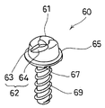
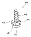
図1は遊技機に固定された基盤ケースの平面図、図2は基盤ケースの要部分解斜視図、図3はケースカバーをケース本体に固定した状態の要部斜視図、図4はケースカバーをケース本体に固定した状態の第3の取付部以外の取付部及び第3の固定部以外の固定部付近の断面図、図5はケースカバーをケース本体に固定した状態の第3の取付部及び第3の固定部付近の断面図、図6は破断部を全て破断した状態のケースカバー及びケース本体の要部斜視図、図7は止めネジの斜視図、図8は下から見た止めネジの斜視図を各々示す。
(基盤ケース)
図1中、10は、基盤ケースを示すものであり、この基盤ケース10は、透明又は半透明な樹脂板を用い、又、半透明又は不透明な樹脂板に小孔を多数設けた樹脂板などを用い、全体として内部に収納したものが外部から判別可能な樹脂板によって形成されており、例えば遊技機Mとしてのスロットマシン(図示せず)の機内に予め取り付けられたベース11に固定される。
(Explanation of drawings)
1 to 8 show an embodiment of the present invention.
1 is a plan view of the base case fixed to the gaming machine, FIG. 2 is an exploded perspective view of the main part of the base case, FIG. 3 is a perspective view of the main part with the case cover fixed to the case body, and FIG. FIG. 5 is a cross-sectional view of the mounting portion other than the third mounting portion in a state where the case is fixed to the case main body and the vicinity of the fixing portion other than the third fixing portion, and FIG. 5 is the third mounting portion in a state where the case cover is fixed to the case main body. FIG. 6 is a perspective view of the main part of the case cover and the case main body in a state in which all of the rupture portions are broken, FIG. 7 is a perspective view of a set screw, and FIG. The perspective view of a screw is shown, respectively.
(Base case)
In FIG. 1,
また、前記基盤ケース10は、制御基盤(図示せず)を収納するケース本体20と、このケース本体20に固定されてケース本体20を覆うケースカバー30とを備えている。
なお、本実施の形態の一例では、遊技機Mとしてスロットマシンを例に挙げて説明したが、基盤ケース10を用いて制御基盤が取り付けられる遊技機Mは、スロットマシンに限られず、制御基盤を必要とする遊技機、例えばパチンコ機、アレンジボール機などであってもよい。
(ベース)
前記ベース11は、基盤ケース10の外周よりも一回り大きな形状を有し、基盤ケース10の底面を収納可能に形成されている。
The
In the example of the present embodiment, the slot machine is described as an example of the gaming machine M. However, the gaming machine M to which the control base is attached using the
(base)
The
また、前記ベース11は、基盤ケース10の底面と対向する底面に、遊技機M側への固定のための固定ネジ12を介して遊技機Mに固定されている。このように、ベース11は、基盤ケース10の底面と対向する底面において、基盤ケース10をベース11に収納した状態では、ベース11を遊技機Mから取り外すことができないようになっている。
The
また、前記ベース11には、その左右の角部に、ケース本体20及びケースカバー30を連結するための連結部13が突出した状態で左右一対の4個づつ形成されている。前記各連結部13は、ケース本体20側に突出して形成され、その先端には、ネジ貫通穴14が形成されている。
(ケース本体)
前記ケース本体20は、図には詳しく説明しないが、全体として遊技機Mと接する位置とは反対側を開口した箱状をなし、その中央に形成された基盤収納部21と、前記基盤収納部21の左右斜め両側に張り出してケースカバー30を取り付けるための左右一対の取付部50が5組と、その下端に形成された、L字の短辺を下方に向けて突出させた横並びに並んだ3個のヒンジ部22と備えている。
Further, the
(Case body)
Although the
そして、前記基盤収納部21は、制御基盤が収納可能に形成されている。この制御基盤は、図には示さないが、入賞判定やメダルの払い出し数などの遊技に関する制御を行うための基盤であって、予め遊技に関するプログラムを記憶したROMやRAM、遊技に関する制御を行うCPUなどを備えるとともに、遊技機の表側に配置されたスイッチ(図示せず)、ランプ(図示せず)や回転リール(図示せず)などと接続されている。
The
また、前記取付部50は、基盤収納部21の側方に沿って所定の間隔を介して並んで配置され、右上から左下にかけて、第1、第2、第3、第4、第5として左右に各5個設けている。そして、ケースカバー30が固定される際には、又はケースカバー30とともに遊技機Mに固定される際には、前記左右一対の取付部50を一組として用いる。なお、前記左右一対の取付部50は、左右対称に配置されているため、以降、特に断りのない限り、便宜上、左側の取付部50について説明する。
In addition, the mounting
さらに、基盤収納部21の斜め上方に突出して配置された5個の取付部50のうち、その中央の第3の取付部50を除き、全て同じ構成を備えていることから、特に断りのない限り、第1の取付部50及び第3の取付部50についてのみ説明し、残る第2、第4及び第5の取付部については、各々ベース11の4つの取付部50に対応して配置されるが、第1の取付部50と同じ構成であることから、その説明を省略する。
Further, among the five mounting
前記第1の取付部50は、前記ベース11の連結部13に対応する位置に、基盤収納部21から斜め左側に張り出した1本の破断部52を有している。
前記破断部52は、例えばニッパなどの簡単な工具を用いて切断可能な幅に形成されている。また、この破断部52の先端は円筒状に形成され、その上端には、下端まで貫通して止めネジ60が進退可能な直径を備えた通過穴51がベース11のネジ貫通穴14に連続するように形成されている。
The first mounting
The breaking
前記第3の取付部50は、ベース11の連結部13が形成されていない位置に、前記第1の取付部50と同様に、基盤収納部21から斜め左側に張り出した1本の破断部52を有している。
そして、この破断部52の先端は円筒状に形成され、その上端には、止めネジ60がねじ込み可能な取付穴53が、前記通過穴51と異なり、ベース11まで貫通することなく形成されている。
(止めネジ)
前記取付穴53にねじ込まれる止めネジ60は、その頭部61にドライバーによりねじ込み可能とする差込溝62が形成されている。この差込溝62は、止めネジ60の中心軸を回転中心とした反時計回り方向の側面には、差込溝62の底面から上方に向けて緩やかに上昇するように傾斜面64が形成され、時計回り方向は略垂直な垂直面とした垂直部63を形成している。
The third mounting
The tip of the fractured
(Set screw)
The
したがって、止めネジ60をねじ込む時計回りの方向には、ドライバーの先端の側面を垂直部63に当ててドライバーの回転を止めネジ60に伝達することより、止めネジ60をドライバーによって回転させることができても、ドライバーを反時計回り方向に回して止めネジ60を緩めようとするとき、ドライバーの先端が傾斜面64にしたがって上昇し、止めネジ60を緩めることを困難としている。
Therefore, in the clockwise direction in which the
更に、この止めネジ60は、鍔部65を形成して頭部61の下端面を大きくし、この下端面には、段差部67を形成している。この段差部67は、止めネジ60を緩める回転方向である反時計回り方向を垂直面とし、鍔部65の肉厚を反時計方向に順次厚くして傾斜部68を形成し、段差部67で鍔部65の肉厚を戻すように薄くしている。
したがって、この止めネジ60のネジ部69を取付穴53にネジ込み、頭部61の下端面を固定穴73の周縁上端面に圧接しておけば、この止めネジ60を反時計回り方向に回転させて緩めようとするとき、段差部67によって初期回転抵抗が大きくなり、又、前述のように差込溝62の反時計回りの回転方向に傾斜面64を形成しているため、ドライバーにより止めネジ60を緩めて抜き取ることができない。
(ケースカバー)
前記ケースカバー30は、前記ケース本体20と同様に略方形状をなし、前記ケース本体20
の開口部分の全部を塞ぐ大きさに形成されている。
Further, the
Therefore, if the
(Case cover)
The case cover 30 is substantially square like the
It is formed in a size that covers the entire opening.
また、前記ケースカバー30は、その左右の斜め上部には、前記ケースカバー30を前記ケ
ース本体20に固定するための左右一対の固定部70が、ケースカバー30の角部に沿って所定
の間隔を介して5個設けられている。
また、前記ケースカバー30は、取付部50とは反対側の一端を、ヒンジ部22を介してケースカバー30と開閉可能に軸支されている。このヒンジ部22は、図には詳しく説明しないが、ケースカバー30側のL字状の突出部分をケース本体20側の孔に差し込むことにより、仮止め状態となり、取付部50と固定部70とを固定していない状態では、このヒンジ部22を介して、ケース本体20に対してケースカバー30が開放可能な状態となり、取付部50と固定部70とを固定した状態では、ケース本体20側の孔に差し込まれた突出部分が抜けないような構造となっている。
The case cover 30 has a pair of left and right fixing
The case cover 30 is pivotally supported at one end opposite to the mounting
前記左右一対の5個の固定部70は、前記ケース本体20の各取付部50に各々対応して配置され、各々ケースカバー30側面から左右方向に張り出して設けられており、右上から左下にかけて、第1、第2、第3、第4、第5の5つの固定部70から構成されている。
そして、いずれも同一の構成を備えており、左右一組の固定部70についても左右対称に形成されていることから、特に断りのない限り、一組の固定部70であって、左側の取付部50に対応する左側の固定部70についてのみ説明する。
The pair of left and right five fixing
Since both have the same configuration, and the left and right set of fixing
前記左側の固定部70は、所定の対向間隔をもってケースカバー30の側面から外側に張り出した2本の破断部71と、この破断部71の先端に設けられて円筒状をなす頭部カバー72とを備えている。
前記2本の破断部71は、例えばニッパなどの簡単な工具を用いて切断可能な幅に形成されている。また、ニッパなどの切断具の先端が挿入しやすいように、所定の対向間隔を介して配置されている。破断の方法は、いずれの方法であってもよいが、簡単に切断するためには、好ましくは、2本の破断部71の間に形成された対向間隔に、切断具の先端を挿入する方法がよい。また、破断部71を切断可能に形成すると、切断のため以外の外部からの圧力を受けて破損してしまうため、破断部71を切断可能とするとともに工具を用いて破断する以外は容易に破断しないような構成として、前記2本の破断部71で頭部カバー72を支持することとしている。
The left fixed
The two
この頭部カバー72には、その底部に、前記取付部50の通過穴51に対応して止めネジ60をねじ込み可能な固定穴73が形成されている。
また、第1、第2、第4及び第5の固定部70については、前記固定穴73から止めネジ60をねじ込んで、取付部50の通過穴51を通過し、ベース11の連結部13のネジ貫通穴14にまでねじ込んで締め込むことにより、基盤ケース10をベース11に固定することができ、それによって、ケースカバー30をケース本体20に固定することもできる。
A fixing
Further, the first, second, fourth and
左側に配置された、第1の固定部70を、対応する第1の取付部50に固定することにより、基盤ケース10をベース11に固定することができるが、更に固定を確実なものとするため、左側の第1の取付部50に第1の固定部70をネジ止めすると共に、対称的に位置する右側の固定部70の固定穴73から止めネジ60をねじ込んで、取付部50の通過穴51を通過し、ベース11の連結部13のネジ貫通穴14にまでねじ込んで締め込むことにより、基盤ケース10をベース11に固定すればよい。
The
また、頭部カバー72は、止めネジ60がねじ込み可能なように、止めネジ60の頭部61の外径よりも若干大きな内径を有しているが、止めネジ60の頭部61の外径と頭部カバー72の内径との差は、例えばペンチなどの工具が挿入されない程度の差のみを有するように形成されている。したがって、止めネジ60を、奥までねじ込んでしまうと、ペンチなどの工具で止めネジ60の頭部61や鍔部65を挟み込んで、強引に止めネジ60を反ねじ込み方向(反時計回り)に回転させて止めネジ60を緩めることはできない。
The
したがって、一旦、第1の固定部70の固定穴73にねじ込まれ、通過穴51を通過し、ネジ貫通穴14にまで締め込まれた止めネジ60は、この止めネジ60を緩めることができないことから、第1の取付部50及び対応する第1の固定部70を用いて、ケース本体20を、ケースカバー30を介して遊技機Mに一緒に固定することができる。
Therefore, the
また、第3の固定部70については、前記固定穴73から止めネジ60をねじ込んで、取付部50の取付穴53にまでまで締め込むことにより、第3の固定部70を、同じく対応する位置の第3の取付部50に固定することができる。
第3の取付部50の取付穴53は、ケースカバー30を貫通することなく形成されているのでケースカバー30をケース本体20に固定することができる。
Further, with respect to the third fixing
Since the mounting
このように、第3の取付部50と第3の固定部70を用いて、ケースカバー30をケース本体20にのみ固定することができ、遊技機Mに固定する前に、制御基盤を、基盤ケース10の内部に収納し、開封の痕跡なしに取り出すことを防止することができる。
また、第3の取付部50の取付穴53にねじ込まれた止めネジ60も緩めることもできないから、ケース本体20からケースカバー30を取り外すことができない。
In this way, the case cover 30 can be fixed only to the
Further, since the
そして、いずれの取付部50及び固定部70を用いても、ケース本体20からケースカバー30
を取り外すには、前記固定部70の2本の破断部71を破断させる必要がある。
特に、第1、第2、第4及び第5の取付部50のいずれか及び対応する第1、第2、第4及び第5の固定部70のいずれかを用いて、ケース本体20及びケースカバー30を遊技機Mに固定した場合には、基盤ケース10を、ケース本体20とケースカバー30とに分離することなく、遊技機Mから取り外そうとしてもできない。
Then, regardless of which mounting
In order to remove the two, it is necessary to break the two
In particular, the
第1の固定部70と第1の取付部50とを用いて、基盤ケース10を遊技機Mに固定した状態で、双方の破断部52,71を破断させると、破断した固定部70は取付部50に対してネジ止めにより固定されるとともに、ベース11に固定されているが、固定部70はケースカバー30に対して破断部71のみで連続し、取付部50もケース本体20に対して破断部52のみで連続していることから、双方の破断部52,71の破断によって、固定部70はケースカバー30から、取付部50はケース本体20から離脱可能となり、この状態で基盤ケース10をベース11から離れる方向へ引けば、取付部50と取付部50にネジ止めされた状態の固定部70とは、双方の破断部52,71の破断により、ケース本体20及びケースカバー30から離脱してベース11に残り、基盤ケース10をベース11から取り外すことができる。
When the
なお、基盤ケース10をベース11から取り外してから、再びケース本体20にケースカバー30を固定するには、双方の破断部52,71が未だ破断されていない、他の左右一対の取付部50と固定部70とを用いればよい。
また、固定部70の頭部カバー72の深さは、止めネジ60を固定穴73にのみねじ込んで仮止めしている状態でも、止めネジ60の頭部61が頭部カバー72の上端から突出しない程度の深さとし、止めネジ60の長さにほぼ等しい高さの頭部カバー72としている。
In order to fix the case cover 30 to the
Further, the depth of the
したがって、まだ、ケースカバー30をケース本体20に固定していない状態で、固定穴73にのみ止めネジ60をねじ込んで仮止めしておいても、止めネジ60が他のものに当たってしまうことがなく、例えば運搬時にも止めネジ60を仮止めしておくことができる。また、一組の左右一対の取付部50と固定部70を用いて固定している場合であって、使用していない他の組の左右一対の取付部50と固定部70にも、各固定穴73にのみ止めネジ60をねじ込んでおくことで、止めネジ60を仮止めしておくことができる。
Therefore, even when the case cover 30 is not fixed to the
このため、基盤ケース10をベース11に固定する際に、別に用意した止めネジ60を紛失したり、別の梱包などから出したりすることがないことから、迅速な作業が可能となるとともに、運搬時に、別の梱包を必要としない。
また、第3の取付部50と第3の固定部70とを、止めネジ60を用いて、ケース本体20にのみケースカバー30を固定することができるが、ケース本体20からケースカバー30を取り外すには、固定部70は、破断部71のみでケースカバー30と連続しているから、破断部71を破断して、ケースカバー30を引くと、ケース本体20からケースカバー30を取り外すことができ、開放の痕跡が残ることとなる。
For this reason, when fixing the
In addition, the case cover 30 can be fixed only to the case
つぎに、上記構成を備えた基盤ケース10を用いて、遊技機Mの裏側に固定され、制御基盤を収納したケース本体20に、ケースカバー30を固定する手順、ケース本体20にケースカバー30が固定された状態からケースカバー30を取り外す手順及びケース本体20に再びケースカバー30を固定する手順について、説明する。
まず、遊技機にベース11を、固定ネジ12を用いて予め固定する。
Next, a procedure for fixing the case cover 30 to the case
First, the
そして、制御基盤を収納したケース本体20を、遊技機Mの裏側に固定した状態とし、ケースカバー30をこのケース本体20に取り付ける。
前記ケース本体20にケースカバー30を取り付けるには、ケース本体20とケースカバー30とが分離している状態から、ヒンジ部22を係合させて、ヒンジ部22を中心としてケースカバー30を回動させて、前記取付部50と固定部70とを合わせる。
Then, the
To attach the case cover 30 to the case
つぎに、ケース本体20にケースカバー30を仮止めした状態で、各固定部70に仮止めしている止めネジ60のうち、第1、第2、第4又は第5の固定部70に仮止めしている止めネジ60のいずれかを、対応する第1、第2、第4又は第5の取付部50のにねじ込むものである。
例えば、第1の固定部70の固定穴73に仮止めされた止めネジ60をドライバーにより更にねじ込んで、止めネジ60を、第1の取付部50の通過穴51を通過させ、さらに、止めネジ60をねじ込むことにより、ベース11のネジ貫通穴14にまで到達させネジ貫通穴14にまでねじ込むと、ねじ込まれた状態で、ケース本体20とケースカバー30とがベース11に固定される。そして、ベース11は、固定ネジ12で予め遊技機Mに固定されていることから、基盤ケース10は、遊技機Mに固定されることとなる。
Next, in the state where the case cover 30 is temporarily fixed to the
For example, the
なお、取付部50の通過穴51を通過し、ネジ貫通穴14までねじ込まれた止めネジ60は、前記のようにねじ込み方向にのみ、ねじ込み可能として形成されていることから、ドライバーなどのねじ込み用の工具を用いて止めネジ60を締め付けることはできても、止めネジ60を緩めることができない。また、通過穴51を通過し、ネジ貫通穴14までねじ込まれた止めネジ60は、頭部カバー72によって止めネジ60の頭部61がその上端まで覆われているので、ペンチなどのネジ頭部を挟む工具によって止めネジ60の頭部61を挟めず、結果として止めネジ60を緩めることができない。
Note that the
したがって、止めネジ60を緩めることによっては、ケース本体20からケースカバー30を取り外すことはできないとともに、ケース本体20とケースカバー30とが固定された状態で、遊技機Mから取り外すこともできない。
ところで、第3の取付部50と第3の固定部70とを用いた場合は、ケース本体20にケースカバー30を固定できるのみであって、ケース本体20にケースカバー30を固定した場合には、取り外した痕跡なしに、ケース本体20からケースカバー30を取り外すことができない。
開放の痕跡が、破断部71の破断という形で残る。
Therefore, the case cover 30 cannot be removed from the
By the way, when the third mounting
The trace of opening remains in the form of breakage of the
つぎに、基盤ケース10をベース11を取り外すには、ニッパなどの切断具を用いて固定部70の2本の破断部71及び取付部50の破断部52を破断する。両各破断部52,71は、ニッパなどの切断具によって破断しやすい幅に形成され、特に2本の破断部71は、所定の対向間隔を介して並んでいることからニッパなどの切断具の先端が挿入し易いようになっている。
Next, in order to remove the base 11 from the
また、固定部70は、ケースカバー30と2本の破断部71のみで連続していることから、2本の破断部71を切断すると、固定部70とケースカバー30とは離脱可能となる。
さらに、取付部50は、ケース本体20と、破断部52のみで連続していることから、破断部52を切断すると、取付部50とケース本体20とは離脱可能となる。
Further, since the fixing
Furthermore, since the
したがって、基盤ケース10をベース11から離脱する方向に引くと、基盤ケース10は、固定部70及び取付部50をベース11にネジ止めしたまま、ベース11から取り外すことができる。
このように、ベース11から基盤ケース10を取り外し、ケース本体20からケースカバー30を取り外すためには、止めネジ60により取付部50にねじ止めされた固定部70の2本の破断部71及び取付部50の破断部52を破断しなければならないことから、容易にケースカバー30を開放することができず、ケースカバー30をみだりに開放して、制御基盤を改造したり、プログラムを記憶したROMなどの交換したり、基盤ケース10ごとベース11から取り外して交換することもできない。
Therefore, when the
In this way, in order to remove the
また、ケースカバー30を通常の検査などの都合以外で開放した場合には、両破断部52,71の破断をもって開放した痕跡となることから、不正に開放したことが、直ちに判明する。
つぎに、ケース本体20からケースカバー30を取り外して、制御基盤の検査を行った後に、ケースカバー30をケース本体20に再び固定した状態でベース11に固定するためには、先に両破断部52,71を破断した、一組の左右一対の固定部70と取付部50とは用いることができないから、次の一組の一対の固定部70と取付部50とを用いて、先に説明した要領で、固定部70からネジを挿入し、通過穴51を通過させ、ベース11のネジ貫通穴14にねじ込むことにより、ケースカバー30をケース本体20を介してベース11に固定すればよい。
In addition, when the case cover 30 is opened for reasons other than normal inspection or the like, it is immediately revealed that the case cover 30 has been opened improperly because it becomes a trace of opening when both the
Next, after removing the case cover 30 from the
なお、第3の取付部50と第3の固定部70とを用いて、ケース本体20とケースカバー30とを固定すると、単に、ケース本体20からケースカバー30を開放した場合に、その痕跡を残すことができる。このため、基盤ケース10をベース11に固定する前に、第3の取付部50と第3の取付部70とを用いて、ケース本体20にケースカバー30を固定しておくと、遊技機に取り付ける前にも開放した痕跡が残るようにできる。
If the case
本実施の形態の一例においては、各一対の取付部50と固定部70とは、基盤ケース10とベース11とを固定するためのものが全部で4組設けられていることから、最初の固定を除き、ケース本体20にケースカバー30を3回再固定することができる。
また、検査のためにケースカバー30を開放した事実を記録しておけば、記録にない破断部52,71の破断の事実が認められれば、直ちにケースカバー30を不正に開放したことが判明して便利である。
In the example of the present embodiment, each pair of mounting
In addition, if the fact that the
そして、左右一対の取付部50と固定部70とを備えていることから、破断部52,71を破断することにより、ケースカバー30をケース本体20から取り外しても、破断されていない一組の左右一対の取付部50と固定部70とを用いて、再びケース本体20にケースカバー30を固定することができ、極めて経済的である。
また、基盤ケース10をベース11に固定することなく、ケースカバー30をケース本体20に固定することのできる第3の固定部50と第3の取付部70とを用いて止めネジ60で固定すれば、基盤ケース10を遊技機Mに固定する前の開放をも有効に防止することができる。
And since it includes a pair of left and right mounting
Further, the
10 基盤ケース
11 ベース
12 固定ネジ
13 連結部
14 ネジ貫通穴
20 ケース本体
21 基盤収納部
22 ヒンジ部
30 ケースカバー
50 取付部
51 通過穴
52 破断部
53 取付穴
60 止めネジ
61 頭部
62 差込溝
63 垂直部
64 傾斜面
65 鍔部
67 段差部
68 傾斜部
69 ネジ部
70 固定部
71 破断部
72 頭部カバー
73 固定穴
M 遊技機
10 Base case
11 base
12 Fixing screw
13 Connecting part
14 Screw through hole
20 Case body
21 Base storage
22 Hinge part
30 Case cover
50 Mounting part
51 passage hole
52 Break
53 Mounting hole
60 Set screw
61 head
62 Insertion groove
63 Vertical section
64 Inclined surface
65 Buttocks
67 Step
68 Slope
69 Screw part
70 Fixed part
71 Broken part
72 Head cover
73 Fixed hole M Game machine
Claims (1)
前記基盤ケースは、
ベースに固定されるケース本体と、
前記ケース本体を覆い、前記ケース本体に固定されるケースカバーとを備え、
前記ケース本体には、
前記ケース本体に設けられた第1の破断部を介して、前記ケースカバーを取り付けるための複数の取付部を有し、
前記ケースカバーには、前記複数の取付部に各々対応し、各取付部に固定可能で、かつ、前記ケースカバーに設けられた第2の破断部を介して複数の固定部を有し、
前記固定部の少なくとも一つは、該固定部に対応する前記取付部に固定され、
前記第2の破断部のみを破断することによって前記ケース本体から前記ケースカバーを取り外し可能に形成されるとともに、前記基盤ケースを再度遊技機に取り付けるに際し、取付に用いていない固定部を次回以降の固定に使用できるようにし、
前記第2の破断部と前記第1の破断部とは、対の関係を備え、
前記第2の破断部は、
基盤ケースが前記ベースに取り付けられた状態において、前記第1の破断部と所定の間隙を介して重なって、前記第1の破断部のみの破断を妨げる位置に配置され、
上記基盤ケースには、
前記第1の破断部と第2の破断部とが重なった状態で、側方からの前記第1の破断部の破断を妨げる位置に、立ち壁が設けられていることを特徴とする遊技機用の基盤ケース。
In the base case that houses the control base for controlling the gaming machine and is attached to the base,
The base case is
A case body fixed to the base;
A case cover that covers the case body and is fixed to the case body;
In the case body,
Through the first breaking portion provided on the case body having a plurality of mounting portions for mounting the case cover,
The case cover corresponds to each of the plurality of attachment portions, can be fixed to each attachment portion, and has a plurality of fixing portions via a second fracture portion provided in the case cover,
At least one of the fixing parts is fixed to the attachment part corresponding to the fixing part,
The case cover is formed so as to be removable from the case main body by breaking only the second breakage portion, and when the base case is attached to the gaming machine again, a fixing portion that is not used for attachment is used for the next and subsequent times. To be used for fixing,
The second break portion and the first break portion have a paired relationship,
The second fracture portion is
In a state where the base case is attached to the base, the base case overlaps with the first breakage portion via a predetermined gap, and is disposed at a position that prevents the breakage of only the first breakage portion,
In the above base case,
A game machine, wherein a standing wall is provided at a position that prevents the first breakage portion from being broken from the side in a state where the first breakage portion and the second breakage portion overlap each other. Base case for.
Priority Applications (1)
| Application Number | Priority Date | Filing Date | Title |
|---|---|---|---|
| JP2009184595A JP4688180B2 (en) | 2009-08-07 | 2009-08-07 | Base case for gaming machines |
Applications Claiming Priority (1)
| Application Number | Priority Date | Filing Date | Title |
|---|---|---|---|
| JP2009184595A JP4688180B2 (en) | 2009-08-07 | 2009-08-07 | Base case for gaming machines |
Related Parent Applications (1)
| Application Number | Title | Priority Date | Filing Date |
|---|---|---|---|
| JP06083699A Division JP4540019B2 (en) | 1999-03-08 | 1999-03-08 | Base case for gaming machines |
Publications (3)
| Publication Number | Publication Date |
|---|---|
| JP2009254884A JP2009254884A (en) | 2009-11-05 |
| JP2009254884A5 JP2009254884A5 (en) | 2009-12-24 |
| JP4688180B2 true JP4688180B2 (en) | 2011-05-25 |
Family
ID=41383037
Family Applications (1)
| Application Number | Title | Priority Date | Filing Date |
|---|---|---|---|
| JP2009184595A Expired - Fee Related JP4688180B2 (en) | 2009-08-07 | 2009-08-07 | Base case for gaming machines |
Country Status (1)
| Country | Link |
|---|---|
| JP (1) | JP4688180B2 (en) |
Citations (4)
| Publication number | Priority date | Publication date | Assignee | Title |
|---|---|---|---|---|
| JPH09225092A (en) * | 1996-02-23 | 1997-09-02 | Sophia Co Ltd | Control circuit apparatus |
| JPH10249021A (en) * | 1997-03-12 | 1998-09-22 | Fuji Shoji Kk | Circuit board case sealing device for pachinko machine |
| JPH10295910A (en) * | 1997-04-24 | 1998-11-10 | Sankyo Kk | Game machine |
| JP4540019B2 (en) * | 1999-03-08 | 2010-09-08 | サミー株式会社 | Base case for gaming machines |
-
2009
- 2009-08-07 JP JP2009184595A patent/JP4688180B2/en not_active Expired - Fee Related
Patent Citations (4)
| Publication number | Priority date | Publication date | Assignee | Title |
|---|---|---|---|---|
| JPH09225092A (en) * | 1996-02-23 | 1997-09-02 | Sophia Co Ltd | Control circuit apparatus |
| JPH10249021A (en) * | 1997-03-12 | 1998-09-22 | Fuji Shoji Kk | Circuit board case sealing device for pachinko machine |
| JPH10295910A (en) * | 1997-04-24 | 1998-11-10 | Sankyo Kk | Game machine |
| JP4540019B2 (en) * | 1999-03-08 | 2010-09-08 | サミー株式会社 | Base case for gaming machines |
Also Published As
| Publication number | Publication date |
|---|---|
| JP2009254884A (en) | 2009-11-05 |
Similar Documents
| Publication | Publication Date | Title |
|---|---|---|
| JP6078742B2 (en) | Caulking structure | |
| JP4540019B2 (en) | Base case for gaming machines | |
| JP2006142064A5 (en) | ||
| JP2006142064A (en) | Game machine | |
| JP2000254320A5 (en) | ||
| JP4688181B2 (en) | Base case for gaming machines | |
| JP5656033B2 (en) | Game machine | |
| JP2000014907A (en) | Board case for game machine | |
| JP4688180B2 (en) | Base case for gaming machines | |
| JP2009254885A5 (en) | ||
| JP2010069232A (en) | Game machine | |
| JP3701438B2 (en) | Base case for gaming machines | |
| JP2013150856A (en) | Game machine | |
| JP2009254884A5 (en) | ||
| JPH11226220A (en) | Circuit board case for game machine | |
| JP5850596B2 (en) | Game machine | |
| JP6052356B2 (en) | Game machine | |
| JP2009018113A (en) | Game machine | |
| JP2013165794A (en) | Circuit board for game machine | |
| JP5821933B2 (en) | Game machine | |
| JP4318627B2 (en) | Game machine | |
| JP5239682B2 (en) | Game machine | |
| JP5800068B2 (en) | Game machine | |
| JP2013215457A (en) | Board case | |
| JP5524000B2 (en) | Game machine board case |
Legal Events
| Date | Code | Title | Description |
|---|---|---|---|
| A621 | Written request for application examination |
Free format text: JAPANESE INTERMEDIATE CODE: A621 Effective date: 20090904 |
|
| A521 | Written amendment |
Free format text: JAPANESE INTERMEDIATE CODE: A523 Effective date: 20091109 |
|
| A131 | Notification of reasons for refusal |
Free format text: JAPANESE INTERMEDIATE CODE: A131 Effective date: 20100729 |
|
| A521 | Written amendment |
Free format text: JAPANESE INTERMEDIATE CODE: A523 Effective date: 20100927 |
|
| A131 | Notification of reasons for refusal |
Free format text: JAPANESE INTERMEDIATE CODE: A131 Effective date: 20101111 |
|
| A521 | Written amendment |
Free format text: JAPANESE INTERMEDIATE CODE: A523 Effective date: 20101227 |
|
| TRDD | Decision of grant or rejection written | ||
| A01 | Written decision to grant a patent or to grant a registration (utility model) |
Free format text: JAPANESE INTERMEDIATE CODE: A01 Effective date: 20110127 |
|
| A01 | Written decision to grant a patent or to grant a registration (utility model) |
Free format text: JAPANESE INTERMEDIATE CODE: A01 |
|
| A61 | First payment of annual fees (during grant procedure) |
Free format text: JAPANESE INTERMEDIATE CODE: A61 Effective date: 20110210 |
|
| R150 | Certificate of patent or registration of utility model |
Free format text: JAPANESE INTERMEDIATE CODE: R150 |
|
| FPAY | Renewal fee payment (event date is renewal date of database) |
Free format text: PAYMENT UNTIL: 20140225 Year of fee payment: 3 |
|
| FPAY | Renewal fee payment (event date is renewal date of database) |
Free format text: PAYMENT UNTIL: 20140225 Year of fee payment: 3 |
|
| R250 | Receipt of annual fees |
Free format text: JAPANESE INTERMEDIATE CODE: R250 |
|
| R250 | Receipt of annual fees |
Free format text: JAPANESE INTERMEDIATE CODE: R250 |
|
| R250 | Receipt of annual fees |
Free format text: JAPANESE INTERMEDIATE CODE: R250 |
|
| R250 | Receipt of annual fees |
Free format text: JAPANESE INTERMEDIATE CODE: R250 |
|
| LAPS | Cancellation because of no payment of annual fees |