JP4688143B2 - Liquid crystal display - Google Patents
Liquid crystal display Download PDFInfo
- Publication number
- JP4688143B2 JP4688143B2 JP2005157727A JP2005157727A JP4688143B2 JP 4688143 B2 JP4688143 B2 JP 4688143B2 JP 2005157727 A JP2005157727 A JP 2005157727A JP 2005157727 A JP2005157727 A JP 2005157727A JP 4688143 B2 JP4688143 B2 JP 4688143B2
- Authority
- JP
- Japan
- Prior art keywords
- liquid crystal
- light
- pair
- electrode
- crystal layer
- Prior art date
- Legal status (The legal status is an assumption and is not a legal conclusion. Google has not performed a legal analysis and makes no representation as to the accuracy of the status listed.)
- Expired - Fee Related
Links
Images


Description
本発明は、液晶表示装置(liquid crystal display;LCD)に関する。 The present invention relates to a liquid crystal display (LCD).
図9(A)及び(B)は、それぞれカラー表示を行う液晶表示素子の内部構成例を示す概略的な分解斜視図である。
図9(A)を参照する。液晶表示素子は、対向配置される上側基板31及び下側基板32、及び、その間に挟持される液晶層39を含んで構成される。上側基板31及び下側基板32は、たとえば平板なガラス基板と、その対向面上に、ITO(indium tin oxide)等の透明導電材で形成され、所定のパタンを有する電極を備える。液晶層39は、たとえば負の誘電率異方性(Δε<0)をもつネマティック液晶39aで形成されるネマティック液晶層である。
FIGS. 9A and 9B are schematic exploded perspective views showing an example of the internal configuration of a liquid crystal display element that performs color display.
Reference is made to FIG. The liquid crystal display element includes an
上側基板31及び下側基板32の外側に、一対の上側及び下側偏光板41,42がクロスニコル状態に配置される。上側及び下側偏光板41,42は、それぞれ面内方向に透過軸を有し、透過軸の方向に偏光する光だけを透過させる。
On the outside of the
白色バックライト52が、下側偏光板42の外側に配置される。白色バックライト52は、たとえば冷陰極蛍光管(cold cathode fluorescent lamp;CCFL)を用いて構成される。無機白色LED(light emitting diode)、有機LED等を用いて構成される場合もある。
A
上側及び下側基板31、32の電極間に接続される電圧印加手段で、液晶層39に電圧を印加することによって、液晶分子39aの配向状態が変化する。液晶分子39aの配向状態の変化によって、透過光の偏光状態も変化する。白色バックライト52から発せられ、液晶層39を通過した光が、上側偏光板41を透過するときに「明」表示、上側偏光板41に遮蔽されるときに「暗」表示が行われる。
By applying a voltage to the
カラー表示を行うために、上側及び下側基板31、32間に、エリアカラーフィルタ49及びブラックマスク51が配置される。
エリアカラーフィルタ49は、たとえば赤色部49r、緑色部49g、青色部49b、及び白色部49wを含んで構成される。図示の液晶表示素子においては、白色バックライト52から発せられた光が、エリアカラーフィルタ49の異なる色の領域(各色部49r,g,b,w)を透過することで、領域ごとに複数色の表示が可能になる。
In order to perform color display, an
The
ブラックマスク51は、コントラストや色純度を高めるために配置される。
所定の表示を行うために、駆動回路53が接続される。
図9(A)に示す構成によって、カラーによるセグメント表示、セグメントとドットとを併用した表示、及びフルドット表示が可能である。
The
A
With the structure shown in FIG. 9A, color segment display, display using a combination of segments and dots, and full dot display are possible.
本図に示したような、白色光源で照明する透過型構造の液晶表示素子は、複雑な色表現には不適当である。
色表示品位の向上のため、マイクロカラーフィルタ方式を採用する液晶表示素子が提案されている。
The liquid crystal display element having a transmissive structure illuminated with a white light source as shown in the figure is not suitable for complicated color expression.
In order to improve color display quality, a liquid crystal display element employing a micro color filter method has been proposed.
マイクロカラーフィルタ方式は、特に、フルドット表示タイプの液晶表示素子に導入され、たとえば微細なドットを赤(R)、緑(G)、青(B)に色分けし、3ドット1組(1画素)としてカラー表示を行う。 The micro color filter system is particularly introduced in a full-dot display type liquid crystal display element. For example, fine dots are color-coded into red (R), green (G), and blue (B), and one set of three dots (one pixel). ) Is displayed in color.
しかしこの方式においても、ドットが大きい場合には、人間の目の空間分解能により、1画素が複数ドットから成り立っていることが認識されてしまい、高い表示品位を実現できないことがある。また、1画素を複数のドットで構成するので、光利用効率が低下する。このため白色バックライト52の輝度を向上させる必要があり、消費電力が増大する。
However, even in this method, when the dots are large, it may be recognized that one pixel is composed of a plurality of dots due to the spatial resolution of the human eye, and high display quality may not be realized. Further, since one pixel is composed of a plurality of dots, the light use efficiency is lowered. For this reason, it is necessary to improve the brightness of the
図9(B)に、カラー表示を行う液晶表示素子の他の内部構成例を示す。
図9(A)に示す液晶表示素子においては、液晶セル内にエリアカラーフィルタやブラックマスクを配置したが、図9(B)に示す液晶表示素子においては、液晶セル内に、それらを配置しない。また、カラー表示を行うために、白色バックライト52に代え、マルチカラーバックライト55を用いる。
FIG. 9B illustrates another example of the internal structure of a liquid crystal display element that performs color display.
In the liquid crystal display element shown in FIG. 9A, an area color filter and a black mask are arranged in the liquid crystal cell, but in the liquid crystal display element shown in FIG. 9B, they are not arranged in the liquid crystal cell. . In order to perform color display, a
マルチカラーバックライト55は、複数の色発光が可能なバックライトであり、たとえばRGBマルチカラーLED光源を用いる。マルチカラーバックライト55から発せられた光が、上側偏光板41を透過したとき、発せられた光の色によって、「明」が表示される。バックライト同期駆動回路54は、マルチカラーバックライト55による発光と、液晶層39の液晶分子39aの配向状態とを同期させる。
The
図9(B)に示したような、カラーフィルタを備えない液晶表示素子を駆動する方法として、フィールドシーケンシャル(field sequential;FS)駆動法が知られている。 A field sequential (FS) driving method is known as a method for driving a liquid crystal display element that does not include a color filter as shown in FIG. 9B.
フィールドシーケンシャル駆動法は、R、G、Bの画像データを時間分解して表示し、残像が認識できないほど高速にその画像データを切り替えることで、観察者にその混色画像を認識させる駆動法である。 The field sequential driving method is a driving method in which image data of R, G, and B is time-resolved and displayed, and the image data is switched at such a high speed that an afterimage cannot be recognized, thereby allowing an observer to recognize the mixed color image. .
図10に、FS駆動法の駆動タイミングチャートの一例を示す。なお、本タイミングチャートにおいては、液晶表示素子は、表示部1、表示部2、・・、表示部nのn個の表示領域が画定され、上下基板間に電圧が印加されたとき(図中には「ON」で表示。)に、「明」表示を行うノーマリブラックタイプと想定してある。
FIG. 10 shows an example of a driving timing chart of the FS driving method. In this timing chart, the liquid crystal display element has a
FS駆動法によれば、1フレーム期間、たとえば16.7msで1つの画像を表示する。1フレーム期間は3つのサブフレーム期間(ここでは、時間軸に沿って、サブフレーム期間1、2、3と呼ぶ。)SBから構成され、各サブフレーム期間において、R,G,Bのうちの1色のデータを表示する。
According to the FS driving method, one image is displayed in one frame period, for example, 16.7 ms. One frame period is composed of three subframe periods (here, called
表示部1においては、サブフレーム期間1及び2で上下基板間に電圧が印加されて「明」状態(入射光を透過する状態)となり、サブフレーム期間3では、電圧無印加状態とされて、「暗」状態(入射光を透過しない状態)となる。一方、マルチカラーバックライトは、サブフレーム期間1において赤(R)を、サブフレーム期間2及び3において、それぞれ緑(G)及び青(B)を発光する。このため、表示部1においては、1フレーム期間中に、赤(R)と緑(G)の光が透過され、両色の混色である黄が観察者の目に認識される。
In the
同様に、表示部2においては、サブフレーム期間1に透過した赤(R)、及びサブフレーム期間3に透過した青(B)により、マゼンダが表示される。
表示部nにおいては、サブフレーム期間2に透過した緑(G)がそのまま観察者の目に認識される。
Similarly, on the display unit 2, magenta is displayed by red (R) transmitted in the
In the display unit n, green (G) transmitted in the subframe period 2 is directly recognized by the observer's eyes.
なお、マルチカラーバックライトの発光が、各サブフレーム期間のはじめの方でなされていないのは、印加電圧に対する液晶層の応答はバックライトのそれに比べて遅いため、液晶層がある程度応答するまでのブランク期間を設け、液晶層が光を透過する期間と、バックライトの発光期間とを一致させるように調整する目的である。 The reason why the multi-color backlight does not emit light at the beginning of each subframe period is that the response of the liquid crystal layer to the applied voltage is slower than that of the backlight. The purpose is to provide a blank period and to adjust the period during which the liquid crystal layer transmits light and the light emission period of the backlight.
ノーマリホワイトモードの液晶表示素子においてFS駆動法を用い、背景を白色表示としたポジ表示状態で、セグメント表示部分をカラー表示とする表現が可能となる。なお、これは図9(A)に示したカラー表示液晶表示素子では不可能である。 In the normally white mode liquid crystal display element, the FS driving method is used, and in the positive display state in which the background is displayed in white, the segment display portion can be expressed in color. This is impossible with the color display liquid crystal display element shown in FIG.
しかしこのFS駆動法では、暗い場所での観察時に観察者が視線を移したときや液晶表示素子が振動した場合に、各サブフレームの単色表示が人間の目に認識されるカラーブレーク現象が現れ、特に白表示領域は虹のように認識される場合もある。カラーブレーク現象が生じた場合、表示外観が悪く、また、人間の心理的にも見難い表示となる。 However, in this FS driving method, when an observer changes his / her line of sight when observing in a dark place or when the liquid crystal display element vibrates, a color break phenomenon occurs in which the monochrome display of each subframe is recognized by the human eye. In particular, the white display area may be recognized as a rainbow. When the color break phenomenon occurs, the display appearance is poor, and the display is difficult for human psychology.
本願発明者らは、1フレームにおいて画像を形成するときに、複数のサブフレームで光源を点灯させるとカラーブレーク現象が発生することを突きとめ、先の出願において、それまでR、G、Bで発光させていたバックライトを、1サブフレーム内で所望の色に発光させ、表示に反映させればよいとする提案を行った。(たとえば、特許文献1参照。)
図11に、先の提案によるFS駆動法の駆動タイミングチャートの一例を示す。
The inventors of the present application have found that a color break phenomenon occurs when a light source is turned on in a plurality of subframes when forming an image in one frame. A proposal has been made that the backlight that has been made to emit light should emit light in a desired color within one subframe and be reflected in the display. (For example, see
FIG. 11 shows an example of a driving timing chart of the FS driving method proposed previously.
本タイミングチャートに示すFS駆動法においては、サブフレーム期間1でマルチカラーバックライトから赤(R)の光を発光し、サブフレーム期間2及び3では、マルチカラーバックライトから、それぞれ黄(Y)及びシアン(C)の光を発光する。黄(Y)の光は、赤(R)と緑(G)の光の加算によって形成し、シアン(C)の光は緑(G)と青(B)の光の加算により形成する。
In the FS driving method shown in this timing chart, red (R) light is emitted from the multi-color backlight in the
表示部1においては、サブフレーム期間1のみで上下基板間に電圧が印加されて「明」状態(入射光を透過する状態)となり、赤(R)による表示を行う。同様に、表示部2及びnにおいては、それぞれサブフレーム期間3及び2のみで上下基板間に電圧が印加されて「明」状態となり、シアン(C)及び黄(Y)による表示を行う。
In the
先の出願に係る液晶表示素子の駆動方法によれば、1つの色表示を1つのサブフレームで完結させ、また、バックライトの発光色をR、G、Bの原色だけではなく、YやCなどの混色を含むものとすることにより、カラーブレークを防止し、良好な表示を実現することができる。 According to the driving method of the liquid crystal display element according to the previous application, one color display is completed in one subframe, and the light emission color of the backlight is not limited to the primary colors of R, G, B, but also Y and C By including color mixture such as the above, a color break can be prevented and a good display can be realized.
この液晶表示素子の駆動方法においては、バックライトの発光色を1フレームごとに変更することが可能であるため、任意の色表示を容易に実現することができる一方、3つのサブフレームの混色が白色にならず、しかも常に変動する可能性があるため、表示部以外はできるだけ遮光する必要がある。したがって、背景が黒である表示しか実現することが困難である。 In this liquid crystal display element driving method, the emission color of the backlight can be changed for each frame, so that any color display can be easily realized, while the mixed color of the three sub-frames is Since it does not become white and may always change, it is necessary to shield the light other than the display portion as much as possible. Therefore, it is difficult to realize only a display whose background is black.
本発明の目的は、表示品質の良好な液晶表示装置を提供することである。 An object of the present invention is to provide a liquid crystal display device with good display quality.
本発明の一観点によれば、複数の色発光が可能な光源と、前記光源を出射した光が入射する第1の基板対と、前記第1の基板対の対向する面上に形成され、第1のパタンを備える第1の電極と、前記第1の基板対の対向する面の間に保持され、前記第1の電極を用いて電圧が印加されることで透光状態と遮光状態とを選択的に制御できる第1の液晶層と、前記第1の基板対を出射した光が入射する第2の基板対と、前記第2の基板対の対向する面上に形成され、前記第1のパタンの反転パタンである第2のパタンを備える第2の電極と、前記第2の基板対の対向する面の間に保持され、前記第2の電極を用いて電圧が印加されることで透光状態と遮光状態とを選択的に制御できる第2の液晶層と、前記第1の基板対の光入射面側に配置された第1の偏光板と、前記第2の基板対の光出射面側に配置された第2の偏光板と、前記第1の基板対の光出射面側に配置された第3の偏光板と、前記第2の基板対の光入射面側に配置された第4の偏光板と、1フレーム期間を複数のサブフレーム期間に時分割し、各サブフレーム期間内で前記光源を発光させ、その発光に同期させて、前記第1の液晶層及び第2の液晶層の透光状態と遮光状態を制御する制御装置と
を有し、第1の液晶表示素子が、前記第1の基板対、前記第1の電極、前記第1の液晶層、前記第1の偏光板、及び前記第3の偏光板を含んで構成され、第2の液晶表示素子が、前記第2の基板対、前記第2の電極、前記第2の液晶層、前記第2の偏光板、及び前記第4の偏光板を含んで構成され、前記第1及び第2の液晶表示素子が、ともにノーマリホワイトの液晶表示素子であり、表示部と背景部とが画定されたノーマリホワイトの液晶表示装置が提供される。
本発明の他の観点によれば、複数の色発光が可能な光源と、前記光源を出射した光が入射する第1の基板対と、前記第1の基板対の対向する面上に形成され、第1のパタンを備える第1の電極と、前記第1の基板対の対向する面の間に保持され、前記第1の電極を用いて電圧が印加されることで透光状態と遮光状態とを選択的に制御できる第1の液晶層と、前記第1の基板対を出射した光が入射する第2の基板対と、前記第2の基板対の対向する面上に形成され、前記第1のパタンの反転パタンである第2のパタンを備える第2の電極と、前記第2の基板対の対向する面の間に保持され、前記第2の電極を用いて電圧が印加されることで透光状態と遮光状態とを選択的に制御できる第2の液晶層と、前記第1の基板対の光入射面側に配置された第1の偏光板と、前記第2の基板対の光出射面側に配置された第2の偏光板と、前記第1の基板対と前記第2の基板対との間に配置された第3の偏光板と、1フレーム期間を複数のサブフレーム期間に時分割し、各サブフレーム期間内で前記光源を発光させ、その発光に同期させて、前記第1の液晶層及び第2の液晶層の透光状態と遮光状態を制御する制御装置とを有し、第1の液晶表示素子が、前記第1の基板対、前記第1の電極、前記第1の液晶層、前記第1の偏光板、及び前記第3の偏光板を含んで構成され、第2の液晶表示素子が、前記第2の基板対、前記第2の電極、前記第2の液晶層、前記第2の偏光板、及び前記第3の偏光板を含んで構成され、前記第1及び第2の液晶表示素子が、ともにノーマリホワイトの液晶表示素子であり、表示部と背景部とが画定された液晶表示装置が提供される。
また、本発明の他の観点によれば、複数の色発光が可能な光源と、第1の液晶セルであって、前記光源を出射した光が入射する第1の基板対と、前記第1の基板対の対向する面上に形成され、第1のパタンを備える第1の電極と、前記第1の基板対の対向する面の間に保持され、前記第1の電極を用いて電圧が印加されることで透光状態と遮光状態とを選択的に制御できる第1の液晶層と、を含む、ECB型の第1の液晶セルと、第2の液晶セルであって、前記第1の基板対を出射した光が入射する第2の基板対と、前記第2の基板対の対向する面上に形成され、前記第1のパタンの反転パタンである第2のパタンを備える第2の電極と、前記第2の基板対の対向する面の間に保持され、前記第2の電極を用いて電圧が印加されることで透光状態と遮光状態とを選択的に制御できる第2の液晶層と、を含む、ECB型の第2の液晶セルと、前記第1の基板対の光入射面側に配置された第1の偏光板と、前記第2の基板対の光出射面側に配置された第2の偏光板と、1フレーム期間を複数のサブフレーム期間に時分割し、各サブフレーム期間内で前記光源を発光させ、その発光に同期させて、前記第1の液晶層及び第2の液晶層の透光状態と遮光状態を制御する制御装置とを有し、前記第1の液晶層と、前記第2の液晶層の中央分子の配向方位が直交し、かつ、前記第1の偏光板と前記第2の偏光板とが、全体としてノーマリブラックとなるように配置され、表示部と背景部とが画定された液晶表示装置が提供される。
更に、本発明の他の観点によれば、複数の色発光が可能な光源と、前記光源を出射した光が入射する第1の基板対と、前記第1の基板対の対向する面上に形成され、第1のパタンを備える第1の電極と、前記第1の基板対の対向する面の間に保持され、前記第1の電極を用いて電圧が印加されることで透光状態と遮光状態とを選択的に制御できる第1の液晶層と、前記光源を出射した光が入射する第2の基板対と、前記第2の基板対の対向する面上に形成され、前記第1のパタンの反転パタンである第2のパタンを備える第2の電極と、前記第2の基板対の対向する面の間に保持され、前記第2の電極を用いて電圧が印加されることで透光状態と遮光状態とを選択的に制御できる第2の液晶層と、前記第1及び第2の基板対の光入射面側に配置された第1の偏光板と、前記第1及び第2の基板対の光出射面側に配置された第2の偏光板と、1フレーム期間を複数のサブフレーム期間に時分割し、各サブフレーム期間内で前記光源を発光させ、その発光に同期させて、前記第1の液晶層及び第2の液晶層の透光状態と遮光状態を制御する制御装置とを有し、前記第1の基板対の対向する一面上に形成され、前記第1のパタンを備える前記第1の電極の一部を構成する第3の電極と、前記第1の基板対の対向する他面上に形成され、前記第1のパタンを備える前記第1の電極の他部を構成する第4の電極と、前記第2の基板対の対向する一面上に形成され、前記第2のパタンを備える前記第2の電極の一部を構成する第5の電極と、前記第2の基板対の対向する他面上に形成され、前記第2のパタンを備える前記第2の電極の他部を構成する第6の電極とを含み、前記第1の基板対と前記第2の基板対が同一の基板対であり、前記第1の液晶層と前記第2の液晶層が同一の液晶層であり、前記第3の電極と前記第5の電極が絶縁膜を介して多層化され、同一とされた前記第1の基板対と前記第2の基板対の一方の片側基板に形成されており、前記第4の電極と前記第6の電極が絶縁膜を介して多層化され、同一とされた前記第1の基板対と前記第2の基板対の他方の片側基板に形成されており、表示部と背景部とが画定された液晶表示装置が提供される。
According to one aspect of the present invention, a light source capable of emitting a plurality of colors, a first substrate pair on which light emitted from the light source is incident, and a surface facing the first substrate pair are formed. A light transmitting state and a light shielding state are maintained between a first electrode having a first pattern and an opposing surface of the first substrate pair, and a voltage is applied using the first electrode. A first liquid crystal layer capable of selectively controlling the second substrate pair, a second substrate pair on which light emitted from the first substrate pair is incident, and a surface opposite to the second substrate pair; A voltage is applied between the second electrode having the second pattern, which is an inverted pattern of the first pattern, and the opposing surface of the second substrate pair, and using the second electrode. And a second liquid crystal layer capable of selectively controlling a light transmitting state and a light shielding state, and disposed on the light incident surface side of the first substrate pair. 1 polarizing plate, a second polarizing plate disposed on the light emitting surface side of the second substrate pair, a third polarizing plate disposed on the light emitting surface side of the first substrate pair, A fourth polarizing plate disposed on the light incident surface side of the second substrate pair, and one frame period is time-divided into a plurality of subframe periods, and the light source emits light within each subframe period, and the light emission In synchronization with the first liquid crystal layer and a control device that controls the light transmission state and the light shielding state of the second liquid crystal layer, and the first liquid crystal display element includes the first pair of substrates, The first electrode, the first liquid crystal layer, the first polarizing plate, and the third polarizing plate are included, and the second liquid crystal display element includes the second substrate pair and the second liquid crystal display device. Electrode, the second liquid crystal layer, the second polarizing plate, and the fourth polarizing plate, and the first and second liquid crystal display elements. But both a liquid crystal display element of normally white liquid crystal display device of normally white in which the display portion and the background portion is defined is provided.
According to another aspect of the present invention, a light source capable of emitting a plurality of colors, a first substrate pair on which light emitted from the light source is incident, and a surface facing the first substrate pair are formed. The light transmission state and the light-shielding state are maintained between the first electrode having the first pattern and the opposing surface of the first substrate pair, and a voltage is applied using the first electrode. A first liquid crystal layer capable of selectively controlling the second substrate pair, a second substrate pair on which light emitted from the first substrate pair is incident, and an opposing surface of the second substrate pair, A voltage is applied between the second electrode having the second pattern, which is the reverse pattern of the first pattern, and the opposing surface of the second substrate pair, and using the second electrode. A second liquid crystal layer capable of selectively controlling a light transmitting state and a light shielding state, and a light incident surface side of the first pair of substrates. A first polarizing plate, a second polarizing plate disposed on the light emitting surface side of the second substrate pair, and a first polarizing plate disposed between the first substrate pair and the second substrate pair. 3 polarizing plates, one frame period is time-divided into a plurality of subframe periods, the light source emits light within each subframe period, and the first liquid crystal layer and the second liquid crystal are synchronized with the light emission. A first liquid crystal display element having the first substrate pair, the first electrode, the first liquid crystal layer, and the first liquid crystal display element. The second liquid crystal display element includes the polarizing plate and the third polarizing plate, and the second liquid crystal display element includes the second substrate pair, the second electrode, the second liquid crystal layer, and the second polarizing plate. And the third polarizing plate, and the first and second liquid crystal display elements are both normally white liquid crystal display elements. There, a liquid crystal display apparatus is provided in which the display portion and the background portion is defined.
According to another aspect of the present invention, a light source capable of emitting a plurality of colors, a first liquid crystal cell, a first substrate pair on which light emitted from the light source is incident, and the first Between the first electrode having the first pattern and the opposing surface of the first substrate pair, and a voltage is generated using the first electrode. An ECB-type first liquid crystal cell and a second liquid crystal cell , each including a first liquid crystal layer capable of selectively controlling a light-transmitting state and a light-shielding state by being applied. A second substrate pair that is formed on the opposing surface of the second substrate pair and the second pattern that is an inversion pattern of the first pattern. And the surface of the second substrate pair facing each other, and a voltage is applied using the second electrode to transmit light. On purpose comprises a second liquid crystal layer capable of selectively controlling the light shielding state, and a ECB-type second liquid crystal cell, a first polarizing disposed on the light incident side of the first substrate pair A plate, a second polarizing plate disposed on the light emitting surface side of the second substrate pair, and one frame period is time-divided into a plurality of subframe periods, and the light source emits light within each subframe period. And a control device for controlling the light transmitting state and the light blocking state of the first liquid crystal layer and the second liquid crystal layer in synchronization with the light emission, and the first liquid crystal layer and the second liquid crystal The orientation directions of the central molecules of the layer are orthogonal, and the first polarizing plate and the second polarizing plate are arranged so as to be normally black as a whole, and a display portion and a background portion are defined. A liquid crystal display device is provided.
Furthermore, according to another aspect of the present invention, a light source capable of emitting a plurality of colors, a first substrate pair on which light emitted from the light source is incident, and a surface opposite to the first substrate pair Formed between the first electrode having the first pattern and the opposing surface of the first pair of substrates, and applying a voltage using the first electrode, A first liquid crystal layer capable of selectively controlling a light shielding state; a second substrate pair on which light emitted from the light source is incident; and a surface of the second substrate pair opposed to each other. A voltage is applied between the second electrode having the second pattern, which is an inverted pattern of the second pattern, and the opposing surface of the second substrate pair, and applying a voltage using the second electrode. a second liquid crystal layer capable of selectively controlling the light-shielding state and light-transmitting state, distribution in the first and the light incident surface side of the second substrate pairs A first polarizing plate, the second polarizing plate arranged on the first and the light emitting surface side of the second substrate pairs, and time-dividing one frame period into a plurality of subframe periods, each sub A control device for causing the light source to emit light within a frame period and controlling the light transmitting state and the light shielding state of the first liquid crystal layer and the second liquid crystal layer in synchronization with the light emission ; Formed on one opposing surface of the pair of substrates, formed on the opposing other surface of the first substrate pair, and a third electrode constituting a part of the first electrode having the first pattern. The second electrode including the second pattern, which is formed on one surface facing the fourth electrode constituting the other part of the first electrode including the first pattern and the second substrate pair. A fifth electrode constituting a part of the electrode of the second substrate, and on the other surface of the second pair of substrates facing each other, And a sixth electrode which constitutes the other portion of the second electrode with a second pattern, wherein the first substrate pair is a second board-to-the same substrate pairs, the first liquid crystal The third liquid crystal layer and the second liquid crystal layer are the same liquid crystal layer, and the third electrode and the fifth electrode are multilayered through an insulating film, and the first substrate pair and the first liquid crystal layer are made the same . The second substrate pair is formed on one side of the substrate, and the fourth electrode and the sixth electrode are multi-layered via an insulating film so that the first substrate pair and the second substrate are the same. A liquid crystal display device is provided which is formed on the other one-side substrate of the pair of substrates and has a display portion and a background portion defined.
本発明によれば、表示品質の良好な液晶表示装置を提供することができる。 According to the present invention, a liquid crystal display device with good display quality can be provided.
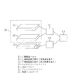
図1に、実施例による液晶表示素子の概略的な構成を示す。
実施例による液晶表示素子は、上側液晶表示素子(背景表示素子)30、下側液晶表示素子(表示部表示素子)40、マルチカラーバックライト50、LCDドライバ61、バックライトドライバ62、及び同期コントローラ63を含んで構成される。
FIG. 1 shows a schematic configuration of a liquid crystal display device according to an embodiment.
The liquid crystal display element according to the embodiment includes an upper liquid crystal display element (background display element) 30, a lower liquid crystal display element (display unit display element) 40, a
2層構造パネル20は、上側液晶表示素子30、及び下側液晶表示素子40を含んで構成される。マルチカラーバックライト50は、2層構造パネル20(下側液晶表示素子40)の下方に配置される。マルチカラーバックライト50は、複数の色、たとえば赤(R)、緑(G)、青(B)の光を発光可能なバックライトである。たとえば、CCFL、無機LED、有機LEDなどを光源として使用することができる。
The two-
LCDドライバ61は、上側液晶表示素子30及び下側液晶表示素子40を駆動する。バックライトドライバ62は、マルチカラーバックライト50を駆動する。同期コントローラ63は、LCDドライバ61とバックライトドライバ62とが同期して駆動するように、同期信号を与える。
The
上側液晶表示素子30及び下側液晶表示素子40は、たとえばともにノーマリホワイトの液晶表示素子である。
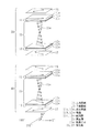
図2は、2層構造パネル20の一例を示す概略的な分解斜視図である。本図には、上側液晶表示素子30及び下側液晶表示素子40が、ともにノーマリホワイトの液晶表示素子である場合の構成例を示す。上側及び下側液晶表示素子30,40は、たとえばともに、電圧無印加時の液晶層のリタデーションが、Gooch&Tarryの第1ミニマム値に設定された、ツイストネマチック(twisted nematic;TN)モードの液晶表示素子である。
The upper liquid
FIG. 2 is a schematic exploded perspective view showing an example of the two-
上側液晶表示素子30は、上側基板11、上側基板11に略平行に対向配置される下側基板12、上側基板11と下側基板12との間に保持される液晶層15、及び偏光板16、17を含んで構成される。液晶層15には、90°のねじれ角を有するTN液晶である液晶分子15aが充填されている。
The upper liquid
上側基板11は、たとえば平板なガラス基板である透明基板11a、透明基板11a上にたとえばITO(indium tin oxide)等の透明導電材で形成された電極11b、及び電極11b上に形成された配向膜11cを含む。
The
下側基板12は、透明基板12a、透明基板12a上に形成された電極12b、及び電極12b上に形成された配向膜12cを含む。透明基板12a、電極12b及び配向膜12cを形成する材料は、上側基板11と同じでよい。
The
上側基板11と下側基板12とは、配向膜11c、12cが向き合うように対向配置される。
図2における右方向を基準(0°)とし、下側基板12と平行な面内において反時計回りに回転した方位角θで液晶分子の配向方向(長軸方向)等を表す角度座標を定義する。
The
2 is defined as an angle coordinate that represents the orientation direction (major axis direction) of liquid crystal molecules with an azimuth angle θ rotated counterclockwise in a plane parallel to the
上側基板11及び下側基板12の配向膜11c、12cには、ラビング処理が施されている。上側基板11の配向膜11cに施されたラビングの方向は方位角45°の方向であり、下側基板12の配向膜12cに施されたラビングの方向は方位角315°(−45°)の方向である。配向膜11c、12cに接触する液晶分子15aはラビング方向に平行に配向し、ラビング方向を示す矢印の先端側の端部が基板から持ち上がるようにチルトする。配向膜は対向配置されているので、下側基板12側の液晶分子15aの基板から持ち上がった方の端部が、上側基板11側の液晶分子15aの基板に接触する方の端部に対応するようにチルトする。
The
液晶層15内の液晶分子15aが方位角方向にツイストし、ヘリカル構造を構成する。このヘリカル構造は左旋回となり、ねじれ角(ツイスト角、旋回角)は90°、厚さ方向の中央に位置する液晶分子の配向方向の方位角θは270°になる。
The liquid crystal molecules 15a in the
偏光板16が、上側基板11の外側の面に密着し、偏光板17が、下側基板12の外側の面に密着している。偏光板16の透過軸(矢印でその方向を示す。)の方位角は45°であり、偏光板17の透過軸(矢印でその方向を示す。)の方位角は135°である。偏光板16と17とは、クロスニコル配置されている。
The
電圧が印加されない状態では、液晶分子15aはTN配列している。偏光板17を透過して下側基板12に入射した光は、液晶分子15aのダイレクタに沿って偏光方向を旋回させながら液晶層15内を進み、90°旋回させたところで上側基板11から出射するため、上側基板11側の偏光板16を透過する。このため「明」表示が実現される。
In a state where no voltage is applied, the liquid crystal molecules 15a are TN aligned. The light transmitted through the
電圧印加時においては、液晶分子15aが基板(上側基板11及び下側基板12)に垂直に立つため、偏光板17を透過して下側基板12に入射した光は、そのまま液晶層15内を進み、偏光板16で遮られる。この場合、「暗(黒)」表示が実現される。このように、上側液晶表示素子30は、ノーマリホワイトタイプの液晶表示素子である。
When a voltage is applied, the liquid crystal molecules 15a stand perpendicular to the substrates (the
なお、電圧無印加時の液晶層15のリタデーションを、Gooch&Tarryの第1ミニマム値に設定することで、電圧印加時に良好な黒レベルを得ることができる。
上側液晶表示素子30と下側液晶表示素子40とは、たとえば類似の構造を備えるが、電極の構造において相違する。この点については、後に詳述する。また、上側及び下側偏光板16、17の透過軸の方向が異なっている。下側液晶表示素子40については、上側偏光板16の透過軸の方向は、135°方向であり、下側偏光板17の透過軸の方向は45°方向である。
In addition, a favorable black level can be obtained at the time of voltage application by setting the retardation of the
The upper liquid
上側液晶表示素子30の下側偏光板17の透過軸と、下側液晶表示素子40の上側偏光板16の透過軸とは平行であるため、この2枚の偏光板のうちの一方を省くことも可能である。たとえば、下側液晶表示素子40の偏光板16を省いた場合、上側液晶表示素子30の偏光板17は、上側液晶表示素子30の構成要素であるとともに、下側液晶表示素子40の構成要素であるとも考える。
Since the transmission axis of the lower
なお、図示の2層構造パネル20は、全体としてノーマリホワイトタイプである。
2層構造パネル20の上側及び下側液晶表示素子30,40は、様々なタイプの素子の組み合わせで構成することが可能である。
The illustrated two-
The upper and lower liquid
図3(A)及び(B)を用いて、2層構造パネル20の上側及び下側液晶表示素子30,40の組み合わせについて説明する。
図3(A)は、上側及び下側液晶表示素子30,40がそれぞれ2枚の偏光板16,17を含む、偏光板4枚構成の2層構造パネル20を示し、図3(B)は、図3(A)の構成から、下側液晶表示素子40の偏光板16を省いて、上側液晶表示素子30の偏光板17を、上側液晶表示素子30の構成要素であるとともに、下側液晶表示素子40の構成要素であるとした、偏光板3枚構成の2層構造パネル20を示す。
A combination of the upper and lower liquid
FIG. 3A shows a two-
なお、図3(A)及び(B)においても、図2と同様に、下側基板12と平行な面内において角度座標を定義する。本図においては、右方向が0°方向、左方向が180°方向、紙面奥方向が90°方向、紙面手前方向が270°方向である。
3A and 3B, the angle coordinates are defined in a plane parallel to the
以下、観察者が、270°方位から観察する場合について述べる。
図3(A)を参照する。図3(A)は、図2に示したように、ノーマリホワイトTN液晶表示素子を2つ重ねたような形態である。上側及び下側液晶表示素子30,40の配置は任意ではあるが、上下の素子が重なる面に配置された偏光板16,17の透過軸の方向が平行である場合に、光利用効率は有利になるため、偏光板16,17の透過軸方位の好ましい設定や、上側及び下側液晶表示素子30,40の液晶層15の中央分子の好ましい配向方向が決まることになる。上側及び下側液晶表示素子30,40の液晶層15の中央分子の配向方向は、ともに215°〜315°であることが望ましく、両者を等しく270°とするのが最良である。
Hereinafter, a case where the observer observes from a 270 ° azimuth will be described.
Reference is made to FIG. FIG. 3A shows a form in which two normally white TN liquid crystal display elements are stacked as shown in FIG. The arrangement of the upper and lower liquid
図3(B)を参照する。図3(B)は、上側及び下側液晶表示素子30,40の液晶層15の中央分子の配向方向が等しく270°である場合、上下の素子が重なる面に配置される偏光板を1枚とした態様である。
Reference is made to FIG. FIG. 3B shows one polarizing plate disposed on the surface where the upper and lower elements overlap when the orientation directions of the central molecules of the
なお、図3(A)及び(B)に示す2層構造パネル20中の上側及び下側液晶表示素子30,40のTN液晶層15の液晶分子のねじれ角は、たとえばともに70°〜130°、たとえば両者等しく90°である。上側及び下側液晶表示素子30,40の液晶分子のねじれ角を一致させる必要はないが、両者を等しくした場合、動作させる上で便宜である。ただし、ねじれ方向を揃える必要はない。
The twist angles of the liquid crystal molecules of the TN
なお、上側及び下側液晶表示素子30,40は、TNタイプに限らず、たとえばノーマリホワイト表示が可能な複屈折制御(electrically controlled birefringence;ECB)型液晶表示素子の組み合わせでもよい。
The upper and lower liquid
図4(A)及び(B)は、それぞれ下側液晶表示素子(表示部表示素子)40及び上側液晶表示素子(背景表示素子)30の電極パタンの一部を示す概略的な平面図である。電極パタンと表示パタンとは対応するので、各電極部と各表示部とは対応する。本図には、電極部に斜線を付して示した。 4A and 4B are schematic plan views showing a part of electrode patterns of the lower liquid crystal display element (display unit display element) 40 and the upper liquid crystal display element (background display element) 30, respectively. . Since the electrode pattern corresponds to the display pattern, each electrode unit corresponds to each display unit. In this figure, the electrode portions are shown with diagonal lines.
図4(A)を参照する。下側液晶表示素子40は、表示部(文字部)を表示するために用いられる。このため、電極パタンも文字パタンに対応して形成される。下側液晶表示素子40の電極は、たとえば「0」〜「9」の10文字を表示することのできる7セグメント電極の電極部21〜27を有する。
Reference is made to FIG. The lower liquid
図4(B)を参照する。上側液晶表示素子30は、背景を表示するために用いられる。このため、電極パタンも背景パタン(文字パタンの反転パタン)に対応して形成される。上側液晶表示素子30の電極は、たとえば「0」〜「9」の10文字を表示することのできる7セグメント電極の電極部21〜27の反転パタンを全駆動できるように配線した電極構造を有する。本図には、その一部として電極部28を示した。
Reference is made to FIG. The upper liquid
2層構造パネル20は、図2や図3(A)及び(B)に示したように、上側と下側の2つの液晶表示素子で構成しなくとも、2層構造の液晶表示素子を用いて構成することもできる。この場合、2層セル構造でノーマリブラック型になる液晶セルを用いる。
As shown in FIG. 2 and FIGS. 3A and 3B, the two-
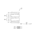
図5は、2層セル構造の液晶表示素子を用いて構成された2層構造パネル20を示す概略図である。なお、本図においても、図3(A)及び(B)と同様に角度座標を定義してある。以下、図3(A)及び(B)を参照して説明した場合と同様に、観察者が、270°方位から観察する場合について述べる。
FIG. 5 is a schematic view showing a two-
2層構造パネル20は、上側液晶セル30a、下側液晶セル40a、上側液晶セル30a側の偏光板16、及び下側液晶セル40a側の偏光板17を含んで構成される。
上側及び下側液晶セル30a、40aは、たとえばともにTN型の液晶セルである。両セル30a、40aの液晶層15の液晶分子は、同じ大きさで逆方向のねじれ角を有する。ねじれ角は、たとえば70°〜130°である。上側液晶セル30aの液晶層15の液晶分子は、たとえば右回りに90°のねじれ角を有し、下側液晶セル40aのそれは、たとえば左回りに90°のねじれ角を有する。
The two-
The upper and lower liquid crystal cells 30a and 40a are both TN type liquid crystal cells, for example. The liquid crystal molecules of the
また、上側及び下側液晶セル30a、40aの液晶層15の中央分子の配向方位は直交している。上側液晶セル30aの液晶層15の中央分子の配向方位は180°〜360°、たとえば315°であり、下側液晶セル40aのそれは215°〜315°、たとえば225°である。
The orientation directions of the central molecules of the
上側液晶セル30aの下側基板12は、下側液晶セル40aの上側基板11に接触している。また、偏光板16が、上側液晶セル30aの上側基板11の外側の面に密着し、偏光板17が、下側液晶セル40aの下側基板12の外側の面に密着している。
The
このように、2層セル構造の液晶表示素子を用いて2層構造パネル20を構成することもできる。
なお、上側及び下側液晶セル30a、40aを、ともにECB型の液晶セル、たとえば垂直配向型の液晶セルで形成することもできる。この場合、上側及び下側液晶セル30a,40aの液晶層15の中央分子の配向方位は、たとえばともに90°と同じ方位とすることができる。また、両者は直交させてもよい。両者を直交させた場合、電圧無印加時における液晶分子の配向が、水平配向である場合であっても同様に機能する。
In this way, the two-
Both the upper and lower liquid crystal cells 30a and 40a can be formed of ECB type liquid crystal cells, for example, vertical alignment type liquid crystal cells. In this case, the orientation direction of the center molecule of the
なお、液晶セル内の片側基板に絶縁層を介した多層電極構造を形成すれば、2層セル構造を採用しなくても、1つの液晶セルを用いることで、図1に示す実施例による液晶表示素子と同様の動作を実現することができる。 If a multilayer electrode structure with an insulating layer is formed on one side substrate in the liquid crystal cell, the liquid crystal according to the embodiment shown in FIG. 1 can be obtained by using one liquid crystal cell without adopting the two-layer cell structure. Operation similar to that of the display element can be realized.
以下、本願発明者らが実際に行った、実施例による液晶表示素子の駆動方法について説明する。
当該駆動方法においては、上側液晶表示素子(背景表示素子)30、下側液晶表示素子(表示部表示素子)40の透光状態、遮光状態の制御、及びマルチカラーバックライト55の発光の制御を同期させて表示を行う。
Hereinafter, a method of driving the liquid crystal display element according to the embodiment actually performed by the inventors will be described.
In the driving method, the upper liquid crystal display element (background display element) 30 and the lower liquid crystal display element (display unit display element) 40 are controlled to transmit light, block light, and emit light from the
1フレーム中に背景表示用のサブフレームを設け、背景表示用サブフレームにおいては、背景部分の表示を行うことに加え、表示部(文字部)のうち表示に使用しない部分(たとえば、図4(A)に示す表示部21〜27を用いて「0」を表示する場合、表示部24は、その表示に使用しない部分である。)の表示を行う。そして、他のサブフレームにおいて、実際に表示を行う文字領域(前出の例においては、「0」を表示する表示部21〜23、及び25〜27)の表示を行う。
In one frame, a background display subframe is provided. In the background display subframe, in addition to displaying the background portion, a portion of the display portion (character portion) that is not used for display (for example, FIG. When “0” is displayed using the
このような駆動方法により、表示部における多色表示性能を維持しつつ、背景を任意に変化させたカラー表示が可能となり、良好な表示品質を実現することができる。なお、この駆動方法は、本願発明者らの先の提案(特開2005−070440号公報)による液晶表示素子の駆動方法と組み合わせることもできる。 With such a driving method, it is possible to perform color display with the background arbitrarily changed while maintaining multicolor display performance in the display unit, and it is possible to achieve good display quality. This driving method can be combined with the driving method of the liquid crystal display element according to the previous proposal of the present inventors (Japanese Patent Laid-Open No. 2005-070440).
以下に示す2つの駆動例は、2層構造パネル20が、(i)上側液晶表示素子(背景表示素子)30及び下側液晶表示素子(表示部表示素子)40が、ともにノーマリホワイトの液晶表示素子である場合、及び、(ii)2層セル構造を備え、全体としてノーマリブラックタイプの液晶表示素子である場合、の2つの場合における駆動例である。
In the following two driving examples, the two-
下側液晶表示素子(表示部表示素子)40及び上側液晶表示素子(背景表示素子)30は、それぞれ図4(A)及び(B)に示す、7セグメント表示の電極パタン及びその反転パタンを有するものを使用した。また、液晶の駆動方法としては、スタティック駆動を採用した。 The lower liquid crystal display element (display unit display element) 40 and the upper liquid crystal display element (background display element) 30 each have a 7-segment display electrode pattern and its inverted pattern shown in FIGS. 4 (A) and 4 (B), respectively. I used something. Further, static driving was adopted as a liquid crystal driving method.
図6に、以下の駆動例によって実現した表示を示す。赤で表示される領域を「R」、黄で表示される領域を「Y」、青で表示される領域を「B」で表している。すなわち、図4(A)及び(B)に示す表示部22、25、及び27を赤(R)で表示し、表示部21、23、及び26を黄(Y)で表示し、更に、表示部24及び28を青(B)で表示した。
FIG. 6 shows a display realized by the following driving example. An area displayed in red is represented by “R”, an area displayed in yellow is represented by “Y”, and an area displayed in blue is represented by “B”. That is, the
駆動例においては、16.5msの1フレーム期間を、5.5msの3つのサブフレーム期間に分割し、最初のサブフレーム期間(サブフレーム期間1)においては、バックライトから青色の光を発光した。また2番目のサブフレーム期間(サブフレーム期間2)においては、赤色の光を、3番目のサブフレーム期間(サブフレーム期間3)においては、黄色の光を発光した。 In the driving example, one frame period of 16.5 ms is divided into three subframe periods of 5.5 ms, and blue light is emitted from the backlight in the first subframe period (subframe period 1). . Further, red light was emitted in the second subframe period (subframe period 2), and yellow light was emitted in the third subframe period (subframe period 3).
1フレーム期間の時間は16.5msに限らず、人間の目にちらつきを与えない表示が実現されるように設定することができる。また、各サブフレーム期間は、等しい時間となるように分割したが、それには限定されない。 The time of one frame period is not limited to 16.5 ms, and it can be set so as to realize a display that does not flicker in human eyes. In addition, each subframe period is divided so as to be equal time, but is not limited thereto.
各表示領域(たとえば表示部21等のセグメント)において、光を透過させるサブフレームは高々1つとした。このため赤(R)、黄(Y)、青(B)による3色表示となるが、表示色は、サブフレーム期間の数を増加することで、増やすことが可能である。 In each display region (for example, a segment such as the display unit 21), the number of subframes that transmit light is at most one. For this reason, three-color display using red (R), yellow (Y), and blue (B) is performed, but the display color can be increased by increasing the number of subframe periods.
液晶表示素子への駆動電圧印加開始時間と、バックライト点灯開始時間との差(ブランク時間)は2.5msとした。ブランク時間は、これより長くすることもできる。ただ、その場合、同じ表示品質を確保するためには、バックライトの発光輝度を向上させる必要がある。 The difference (blank time) between the drive voltage application start time to the liquid crystal display element and the backlight lighting start time was 2.5 ms. The blanking time can be longer than this. However, in that case, in order to ensure the same display quality, it is necessary to improve the light emission luminance of the backlight.
以下の駆動例を示す表において、LCDの欄の「on」は、液晶層に5Vの駆動電圧を印加したことを示す。また、「off」は、電圧無印加状態(0V)を示す。したがって、たとえば、ノーマリホワイトモードの液晶表示素子の場合、「off」時に光を透過し、「on」時には、光を透過しない。 In the table showing the following driving examples, “on” in the column of LCD indicates that a driving voltage of 5 V is applied to the liquid crystal layer. “Off” indicates a voltage non-application state (0 V). Therefore, for example, in a normally white mode liquid crystal display element, light is transmitted when “off” and light is not transmitted when “on”.
図7は、第1の駆動例を示す表である。第1の駆動例においては、上側液晶表示素子30、下側液晶表示素子40ともに、ノーマリホワイトTNモードの液晶表示素子を用いて、図1に示す液晶表示素子を作製し、駆動実験を行った。作製した液晶表示素子の2層構造パネル20は、図3(B)に示す構成とした。また、上側及び下側液晶表示素子30、40の液晶層15の立ち上がり及び立ち下がり応答速度は、ともに2msとした。
FIG. 7 is a table showing a first driving example. In the first driving example, the upper liquid
表示部を表示する下側液晶表示素子の欄を参照する。
表示部21については、サブフレーム期間3のみ「off(透過)」である。このため、サブフレーム期間3のバックライト点灯色である「黄」が表示される。
Reference is made to the column of the lower liquid crystal display element for displaying the display section.
For the
表示部22については、サブフレーム期間2のみ「off(透過)」である。このため、サブフレーム期間2のバックライト点灯色である「赤」が表示される。
表示部23,24,25,26,27については、それぞれ順に、サブフレーム期間3,1,2,3,2のみ「off(透過)」であるため、「黄」、「青」、「赤」、「黄」
「赤」が表示される。
For the
Regarding the
“Red” is displayed.
背景を表示する上側液晶表示素子の欄を参照する。
表示部28について、サブフレーム期間1のみ「off(透過)」である。このため、サブフレーム期間1のバックライト点灯色である「青」が表示される。
Reference is made to the column of the upper liquid crystal display element for displaying the background.
For the
この結果、図6に示した態様の、背景部も含めたカラー表示を良好に行うことができた。
図8は、第2の駆動例を示す表である。第2の駆動例においては、図5に示した2層構造で動作するノーマリブラックタイプの液晶表示素子を用いて、図1に示す液晶表示素子を作製し、駆動実験を行った。
As a result, the color display including the background portion of the embodiment shown in FIG. 6 was successfully performed.
FIG. 8 is a table showing a second driving example. In the second driving example, the liquid crystal display element shown in FIG. 1 was manufactured using the normally black type liquid crystal display element operating in the two-layer structure shown in FIG.
上下液晶セルともに、垂直配向モードの液晶セルを用いた。上下2つのセルは直接重ね合わせ、その上下に(重ね合わせた2つのセルを挟むように)偏光板を貼り付けた。セルの上側に貼り付けた偏光板の透過軸の方向は45°方向、セルの下側に貼り付けた偏光板の透過軸の方向は135°方向とし、クロスニコル配置とした。 A vertical alignment mode liquid crystal cell was used for both the upper and lower liquid crystal cells. The upper and lower two cells were directly overlapped, and a polarizing plate was attached on the upper and lower sides (so that the two overlapped cells were sandwiched). The direction of the transmission axis of the polarizing plate attached on the upper side of the cell was 45 ° direction, the direction of the transmission axis of the polarizing plate attached on the lower side of the cell was 135 ° direction, and a crossed Nicol arrangement was adopted.
ノーマリブラックモードの液晶表示素子の場合、「on」時に光を透過し、「off」時には、光を透過しない。
したがって、下側液晶表示素子の、たとえば表示部21については、サブフレーム期間3のみ「on(透過)」であるため、サブフレーム期間3のバックライト点灯色である「黄」が表示される。
In the case of a normally black mode liquid crystal display element, light is transmitted when “on”, and light is not transmitted when “off”.
Accordingly, for the
また、上側液晶表示素子の表示部28については、サブフレーム期間1のみ「on(透過)」であるため、サブフレーム期間1のバックライト点灯色である「青」が表示される。
Further, since the
2層構造の液晶表示素子を用いた場合であっても、図6に示した態様の、背景部も含めたカラー表示を良好に行うことができた。
なお、本願発明者らは、ねじれ角が等しくねじれ方向が逆方向である2つのTNモードの液晶セルを上下セルとして採用し、それらを液晶層中央分子が相互に直交するように、重ね合わせたTNノーマリブラックモードの2層構造液晶表示素子を作製し、同様に駆動実験を行ったが、この場合にも図6に示した態様の、背景部も含めたカラー表示を良好に行うことができた。
Even when a liquid crystal display element having a two-layer structure was used, the color display including the background portion of the embodiment shown in FIG. 6 could be satisfactorily performed.
The inventors of the present invention adopted two TN-mode liquid crystal cells having the same twist angle and opposite twist directions as upper and lower cells, and stacked them so that the liquid crystal layer center molecules were orthogonal to each other. A TN normally black mode two-layer structure liquid crystal display element was manufactured and a driving experiment was conducted in the same manner. In this case as well, the color display including the background portion as shown in FIG. did it.
なお、本願発明者らは、液晶セルの応答速度が、立ち上がり、立ち下がりともに、20ms以下のパネルであれば、色表示が可能であることを確認した。これは、バックライトから出射された光の透過率が、およそ30%以下であっても色表示が可能であることを示す。 The inventors of the present application confirmed that color display is possible if the response speed of the liquid crystal cell is a panel of 20 ms or less, both rising and falling. This indicates that color display is possible even when the transmittance of light emitted from the backlight is approximately 30% or less.
以上、実施例に沿って本発明を説明したが、本発明はこれらに限定されるものではない。たとえば実施例においては、ノーマリブラックモード及びノーマリホワイトモードの液晶セルを用いたが、高速応答が可能な動作モードであれば、他の動作モードを用いてもよい。その他、種々の変更、改良、組み合わせ等が可能なことは当業者には自明であろう。 As mentioned above, although this invention was demonstrated along the Example, this invention is not limited to these. For example, in the embodiments, normally black mode and normally white mode liquid crystal cells are used, but other operation modes may be used as long as they are operation modes capable of high-speed response. It will be apparent to those skilled in the art that other various modifications, improvements, combinations, and the like are possible.
FS駆動を行う液晶表示素子全般に用いることができる。 It can be used for all liquid crystal display elements that perform FS driving.
11 上側基板
12 下側基板
11a,12a 透明基板
11b,12b 電極
11c,12c 配向膜
15 液晶層
15a 液晶分子
16,17 偏光板
20 2層構造パネル
21〜28 電極部(表示部)
30 上側液晶表示素子(背景表示素子)
30a 上側液晶セル
31 上側基板
32 下側基板
39 液晶層
39a 液晶分子
40 下側液晶表示素子(表示部表示素子)
40a 下側液晶セル
41 上側偏光板
42 下側偏光板
49 エリアカラーフィルタ
49r 赤色部
49g 緑色部
49b 青色部
49w 白色部
50 マルチカラーバックライト
51 ブラックマスク
52 白色バックライト
53 駆動回路
54 バックライト同期駆動回路
55 マルチカラーバックライト
61 LCDドライバ
62 バックライトドライバ
63 同期コントローラ
DESCRIPTION OF
30 Upper LCD display element (background display element)
30a Upper
40a Lower liquid crystal cell 41
Claims (7)
前記光源を出射した光が入射する第1の基板対と、
前記第1の基板対の対向する面上に形成され、第1のパタンを備える第1の電極と、
前記第1の基板対の対向する面の間に保持され、前記第1の電極を用いて電圧が印加されることで透光状態と遮光状態とを選択的に制御できる第1の液晶層と、
前記第1の基板対を出射した光が入射する第2の基板対と、
前記第2の基板対の対向する面上に形成され、前記第1のパタンの反転パタンである第2のパタンを備える第2の電極と、
前記第2の基板対の対向する面の間に保持され、前記第2の電極を用いて電圧が印加されることで透光状態と遮光状態とを選択的に制御できる第2の液晶層と、
前記第1の基板対の光入射面側に配置された第1の偏光板と、
前記第2の基板対の光出射面側に配置された第2の偏光板と、
前記第1の基板対の光出射面側に配置された第3の偏光板と、
前記第2の基板対の光入射面側に配置された第4の偏光板と、
1フレーム期間を複数のサブフレーム期間に時分割し、各サブフレーム期間内で前記光源を発光させ、その発光に同期させて、前記第1の液晶層及び第2の液晶層の透光状態と遮光状態を制御する制御装置と
を有し、
第1の液晶表示素子が、前記第1の基板対、前記第1の電極、前記第1の液晶層、前記第1の偏光板、及び前記第3の偏光板を含んで構成され、
第2の液晶表示素子が、前記第2の基板対、前記第2の電極、前記第2の液晶層、前記第2の偏光板、及び前記第4の偏光板を含んで構成され、
前記第1及び第2の液晶表示素子が、ともにノーマリホワイトの液晶表示素子であり、
表示部と背景部とが画定されたノーマリホワイトの液晶表示装置。 A light source capable of emitting multiple colors;
A first pair of substrates on which light emitted from the light source is incident;
A first electrode formed on opposing surfaces of the first pair of substrates and comprising a first pattern;
A first liquid crystal layer that is held between opposing surfaces of the first pair of substrates and that can selectively control a light-transmitting state and a light-blocking state by applying a voltage using the first electrode; ,
A second substrate pair on which the light emitted from the first substrate pair enters;
A second electrode comprising a second pattern formed on opposite surfaces of the second pair of substrates, the second pattern being an inverted pattern of the first pattern;
A second liquid crystal layer that is held between opposing surfaces of the second pair of substrates and that can selectively control a light-transmitting state and a light-blocking state by applying a voltage using the second electrode; ,
A first polarizing plate disposed on the light incident surface side of the first substrate pair;
A second polarizing plate disposed on the light exit surface side of the second substrate pair;
A third polarizing plate disposed on the light exit surface side of the first substrate pair;
A fourth polarizing plate disposed on the light incident surface side of the second substrate pair;
One frame period is time-divided into a plurality of subframe periods, the light source is caused to emit light within each subframe period, and the light transmission states of the first liquid crystal layer and the second liquid crystal layer are synchronized with the light emission. A control device for controlling the light shielding state,
A first liquid crystal display element including the first substrate pair, the first electrode, the first liquid crystal layer, the first polarizing plate, and the third polarizing plate;
A second liquid crystal display element including the second substrate pair, the second electrode, the second liquid crystal layer, the second polarizing plate, and the fourth polarizing plate;
The first and second liquid crystal display elements are both normally white liquid crystal display elements,
A normally white liquid crystal display device in which a display portion and a background portion are defined.
前記光源を出射した光が入射する第1の基板対と、
前記第1の基板対の対向する面上に形成され、第1のパタンを備える第1の電極と、
前記第1の基板対の対向する面の間に保持され、前記第1の電極を用いて電圧が印加されることで透光状態と遮光状態とを選択的に制御できる第1の液晶層と、
前記第1の基板対を出射した光が入射する第2の基板対と、
前記第2の基板対の対向する面上に形成され、前記第1のパタンの反転パタンである第2のパタンを備える第2の電極と、
前記第2の基板対の対向する面の間に保持され、前記第2の電極を用いて電圧が印加されることで透光状態と遮光状態とを選択的に制御できる第2の液晶層と、
前記第1の基板対の光入射面側に配置された第1の偏光板と、
前記第2の基板対の光出射面側に配置された第2の偏光板と、
前記第1の基板対と前記第2の基板対との間に配置された第3の偏光板と、
1フレーム期間を複数のサブフレーム期間に時分割し、各サブフレーム期間内で前記光源を発光させ、その発光に同期させて、前記第1の液晶層及び第2の液晶層の透光状態と遮光状態を制御する制御装置と
を有し、
第1の液晶表示素子が、前記第1の基板対、前記第1の電極、前記第1の液晶層、前記第1の偏光板、及び前記第3の偏光板を含んで構成され、
第2の液晶表示素子が、前記第2の基板対、前記第2の電極、前記第2の液晶層、前記第2の偏光板、及び前記第3の偏光板を含んで構成され、
前記第1及び第2の液晶表示素子が、ともにノーマリホワイトの液晶表示素子であり、
表示部と背景部とが画定された液晶表示装置。 A light source capable of emitting multiple colors;
A first pair of substrates on which light emitted from the light source is incident;
A first electrode formed on opposing surfaces of the first pair of substrates and comprising a first pattern;
A first liquid crystal layer that is held between opposing surfaces of the first pair of substrates and that can selectively control a light-transmitting state and a light-blocking state by applying a voltage using the first electrode; ,
A second substrate pair on which the light emitted from the first substrate pair enters;
A second electrode comprising a second pattern formed on opposite surfaces of the second pair of substrates, the second pattern being an inverted pattern of the first pattern;
A second liquid crystal layer that is held between opposing surfaces of the second pair of substrates and that can selectively control a light-transmitting state and a light-blocking state by applying a voltage using the second electrode; ,
A first polarizing plate disposed on the light incident surface side of the first substrate pair;
A second polarizing plate disposed on the light exit surface side of the second substrate pair;
A third polarizing plate disposed between the first substrate pair and the second substrate pair;
One frame period is time-divided into a plurality of subframe periods, the light source is caused to emit light within each subframe period, and the light transmission states of the first liquid crystal layer and the second liquid crystal layer are synchronized with the light emission. A control device for controlling the light shielding state,
A first liquid crystal display element including the first substrate pair, the first electrode, the first liquid crystal layer, the first polarizing plate, and the third polarizing plate;
A second liquid crystal display element including the second substrate pair, the second electrode, the second liquid crystal layer, the second polarizing plate, and the third polarizing plate;
The first and second liquid crystal display elements are both normally white liquid crystal display elements,
A liquid crystal display device in which a display portion and a background portion are defined.
第1の液晶セルであって、
前記光源を出射した光が入射する第1の基板対と、
前記第1の基板対の対向する面上に形成され、第1のパタンを備える第1の電極と、
前記第1の基板対の対向する面の間に保持され、前記第1の電極を用いて電圧が印加されることで透光状態と遮光状態とを選択的に制御できる第1の液晶層と、
を含む、ECB型の第1の液晶セルと、
第2の液晶セルであって、
前記第1の基板対を出射した光が入射する第2の基板対と、
前記第2の基板対の対向する面上に形成され、前記第1のパタンの反転パタンである第2のパタンを備える第2の電極と、
前記第2の基板対の対向する面の間に保持され、前記第2の電極を用いて電圧が印加されることで透光状態と遮光状態とを選択的に制御できる第2の液晶層と、
を含む、ECB型の第2の液晶セルと、
前記第1の基板対の光入射面側に配置された第1の偏光板と、
前記第2の基板対の光出射面側に配置された第2の偏光板と、
1フレーム期間を複数のサブフレーム期間に時分割し、各サブフレーム期間内で前記光源を発光させ、その発光に同期させて、前記第1の液晶層及び第2の液晶層の透光状態と遮光状態を制御する制御装置と
を有し、
前記第1の液晶層と、前記第2の液晶層の中央分子の配向方位が直交し、かつ、前記第1の偏光板と前記第2の偏光板とが、全体としてノーマリブラックとなるように配置され、
表示部と背景部とが画定された液晶表示装置。 A light source capable of emitting multiple colors;
A first liquid crystal cell,
A first pair of substrates on which light emitted from the light source is incident;
A first electrode formed on opposing surfaces of the first pair of substrates and comprising a first pattern;
A first liquid crystal layer that is held between opposing surfaces of the first pair of substrates and that can selectively control a light-transmitting state and a light-blocking state by applying a voltage using the first electrode; ,
An ECB-type first liquid crystal cell including:
A second liquid crystal cell,
A second substrate pair on which the light emitted from the first substrate pair enters;
A second electrode comprising a second pattern formed on opposite surfaces of the second pair of substrates, the second pattern being an inverted pattern of the first pattern;
A second liquid crystal layer that is held between opposing surfaces of the second pair of substrates and that can selectively control a light-transmitting state and a light-blocking state by applying a voltage using the second electrode; ,
An ECB-type second liquid crystal cell including:
A first polarizing plate disposed on the light incident surface side of the first substrate pair;
A second polarizing plate disposed on the light exit surface side of the second substrate pair;
One frame period is time-divided into a plurality of subframe periods, the light source is caused to emit light within each subframe period, and the light transmission states of the first liquid crystal layer and the second liquid crystal layer are synchronized with the light emission. A control device for controlling the light shielding state,
The first liquid crystal layer and the second liquid crystal layer have orthogonal orientations of central molecules, and the first polarizing plate and the second polarizing plate are normally black as a whole. Placed in
A liquid crystal display device in which a display portion and a background portion are defined.
前記光源を出射した光が入射する第1の基板対と、
前記第1の基板対の対向する面上に形成され、第1のパタンを備える第1の電極と、
前記第1の基板対の対向する面の間に保持され、前記第1の電極を用いて電圧が印加されることで透光状態と遮光状態とを選択的に制御できる第1の液晶層と、
前記光源を出射した光が入射する第2の基板対と、
前記第2の基板対の対向する面上に形成され、前記第1のパタンの反転パタンである第2のパタンを備える第2の電極と、
前記第2の基板対の対向する面の間に保持され、前記第2の電極を用いて電圧が印加されることで透光状態と遮光状態とを選択的に制御できる第2の液晶層と、
前記第1及び第2の基板対の光入射面側に配置された第1の偏光板と、
前記第1及び第2の基板対の光出射面側に配置された第2の偏光板と、
1フレーム期間を複数のサブフレーム期間に時分割し、各サブフレーム期間内で前記光源を発光させ、その発光に同期させて、前記第1の液晶層及び第2の液晶層の透光状態と遮光状態を制御する制御装置と
を有し、
前記第1の基板対の対向する一面上に形成され、前記第1のパタンを備える前記第1の電極の一部を構成する第3の電極と、
前記第1の基板対の対向する他面上に形成され、前記第1のパタンを備える前記第1の電極の他部を構成する第4の電極と、
前記第2の基板対の対向する一面上に形成され、前記第2のパタンを備える前記第2の電極の一部を構成する第5の電極と、
前記第2の基板対の対向する他面上に形成され、前記第2のパタンを備える前記第2の電極の他部を構成する第6の電極と
を含み、
前記第1の基板対と前記第2の基板対が同一の基板対であり、
前記第1の液晶層と前記第2の液晶層が同一の液晶層であり、
前記第3の電極と前記第5の電極が絶縁膜を介して多層化され、同一とされた前記第1の基板対と前記第2の基板対の一方の片側基板に形成されており、
前記第4の電極と前記第6の電極が絶縁膜を介して多層化され、同一とされた前記第1の基板対と前記第2の基板対の他方の片側基板に形成されており、
表示部と背景部とが画定された液晶表示装置。 A light source capable of emitting multiple colors;
A first pair of substrates on which light emitted from the light source is incident;
A first electrode formed on opposing surfaces of the first pair of substrates and comprising a first pattern;
A first liquid crystal layer that is held between opposing surfaces of the first pair of substrates and that can selectively control a light-transmitting state and a light-blocking state by applying a voltage using the first electrode; ,
A second substrate pair on which light emitted from the light source is incident;
A second electrode comprising a second pattern formed on opposite surfaces of the second pair of substrates, the second pattern being an inverted pattern of the first pattern;
A second liquid crystal layer that is held between opposing surfaces of the second pair of substrates and that can selectively control a light-transmitting state and a light-blocking state by applying a voltage using the second electrode; ,
A first polarizing plate disposed on the light incident surface side of the first and second substrate pairs;
A second polarizing plate disposed on the light exit surface side of the first and second substrate pairs;
One frame period is time-divided into a plurality of subframe periods, the light source is caused to emit light within each subframe period, and the light transmission states of the first liquid crystal layer and the second liquid crystal layer are synchronized with the light emission. A control device for controlling the light shielding state,
A third electrode that is formed on one opposing surface of the first substrate pair and that constitutes a part of the first electrode comprising the first pattern;
A fourth electrode forming the other part of the first electrode, which is formed on the other opposite surface of the first substrate pair, and includes the first pattern;
A fifth electrode that is formed on one opposing surface of the second substrate pair and forms a part of the second electrode including the second pattern;
A sixth electrode which is formed on the other opposing surface of the second substrate pair and which constitutes the other part of the second electrode provided with the second pattern;
Including
The first substrate pair and the second substrate pair are the same substrate pair;
The first liquid crystal layer and the second liquid crystal layer are the same liquid crystal layer;
The third electrode and the fifth electrode are multilayered via an insulating film, and are formed on one side substrate of the first substrate pair and the second substrate pair that are the same,
The fourth electrode and the sixth electrode are multilayered via an insulating film, and are formed on the other one-side substrate of the first substrate pair and the second substrate pair,
A liquid crystal display device in which a display portion and a background portion are defined.
Priority Applications (2)
| Application Number | Priority Date | Filing Date | Title |
|---|---|---|---|
| JP2005157727A JP4688143B2 (en) | 2005-05-30 | 2005-05-30 | Liquid crystal display |
| CN2006100850266A CN1873502B (en) | 2005-05-30 | 2006-05-30 | Liquid crystal display device |
Applications Claiming Priority (1)
| Application Number | Priority Date | Filing Date | Title |
|---|---|---|---|
| JP2005157727A JP4688143B2 (en) | 2005-05-30 | 2005-05-30 | Liquid crystal display |
Publications (2)
| Publication Number | Publication Date |
|---|---|
| JP2006330612A JP2006330612A (en) | 2006-12-07 |
| JP4688143B2 true JP4688143B2 (en) | 2011-05-25 |
Family
ID=37484013
Family Applications (1)
| Application Number | Title | Priority Date | Filing Date |
|---|---|---|---|
| JP2005157727A Expired - Fee Related JP4688143B2 (en) | 2005-05-30 | 2005-05-30 | Liquid crystal display |
Country Status (2)
| Country | Link |
|---|---|
| JP (1) | JP4688143B2 (en) |
| CN (1) | CN1873502B (en) |
Families Citing this family (11)
| Publication number | Priority date | Publication date | Assignee | Title |
|---|---|---|---|---|
| JP5052170B2 (en) * | 2007-03-15 | 2012-10-17 | スタンレー電気株式会社 | Liquid crystal display element, projection display device using the same, and driving method thereof |
| JP5052933B2 (en) * | 2007-03-29 | 2012-10-17 | スタンレー電気株式会社 | Liquid crystal display element, projection display device using the same, and driving method thereof |
| JP5283850B2 (en) * | 2007-03-07 | 2013-09-04 | スタンレー電気株式会社 | Liquid crystal display device and driving method thereof |
| JP5655205B2 (en) * | 2008-03-24 | 2015-01-21 | ソニー株式会社 | Liquid crystal display device and liquid crystal display method, and display control device and display control method |
| JP5192302B2 (en) * | 2008-07-04 | 2013-05-08 | スタンレー電気株式会社 | Liquid crystal display |
| JP2010266746A (en) * | 2009-05-15 | 2010-11-25 | Stanley Electric Co Ltd | Liquid crystal display device |
| CN105278132A (en) * | 2014-05-28 | 2016-01-27 | 台湾巴可科技股份有限公司 | Matrix circuit board and method for manufacturing display device |
| US10216034B2 (en) * | 2014-06-13 | 2019-02-26 | Sharp Kabushiki Kaisha | Liquid crystal display device |
| KR102630610B1 (en) * | 2016-12-26 | 2024-01-26 | 엘지디스플레이 주식회사 | Multi layer display device and method for driving the same |
| CN107942575B (en) * | 2017-11-22 | 2021-05-04 | 樊子健 | Display system of multilayer TN-LCD |
| CN109147699B (en) * | 2018-09-19 | 2021-01-22 | 京东方科技集团股份有限公司 | Double-layer display device and driving method thereof |
Citations (1)
| Publication number | Priority date | Publication date | Assignee | Title |
|---|---|---|---|---|
| JP2005070440A (en) * | 2003-08-25 | 2005-03-17 | Stanley Electric Co Ltd | Liquid crystal display element and method for driving same |
Family Cites Families (10)
| Publication number | Priority date | Publication date | Assignee | Title |
|---|---|---|---|---|
| JPS58138975U (en) * | 1981-11-20 | 1983-09-19 | リコーエレメックス株式会社 | display device |
| JPS61107380A (en) * | 1984-10-31 | 1986-05-26 | 日本精機株式会社 | Liquid crystal display unit |
| JPS62176830U (en) * | 1986-04-28 | 1987-11-10 | ||
| JPS63247728A (en) * | 1987-04-03 | 1988-10-14 | Hitachi Ltd | Liquid crystal display element |
| JPH0793562B2 (en) * | 1987-07-27 | 1995-10-09 | 日本電気アイシーマイコンシステム株式会社 | Output buffer circuit |
| BR9811721A (en) * | 1997-08-01 | 2000-09-26 | Citizen Watch Co Ltd | Liquid crystal indicator panel for clock |
| DE69806573T2 (en) * | 1997-11-28 | 2002-12-19 | Citizen Watch Co Ltd | LIQUID CRYSTAL DISPLAY DEVICE AND CONTROL METHOD THEREFOR |
| EP0959452A3 (en) * | 1998-05-23 | 1999-12-22 | Mannesmann VDO Aktiengesellschaft | Method of displaying variable information |
| JP2000347156A (en) * | 1999-06-02 | 2000-12-15 | Rohm Co Ltd | Liquid crystal display element |
| TW546555B (en) * | 2000-05-16 | 2003-08-11 | Asulab Sa | Display assembly with chromatic contrast inversion |
-
2005
- 2005-05-30 JP JP2005157727A patent/JP4688143B2/en not_active Expired - Fee Related
-
2006
- 2006-05-30 CN CN2006100850266A patent/CN1873502B/en not_active Expired - Fee Related
Patent Citations (1)
| Publication number | Priority date | Publication date | Assignee | Title |
|---|---|---|---|---|
| JP2005070440A (en) * | 2003-08-25 | 2005-03-17 | Stanley Electric Co Ltd | Liquid crystal display element and method for driving same |
Also Published As
| Publication number | Publication date |
|---|---|
| CN1873502A (en) | 2006-12-06 |
| JP2006330612A (en) | 2006-12-07 |
| CN1873502B (en) | 2010-04-14 |
Similar Documents
| Publication | Publication Date | Title |
|---|---|---|
| JP4688143B2 (en) | Liquid crystal display | |
| KR100478804B1 (en) | Optical shifter and optical display system | |
| JPWO2007043148A1 (en) | Liquid crystal display device and display method | |
| US20080084521A1 (en) | Field sequentially driven liquid crystal display device | |
| JP2005301026A (en) | Color liquid crystal display and its display method | |
| JP2009063878A (en) | Liquid crystal display device | |
| JP2005078070A (en) | Structure of display capable of making both side display and driving method for the same | |
| JP5096848B2 (en) | Liquid crystal display | |
| JP2008096481A (en) | Field sequential liquid crystal display device | |
| KR100840204B1 (en) | Liquid crystal display and driving method thereof | |
| WO2008063171A2 (en) | Dual mode display | |
| JP2003131191A (en) | Field sequential color liquid crystal display device | |
| JP5138893B2 (en) | Liquid crystal display element and method for driving liquid crystal display element | |
| JP2009115963A (en) | Liquid crystal display device and its driving method | |
| TWI401496B (en) | Transflective display with white tuning | |
| JP5349773B2 (en) | Liquid crystal display | |
| JP4884040B2 (en) | Liquid crystal display element and method for driving liquid crystal display element | |
| JP5192302B2 (en) | Liquid crystal display | |
| JP5274052B2 (en) | Liquid crystal display | |
| JP5106777B2 (en) | Liquid crystal display element and method for driving liquid crystal display element | |
| JP5052933B2 (en) | Liquid crystal display element, projection display device using the same, and driving method thereof | |
| JP5052170B2 (en) | Liquid crystal display element, projection display device using the same, and driving method thereof | |
| JP3195653B2 (en) | Flat display panel | |
| JP5283850B2 (en) | Liquid crystal display device and driving method thereof | |
| JP5058648B2 (en) | Liquid crystal display element |
Legal Events
| Date | Code | Title | Description |
|---|---|---|---|
| A621 | Written request for application examination |
Free format text: JAPANESE INTERMEDIATE CODE: A621 Effective date: 20080428 |
|
| A977 | Report on retrieval |
Free format text: JAPANESE INTERMEDIATE CODE: A971007 Effective date: 20100802 |
|
| A131 | Notification of reasons for refusal |
Free format text: JAPANESE INTERMEDIATE CODE: A131 Effective date: 20100817 |
|
| A521 | Written amendment |
Free format text: JAPANESE INTERMEDIATE CODE: A523 Effective date: 20101007 |
|
| A131 | Notification of reasons for refusal |
Free format text: JAPANESE INTERMEDIATE CODE: A131 Effective date: 20101109 |
|
| A521 | Written amendment |
Free format text: JAPANESE INTERMEDIATE CODE: A523 Effective date: 20110107 |
|
| TRDD | Decision of grant or rejection written | ||
| A01 | Written decision to grant a patent or to grant a registration (utility model) |
Free format text: JAPANESE INTERMEDIATE CODE: A01 Effective date: 20110208 |
|
| A01 | Written decision to grant a patent or to grant a registration (utility model) |
Free format text: JAPANESE INTERMEDIATE CODE: A01 |
|
| A61 | First payment of annual fees (during grant procedure) |
Free format text: JAPANESE INTERMEDIATE CODE: A61 Effective date: 20110210 |
|
| R150 | Certificate of patent or registration of utility model |
Ref document number: 4688143 Country of ref document: JP Free format text: JAPANESE INTERMEDIATE CODE: R150 Free format text: JAPANESE INTERMEDIATE CODE: R150 |
|
| FPAY | Renewal fee payment (event date is renewal date of database) |
Free format text: PAYMENT UNTIL: 20140225 Year of fee payment: 3 |
|
| R250 | Receipt of annual fees |
Free format text: JAPANESE INTERMEDIATE CODE: R250 |
|
| R250 | Receipt of annual fees |
Free format text: JAPANESE INTERMEDIATE CODE: R250 |
|
| R250 | Receipt of annual fees |
Free format text: JAPANESE INTERMEDIATE CODE: R250 |
|
| R250 | Receipt of annual fees |
Free format text: JAPANESE INTERMEDIATE CODE: R250 |
|
| R250 | Receipt of annual fees |
Free format text: JAPANESE INTERMEDIATE CODE: R250 |
|
| R250 | Receipt of annual fees |
Free format text: JAPANESE INTERMEDIATE CODE: R250 |
|
| LAPS | Cancellation because of no payment of annual fees |