JP4686366B2 - Sliding door energizer - Google Patents
Sliding door energizer Download PDFInfo
- Publication number
- JP4686366B2 JP4686366B2 JP2006006327A JP2006006327A JP4686366B2 JP 4686366 B2 JP4686366 B2 JP 4686366B2 JP 2006006327 A JP2006006327 A JP 2006006327A JP 2006006327 A JP2006006327 A JP 2006006327A JP 4686366 B2 JP4686366 B2 JP 4686366B2
- Authority
- JP
- Japan
- Prior art keywords
- sliding door
- cable
- reel
- casing
- frame
- Prior art date
- Legal status (The legal status is an assumption and is not a legal conclusion. Google has not performed a legal analysis and makes no representation as to the accuracy of the status listed.)
- Expired - Fee Related
Links
Images




Landscapes
- Power-Operated Mechanisms For Wings (AREA)
Description
本発明は、移動自在な引戸に取り付けられる電気錠等の電気機器に、信号電流を建物側の建具枠から供給する引戸用通電装置に関する。 The present invention relates to a sliding door energization device for supplying a signal current from a fitting frame on a building side to an electric device such as an electric lock attached to a movable sliding door.
従来から、施解錠を電気錠によって行うようにした引戸がある。この種の引戸は、電気錠にリード線を介して給電する関係上、電気錠等の電気機器が建物側である固定建具枠に取り付けられ、受金具が引戸側に取り付けるようになっている。これら装置であっても固定建具枠側に電気錠を取り付ける余裕がある場合は何ら問題はないが、固定建具枠側に取り付ける余裕がない場合には、移動体側の引戸に電気錠を取り付けなければならず、それに伴い固定建具枠側から引戸側に給電する必要が生じる。 Conventionally, there is a sliding door in which locking / unlocking is performed by an electric lock. In this type of sliding door, an electric device such as an electric lock is attached to a fixed fitting frame on the building side, and a receiving metal fitting is attached to the sliding door side because power is supplied to the electric lock through a lead wire. Even with these devices, there is no problem if there is room to attach the electric lock to the fixed fitting frame side, but if there is no room to attach to the fixed fitting frame side, the electric lock must be attached to the sliding door on the moving body side. Accordingly, it is necessary to supply power from the fixed fixture frame side to the sliding door side.
引戸のように移動する物体に固定側から給電する引戸用通電装置としては、例えば特許文献1に開示される通電装置がある。この通電装置は、電気錠を備えた引戸の上部又は戸枠の何れか一方に可動接触体を、他方に固定接触体をそれぞれ設け、これら可動接触体と固定接触体とは電気錠、又は電源と接続したリード線と接続し、閉戸時には可動接触体と固定接触体とを接触させ通電可能にすると共に、固定接触体、或いは可動接触体の少なくとも一方を被覆するカバーを可動自在に且つ常時バネなどの付勢力によつて被覆する方向に付勢して設け、閉戸時にカバーが付勢力に抗して移動し、可動接触体と固定接触体とが接触するように構成している。この構成により、電気錠を取り付けた戸を開放しているときには、可動接触体が固定接触体より離間して接触していないことから、上側のリード線を介して固定接触体に加電していても、下側のリード線には通電されないため、施錠することはできない。一方、戸を完全に閉じると、可動接触体が、固定接触体に接触し、上側のリード線及び下側のリード線を介して電気錠に通電可能となり、通電の瞬間に電気錠が施錠される。 As a sliding door energization device that feeds power from a fixed side to a moving object such as a sliding door, for example, there is an energization device disclosed in Patent Document 1. In this energizing device, a movable contact body is provided on either the upper part of the sliding door or the door frame provided with the electric lock, and a fixed contact body is provided on the other, and the movable contact body and the fixed contact body are an electric lock or a power source. When the door is closed, the movable contact body and the fixed contact body are brought into contact with each other to enable energization, and the cover that covers at least one of the fixed contact body or the movable contact body can be moved freely and constantly. The cover is urged in a covering direction by an urging force such as a spring, and the cover moves against the urging force when the door is closed, and the movable contact body and the fixed contact body are in contact with each other. With this configuration, when the door to which the electric lock is attached is opened, the movable contact member is not in contact with the fixed contact member so that the fixed contact member is energized via the upper lead wire. However, since the lower lead wire is not energized, it cannot be locked. On the other hand, when the door is completely closed, the movable contact body comes into contact with the fixed contact body, and the electric lock can be energized via the upper lead wire and the lower lead wire, and the electric lock is locked at the moment of energization. The
また、引戸用通電装置には、特許文献2に開示される給電装置がある。この給電装置は、上枠上部にガイド部材を敷設し、同ガイド部材に案内されて左右摺動する複数のスライダーを設け、引戸に取り付けられた電気錠等の電気機器へ給電するためのケーブルを、引戸の最大移動距離で給電できる長さとし、複数のスライダーにケーブルを固着した構成としている。この構成により、引戸の移動につれてケーブルが牽引され、このケーブルの移動によってスライダーが摺動し、隣接するスライダー間でケーブルが延びたり、弛んだりするので、引戸の開放または閉鎖位置でケーブルが大きく垂れ下がったりせず、スパイラル線のようにコイルの外径が大きくなって、上枠の巾を大きくしなければならないようなことはない。
しかしながら、特許文献1に開示される通電装置は、引戸を閉鎖した時のみに通電を可能とする構成であるため、常時監視が行えないとともに、引戸の開状態の検出と、信号線の断線との区別がつかない問題があった。また、端子数が多いため、薄厚の引戸には対応が困難となった。また、特許文献2に開示される給電装置は、複数の配線を太い1本のケーブルとし、弛ませて接続するため、大きな収容スペースを例えば建物壁側等に確保しなければならず、装置が大型化するとともに、構造も複雑となる問題があった。また、この特許文献2に開示される給電装置は、引戸にケーブルが接続されるため、引戸の取り外しが容易に行えなくなり、メンテナンス性も低下する問題があった。 However, since the energization device disclosed in Patent Document 1 is configured to allow energization only when the sliding door is closed, it cannot be constantly monitored, and the detection of the open state of the sliding door and the disconnection of the signal line There was a problem that could not be distinguished. In addition, since the number of terminals is large, it is difficult to handle thin sliding doors. Moreover, since the electric power feeder disclosed by patent document 2 makes several wiring into one thick cable and connects it loosely, a large accommodation space must be ensured on the building wall side etc., and an apparatus is There is a problem that the structure becomes complicated as the size increases. In addition, since the power supply device disclosed in Patent Document 2 has a cable connected to the sliding door, there is a problem that the sliding door cannot be easily detached and the maintainability is also lowered.
本発明は上記状況に鑑みてなされたもので、その第1の目的は、簡素な構造で、常時接続のコンパクトな引戸用通電装置を提供し、もって、常時監視を可能にし、簡単な後付施工を可能にすることにある。また、その第2の目的は、引戸の建具枠からの取り外しが容易な引戸用通電装置を提供し、もって、メンテナンス性の確保を図ることにある。 The present invention has been made in view of the above circumstances, and a first object of the present invention is to provide a compact sliding door energization device which is always connected and has a simple structure, thereby enabling continuous monitoring and simple retrofit. It is to enable construction. Moreover, the 2nd objective is to provide the energizing apparatus for sliding doors which can be easily removed from the fitting frame of a sliding door, and to ensure maintenance property.
次に、上記の課題を解決するための手段を、実施の形態に対応する図面を参照して説明する。
本発明の請求項1記載の引戸用通電装置は、引戸11を移動自在に保持する建物側の建具枠13と、前記引戸11に設けられた電気機器17との間を導通させる引戸用通電装置100であって、
前記建具枠13に設けられる筐体21と、
該筐体21に回動自在に設けられ外周面に少なくとも2条の環状導体39が設けられたリール23と、
前記筐体21に設けられるとともにそれぞれの前記環状導体39に圧接され信号電流が印加される複数の接触子25と、
基端が該リール23に固定され複数の基端側導線がそれぞれの前記環状導体39に接続されるとともに先端が前記引戸11に固定され先端側導線が前記電気機器17に接続されかつ前記引戸11の移動距離と同等以上の長さを有して該リール23に巻装されるケーブル27と、
前記筐体21と前記リール23との間に介装され該ケーブル27を巻き取る回転方向へ前記リール23を付勢する付勢手段29と、
を具備したことを特徴とする。
Next, means for solving the above problems will be described with reference to the drawings corresponding to the embodiments.
The energizing device for a sliding door according to claim 1 of the present invention is an energizing device for a sliding door that conducts between a
A
A
A plurality of
A base end is fixed to the
A biasing means 29 that is interposed between the
It is characterized by comprising.
この引戸用通電装置では、引戸11が建具枠13の任意の位置に移動されても、ケーブル27が筐体21に対し、巻き取り・繰り出され、常に弛みのない一定のテンションで建具枠13と引戸11との間に張架される。これにより、建具枠13内に、筐体21を収容するのみの簡素な構造で、常時接続の引戸用通電装置100が構成可能となる。また、小型の筐体21が、建具枠13に取付けられるのみであり、建具枠13の他の部分や、引戸11に対する大きな加工が不要となる。
In this sliding door energizing device, even if the sliding
請求項2記載の引戸用通電装置は、引戸11を移動自在に保持する建物側の建具枠13と、前記引戸11に設けられた電気機器17との間を導通させる引戸用通電装置200であって、
前記引戸11に設けられる筐体21と、
該筐体21に回動自在に設けられ外周面に少なくとも2条の環状導体39が設けられたリール23と、
前記筐体21に設けられるとともにそれぞれの前記環状導体39に圧接され前記電気機器17に電気的に接続される複数の接触子25と、
基端が該リール23に固定され複数の基端側導線がそれぞれの前記環状導体に接続されるとともに先端が前記建具枠13に固定され先端側導線に信号電流が印加されかつ前記引戸11の移動距離と同等以上の長さを有して該リール23に巻装されるケーブル27と、
前記筐体21と前記リール23との間に介装され該ケーブル27を巻き取る回転方向へ前記リール23を付勢する付勢手段29と、
を具備したことを特徴とする。
The energizing apparatus for sliding doors according to claim 2 is an energizing apparatus for sliding
A
A
A plurality of
A base end is fixed to the
A biasing means 29 that is interposed between the
It is characterized by comprising.
この引戸用通電装置では、引戸11が建具枠13の任意の位置に移動されても、ケーブル27が筐体21に対し、巻き取り・繰り出され、常に弛みのない一定のテンションで建具枠13と引戸11との間に張架される。これにより、引戸内に、筐体21を収容するのみの簡素な構造で、常時接続の引戸用通電装置200が構成可能となる。また、小型の筐体21を、引戸11に取付けするのみであり、引戸11の他の部分や、建具枠13に対する大きな加工が不要となる。
In this sliding door energizing device, even if the sliding
請求項3記載の引戸用通電装置は、前記ケーブル27の先端が脱着可能なコネクタ53を介して前記引戸11に接続されたことを特徴とする。
The sliding door energizing device according to claim 3 is characterized in that the tip of the
この引戸用通電装置では、コネクタ53が引戸11から脱着されることで、ケーブル27が建具枠13に設けられた筐体側に巻き取られ、引戸11と筐体21との接続が容易に解除可能となる。
In this sliding door energizing device, the
請求項4記載の引戸用通電装置は、前記ケーブル27の先端が脱着可能なコネクタ53を介して前記建具枠13に接続されたことを特徴とする。
The sliding door energizing apparatus according to claim 4 is characterized in that the tip of the
この引戸用通電装置では、コネクタ53が建具枠13から脱着されることで、ケーブル27が引戸11に設けられた筐体側に巻き取られ、建具枠13と筐体21との接続が容易に解除可能となる。
In this sliding door energization device, the
請求項5記載の引戸用通電装置は、前記引戸11の上縁11aが、前記建具枠13の上枠13bに垂設された覆板59によって覆われ、
該覆板59によって覆われる引戸上縁11aの移動空間に、前記筐体21から繰り出された前記ケーブル27が配置されることを特徴とする。
In the sliding door energizing device according to claim 5, the
The
この引戸用通電装置では、引戸11の移動に伴い、筐体21から繰り出され、或いは巻き取られるケーブル27が、常に一定のテンションの下で、覆板59によって覆われる移動空間61内で張架される。
In this energizing apparatus for sliding doors, the
請求項6記載の引戸用通電装置は、前記付勢手段29が、中心端部をリール軸37に固定し、外周端部を前記筐体21に固定した渦巻きばね29aであることを特徴とする。
The energizing device for a sliding door according to claim 6, wherein the biasing means 29 is a
この引戸用通電装置では、リール軸方向の厚みを薄厚にした付勢手段29が構成可能となる。
In this sliding door energization device, it is possible to configure the
請求項7記載の引戸用通電装置は、前記ケーブル27が、複数の導線を平行に一体配置したフラットケーブルであることを特徴とする。
The energizing device for sliding doors according to claim 7 is characterized in that the
この引戸用通電装置では、リール23への巻き取り・繰り出しの際に、ケーブル27が互いに噛み合わなくなる。
In this sliding door energizing device, the
本発明に係る請求項1記載の引戸用通電装置によれば、建具枠に筐体を設け、この筐体にはケーブルが繰り出し可能となるように、このケーブルを巻装するリールを回転自在に支持し、ケーブルの基端側導線と導通させたリール外周の環状導体に接触子を圧接させ、この接触子に信号電流を印加するとともに、先端を引戸に固定したケーブルの先端側導線を、引戸の電気機器に接続したので、引戸が建具枠の任意の位置に移動されても、ケーブルが筐体に対し、巻き取り・繰り出され、常に弛みのない一定のテンションで建具枠と引戸との間に張架されることとなる。これにより、建具枠内に、筐体を収容するのみの簡素な構造で、常時接続のコンパクトな引戸用通電装置を実現させることができる。また、小型の筐体を、建具枠に取付けするのみであり、建具枠の他の部分や、引戸に対する大きな加工が不要となるので、後付施工を容易にすることができる。この結果、常時監視を、簡単な後付施工により可能にすることができる。なお、この構成は、特に引戸に筐体の収容スペースが確保できない場合に有効となる。 According to the sliding door energizing device of the first aspect of the present invention, a housing is provided in the joinery frame, and the reel around which the cable is wound is rotatable so that the cable can be fed out to the housing. A contact is pressed against an annular conductor on the outer periphery of the reel that is supported and connected to the cable's proximal end conductor, a signal current is applied to the contact, and the distal end of the cable whose tip is fixed to the sliding door is connected to the sliding door. Because the cable is wound up and drawn out from the housing even when the sliding door is moved to any position on the joinery frame, it is always fixed between the joinery frame and the sliding door with no tension. Will be stretched. Thereby, it is possible to realize a compact sliding door energization device that is always connected with a simple structure that only houses the housing in the joinery frame. Moreover, since a small housing | casing is only attached to a joinery frame and the big part with respect to the other part of a joinery frame and a sliding door becomes unnecessary, a retrofit construction can be made easy. As a result, constant monitoring can be made possible by simple post-installation. This configuration is particularly effective when a housing space cannot be secured in the sliding door.
請求項2記載の引戸用通電装置によれば、引戸に筐体を設け、この筐体にはケーブルが繰り出し可能となるように、このケーブルを巻装するリールを回転自在に支持し、ケーブルの基端側導線と導通させたリール外周の環状導体に接触子を圧接させ、この接触子に電気機器を接続するとともに、先端を建具枠に固定したケーブルの先端側導線に信号電流を印加したので、引戸が建具枠の任意の位置に移動されても、ケーブルが筐体に対し、巻き取り・繰り出され、常に弛みのない一定のテンションで建具枠と引戸との間に張架されることとなる。これにより、引戸内に、筐体を収容するのみの簡素な構造で、常時接続のコンパクトな引戸用通電装置を実現させることができる。また、小型の筐体を、引戸に取付けするのみであり、引戸の他の部分や、建具枠に対する大きな加工が不要となるので、後付施工を容易にすることができる。この結果、常時監視を、簡単な後付施工により可能にすることができる。なお、この構成は、特に建具枠に筐体の収容スペースが確保できない場合に有効となる。 According to the energizing device for sliding doors according to claim 2, the casing is provided on the sliding door, and the reel around which the cable is wound is rotatably supported so that the cable can be fed out to the casing. Because the contact was pressed against the annular conductor on the outer periphery of the reel that was connected to the proximal conductor, and an electrical device was connected to the contact, and a signal current was applied to the distal conductor of the cable with the tip fixed to the joinery frame. Even if the sliding door is moved to an arbitrary position of the joinery frame, the cable is wound up and drawn out from the housing, and is always stretched between the joinery frame and the sliding door with a constant tension without slack. Become. Thus, a compact sliding door energization device that is always connected can be realized with a simple structure in which the housing is simply accommodated in the sliding door. Moreover, since a small housing | casing is only attached to a sliding door and the big process with respect to the other part of a sliding door and a joinery frame becomes unnecessary, retrofit construction can be made easy. As a result, constant monitoring can be made possible by simple post-installation. This configuration is particularly effective when the housing space cannot be secured in the joinery frame.
請求項3記載の引戸用通電装置によれば、ケーブルの先端が脱着可能なコネクタを介して引戸に接続されたので、コネクタを引戸から脱着することで、ケーブルは、建具枠に設けられた筐体側に巻き取られることとなり、引戸と筐体との接続を容易に解除することができる。この結果、引戸の建具枠からの取り外しを、容易にし、メンテナンス性を向上させることができる。 According to the sliding door energizing device of the third aspect, since the tip of the cable is connected to the sliding door via the detachable connector, the cable is connected to the housing provided in the joinery frame by detaching the connector from the sliding door. It will be wound on the body side, and the connection between the sliding door and the housing can be easily released. As a result, it is possible to easily remove the sliding door from the joinery frame and to improve maintenance.
請求項4記載の引戸用通電装置によれば、ケーブルの先端が脱着可能なコネクタを介して建具枠に接続されたので、コネクタを建具枠から脱着することで、ケーブルは、引戸に設けられた筐体側に巻き取られることとなり、建具枠と筐体との接続を容易に解除することができる。この結果、引戸の建具枠からの取り外しを、容易に可能とすることができる。 According to the energizing device for sliding door according to claim 4, since the tip of the cable is connected to the joinery frame via the detachable connector, the cable is provided on the sliding door by detaching the connector from the joinery frame. It will be wound up by the housing | casing side, and a connection with a joinery frame and a housing | casing can be cancelled | released easily. As a result, it is possible to easily remove the sliding door from the joinery frame.
請求項5記載の引戸用通電装置によれば、引戸の上縁が、建具枠の上枠に垂設された覆板によって覆われ、引戸上縁の移動空間に、筐体から繰り出されたケーブルが配置されるので、引戸の移動に伴い、筐体から繰り出され、或いは巻き取られるケーブルが、常に一定のテンションの下で、覆板によって覆われる移動空間内で張架されることとなり、ケーブルが目に触れず、見栄えを良くすることができる。 According to the energizing apparatus for sliding doors according to claim 5, the upper edge of the sliding door is covered by a cover plate suspended from the upper frame of the joinery frame, and the cable is fed from the housing to the moving space of the upper edge of the sliding door. Therefore, as the sliding door moves, the cable that is fed out or wound up from the housing is always stretched in the moving space covered by the cover plate under a certain tension. Can improve the appearance without touching the eyes.
請求項6記載の引戸用通電装置によれば、付勢手段が、中心端部をリール軸に固定し、外周端部を筐体に固定した渦巻きばねであるので、リール軸方向の厚みを薄厚にした付勢手段を構成することができ、その結果、筐体をコンパクトに形成しながら、かつ十分な巻き取り力をえることができる。 According to the sliding door energizing device of the sixth aspect, since the biasing means is a spiral spring having the center end fixed to the reel shaft and the outer peripheral end fixed to the housing, the thickness in the reel shaft direction is thin. As a result, a sufficient winding force can be obtained while forming the housing compactly.
請求項7記載の引戸用通電装置によれば、ケーブルが、フラットケーブルであるので、リールへの巻き取り・繰り出しの際に、ケーブルが噛み合うことなく、常に層状にスムースに巻き取ることができ、巻き取り・繰り出し動作の信頼性を高めることができる。 According to the energizing device for sliding doors of claim 7, since the cable is a flat cable, the cable can be wound smoothly in a layered manner without being meshed when the reel is wound or unwound. The reliability of the winding / unwinding operation can be improved.
以下、本発明に係る引戸用通電装置の好適な実施の形態を図面を参照して詳細に説明する。
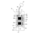
図1は本発明に係る引戸用通電装置の設けられた建具枠の正面図、図2は本発明に係る引戸用通電装置の拡大斜視図、図3はリール部の拡大斜視図、図4はリール軸線に平行な面による断面図、図5はリール軸線に垂直な面による装置筐体の断面図、図6は引戸が開方向に移動された状態の正面図、図7は筐体が引戸側に設けられた変形例の正面図である。
本発明による引戸用通電装置100は、引戸11を移動自在に保持する建物側の建具枠13と、引戸11に設けられた電気機器との間を導通させる場合に好適に用いることができる。本実施の形態では、例えば引戸11が、開口部15を開閉する片開きの引戸であり、引戸11に設けられる電気機器が電気錠17である場合を例に説明する。また、本実施の形態では、装置の主要部である筐体が建具枠13に設けられる場合を例に説明するが、後の変形例で述べるように、これとは逆に引戸11に設けられるものであってもよい。
DESCRIPTION OF EMBODIMENTS Hereinafter, preferred embodiments of a sliding door energizing apparatus according to the present invention will be described in detail with reference to the drawings.
1 is a front view of a joinery frame provided with a sliding door energizing device according to the present invention, FIG. 2 is an enlarged perspective view of the sliding door energizing device according to the present invention, FIG. 3 is an enlarged perspective view of a reel portion, and FIG. FIG. 5 is a cross-sectional view of the apparatus casing taken along a plane perpendicular to the reel axis, FIG. 6 is a front view of the apparatus when the sliding door is moved in the opening direction, and FIG. It is a front view of the modification provided in the side.
The energizing apparatus for sliding
引戸11には、建具枠13の縦枠13aに対し電気信号の入力によって施解錠を可能とする電気錠17が設けられている。なお、この電気錠17は、縦枠13aに設けられた不図示のマグネット等によってオン・オフする近接センサを備え、引戸11の開閉状態が検出できるようになっている構成としてもよい。
The sliding
引戸用通電装置100は、筐体21と、リール23と、接触子25と、ケーブル27と、付勢手段29とを主要な構成部材として有している。図2に示すように、筐体21は、リール23を収容する収容空間を有した箱状に形成され、取付板21aが縦枠13aの戸当面31にビス33により固定される。取付板21aには開口スリット35が形成され、開口スリット35はケーブル27の引き出しを可能としている。
The sliding
図3に示すように、筐体21に収容されるリール23は、一対のフランジ部23a,23aに、リール軸である軸部37が固定され、この軸部37両端が筐体21の両内壁面に回転自在に支持される。フランジ部23a,23aの外周面には、少なくとも1条ずつ、合計2条の環状導体39が設けられている。環状導体39には良好な導電性を有し、耐摩耗性に優れる銅板等の金属板が用いられる。
As shown in FIG. 3, the
図4に示すように、筐体21の上部には、導電材料からなる一対の接触子25,25が可動孔41に上下動自在に収容される。接触子25,25は、コイルばね43の付勢力により、下方向へ付勢されることで、それぞれがフランジ部外周面の環状導体39に押圧されるようになっている。
As shown in FIG. 4, a pair of
それぞれの接触子25,25にはリード線45が接続され、リード線45は筐体21の外部に導出されて先端にコネクタ47が取り付けられる。このコネクタ47は、不図示の中央制御室等から配線される信号配線に接続される。つまり、コネクタ47、リード線45、接触子25,25を介して環状導体39には信号電流が印加されるようになっている。
A
軸部37を内側に挿通するとともに、両端でフランジ部23a,23aを連結するリール筒部23bにはケーブル27が巻装される。ケーブル27は、基端がリール筒部23bに固定されるとともに、基端側導線が上記したそれぞれの環状導体39に配線49によって接続されている。本実施の形態では、ケーブル27が、複数、本実施の形態では2本の導線を平行に一体配置したフラットケーブルで構成される。これにより、リール23への巻き取り・繰り出しの際に、ケーブル27が噛み合うことなく、常に層状にスムースに巻き取ることができ、巻き取り・繰り出し動作の信頼性を高めることができるようになっている。
A
リール23に巻装されるケーブル27の先端は、引戸11に固定され、ケーブル27の先端側導線は、引戸11内に配索される引戸内配線51によって電気錠17へと接続されている。ケーブル27の先端と引戸11とは、図2に示す脱着可能なコネクタ53を介して接続されることが好ましい。これにより、コネクタ53を引戸11から脱着することで、ケーブル27は、建具枠13に設けられた筐体側に巻き取られることとなり、引戸11と筐体21との接続を容易に解除することができる。この結果、引戸11の建具枠13からの取り外しを、容易にし、メンテナンス性を向上させることができるようになっている。
The distal end of the
なお、ケーブル27の先端には、付勢手段29により張力が加わるので、例えば、図2に示すような固定具55をビス57によって引戸11に固定することで、ケーブル先端を引戸11に支持させることが好ましい。これにより、ケーブル27の張力が直接コネクタ53に作用することを防止することができる。つまり、ケーブル27の先端は、ビス57を外し、固定具55を外した後、コネクタ53を結合解除することで、引戸11から容易に取り外すことができる。
In addition, since tension is applied to the tip of the
このケーブル27の全長は、引戸11の移動距離と同等以上の長さを有する。また、ケーブル27は、断面湾曲形状にして自己真直性、例えば鋼製巻尺のような性質を付与したものであることが、弛み等が発生し難く好ましい。
The total length of the
図3,図4に示すように、一方のフランジ部23aと、筐体21の側壁との間には付勢手段29である渦巻きばね29aが配設されている。渦巻きばね29aは、ケーブル27を巻き取る回転方向へリール23を付勢する。渦巻きばね29aは、中心端部が軸部37に固定され、外周端部が筐体21に固定される。このように渦巻きばね29aが用いられることで、リール軸方向の厚みを薄厚にした付勢手段を構成することができ、その結果、筐体21をコンパクトに形成しながら、かつ十分な巻き取り力をえることができる。
As shown in FIGS. 3 and 4, a
図1に示すように、引戸11は、上縁11aが、建具枠13の上枠13bに形成される凹溝状のレール部分に配置され、このレール内にケーブル27が配置する構成としてもよく、或いは、引戸11の上縁11aが、建具枠13の上枠13bに垂設された覆板59によって覆われる構成としてもよい。この構成によれば、上枠13bの直下には、覆板59によって覆われた引戸上縁11aの略凹溝状の移動空間61が形成される。この移動空間61には、筐体21から繰り出されたケーブル27が配置されることとなる。これにより、引戸11の移動に伴い、筐体21から繰り出され、或いは巻き取られるケーブル27が、常に一定のテンションの下で、覆板59によって覆われる移動空間61内で張架されることとなり、ケーブル27が目に触れず、引戸11の周囲の見栄えを良くすることができるようになっている。
As shown in FIG. 1, the sliding
このように構成された引戸用通電装置100では、図6に示すように、引戸11が開方向に開かれると、ケーブル27が引戸11の移動に伴って筐体21から繰り出される。また、開状態の引戸11が閉方向に移動されると、渦巻きばね29aの付勢力により、ケーブル27がリール23に巻き取られて行く。したがって、引戸11が建具枠13の任意の位置に移動されても、ケーブル27が筐体21に対し、巻き取り・繰り出され、常に弛みのない一定のテンションで建具枠13と引戸11との間に張架される。これにより、建具枠13内に、筐体21を収容するのみの簡素な構造で、常時接続の引戸用通電装置100が構成可能となる。また、小型の筐体21が、建具枠13に取付けられるのみであり、建具枠13の他の部分や、引戸11に対する大きな加工が不要となる。
In the sliding
したがって、上記の引戸用通電装置100によれば、建具枠13に筐体21を設け、この筐体21にはケーブル27が繰り出し可能となるように、このケーブル27を巻装するリール23を回転自在に支持し、ケーブル27の基端側導線と導通させたリール外周の環状導体39に接触子25,25を圧接させ、この接触子25,25に信号電流を印加するとともに、先端を引戸11に固定したケーブル27の先端側導線を、引戸11の電気錠17に接続したので、引戸11が建具枠13の任意の位置に移動されても、ケーブル27が筐体21に対し、巻き取り・繰り出され、常に弛みのない一定のテンションで建具枠13と引戸11との間に張架されることとなる。
Therefore, according to the sliding
これにより、建具枠13内に、筐体21を収容するのみの簡素な構造で、常時接続のコンパクトな引戸用通電装置100を実現させることができる。また、小型の筐体21を、建具枠13に取付けするのみであり、建具枠13の他の部分や、引戸11に対する大きな加工が不要となるので、後付施工を容易にすることができる。この結果、常時監視を、簡単な後付施工により可能にすることができる。なお、この構成は、特に引戸11に筐体21の収容スペースが確保できない場合に有効となる。
Thereby, it is possible to realize a compact sliding
なお、上記の実施の形態では、建具枠13に筐体21を設け、筐体21から繰り出されるケーブル27の先端を、引戸11に固定する構成を例に説明したが、本発明に係る引戸用通電装置は、図7に示すように、上記の実施の形態とは逆に、引戸11に筐体21を設け、ケーブル27の先端を建具枠13に固定するものであってもよい。
In the above embodiment, the
すなわち、この変形例による引戸用通電装置200は、引戸11に設けられる筐体21と、筐体21に回動自在に設けられ外周面に少なくとも2条の環状導体39が設けられたリール23と、筐体21に設けられるとともにそれぞれの環状導体39に圧接され電気錠17に電気的に接続される複数の接触子25,25と、基端がリール23に固定され複数の基端側導線がそれぞれの環状導体39に接続されるとともに先端が建具枠13に固定され先端側導線に信号電流が印加されかつ引戸11の移動距離と同等以上の長さを有してリール23に巻装されるケーブル27と、筐体21とリール23との間に介装されケーブル27を巻き取る回転方向へリール23を付勢する渦巻きばね29aとを備えて構成される。
That is, the sliding
そして、ケーブル27の先端は、脱着可能なコネクタ53を介して建具枠13に接続される。
And the front-end | tip of the
この変形例による引戸用通電装置200によれば、引戸11に筐体21を設け、この筐体21にはケーブル27が繰り出し可能となるように、このケーブル27を巻装するリール23を回転自在に支持し、ケーブル27の基端側導線と導通させたリール外周の環状導体39に接触子25,25を圧接させ、この接触子25,25に電気錠17を接続するとともに、先端を建具枠13に固定したケーブル27の先端側導線に信号電流を印加したので、引戸11が建具枠13の任意の位置に移動されても、ケーブル27が筐体21に対し、巻き取り・繰り出され、常に弛みのない一定のテンションで建具枠13と引戸11との間に張架されることとなる。
According to the sliding
これにより、引戸内に、筐体21を収容するのみの簡素な構造で、常時接続のコンパクトな引戸用通電装置200を実現させることができる。また、小型の筐体21を、引戸11に取付けするのみであり、引戸11の他の部分や、建具枠13に対する大きな加工が不要となるので、後付施工を容易にすることができる。この結果、常時監視を、簡単な後付施工により可能にすることができる。なお、この構成は、特に建具枠13に筐体21の収容スペースが確保できない場合に有効となる。
Thereby, it is possible to realize a compact sliding
そして、この構成の場合においても、ケーブル27の先端が脱着可能なコネクタ53を介して建具枠13に接続されたので、コネクタ53を建具枠13から脱着することで、ケーブル27は、引戸11に設けられた筐体側に巻き取られることとなり、建具枠13と筐体21との接続を容易に解除することができる。この結果、引戸11の建具枠13からの取り外しを、容易に可能とすることができる。
And also in the case of this structure, since the front-end | tip of the
なお、上記した付勢手段29は、牽引力を発生させるものであってもよい。すなわち、ケーブル27に対する張力(テンション)を発生させるだけでなく、引戸11を牽引可能な付勢力を備える構成としてもよい。このような構成とすることで、自動的に閉鎖可能な引戸を構成できる。
The urging means 29 described above may generate traction force. That is, not only the tension | tensile_strength (tension) with respect to the
11…引戸
11a…引戸の上縁
13…建具枠
13b…建具枠の上枠
17…電気機器(電気錠)
21…筐体
23…リール
25…接触子
27…ケーブル
29…付勢手段
29a…渦巻きばね
37…リール軸(軸部)
39…環状導体
53…コネクタ
59…覆板
61…引戸上縁の移動空間
100,200…引戸用通電装置
DESCRIPTION OF
DESCRIPTION OF
DESCRIPTION OF
Claims (7)
前記建具枠に設けられる筐体と、
該筐体に回動自在に設けられ外周面に少なくとも2条の環状導体が設けられたリールと、
前記筐体に設けられるとともにそれぞれの前記環状導体に圧接され信号電流が印加される複数の接触子と、
基端が該リールに固定され複数の基端側導線がそれぞれの前記環状導体に接続されるとともに先端が前記引戸に固定され先端側導線が前記電気機器に接続されかつ前記引戸の移動距離と同等以上の長さを有して該リールに巻装されるケーブルと、
前記筐体と前記リールとの間に介装され該ケーブルを巻き取る回転方向へ前記リールを付勢する付勢手段と、
を具備したことを特徴とする引戸用通電装置。 A sliding door energization device for conducting between a building frame on the building side that holds the sliding door movably and an electrical device provided in the sliding door,
A housing provided in the joinery frame;
A reel provided rotatably on the casing and provided with at least two annular conductors on the outer peripheral surface;
A plurality of contacts provided on the casing and pressed against each of the annular conductors and applied with a signal current;
A base end is fixed to the reel, a plurality of base end side conductors are connected to the respective annular conductors, a tip end is fixed to the sliding door, and a tip end side conductor is connected to the electrical device and is equal to the moving distance of the sliding door A cable having the above length and wound around the reel;
A biasing means that is interposed between the casing and the reel and biases the reel in a rotation direction for winding the cable;
An energizing apparatus for sliding doors characterized by comprising:
前記引戸に設けられる筐体と、
該筐体に回動自在に設けられ外周面に少なくとも2条の環状導体が設けられたリールと、
前記筐体に設けられるとともにそれぞれの前記環状導体に圧接され前記電気機器に電気的に接続される複数の接触子と、
基端が該リールに固定され複数の基端側導線がそれぞれの前記環状導体に接続されるとともに先端が前記建具枠に固定され先端側導線に信号電流が印加されかつ前記引戸の移動距離と同等以上の長さを有して該リールに巻装されるケーブルと、
前記筐体と前記リールとの間に介装され該ケーブルを巻き取る回転方向へ前記リールを付勢する付勢手段と、
を具備したことを特徴とする引戸用通電装置。 A sliding door energization device for conducting between a building frame on the building side that holds the sliding door movably and an electrical device provided in the sliding door,
A housing provided in the sliding door;
A reel provided rotatably on the casing and provided with at least two annular conductors on the outer peripheral surface;
A plurality of contacts that are provided on the casing and are in pressure contact with the respective annular conductors and electrically connected to the electrical device;
A base end is fixed to the reel, a plurality of base end side conductors are connected to the respective annular conductors, a tip end is fixed to the joinery frame, a signal current is applied to the front end side conductor, and the moving distance of the sliding door is equal to A cable having the above length and wound around the reel;
A biasing means that is interposed between the casing and the reel and biases the reel in a rotation direction for winding the cable;
An energizing apparatus for sliding doors characterized by comprising:
該覆板によって覆われる引戸上縁の移動空間に、前記筐体から繰り出された前記ケーブルが配置されることを特徴とする請求項1,2,3,4のいずれか1つに記載の引戸用通電装置。 The upper edge of the sliding door is covered by a cover plate suspended from the upper frame of the joinery frame,
5. The sliding door according to claim 1, wherein the cable extended from the housing is disposed in a moving space of an upper edge of the sliding door covered by the cover plate. Energizing device.
Priority Applications (1)
| Application Number | Priority Date | Filing Date | Title |
|---|---|---|---|
| JP2006006327A JP4686366B2 (en) | 2006-01-13 | 2006-01-13 | Sliding door energizer |
Applications Claiming Priority (1)
| Application Number | Priority Date | Filing Date | Title |
|---|---|---|---|
| JP2006006327A JP4686366B2 (en) | 2006-01-13 | 2006-01-13 | Sliding door energizer |
Publications (2)
| Publication Number | Publication Date |
|---|---|
| JP2007186924A JP2007186924A (en) | 2007-07-26 |
| JP4686366B2 true JP4686366B2 (en) | 2011-05-25 |
Family
ID=38342271
Family Applications (1)
| Application Number | Title | Priority Date | Filing Date |
|---|---|---|---|
| JP2006006327A Expired - Fee Related JP4686366B2 (en) | 2006-01-13 | 2006-01-13 | Sliding door energizer |
Country Status (1)
| Country | Link |
|---|---|
| JP (1) | JP4686366B2 (en) |
Family Cites Families (3)
| Publication number | Priority date | Publication date | Assignee | Title |
|---|---|---|---|---|
| JPH076486U (en) * | 1993-06-28 | 1995-01-31 | 株式会社ゴール | Power supply device for electrical equipment in sliding doors |
| JP3121490B2 (en) * | 1994-02-28 | 2000-12-25 | 株式会社ゴール | Energizing device for sliding door |
| JPH07312484A (en) * | 1994-05-16 | 1995-11-28 | Kokusai Electric Co Ltd | Cord storage device |
-
2006
- 2006-01-13 JP JP2006006327A patent/JP4686366B2/en not_active Expired - Fee Related
Also Published As
| Publication number | Publication date |
|---|---|
| JP2007186924A (en) | 2007-07-26 |
Similar Documents
| Publication | Publication Date | Title |
|---|---|---|
| JP5389026B2 (en) | Device for assembling a linear drive | |
| JP6100015B2 (en) | Flat cable winding device and assembly method thereof | |
| CN104115356B (en) | Flat cable winding device | |
| JP2008545601A (en) | Improved reel and reel housing | |
| US9698587B2 (en) | Flat cable reeling device | |
| US10982480B2 (en) | Device for at least partially automatically actuating a door leaf | |
| US20100058669A1 (en) | Garage door power management system | |
| JP4686366B2 (en) | Sliding door energizer | |
| JP2011208369A (en) | Handrail bracket | |
| JP3558566B2 (en) | Wire harness winding method and winding device already installed | |
| US10594118B1 (en) | Cable routing system for electrified glass | |
| EP3176354A1 (en) | Actuating apparatus for sliding door | |
| JP5920825B2 (en) | Circuit breaker | |
| CN113851936B (en) | Power distribution cabinet wire leading device and power distribution cabinet | |
| JP5849217B2 (en) | Outlet | |
| CN113853467B (en) | sliding door components | |
| US4935585A (en) | Retracting electrical window and door cord | |
| KR101230457B1 (en) | Energized bracket | |
| JP2005033871A (en) | Container of flexible wire body | |
| JP2007146513A (en) | Current application device for sliding door | |
| KR101069297B1 (en) | Power supply for apartment houses with switchgear to prevent electric shock | |
| JP7705749B2 (en) | Electric opening/closing device | |
| JP3923334B2 (en) | A fixture equipped with a locking and unlocking device | |
| CN116222064B (en) | Refrigerator with take-up structure | |
| JP2015183416A (en) | electric lock system |
Legal Events
| Date | Code | Title | Description |
|---|---|---|---|
| A621 | Written request for application examination |
Free format text: JAPANESE INTERMEDIATE CODE: A621 Effective date: 20081217 |
|
| A977 | Report on retrieval |
Free format text: JAPANESE INTERMEDIATE CODE: A971007 Effective date: 20100818 |
|
| TRDD | Decision of grant or rejection written | ||
| A01 | Written decision to grant a patent or to grant a registration (utility model) |
Free format text: JAPANESE INTERMEDIATE CODE: A01 Effective date: 20110201 |
|
| A01 | Written decision to grant a patent or to grant a registration (utility model) |
Free format text: JAPANESE INTERMEDIATE CODE: A01 |
|
| A61 | First payment of annual fees (during grant procedure) |
Free format text: JAPANESE INTERMEDIATE CODE: A61 Effective date: 20110214 |
|
| FPAY | Renewal fee payment (event date is renewal date of database) |
Free format text: PAYMENT UNTIL: 20140218 Year of fee payment: 3 |
|
| R150 | Certificate of patent or registration of utility model |
Free format text: JAPANESE INTERMEDIATE CODE: R150 |
|
| LAPS | Cancellation because of no payment of annual fees |