JP4684410B2 - Light amount adjusting device, photographing lens barrel and imaging device - Google Patents
Light amount adjusting device, photographing lens barrel and imaging device Download PDFInfo
- Publication number
- JP4684410B2 JP4684410B2 JP2000382237A JP2000382237A JP4684410B2 JP 4684410 B2 JP4684410 B2 JP 4684410B2 JP 2000382237 A JP2000382237 A JP 2000382237A JP 2000382237 A JP2000382237 A JP 2000382237A JP 4684410 B2 JP4684410 B2 JP 4684410B2
- Authority
- JP
- Japan
- Prior art keywords
- filter
- optical axis
- actuator
- axis direction
- light
- Prior art date
- Legal status (The legal status is an assumption and is not a legal conclusion. Google has not performed a legal analysis and makes no representation as to the accuracy of the status listed.)
- Expired - Fee Related
Links
Images


Description
【0001】
【発明の属する技術分野】
本発明は、ビデオカメラ等の光学機器に用いられるレンズ鏡筒に関するものである。
【0002】
【従来の技術】
ビデオカメラ用のズームレンズとしては、例えば被写体側から順に固定の凸、可動の凹、固定の凸、可動の凸の4つのレンズ群から構成されるものがある。
【0003】
図9(A),(B)には、一般的な4群レンズ構成のズームレンズの鏡筒構造を示している。なお、(B)は(A)におけるA−A線断面を示している。
【0004】
このズームレンズを構成する4つのレンズ群201a〜201dは、固定された前玉レンズ201a、光軸に沿って移動することで変倍動作を行うバリエーターレンズ群201b、固定されたアフォーカルレンズ201c、および光軸に沿って移動することで変倍時の焦点面維持と焦点合わせを行うフォーカシングレンズ群201dからなる。
【0005】
ガイドバー203,204a,204bは光軸205と平行に配置され、移動するレンズ群の案内および回り止めを行う。DCモータ206はバリエーターレンズ群201bを移動させる駆動源となる。
【0006】
前玉レンズ201aは前玉鏡筒202に保持され、バリエーターレンズ群201bはV移動環211に保持されている。また、アフォーカルレンズ201cは中間枠215に、フォーカシングレンズ群201dはRR移動環214に保持されている。また、中間枠215には、絞りユニット218が保持されている。
【0007】
前玉鏡筒202は、後部鏡筒216に位置決め固定されており、両鏡筒202,216によってガイドバー203が位置決め支持されているとともに、ガイドスクリュウ軸208が回転可能に支持されている。このガイドスクリュウ軸208は、DCモータ206の出力軸206aの回転がギア列207を介して伝達されることにより回転駆動される。
【0008】
バリエーターレンズ群201bを保持するV移動環211は、押圧ばね209とこの押圧ばね209の力でガイドスクリュウ軸208に形成されたスクリュー溝208aに係合するボール210とを有しており、DCモータ206によってガイドスクリュー軸208が回転駆動されることにより、ガイドバー203にガイドおよび回転規制されながら光軸方向に進退移動する。
【0009】
後部鏡筒216とこの後部鏡筒216に位置決めされた中間枠215にはガイドバー204a,204bが嵌合支持されている。RR移動環214は、これらガイドバー204a,204bによってガイドおよび回転規制されながら光軸方向に進退可能である。
【0010】
フォーカシングレンズ群201dを保持するRR移動環214には、ガイドバー204a,204bにスライド可能に嵌合するスリーブ部が形成されており、またラック213が光軸方向についてRR移動環214と一体的となるように組み付けられている。
【0011】
ステッピングモータ212は、その出力軸に一体形成されたリードスクリュー212aを回転駆動する。リードスクリュー212aにはRR移動環214に組み付けられたラック213が係合しており、リードスクリュー212aが回転することによって、RR移動環214がガイドバー204a,204bによりガイドされながら光軸方向に移動する。
【0012】
なお、バリエーターレンズ群の駆動源としては、フォーカシングレンズ群の駆動源と同様にステッピングモータを用いてもよい。
【0013】
そして、前玉鏡筒202、中間枠215および後部鏡筒216により、レンズ等を略密閉収容するレンズ鏡筒本体が形成される。
【0014】
また、このようなステッピングモータを用いてレンズ群保持枠を移動させる場合には、フォトインタラプタ等を用いて保持枠が光軸方向の1つの基準位置に位置することを検出した後に、ステッピングモータに与える駆動パルスの数を連続的にカウントすることにより、保持枠の絶対位置を検出する。
【0015】
次に、上記絞りユニット218の構成を、図10を用いて説明する。この絞りユニット218は、2枚の絞り羽根23a,23bを、1つの回動式電磁アクチュエータ(モータ)23cによりシーソー式駆動レバー23dを介して互いに反対方向に略平行移動させるタイプの絞りユニットである。
【0016】
23eは絞りユニットの地板である。絞り羽根23aは光軸方向から見て略J字形をしており、その下側湾曲部の上縁には略半円形の大きな開口形成用切欠き23a1が形成されている。また、この開口形成用切欠き23a1の下端部23a2は逆三角形状に形成されている。
【0017】
絞り羽根23aの左側縁寄りの位置には、互いに上下方向に離間してそれぞれ上下方向に延びるガイドスリット23a3,23a4が、また、右側縁寄りの位置には上下方向に延びるガイドスリット23a5がそれぞれ形成されている。
【0018】
また、絞り羽根23aの左上側のガイドスリット24a3の上方には、左右方向に延びる連結長孔23a6が形成されている。
【0019】
そして、左側のガイドスリット23a3,23a4には、地板23eに形成された支持ピン23e1,23e2がそれぞれ係合し、右側のガイドスリット23a5には、同じく地板23eに形成された支持ピン23e3が係合している。これにより、絞り羽根23aは上下方向にのみ移動可能に地板23eに支持される。
【0020】
また、絞り羽根23bは光軸方向から見て略h字形をしており、その下側湾曲部の下縁には略半円形の大きな開口形成用切欠き23b1が形成されている。また、この開口形成用切欠き23b1の上端部23b2は三角形状に形成されている。
【0021】
絞り羽根23bの右側縁寄りの位置には、互いに上下方向に離間してそれぞれ上下方向に延びるガイドスリット23b3,23b4が、また、左側縁寄りの位置には上下方向に延びるガイドスリット23b5がそれぞれ形成されている。
【0022】
また、絞り羽根23bの右上側のガイドスリット23b3の上方には、左右方向に延びる連結長孔23b6が形成されている。
【0023】
そして、右側のガイドスリット23b3,23b4には、地板23eに形成された支持ピン23e4,23e3がそれぞれ係合し、左側のガイドスリット23b5には、支持ピン23e2が係合している。これにより、絞り羽根23bは上下方向にのみ移動可能に地板23eに支持される。
【0024】
23dはモータによって長手方向中央の位置を中心に揺動駆動されるシーソー型レバーである。そして、絞り羽根23a,23bの連結長孔23a6,23b6にはそれぞれシーソー型レバー23dの両端に設けられたピンが係合している。このため、モータが回転して駆動レバー23dが揺動すると、絞り羽根23a,23bは互いに反対方向に駆動され、それぞれの開口形成用切欠き23a1,23b1によって形成される絞り開口の開口面積が変化する。
【0025】
また、図10に示すようなタイプの絞りユニットにおいて、図11に示すように、絞り羽根23a,23bに並ぶ位置に、NDフィルタ27a〜27dを絞り開口に対して進退可能に配置したものがある(特開平2000−106649号公報等)。
【0026】
このNDフィルタ27a〜27dは、光軸方向から見て略U字形状に形成されたフィルタ保持部材26の開口部26dを覆うようにフィルタ保持部材26によって保持されている。なお、開口部26dの左右幅は絞り羽根23a,23bの各開口形成用切欠き23a1,23b1の左右幅とほぼ同じかやや大き目に形成されている。
【0027】
フィルタ保持部材26の左右縁寄りの位置には、上下方向に延びるガイドスリット26aがそれぞれ形成されており、さらに左側のガイドスリット26aの下方には、左右方向に延びる連結長孔26cが形成されている。そして、ガイドスリット26aには、本図には示していないが、図10に示す地板23eの支持ピン23e1,23e2,23e3,23e4が嵌合する。これにより、フィルタ保持部材26は上下方向にのみ移動可能に支持される。
【0028】
NDフィルタ27a〜27dは、互いに異なる透過率を有しており、最も上側に位置するNDフィルタ27aの透過率が最も高く(つまり濃度が薄く)、下側に位置するNDフィルタほど透過率が低く(濃度が濃く)なっている。
【0029】
また、24は絞りアクチュエータ(モータ)であり、その出力軸にはアーム25が取り付けられている。このアーム25の先端には駆動ピン25aが設けられており、この駆動ピン25aはフィルタ保持部材26の連結長孔26cに係合している。
【0030】
このため、絞りアクチュエータ24が作動してアーム25が揺動すると、フィルタ保持部材26が上下方向に移動し、NDフィルタ27a〜27dが絞り開口に重なる位置に対して進退する。
【0031】
なお、図示していないが、NDフィルタ(フィルタ保持部材26)の地板23eとは反対側は、このNDフィルタを地板側に押さえる押さえ板が設けられる。
【0032】
例えば明るい被写体に対して絞り口径が小さくなりすぎると、いわゆる小絞り回折による画質の劣化と焦点深度の増大によるゴミの写り込みが問題となる。特に、撮像素子が小さくなって画素ピッチが細かくなると、回折の影響も大きくなる。
【0033】
このため、上記のような絞り羽根と2種類以上のNDフィルタとを組み合わせた絞りユニットを用い、NDフィルタ27a〜27dを絞り開口(小絞り)に重ねることで、回折等を防止することが可能となる。
【0034】
【発明が解決しようとする課題】
しかしながら、上述したようにシーソー式駆動レバーを介して2枚の絞り羽根を互いに反対方向に略平行移動させるタイプの絞りユニットでは、きわめて小さな小絞り状態とした時に開口形状が異形(例えば、スリット形)になり、これに伴う回折の影響が懸念される。
【0035】
また、開口形状が異形であることは、画面の周辺光量が不均一になるという問題もある。
【0036】
また、NDフィルタを絞り羽根と別駆動する絞りユニットにおいて、絞り羽根とNDフィルタとをあまり接近して配置すると、絞り羽根がNDフィルタに引っ掛かるおそれがある。このため、特開平2000−250091号公報や特開平2000−122109号公報にて提案されているように、絞り羽根とNDフィルタとの間に両者の作動空間を仕切る仕切板を設ける必要がある。
【0037】
この場合、アクチュエータを除いた絞りユニットの光軸方向の厚みは、地板の厚みと、絞り羽根の作動空間の厚みと、仕切板の厚みと、NDフィルタの作動空間の厚みと、押さえ板の厚みとを合計したものとなり、かなり厚くなってしまうという問題もある。
【0038】
さらに、NDフィルタを絞り羽根と別駆動する絞りユニットにおいて、NDフィルタを光軸方向と略直交する平面内において上下方向に駆動すると、絞りユニット全体が上下方向に大型化するという問題がある。
【0039】
【課題を解決するための手段】
上記の課題を解決するために、本願第1の発明では、曲率を有する外縁によって光通過口を形成し、回動によって前記光通過口の開口面積を変化させる複数の遮光羽根と、前記複数の遮光羽根を駆動するための第1のアクチュエータと、前記光通過口に光軸方向において重なる位置に対し進退するNDフィルタと、前記NDフィルタを進退駆動するための第2のアクチュエータと、を有する光量調節装置であって、前記第1のアクチュエータの出力軸には、前記光軸方向に延びる第1のアームが取り付けられており、前記第1のアームは、前記第1のアクチュエータにより前記光軸直交面内において揺動駆動され、前記複数の遮光羽根に連結されており、前記第2のアクチュエータの出力軸には、前記光軸方向に延びる第2のアームが取り付けられており、前記第2のアームは、前記第2のアクチュエータにより前記光軸直交面内において揺動駆動され、前記NDフィルタに連結されており、前記光軸方向において、前記複数の遮光羽根と前記NDフィルタとの間に、前記複数の遮光羽根およびNDフィルタを支持する支持板を配置し、前記光軸方向において、前記第1のアクチュエータを前記支持板を挟んで前記遮光羽根とは反対側に配置し、前記第2のアクチュエータを前記支持板を挟んで前記NDフィルタとは反対側に配置されており、前記光軸方向において、前記第1のアームと前記第2のアームが重なる位置に配置されていることを特徴とする。
【0040】
これにより、遮光羽根を回動させるタイプの小絞り状態でも光通過口が異形となりにくい羽根機構を持つとともに、地板等の支持板自体によって遮光羽根とNDフィルタの干渉を防止して遮光羽根およびNDフィルタのスムーズな動作を確保でき、しかも第1および第2のアクチュエータを支持板を挟んで互いに反対側に配置することによって、第1および第2のアクチュエータを光軸直交方向両側に配置する場合に比べてその光軸直交方向の寸法が小さい光量調節装置を実現することが可能である。
【0041】
また、本願第2の発明では、曲率を有する外縁によって光通過口を形成する複数の遮光羽根と、光軸回りで回転する駆動リングにより前記複数の遮光羽根を回動させて前記光通過口の開口面積を変化させる羽根駆動機構と、前記駆動リングを回転駆動するための第1のアクチュエータと、前記光通過口に光軸方向において重なる位置に対し進退するNDフィルタと、前記NDフィルタを進退駆動するための第2のアクチュエータと、を有する光量調節装置であって、前記第1のアクチュエータの出力軸には、前記光軸方向に延びる第1のアームが取り付けられており、前記第1のアームは、前記第1のアクチュエータにより前記光軸直交面内において揺動駆動され、前記駆動リングに連結されており、前記第2のアクチュエータの出力軸には、前記光軸方向に延びる第2のアームが取り付けられており、前記第2のアームは、前記第2のアクチュエータにより前記光軸直交面内において揺動駆動され、前記NDフィルタに連結されており、前記光軸方向において、前記羽根駆動機構と前記NDフィルタの間に、前記羽根駆動機構および前記NDフィルタを支持する支持板を配置し、前記光軸方向において、前記第1のアクチュエータを前記支持板を挟んで前記羽根駆動機構とは反対側に配置し、前記第2のアクチュエータを前記支持板を挟んで前記NDフィルタとは反対側に配置されており、前記光軸方向において、前記第1のアームと前記第2のアームが重なる位置に配置されていることを特徴とする。
【0042】
これにより、駆動リングの回転により複数の遮光羽根を回動するタイプの小絞り状態でも光通過口が異形となりにくい羽根駆動機構を持つとともに、地板等の支持板自体によって遮光羽根とNDフィルタの干渉を防止して遮光羽根およびNDフィルタのスムーズな動作を確保でき、しかも駆動リングを支持板における光軸方向厚み内に配置することによって遮光羽根とは別駆動されるNDフィルタを備えつつも光軸方向厚みが薄く、さらには第1および第2のアクチュエータを支持板を挟んで互いに反対側に配置することによって、第1および第2のアクチュエータを光軸直交方向両側に配置する場合に比べてその光軸直交方向の寸法が小さい光量調節装置を実現することが可能である。
【0043】
なお、上記第1および第2の発明において、第1のアクチュエータを支持板を挟んで遮光羽根又は羽根駆動機構とは反対側(つまりはNDフィルタ側)に配置することにより、光軸方向において、第1のアクチュエータと絞り羽根の間に、絞り駆動レバー及び上記支持板が配置されるため、従来は支持板に対して光軸方向において、片側のみに絞り羽根、絞り駆動レバー、第1のアクチュエータがレイアウトされていたのに対して、光軸方向における省スペース化に貢献している。
【0044】
さらに、第2のアクチュエータを上記支持板を挟んでNDフィルタとは反対側(つまりは遮光羽根又は羽根駆動機構側)に配置することにより、光軸方向において、第2のアクチュエータとNDフィルタとの間に、ND駆動レバー及び上記支持板が配置されるため、従来は支持板に対して光軸方向において、片側のみにNDフィルタ、ND駆動レバー、第2のアクチュエータがレイアウトされていたのに対して、光軸方向における省スペース化に貢献している。
【0045】
また、NDフィルタとしてそれぞれ濃度が異なる複数の透過領域を有するものを用い、このNDフィルタにおける上記光通過口に重なる位置への進入方向先端側ほど濃度が薄い透過領域を配置することにより、光通過口における素通し部分(NDフィルタで覆われていない部分)とNDフィルタが重なった部分との透過率差が大きいことによる回折の影響を防ぐことが可能になる。
【0046】
また、上記の光量調節装置を含み、この光量調節装置を通して矩形の撮像素子上に像を形成する撮影レンズ鏡筒において、NDフィルタの進退駆動方向を撮像素子の辺に対して傾かせることにより、NDフィルタ駆動範囲の上記辺が延びる方向の寸法を小さくすることが可能となる。
【0047】
しかも、第2のアクチュエータによりアーム部材を揺動駆動し、このアーム部材によってNDフィルタを進退駆動する場合に、アーム部材の揺動範囲を第2のアクチュエータにおける撮像素子の上記辺を延長した方向の端部よりも光軸側に収まるようにすることで、装置全体における上記辺が延びる方向の寸法をより小さくすることが可能となる。
【0048】
このような撮影レンズ鏡筒を用いることにより、撮像装置の小型化を図ることが可能となる。
【0049】
なお、NDフィルタの進退駆動方向が上記のように斜めとなっている場合でも、NDフィルタにおける進入方向先端縁や濃度境界線を撮像素子の上辺に略平行とすることにより、NDフィルタの進退時に撮像画面中の明るさ変化に違和感が生ずるのを防止することが可能である。
【0050】
【発明の実施の形態】
図1および図2には、本発明の実施形態である光量調節ユニット(光量調節装置)を含む撮影レンズ鏡筒の構成を示している。
【0051】
これらの図において、L1は固定の第1群レンズ、L2は光軸方向に移動することにより変倍動作を行なう第2群レンズ、L3は手振れ等に応じて光軸と垂直な平面内で移動することにより像振れ補正動作を行なう第3群レンズ、L4は光軸方向に移動することにより合焦動作を行なう第4群レンズである。
【0052】
本実施形態のレンズ鏡筒において、第1群レンズL1は凸、第2群レンズL2は凹、第3群レンズL3は凸、第4群レンズL4は凸のパワーを有しており、この撮影光学系は被写体側から順に凸凹凸凸の4群構成の変倍光学系を構成する。
【0053】
1は第1群レンズL1を保持する前玉鏡筒ユニット、2は第2群レンズ群L2を保持する変倍移動枠である。また、3は第3群レンズL3を光軸と垂直な平面内で移動可能に保持するシフトユニットであり、4は第4群レンズL4を保持する合焦移動枠である。
【0054】
5はCCD等の撮像素子を固定保持する後部鏡筒であり、前玉鏡筒ユニット1と後部鏡筒5とにより2本のガイドバー6,7が位置決め固定されている。また、シフトユニット3と後部鏡筒5との間にはガイドバー8が位置決め固定されている。
【0055】
変倍移動枠2はガイドバー6,7により光軸方向に移動可能に支持され、合焦移動枠4はガイドバー6,8により光軸方向に移動可能に支持されている。なお、変倍移動枠2および合焦移動枠4はそれぞれ、一方のガイドバーに対して光軸方向に所定の長さを有するスリーブ部で嵌合することにより、光軸方向への倒れが防止され、他方のガイドバーにU溝部で係合することにより上記一方のガイドバー回りでの回転が防止される。
【0056】
シフトユニット3は前玉鏡筒ユニット1に位置決めされた上、後部鏡筒5と前玉鏡筒ユニット1との間に挟み込まれて保持されている。
【0057】
9は第1群レンズL1から光学系に入射した光量を変化させる光量調節ユニットである。
【0058】
この光量調節ユニット9は、6枚の絞り羽根を開閉揺動させて絞り口径を変化させるいわゆる虹彩絞りを有する。また、光量調節ユニット9は、3濃度のNDフィルタが絞り羽根とは別駆動で絞り開口に重なる位置に進退できるようになっている。
【0059】
光量調節ユニット9は、3本のビスにより前方からシフトユニット3に締結固定されている。この光量調節ユニット9の詳しい構成については後述する。
【0060】
後部鏡筒5は前玉鏡筒ユニット1に位置決めされ、同時に、前述のようにシフトユニット3を挟み込んだ上で3本のビスにより後方から共締め固定されている。
【0061】
10は合焦移動枠4を光軸方向に移動させるためのリードスクリューであり、その前後に軸受け形状を持つとともに後部に多極に着磁されたローターマグネット10aが固定されている。
【0062】
11はローターマグネット10aを回転させるためのステッピングモータステータユニットであり、リードスクリュー10はシフトユニット3とステッピングモータステータユニット11に設けられた軸受け部で回転可能に支持される。
【0063】
リードスクリュー10には、合焦移動枠4に取り付けられたラック4aが噛み合っており、このリードスクリュー10の回転により、ラック4aとともに合焦移動枠4が光軸方向に駆動される。
【0064】
なお、合焦移動枠4とラック4aとの間に配置されたねじりコイルバネ4bによって、合焦移動枠4がガイドバー6,8に対してガイドバー径方向に、ラック4aが合焦移動枠4に対して光軸方向に、さらにラック4aがリードスクリュー10への噛み合い方向にそれぞれ片寄せ付勢され、各部のガタをなくしている。
【0065】
12は第2群レンズL2を光軸方向に移動させるためのリードスクリューであり、その前後に軸受け形状を持つとともに後部に多極に着磁されたローターマグネット12aが固定されている。
【0066】
13はローターマグネット12aを回転させるためのステッピングモータステータユニットであり、リードスクリュー12はシフトユニット3とステッピングモータステータユニット13に設けられた軸受け部で回転可能に支持されている。
【0067】
リードスクリュー12には、変倍移動枠2に取り付けられたラック2aが噛み合っており、このリードスクリュー12の回転により、ラック2aとともに変倍移動枠2が光軸方向に駆動される。
【0068】
なお、変倍移動枠2とラック2aとの間に配置されたねじりコイルバネ2bによって、変倍移動枠2がガイドバー6,7に対してガイドバー径方向に、ラック2aが変倍移動枠2に対して光軸方向に、さらにラック2aがリードスクリュー12への噛み合い方向にそれぞれ片寄せ付勢され、各部のガタをなくしている。
【0069】
ステッピングモータステータユニット11,13はそれぞれ、後部鏡筒5に2本のビスで固定されている。
【0070】
14はフォトインタラプタからなるフォーカスリセットスイッチであり、合焦移動枠4に形成された遮光部4cの光軸方向への移動による遮光、透光の切り替わりを検出して電気信号を出力する。後述する制御回路は、このフォーカスリセットスイッチタ14からの電気信号に基づいて第4群レンズL4が基準位置に位置するか否かを判別する。このフォーカスリセットスイッチ14は1本のビスによって後部鏡筒5に固定されている。
【0071】
15はフォトインタラプタからなるズームリセットスイッチであり、変倍移動枠2に形成された遮光部2cの光軸方向への移動による遮光、透光の切り替わりを検出して電気信号を出力する。後述する制御回路は、このズームリセットスイッチ15からの電気信号に基づいて第2群レンズL2が基準位置に位置するか否かを判別する。このズームリセットスイッチ15は1本のビスによって前玉鏡筒ユニット1に固定されている。
【0072】
次に、上記シフトユニット3の構成について説明する。第3群レンズL3は、PITCH方向(カメラの縦方向)の像振れを補正するための縦方向シフトと、YAW方向(カメラの横方向)の像振れを補正するための横方向シフトとが可能である。なお、縦方向および横方向ともそれぞれ専用の駆動系およびシフト位置センサを持ち、互いに独立して駆動制御される。
【0073】
縦方向および横方向の駆動系およびシフト位置センサは光軸回りで90度位相がずれているだけで基本的に同一の構成であるので、ここでは縦方向の駆動系およびシフト位置についてのみを図2を用いて説明する。
【0074】
図2において、3bはシフトユニット3のベースとなる、レンズ鏡筒と一体化されたシフトベースである。また、3aは第3群レンズL3を保持し、シフトベース3bに対して光軸直交方向に移動可能なシフト鏡筒である。このシフト鏡筒3aには、圧縮コイルバネ3dの前端部(物体側の端部)が嵌合しており、圧縮コイルバネ3dの後端部(像面側の端部)は後述する後側のセンサーベース3cに当接している。これにより、シフト鏡筒3aは、常時シフトベース3b側(前側)に付勢される。また、シフト鏡筒3aには、後述する電磁コイル3iが位置決め固定されている。
【0075】
なお、圧縮コイルバネ3dは、その近傍に配置される検出用および駆動用磁石(これらについては後述する)に吸着してしまわないように、リン青銅線等によって形成されている。
【0076】
31は上記圧縮コイルバネ3dの付勢力によってシフトベース3bとシフト鏡筒3aとの間に挟持されたボールである。なお、図中には1つのボール31しか示していないが、実際にはボール31は光軸直交面内に略同一の周方向間隔で3つ配置されている。
【0077】
また、ボール31は、その近傍に配置される後述する駆動用磁石に吸引されないように、SUS304(オーステナイト系のステンレス鋼)等によって形成されている。
【0078】
3つのボール31が当接するシフトベース3b側の面とシフト鏡筒3a側の面とはいずれも光学系の光軸に対して垂直な面となっており、3つのボール31の呼び径を同じとすることにより、シフト鏡筒3a(つまりは第3群レンズL3)を光軸に対して直角を保ったままで保持およびシフトガイドすることができる。
【0079】
センサーベース3cは2本の位置決めピンでレンズ鏡筒に対する位置が決められ、3本のビスでシフトベース3bに結合される。
【0080】
なお、3つのボール31とそれぞれの当接面との間には、ボール31がシフトベース3bとシフト鏡筒3aとにより付勢挟持されていない状態でもボール31が当接面から容易に脱落しない程度の粘度を有する潤滑油が塗布される。これにより、圧縮コイルバネ3dの付勢力を上回る慣性力がシフト鏡筒3aに働いて、ボール31が非挟持状態になっても、ボール31の位置が容易にずれるのを防止できる。
【0081】
次に、シフト鏡筒3aの駆動機構について説明する。3jは光軸から放射方向に2極着磁された駆動用磁石、3kは駆動用磁石3jの光軸方向前側の磁束を閉じるためのヨーク、3iはシフト鏡筒3aに接着により固定されたコイル、3hは駆動用磁石3jの光軸方向後側の磁束を閉じるためのヨークである。
【0082】
ヨーク3hは、駆動用磁石3jとともにコイル3iが移動する空間を形成し、シフトベース3bに対して磁石の磁力により固定されている。これら駆動用磁石3jとヨーク3k,3hとにより磁気回路が構成されている。
【0083】
コイル3iに電流を流すと、駆動用磁石3jの2極着磁の着磁境界に対して略直角方向に、磁力線相互の反発によるローレンツ力が発生し、シフト鏡筒3aを移動させる。すなわち、シフト鏡筒3aの駆動機構は、いわゆるムービングコイル型の駆動機構を構成している。
【0084】
シフトユニット3では、このような駆動機構が縦方向および横方向に配置されているため、シフト鏡筒3aを光軸直交面内で略直交する2方向(縦方向および横方向)にシフト駆動することができる。
【0085】
シフト鏡筒3aは、圧縮コイルバネ3dによってシフトベース3bに対して3つのボール31を介して押し付けられているため、シフト鏡筒3aが駆動されるときに負荷となる摩擦力はボール31の転がり摩擦のみとなる。そして、その摩擦力は極めて小さいため、シフト鏡筒3aを微小に駆動制御することができる。
【0086】
次に、シフト鏡筒3aの位置検出について説明する。3fは光軸に対して放射方向に2極着磁された検出用磁石、3gは検出用磁石3fの光軸方向前側の磁束を閉じるためのヨークであり、両者はシフト鏡筒3aに固定されている。
【0087】
また、3eは磁束密度を電気信号に変換するホール素子であり、センサーベース3cに位置決め固定されている。これら構成要素によってシフト位置センサが構成されている。
【0088】
シフト鏡筒3aが縦もしくは横方向に駆動されると、ホール素子3eによって検出される磁束密度が変化し、この磁束密度の変化を適当な信号処理により電気信号として検出することにより、シフト鏡筒3aのシフト位置を検出することができる。
【0089】
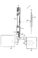
次に、上述した光量調節ユニット9の詳細な構成と動作について、図3〜図5を用いて説明する。なお、図3には、光量調節ユニット9を分解して示しており、図4には光量調節ユニット9の主要部分の断面を示している。また、図5には、光量調節ユニット9におけるNDフィルタの駆動機構を像面側から見て示している。
【0090】
9aは光量調節ユニット9において各構成要素を支持するベースとなる地板(支持板)であり、上部のリング状部分と下部のフランジ状部分とを有して構成されている。
【0091】
6枚の絞り羽根9eの外側部分には穴部9e1が形成されており、この穴部9e1には地板9aにおけるリング状部分の外周側の前面6箇所に設けられた支持ピン9a1が回動可能に嵌合している。
【0092】
また、地板9aにおけるリング状部分の内周側の前面には、外周側の前面より後方に下がったリング状の凹部9a2が形成されており、ここには駆動リング9dが光軸回りで回動可能にはめ込まれている。これにより、図4に示すように、駆動リング9dは地板9aにおけるリング状部分の光軸方向厚み内に収まっている(但し、後述する駆動ピン9d1のみ前方に突出している)。
【0093】
なお、凹部9a2の底面に相当する後端面には半球状の突起9a3が周方向複数箇所に形成されており、駆動リング9dはこの突起9a3に当接することで、凹部9a2内でスムーズに回転することができる。
【0094】
駆動リング9dの前面には駆動ピン9d1が周方向6箇所に設けられており、これら駆動ピン9d1は絞り羽根9eにおける上記穴部9e1よりも内側に形成された長穴部9e2に嵌合している。このため、駆動リング9dを光軸回りで回転させると、6枚の絞り羽根9eは地板9の支持ピン9a1を中心として開閉揺動し、これら6枚の絞り羽根9eによって形成される絞り開口の面積が変化してこの絞り開口を通過する光量が増減する。
【0095】
この際の絞り開口の形状は、開放から小絞り状態まで略円形が維持され、異形にならない。このため、小絞り状態においても周辺光量を均一にすることができる。
【0096】
なお、図4に示すように、地板9aにおけるリング状部分の前方には、6枚の絞り羽根9eと駆動リング9dを地板側に押さえるためのリング状の押さえ板9iが配置されており、地板9aに固定されている。
【0097】
また、駆動リング9dの周方向一箇所には径方向外方に延びるアーム部9d3が形成されており、このアーム部9d3の先端には長穴部9d2が形成されている。この長穴部9d2には、後述する絞り駆動アーム9cのピン部が嵌合している。
【0098】
一方、地板9の後面側には、フィルタ保持板9h1が配置されている。このフィルタ保持板9h1におけるU字形部分の前面下側には、単一の濃度(透過率32%)のNDフィルタ9h2が貼られており、またU字形部分の後面の上側から下側にかけて、透過率32%と10%の2種類の透過率エリアが上下に分かれて形成された2濃度のNDフィルタ9h3が貼られている。NDフィルタ9h3の透過率10%の領域のうち下側の部分は、NDフィルタ9h2と重なっている。
【0099】
これにより、図5に示すように、上側(絞り開口への進入方向先端側)から順に、透過率32%を有するエリア9h9と、透過率10%を有するエリア9h8と、透過率32%を有するエリア9h7の合計3種類の透過率を有した複数の濃度領域を有するNDフィルタユニット9hが構成される。
【0100】
ここで、図5に示すように、フィルタ保持板9h1は撮像素子18において上下方向に延びる短辺18a(および光軸に交わる垂直軸V)に対して斜めに傾いた形状を有する。
【0101】
そして、フィルタ保持板9h1の側端側には、同様に短辺18aに対して傾いて延びる長穴部9h12,9h13が形成されている。これら長穴部9h12,9h13には、地板9の後面に設けられたガイドピン9a4がそれぞれ嵌合している。
【0102】
また、フィルタ保持板9h1の下端には、長穴部9h12,9h13の長手方向に対して略直交する方向に延びる長穴部9h11が形成されており、この長穴部9h11には後述するND駆動アーム9gのピン部9g1が嵌合している。
【0103】
なお、図4に示すように、地板9aにおけるリング状部分の後方には、NDフィルタユニット9hを地板側に押さえるためのリング状の押さえ板9jが配置されており、地板9aに固定されている。
【0104】
さらに、地板9aにおけるフランジ状部分の後面(すなわち、地板9aを挟んで絞り羽根9eとは反対側)には、ステッピングモータからなる絞り駆動モータ(第1のアクチュエータ)9bがレイアウトされており、地板9aにおけるフランジ状部分の前面(すなわち、地板9aを挟んでNDフィルタユニット9hとは反対側)には、ステッピングモータからなるND駆動モータ(第2のアクチュエータ)9fがレイアウトされている。
【0105】
絞り駆動モータ9bの出力軸には、絞り駆動アーム9cの基端部が連結されており、この絞り駆動アーム9cの先端に設けられたピン部は、前述したように駆動リング9dの長穴部9d2に嵌合している。
【0106】
このため、絞り駆動モータ9bが回転して絞り駆動アーム9cが揺動すると、駆動リング9dが光軸回りで回転し、6枚の絞り羽根9eが開閉揺動する。
【0107】
また、ND駆動モータ9fの出力軸には、ND駆動アーム9gの基端部が連結されており、ND駆動アーム9gの先端に設けられたピン部9g1は、前述したようにフィルタ保持板9h1の長穴部9h11に嵌合している。
【0108】
このため、ND駆動モータ9fが回転してND駆動アーム9gが揺動すると、NDフィルタユニット9hは、ガイドピン9a4によって長穴部9h12,9h13がガイドされながら図5中、矢印9h14の方向に往復する。これにより、絞り羽根9eによって形成される絞り開口に対して、各NDエリア9h7〜9h9を進退させることができる。
【0109】
このとき、図5に示すように、NDフィルタユニット9hの進退方向である矢印9h14の方向は垂直軸V(短辺18a)に対して斜めに傾いており、ND駆動モータ9fは、光軸方向から見たときに、垂直軸Vに近い位置であってNDフィルタユニット9hの下側にレイアウトされている。
【0110】
このため、NDフィルタユニット9hの進退駆動を行う際に、ND駆動アーム9gの先端部(ピン部9g1)は、退避方向端において図中に9g11で示す位置に、進入方向端において9g13に示す位置に位置することになる。なお、ND駆動レバー9gの全揺動角のちょうど中央を9g12とする。
【0111】
NDフィルタユニット9hを含むフィルタ駆動機構がこのようなレイアウトをとることにより、フィルタ駆動機構として光軸直交面内において、一方向(例えば上下方向)にのみ大型化することを防ぐことができる。
【0112】
その理由は、ND駆動アーム9gのピン部9g1が全揺動角の振り分け中心9g12に位置するときに、水平軸HとND駆動アーム9gがなす角度9g2は水平軸Hに対して0゜ではなくある角度をもっており、ND駆動アーム9gのピン部9g1が光軸から最も遠い位置9g11に達したときにおいても垂直軸Vの方向でのND駆動モータ9fの最下端を通る水平線9f1よりも上側(光軸側)に収まっているからである。
【0113】
また、本実施形態のように、地板9aを挟んだ互いに反対側にモータ9b,9fを振り分けて配置することにより、例えば地板9aの一方の側の上下にモータ9b,9fを振り分けて配置するような場合に比べて、光量調節ユニット全体としての上下方向の寸法を小さくすることができる。
【0114】
また、この揺動角の振り分け中心角9g2を表す線は、NDフィルタユニット9hの進退駆動方向9h14にほぼ直交するため、ND駆動アーム9gの全揺動角をNDフィルタユニット9hの全進退ストロークに有効に使うことができる。
【0115】
このとき、NDエリア9h7の最先端部9h4および濃度境界部分9h5,9h6は水平軸Hにほぼ平行となっている。
【0116】
これは、NDエリア9h7の最先端部9h4および濃度境界部分9h5,9h6が水平軸に対して角度を持っていると、撮像素子による撮像画像が、例えばNDフィルタの進入時に画面の斜め上側の部分から斜めに暗くなり、高品位な画像が得られないからである。
【0117】
つまり、NDエリア9h7の最先端部9h4および濃度境界部分9h5,9h6が水平軸に対して平行であれば、例えばNDフィルタの進入時に撮像画面の上側から暗くなるが、実際に撮影する被写体は、画面の下側よりも上側の方が明るい場合が多い(例えば、風景撮影では画面の上側が空になり明るい)ため、ND進入時の画質に違和感はない。
【0118】
また、本実施形態では、絞り羽根9eとNDフィルタユニット9hとの間には地板9aが配置され、この地板9aによって絞り羽根9eの作動空間とNDフィルタユニット9hの作動空間とが仕切られているため、絞り羽根9eとNDフィルタユニット9hとが互いに干渉することがない。このため、絞り羽根9eとNDフィルタユニット9hのそれぞれの円滑な作動を確保することができる。
【0119】
さらに、本実施形態の光量調節ユニット9のうち駆動モータ9b,9fを除いた部分(特に、地板9aのリング状部分の前後)の光軸方向の厚みは、駆動リング9dが地板9aのリング状部分の厚み内に収まっているため、地板9aのリング状部分の厚みと、絞り羽根9eの作動空間の厚みと、NDフィルタユニット9hの作動空間の厚みと、前後の押さえ板9i,9jの厚みの合計となり、例えば地板の光軸方向外方に駆動リングを配置したり、これに加えて地板とは別に仕切板を設けたりする場合に比べて薄くすることができる。
【0120】
また、NDフィルタユニット9hは、光軸方向において地板9aを挟んでND駆動モータ9fと反対側に位置しているので、NDフィルタユニット9hとND駆動モータ9fの間に、地板9a及びND駆動レバー9gをレイアウトすることができ、従来は、光軸方向において、地板9aに対して片側のみにNDフィルタユニット9h、ND駆動レバー9g、ND駆動モータ9fがレイアウトされていたのに対して、光軸方向における省スペース化に貢献している。
【0121】
また、絞り羽根9eは光軸方向において地板9aを挟んで絞り駆動モータ9bと反対側に位置しているので、絞り羽根9eと絞り駆動モータ9bの間に、地板9a及び絞り駆動レバー9cをレイアウトすることができ、従来は、光軸方向において、地板9aに対して片側のみに絞り羽根9e、絞り駆動レバー9c、絞り駆動モータ9bがレイアウトされていたのに対して、光軸方向における省スペース化に貢献している。
【0122】
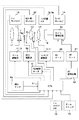
図6には、上記撮影レンズ鏡筒を備えたビデオカメラ(撮像装置)における電気的構成を示している。この図において、図1から5にて説明したレンズ鏡筒の構成要素については、これら図での符号と同符号を付して説明に代える。
【0123】
図6において、61はCPUからなる制御回路であり、ズーム駆動源としてのステッピングモータステータユニット13およびリードスクリュー12と、フォーカス駆動源としてのステッピングモータステータユニット11およびリードスクリュー10と、シフトユニット3におけるコイル3iと、絞り駆動モータ9bと、ND駆動モータ9fといった各駆動源を制御するとともに、後述する各回路等を制御する。
【0124】
また、制御回路61には、ズームおよびフォーカスリセットスイッチ15,14、カメラの振れを検出してシフトユニット3を駆動させる振れセンサ63、シフト位置センサ3e,3g、光量調節ユニット9における絞り機構およびNDフィルタユニットが初期位置に位置したことを検出するための絞り・NDリセットスイッチ62からの検出信号が入力される。
【0125】
なお、ズーム駆動源、フォーカス駆動源、絞り駆動モータ9bおよびND駆動モータ9fについては、各リセットスイッチ15,14,62により初期位置が検出された時点から各駆動源に供給される駆動パルスをカウントすることにより、位置検出を行ったり目標位置への駆動を行ったりする。
【0126】
65はカメラ信号処理回路であり、撮像素子18の出力に対して所定の増幅やガンマ補正などを施す。これらの所定の処理を受けた映像信号のコントラスト信号は、AEゲート66およびAFゲート67を通過する。すなわち、絞りやNDフィルタユニットの目標位置やシャッタ速度の決定(露出決定)およびピント合わせのために最適な信号の取り出し範囲が全画面内のうちこのゲートで設定される。このゲートの大きさは可変であったり、複数設けられたりする場合がある。
【0127】
68はAF(オートフォーカス)のためのAF信号を処理するAF信号処理回路であり、映像信号の高周波成分に関する1つもしくは複数の出力を生成する。
【0128】
70は撮影者によって操作されるズームスイッチであり、69はズームトラッキングメモリである。ズームトラッキングメモリ69は、変倍に際して被写体距離とバリエーターレンズ位置に応じてセットすべきフォーカシングレンズ位置の情報を記憶する。なお、ズームトラッキングメモリとしてCPU61内のメモリを使用してもよい。
【0129】
例えば、撮影者によりズームスイッチ70が操作されると、CPU61は、ズームトラッキングメモリ69の情報をもとに算出した第2群レンズL2と第4群レンズL4の所定の位置関係が保たれるようにズーム駆動源とフォーカス駆動源を駆動制御する。
【0130】
また、オートフォーカス動作ではAF信号処理回路68の出力がピークを示すように、CPU61は、フォーカス駆動源を駆動制御する。
【0131】
さらに、適正露出を得るために、CPU61は、AEゲート66を通過したY信号の出力の平均値を所定値として、絞り駆動モータ9bやND駆動モータ9fを駆動制御して、絞り開口径やND透過率をコントロールする。
【0132】
ここで、本実施形態における絞りが開放で、かつNDフィルタが退避した初期状態からの制御回路61による光量調節方法について説明する。
【0133】
制御回路61は、初期状態から、例えばF4.0の明るさ(暗さ)にするまでは、絞りを閉じることによってのみ光量を調節する。これは、F4.0程度までは、絞りを閉じても回折の影響による画像の劣化は起きないからである。
【0134】
そして、F4.0以上に暗くするときには、制御回路61は、NDフィルタによる光量調節を行う。
【0135】
このような制御方法を採ることによって、NDフィルタユニット9hの光束が通過する範囲をF4.0の開口径程度まで小さくすることができ、NDフィルタユニット9hひいては光量調節ユニット9の小型化を図ることができる。
【0136】
なお、絞りによる光量調節とNDフィルタによる光量調節との境界は、F4.0でなくてもよく、この値は回折の影響が起きない範囲であればより小絞り側でもよい。
【0137】
また、本実施形態では、NDフィルタユニットが3つの透過率エリア(複数の濃度領域)を有する場合について説明したが、その数は1つ又は2つの透過率エリアでも4つ以上の透過率エリアを有していてもよい。
【0138】
また、複数の透過率エリアを形成するにも、上記実施形態にて説明した方法でなくてもよく、単濃度フィルタを2枚組み合わせてもよいし、2種類以上の透過率を有したフィルタを1枚貼るだけでもよい。
【0139】
さらに、本実施形態にて説明した複数の透過率エリアの濃度は例に過ぎず、NDフィルタの進入方向先端側ほど透過率が高くなる(濃度が薄くなる)ように各透過率エリアの透過率を設定すればよい。
【0140】
(第2実施形態)
図7および図8には、本発明の第2実施形態である光量調節ユニット9の構成を示している。なお、本実施形態の基本構成は第1実施形態のものと同じであるために、共通する構成要素には同符号を付している。また、NDフィルターの開閉機構は第1実施形態と全く同じであるため、ここでは絞り羽根の開閉機構についてのみ図7および図8を用いて説明する。
【0141】
図7は光量調節ユニット9′の分解斜視図、図8はその主要断面図である。
【0142】
ここで、2枚の絞り羽根9kのそれぞれには、絞りベース9aに2箇所設けられている突起部9a2と嵌合する穴部9k1に加え、絞り駆動レバー9cと嵌合する長穴部9k2が形成されている。
【0143】
絞り駆動アクチュエータ9bの出力軸と連結された絞り駆動レバー9cが回転することによって2枚の絞り羽根9kのそれぞれが突起部9a2を回転中心として旋回し、絞り羽根9kによって形成される開口径が変化し、光量調節が行われる。
【0144】
絞り羽根9kは光軸方向において地板9aを挟んで絞り駆動モータ9bと反対側に位置している。このようにすることによって、絞り羽根9kと絞り駆動モータ9bとの間に、地板9a及び絞り駆動レバー9cをレイアウトすることができる。従来は、光軸方向において、地板9aに対して片側のみに絞り羽根9k、絞り駆動レバー9cおよび絞り駆動モータ9bがレイアウトされていたのに対して、光軸方向における省スペース化を図ることができる。
【0145】
【発明の効果】
以上説明したように、本願第1の発明によれば、遮光羽根を回動させるタイプの小絞り状態でも光通過口が異形となりにくい羽根機構を持つとともに、地板等の支持板自体によって遮光羽根とNDフィルタの干渉を防止して遮光羽根およびNDフィルタのスムーズな動作を確保でき、しかも第1および第2のアクチュエータを支持板を挟んで互いに反対側に配置することによって、第1および第2のアクチュエータを光軸直交方向両側に配置する場合に比べてその光軸直交方向の寸法が小さい光量調節装置を実現することができる。
【0146】
また、本願第2の発明によれば、駆動リングの回転により複数の遮光羽根を回動するタイプの小絞り状態でも光通過口が異形となりにくい羽根駆動機構を持つとともに、地板等の支持板自体によって遮光羽根とNDフィルタの干渉を防止して遮光羽根およびNDフィルタのスムーズな動作を確保でき、しかも駆動リングを支持板における光軸方向厚み内に配置することによって遮光羽根とは別駆動されるNDフィルタを備えつつも光軸方向厚みが薄く、さらには第1および第2のアクチュエータを支持板を挟んで互いに反対側に配置することによって、第1および第2のアクチュエータを光軸直交方向両側に配置する場合に比べてその光軸直交方向の寸法が小さい光量調節装置を実現することができる。
【0147】
なお、上記第1および第2の発明において、第1のアクチュエータを支持板を挟んで遮光羽根又は羽根駆動機構とは反対側(つまりはNDフィルタ側)に配置すれば、光軸方向において、第1のアクチュエータと絞り羽根の間に、絞り駆動レバー及び上記支持板が配置されるため、従来は支持板に対して光軸方向において、片側のみに絞り羽根、絞り駆動レバー、第1のアクチュエータがレイアウトされていたのに対して、光軸方向における省スペース化を図ることができる。
【0148】
さらに、第2のアクチュエータを上記支持板を挟んでNDフィルタとは反対側(つまりは遮光羽根又は羽根駆動機構側)に配置することにより、光軸方向において、第2のアクチュエータとNDフィルタとの間に、ND駆動レバー及び上記支持板が配置されるため、従来は支持板に対して光軸方向において、片側のみにNDフィルタ、ND駆動レバー、第2のアクチュエータがレイアウトされていたのに対して、光軸方向における省スペース化を図ることができる。
【0149】
また、NDフィルタとしてそれぞれ濃度が異なる複数の透過領域を有するものを用いる場合において、このNDフィルタにおける上記光通過口に重なる位置への進入方向先端側ほど濃度が薄い透過領域を配置すれば、光通過口における素通し部分とNDフィルタが重なった部分との透過率差が大きいことによる回折の影響を防ぐことができる。
【0150】
また、上記の光量調節装置を含み、この光量調節装置を通して矩形の撮像素子上に像を形成する撮影レンズ鏡筒において、NDフィルタの進退駆動方向を撮像素子の辺に対して傾かせるようにすれば、NDフィルタ駆動範囲の上記辺が延びる方向の寸法を小さくし、光量調節装置が光軸直交方向のいずれか一方向にのみ大型化してしまうことを防止できる。
【0151】
さらに、第2のアクチュエータによりアーム部材を揺動駆動し、このアーム部材によってNDフィルタを進退駆動する場合に、アーム部材の揺動範囲を第2のアクチュエータにおける撮像素子の上記辺を延長した方向の端部よりも光軸側に収まるようにすれば、装置全体における上記辺が延びる方向の寸法をより小さくすることができる。
【0152】
そして、このような撮影レンズ鏡筒を用いることにより、撮像装置の小型化を図ることが可能となる。
【0153】
なお、NDフィルタの進退駆動方向が上記のように斜めとなっている場合でも、NDフィルタにおける進入方向先端縁や濃度境界線を撮像素子の上辺に略平行となるようにすれば、NDフィルタの進退時に撮像画面中の明るさ変化に違和感が生ずるのを防止することができる。
【図面の簡単な説明】
【図1】本発明の第1実施形態である光量調節ユニットを備えた撮影レンズ鏡筒の分解斜視図。
【図2】上記撮影レンズ鏡筒全体の主要断面図。
【図3】上記光量調節ユニットの分解斜視図。
【図4】上記光量調節ユニットの断面図。
【図5】上記光量調節ユニットのND駆動機構を像面側から見た図。
【図6】上記撮影レンズ鏡筒を備えたビデオカメラの電気回路の構成図。
【図7】本発明の第2実施形態である光量調節ユニットの分解斜視図。
【図8】上記第2実施形態の光量調節ユニットの断面図。
【図9】従来のビデオカメラ用レンズ鏡筒の断面図。
【図10】従来の絞り装置の構成図。
【図11】従来の絞り装置の構成図。
【符号の説明】
1 前玉鏡筒ユニット
2 変倍移動枠
3 シフトユニット
4 合焦移動枠
5 後部鏡筒
6,7,8 ガイドバー
9,9′ 光量調節ユニット
9a 地板
9b 絞り駆動モータ
9d 駆動リング
9e,9k 絞り羽根
9f ND駆動モータ
9h NDフィルタユニット
10 リードスクリュー
11 ステッピングモータステータユニット
12 リードスクリュー
13 ステッピングモータステータユニット
14,15,62 リセットセンサ[0001]
BACKGROUND OF THE INVENTION
The present invention relates to a lens barrel used in an optical apparatus such as a video camera.
[0002]
[Prior art]
As a zoom lens for a video camera, for example, there is a zoom lens composed of four lens groups of a fixed convex, a movable concave, a fixed convex, and a movable convex in order from the subject side.
[0003]
9A and 9B show a lens barrel structure of a general zoom lens having a four-group lens configuration. In addition, (B) has shown the AA sectional view in (A).
[0004]
The four
[0005]
[0006]
The
[0007]
The
[0008]
The
[0009]
[0010]
The
[0011]
The stepping
[0012]
Note that a stepping motor may be used as a driving source for the variator lens group, similarly to the driving source for the focusing lens group.
[0013]
The
[0014]
Further, when moving the lens group holding frame using such a stepping motor, after detecting that the holding frame is positioned at one reference position in the optical axis direction using a photo interrupter or the like, the stepping motor The absolute position of the holding frame is detected by continuously counting the number of applied driving pulses.
[0015]
Next, the configuration of the
[0016]
23e is the base plate of the diaphragm unit so is there. The
[0017]
Guide slits 23a3 and 23a4 that are vertically spaced apart from each other and extend in the vertical direction are formed at positions near the left edge of the
[0018]
In addition, a long connecting hole 23a6 extending in the left-right direction is formed above the upper left guide slit 24a3 of the
[0019]
The left guide slits 23a3 and 23a4 are engaged with support pins 23e1 and 23e2 formed on the
[0020]
The
[0021]
Guide slits 23b3 and 23b4 that are vertically spaced apart from each other and extend in the vertical direction are formed at positions near the right edge of the
[0022]
Further, a long connecting hole 23b6 extending in the left-right direction is formed above the guide slit 23b3 on the upper right side of the
[0023]
Support pins 23e4 and 23e3 formed on the
[0024]
23d is a motor In Therefore, the seesaw type lever is driven to swing around the center in the longitudinal direction. Then, pins provided at both ends of the
[0025]
Further, in a diaphragm unit of the type as shown in FIG. 10, as shown in FIG. 11, ND filters 27a to 27d are arranged at positions aligned with the
[0026]
The ND filters 27a to 27d are held by the
[0027]
Guide slits 26 extending in the vertical direction are located near the left and right edges of the
[0028]
The ND filters 27a to 27d have different transmittances. The
[0029]
[0030]
For this reason, when the
[0031]
Although not shown, the ND filter (filter holding member) 26 On the side opposite to the
[0032]
For example, if the aperture diameter is too small for a bright subject, image quality deterioration due to so-called small aperture diffraction and dust reflection due to an increase in the depth of focus become problems. In particular, when the image sensor becomes smaller and the pixel pitch becomes finer, the influence of diffraction increases.
[0033]
For this reason, it is possible to prevent diffraction and the like by using a diaphragm unit that combines the diaphragm blades and two or more types of ND filters as described above and overlapping the ND filters 27a to 27d on the diaphragm aperture (small diaphragm). It becomes.
[0034]
[Problems to be solved by the invention]
However, as described above, in the type of diaphragm unit in which the two diaphragm blades are moved substantially in parallel to each other via the seesaw type drive lever, the opening shape is irregular (for example, a slit shape) when the diaphragm is extremely small. ), And there is concern about the effect of diffraction.
[0035]
In addition, the irregular shape of the aperture also causes a problem that the amount of light on the periphery of the screen becomes non-uniform.
[0036]
Further, in a diaphragm unit that drives the ND filter separately from the diaphragm blades, if the diaphragm blades and the ND filter are arranged too close to each other, the diaphragm blades may be caught by the ND filter. For this reason, as proposed in Japanese Patent Laid-Open Nos. 2000-250091 and 2000-122109, it is necessary to provide a partition plate for partitioning the working space between the diaphragm blades and the ND filter.
[0037]
In this case, the thickness in the optical axis direction of the aperture unit excluding the actuator is the thickness of the base plate, the operating space of the aperture blade, the thickness of the partition plate, the operating space of the ND filter, and the thickness of the holding plate. There is also a problem that it becomes the sum of and becomes quite thick.
[0038]
Further, in the diaphragm unit that drives the ND filter separately from the diaphragm blades, if the ND filter is driven in the vertical direction within a plane substantially orthogonal to the optical axis direction, there is a problem that the entire diaphragm unit is enlarged in the vertical direction.
[0039]
[Means for Solving the Problems]
In order to solve the above problem, in the first invention of the present application, A plurality of light shielding blades that form a light passage opening by an outer edge having a curvature, and change an opening area of the light passage opening by rotation, a first actuator for driving the plurality of light shielding blades, and the light passage A light amount adjusting device having an ND filter that advances and retreats with respect to a position overlapping the mouth in the optical axis direction, and a second actuator for driving the ND filter forward and backward, and an output shaft of the first actuator includes A first arm extending in the optical axis direction is attached, and the first arm is driven to swing in the plane orthogonal to the optical axis by the first actuator and connected to the plurality of light shielding blades. A second arm extending in the optical axis direction is attached to the output shaft of the second actuator, and the second arm is connected to the second actuator. The plurality of light shielding blades and the ND are driven between the plurality of light shielding blades and the ND filter in the optical axis direction. A support plate that supports the filter is disposed, and in the optical axis direction, the first actuator is disposed on the opposite side of the light shielding blade with the support plate interposed therebetween, and the second actuator is disposed with the support plate interposed therebetween. In the optical axis direction, the first arm and the second arm are arranged so as to overlap with each other. .
[0040]
As a result, the shading blade Rotate In addition to having a blade mechanism in which the light passage opening is not easily deformed even in a small aperture state of the type, the support plate itself such as the base plate can prevent interference between the light shielding blade and the ND filter, and can ensure smooth operation of the light shielding blade and the ND filter. In addition, by arranging the first and second actuators on opposite sides of the support plate, the dimensions in the direction perpendicular to the optical axis are compared with the case where the first and second actuators are arranged on both sides in the direction perpendicular to the optical axis. Can be realized.
[0041]
In the second invention of the present application, A plurality of light shielding blades that form a light passage opening by an outer edge having a curvature, and a blade driving mechanism that rotates the plurality of light shielding blades by a drive ring that rotates around the optical axis to change the opening area of the light passage opening. A first actuator for rotationally driving the drive ring, an ND filter that moves forward and backward with respect to a position overlapping the light passage port in the optical axis direction, and a second actuator for driving the ND filter forward and backward, The first arm extending in the optical axis direction is attached to the output shaft of the first actuator, and the first arm is moved by the first actuator. The second actuator is driven to swing in a plane orthogonal to the optical axis and connected to the drive ring, and the second actuator extends in the optical axis direction to the output shaft of the second actuator. An arm is attached, and the second arm is driven to swing in the plane orthogonal to the optical axis by the second actuator, and is connected to the ND filter. In the optical axis direction, the blade drive A support plate that supports the blade driving mechanism and the ND filter is disposed between the mechanism and the ND filter, and in the optical axis direction, the first actuator is sandwiched between the support plate and the blade driving mechanism. Arranged on the opposite side, the second actuator is arranged on the opposite side of the ND filter across the support plate, and the first arm and the second arm overlap in the optical axis direction. Characterized by being placed in position .
[0042]
As a result, the plurality of light shielding blades are rotated by the rotation of the drive ring. Rotation In addition to having a blade drive mechanism that makes it difficult for the light passage aperture to be deformed even in a small aperture state, the support plate such as the base plate itself prevents interference between the light shielding blade and the ND filter and ensures smooth operation of the light shielding blade and the ND filter. In addition, by disposing the drive ring within the thickness in the optical axis direction of the support plate, the ND filter driven separately from the light shielding blade is provided, but the thickness in the optical axis direction is thin, and further, the first and second actuators are provided. By arranging the support plates on opposite sides of each other, a light amount adjusting device having a smaller dimension in the direction perpendicular to the optical axis than in the case where the first and second actuators are arranged on both sides in the direction perpendicular to the optical axis is realized. Is possible.
[0043]
In the first and second aspects of the invention, the first actuator is disposed on the side opposite to the light shielding blade or the blade driving mechanism (that is, the ND filter side) with the support plate interposed therebetween, so that in the optical axis direction, Since the diaphragm drive lever and the support plate are disposed between the first actuator and the diaphragm blade, conventionally, the diaphragm blade, the diaphragm drive lever, and the first actuator are arranged only on one side in the optical axis direction with respect to the support plate. Has contributed to space saving in the optical axis direction.
[0044]
Further, by disposing the second actuator on the opposite side of the ND filter (that is, on the light shielding blade or blade driving mechanism side) with the support plate in between, the second actuator and the ND filter are arranged in the optical axis direction. Since the ND drive lever and the support plate are disposed between them, conventionally, an ND filter is provided only on one side in the optical axis direction with respect to the support plate. ND In contrast to the layout of the drive lever and the second actuator, this contributes to space saving in the optical axis direction.
[0045]
Further, by using a ND filter having a plurality of transmission regions each having a different density, and arranging a transmission region having a lighter concentration toward the front end side in the direction of entry to the position overlapping the light passage opening in the ND filter, Threaded part in mouth (Part not covered with ND filter) It is possible to prevent the influence of diffraction due to the large difference in transmittance between the portion where the ND filter and the ND filter overlap.
[0046]
Further, in the photographing lens barrel that includes the light amount adjusting device described above and forms an image on the rectangular image pickup device through the light amount adjusting device, by tilting the forward / backward driving direction of the ND filter with respect to the side of the image pickup device, It is possible to reduce the dimension in the direction in which the side of the ND filter driving range extends.
[0047]
In addition, when the arm member is driven to swing by the second actuator and the ND filter is moved forward and backward by this arm member, the swing range of the arm member is set in the direction in which the above-mentioned side of the image sensor in the second actuator is extended. By making it fit on the optical axis side with respect to the end portion, it is possible to further reduce the dimension of the entire apparatus in the direction in which the side extends.
[0048]
By using such a photographic lens barrel, it is possible to reduce the size of the imaging apparatus.
[0049]
Even when the forward / backward drive direction of the ND filter is slanted as described above, the front end edge of the ND filter and the density boundary line in the ND filter are substantially parallel to the upper side of the image sensor, so that the ND filter can be moved forward / backward. It is possible to prevent a sense of incongruity from occurring in the brightness change in the imaging screen.
[0050]
DETAILED DESCRIPTION OF THE INVENTION
1 and 2 show the configuration of a photographic lens barrel including a light amount adjustment unit (light amount adjustment device) according to an embodiment of the present invention.
[0051]
In these figures, L1 is a fixed first group lens, L2 is a second group lens that performs a zooming operation by moving in the direction of the optical axis, and L3 is moved in a plane perpendicular to the optical axis in accordance with camera shake or the like. Thus, a third lens unit L4 that performs an image blur correction operation, and a fourth lens unit L4 that performs a focusing operation by moving in the optical axis direction.
[0052]
In the lens barrel of the present embodiment, the first group lens L1 has a convex power, the second group lens L2 has a concave power, the third group lens L3 has a convex power, and the fourth group lens L4 has a convex power. The optical system constitutes a four-group variable magnification optical system having convex and concave portions in order from the subject side.
[0053]
Reference numeral 1 denotes a front lens barrel unit that holds the first lens group L1, and
[0054]
[0055]
The variable
[0056]
The shift unit 3 is positioned by the front lens barrel unit 1 and is held between the
[0057]
[0058]
The light
[0059]
The light
[0060]
The
[0061]
[0062]
[0063]
The
[0064]
Note that the
[0065]
[0066]
[0067]
The
[0068]
Note that the
[0069]
Each of the stepping
[0070]
[0071]
[0072]
Next, the configuration of the shift unit 3 will be described. The third lens unit L3 can perform a vertical shift for correcting image blur in the PITCH direction (camera vertical direction) and a horizontal shift for correcting image blur in the YAW direction (camera horizontal direction). It is. Each of the vertical direction and the horizontal direction has a dedicated drive system and a shift position sensor, and is driven and controlled independently of each other.
[0073]
Since the vertical and horizontal drive systems and shift position sensors are basically the same in configuration with only a 90 ° phase shift around the optical axis, only the vertical drive system and shift position are shown here. 2 will be described.
[0074]
In FIG. 2,
[0075]
The
[0076]
A
[0077]
Further, the
[0078]
Shift base with which three
[0079]
The
[0080]
It should be noted that the
[0081]
Next, the drive mechanism of the
[0082]
The
[0083]
When a current is passed through the
[0084]
In the shift unit 3, since such a driving mechanism is arranged in the vertical direction and the horizontal direction, the
[0085]
Since the
[0086]
Next, the position detection of the
[0087]
[0088]
When the
[0089]
Next, the detailed configuration and operation of the light
[0090]
[0091]
A hole portion 9e1 is formed in the outer portion of the six
[0092]
In addition, a ring-shaped recess 9a2 that is lowered rearward from the front surface on the outer peripheral side is formed on the front surface on the inner peripheral side of the ring-shaped portion of the
[0093]
In addition, hemispherical projections 9a3 are formed at a plurality of locations in the circumferential direction on the rear end surface corresponding to the bottom surface of the recess 9a2, and the
[0094]
Drive pins 9d1 are provided at six locations in the circumferential direction on the front surface of the
[0095]
The shape of the aperture opening at this time is maintained substantially circular from the open state to the small aperture state, and does not have an irregular shape. For this reason, the amount of peripheral light can be made uniform even in the small aperture state.
[0096]
As shown in FIG. 4, a ring-shaped pressing plate 9i for pressing the six
[0097]
Further, an arm portion 9d3 extending radially outward is formed at one circumferential direction of the
[0098]
On the other hand, a filter holding plate 9h1 is disposed on the rear surface side of the
[0099]
This As shown in FIG. Transmittance in order from the upper side (tip side in the direction of entry into the aperture) 32 % Area 9h9, 10% transmittance area 9h8, and 32% transmittance area 9h7. Has multiple concentration regions An
[0100]
Here, as shown in FIG. 5, the
[0101]
Similarly, long hole portions 9h12 and 9h13 that are inclined with respect to the
[0102]
Further, a long hole portion 9h11 extending in a direction substantially orthogonal to the longitudinal direction of the long hole portions 9h12 and 9h13 is formed at the lower end of the filter holding plate 9h1, and this long hole portion 9h11 has an ND drive described later. The pin portion 9g1 of the
[0103]
As shown in FIG. 4, a ring-shaped pressing plate 9j for pressing the
[0104]
Further, the rear surface of the flange-shaped portion of the
[0105]
The base end portion of the
[0106]
Therefore, when the
[0107]
The output shaft of the
[0108]
Therefore, when the
[0109]
At this time, as shown in FIG. 5, the direction of the arrow 9h14 which is the forward / backward direction of the
[0110]
For this reason, when the
[0111]
When the filter drive mechanism including the
[0112]
The reason for this is that when the pin portion 9g1 of the
[0113]
Further, as in the present embodiment, by arranging the
[0114]
Further, since the line representing the distribution center angle 9g2 of the swing angle is substantially orthogonal to the forward / backward drive direction 9h14 of the
[0115]
At this time, the most advanced portion 9h4 and density boundary portions 9h5 and 9h6 of the ND area 9h7 are substantially parallel to the horizontal axis H.
[0116]
This is because, when the most advanced portion 9h4 and density boundary portions 9h5 and 9h6 of the ND area 9h7 have an angle with respect to the horizontal axis, the image picked up by the image pickup device is, for example, a portion on the diagonal upper side of the screen when the ND filter enters This is because the image becomes darker and the high-quality image cannot be obtained.
[0117]
That is, if the forefront portion 9h4 and the density boundary portions 9h5 and 9h6 of the ND area 9h7 are parallel to the horizontal axis, for example, when entering the ND filter, it becomes dark from the upper side of the imaging screen. In many cases, the upper side of the screen is brighter than the lower side of the screen (for example, in landscape photography, the upper side of the screen is empty and bright).
[0118]
In the present embodiment, a
[0119]
Furthermore, the thickness of the light
[0120]
Further, since the
[0121]
Further, since the
[0122]
FIG. 6 shows an electrical configuration of a video camera (imaging device) provided with the photographing lens barrel. In this figure, the components of the lens barrel described with reference to FIGS. 1 to 5 are given the same reference numerals as those in these drawings and are not described.
[0123]
In FIG. 6,
[0124]
Further, the
[0125]
For the zoom drive source, the focus drive source, the
[0126]
A camera
[0127]
[0128]
[0129]
For example, when the photographer operates the
[0130]
In the autofocus operation, the
[0131]
Further, in order to obtain an appropriate exposure, the
[0132]
Here, a light amount adjustment method by the
[0133]
The
[0134]
And when darkening to F4.0 or more, the
[0135]
By adopting such a control method, the range through which the light beam of the
[0136]
Note that the boundary between the light amount adjustment by the diaphragm and the light amount adjustment by the ND filter does not have to be F4.0, and this value may be on the smaller diaphragm side as long as the influence of diffraction does not occur.
[0137]
In this embodiment, the ND filter unit has three transmittance areas. (Multiple concentration areas) However, the number thereof may be one or two transmittance areas or four or more transmittance areas.
[0138]
Further, the method of forming the plurality of transmittance areas may not be the method described in the above embodiment, but two single density filters may be combined, or a filter having two or more types of transmittance may be used. You can just paste one.
[0139]
Further, the density of the plurality of transmittance areas described in the present embodiment is merely an example, and the transmittance of each transmittance area is set so that the transmittance increases (the density decreases) toward the front end side of the ND filter in the approach direction. Should be set.
[0140]
(Second Embodiment)
7 and 8 show the configuration of the light
[0141]
FIG. 7 is an exploded perspective view of the light
[0142]
Here, in each of the two
[0143]
When the
[0144]
The
[0145]
【The invention's effect】
As described above, according to the first invention of the present application, the light shielding blade is Rotate In addition to having a blade mechanism in which the light passage opening is not easily deformed even in a small aperture state of the type, the support plate itself such as the base plate can prevent interference between the light shielding blade and the ND filter, and can ensure smooth operation of the light shielding blade and the ND filter. In addition, by arranging the first and second actuators on opposite sides of the support plate, the dimensions in the direction perpendicular to the optical axis are compared with the case where the first and second actuators are arranged on both sides in the direction perpendicular to the optical axis. Therefore, it is possible to realize a light amount adjusting device with a small amount.
[0146]
In addition, according to the second invention of the present application, a plurality of light shielding blades are rotated by rotation of the drive ring. Rotation In addition to having a blade drive mechanism that makes it difficult for the light passage aperture to be deformed even in a small aperture state, the support plate such as the base plate itself prevents interference between the light shielding blade and the ND filter and ensures smooth operation of the light shielding blade and the ND filter. In addition, by disposing the drive ring within the thickness in the optical axis direction of the support plate, the ND filter driven separately from the light shielding blade is provided, but the thickness in the optical axis direction is thin, and further, the first and second actuators are provided. By arranging the support plates on opposite sides of each other, a light amount adjusting device having a smaller dimension in the direction perpendicular to the optical axis than in the case where the first and second actuators are arranged on both sides in the direction perpendicular to the optical axis is realized. Can do.
[0147]
In the first and second aspects of the invention, if the first actuator is disposed on the side opposite to the light shielding blade or the blade driving mechanism (that is, the ND filter side) with the support plate interposed therebetween, Since the diaphragm drive lever and the support plate are arranged between the actuator 1 and the diaphragm blade, conventionally, the diaphragm blade, the diaphragm drive lever, and the first actuator are arranged only on one side in the optical axis direction with respect to the support plate. In contrast to the layout, space saving in the optical axis direction can be achieved.
[0148]
Further, by disposing the second actuator on the opposite side of the ND filter (that is, on the light shielding blade or blade driving mechanism side) with the support plate in between, the second actuator and the ND filter are arranged in the optical axis direction. Since the ND drive lever and the support plate are disposed between them, conventionally, an ND filter is provided only on one side in the optical axis direction with respect to the support plate. ND In contrast to the layout of the drive lever and the second actuator, space saving in the optical axis direction can be achieved.
[0149]
In addition, when using an ND filter having a plurality of transmission regions with different densities, if a transmission region with a lower concentration is arranged on the front side in the approach direction to the position overlapping the light passage port in the ND filter, It is possible to prevent the influence of diffraction due to a large difference in transmittance between the through portion at the passage opening and the portion where the ND filter overlaps.
[0150]
Further, in a photographing lens barrel that includes the light amount adjusting device and forms an image on a rectangular image pickup device through the light amount adjusting device, the forward / backward driving direction of the ND filter is inclined with respect to the side of the image pickup device. For example, the size of the ND filter driving range in the direction in which the side extends can be reduced, and the light amount adjusting device can be prevented from being enlarged only in any one direction perpendicular to the optical axis.
[0151]
Further, when the arm member is driven to swing by the second actuator, and the ND filter is moved forward and backward by this arm member, the swing range of the arm member is set in the direction in which the side of the image sensor in the second actuator is extended. If it is within the optical axis side of the end, the dimension of the entire device in the direction in which the side extends can be further reduced.
[0152]
By using such a photographing lens barrel, it is possible to reduce the size of the imaging apparatus.
[0153]
Even when the forward / backward driving direction of the ND filter is oblique as described above, if the leading edge of the ND filter and the density boundary line in the ND filter are made substantially parallel to the upper side of the image sensor, It is possible to prevent a sense of incongruity from occurring in the brightness change in the imaging screen during advance and retreat.
[Brief description of the drawings]
FIG. 1 is an exploded perspective view of a photographic lens barrel provided with a light amount adjustment unit according to a first embodiment of the present invention.
FIG. 2 is a main cross-sectional view of the entire photographing lens barrel.
FIG. 3 is an exploded perspective view of the light amount adjustment unit.
FIG. 4 is a cross-sectional view of the light quantity adjustment unit.
FIG. 5 is a diagram of an ND drive mechanism of the light quantity adjustment unit as viewed from the image plane side.
FIG. 6 is a configuration diagram of an electric circuit of a video camera provided with the photographing lens barrel.
FIG. 7 is an exploded perspective view of a light amount adjustment unit according to a second embodiment of the present invention.
FIG. 8 is a cross-sectional view of the light amount adjustment unit of the second embodiment.
FIG. 9 is a sectional view of a conventional lens barrel for a video camera.
FIG. 10 is a configuration diagram of a conventional diaphragm device.
FIG. 11 is a configuration diagram of a conventional diaphragm device.
[Explanation of symbols]
1 Front lens barrel unit
2 Scaling frame
3 Shift unit
4 Focus movement frame
5 Rear barrel
6, 7, 8 Guide bar
9,9 'Light intensity adjustment unit
9a Ground plate
9b Aperture drive motor
9d drive ring
9e, 9k aperture blade
9f ND drive motor
9h ND filter unit
10 Lead screw
11 Stepping motor stator unit
12 Lead screw
13 Stepping motor stator unit
14, 15, 62 Reset sensor
Claims (7)
前記第1のアクチュエータの出力軸には、前記光軸方向に延びる第1のアームが取り付けられており、前記第1のアームは、前記第1のアクチュエータにより前記光軸直交面内において揺動駆動され、前記複数の遮光羽根に連結されており、
前記第2のアクチュエータの出力軸には、前記光軸方向に延びる第2のアームが取り付けられており、前記第2のアームは、前記第2のアクチュエータにより前記光軸直交面内において揺動駆動され、前記NDフィルタに連結されており、
前記光軸方向において、前記複数の遮光羽根と前記NDフィルタとの間に、前記複数の遮光羽根およびNDフィルタを支持する支持板を配置し、
前記光軸方向において、前記第1のアクチュエータを前記支持板を挟んで前記遮光羽根とは反対側に配置し、前記第2のアクチュエータを前記支持板を挟んで前記NDフィルタとは反対側に配置されており、
前記光軸方向において、前記第1のアームと前記第2のアームが重なる位置に配置されていることを特徴とする光量調節装置。A plurality of light shielding blades that form a light passage opening by an outer edge having a curvature, and change an opening area of the light passage opening by rotation, a first actuator for driving the plurality of light shielding blades, and the light passage a light amount adjusting device having a ND filter for forward and backward relative to the position overlapping in the optical axis direction to the mouth, and a second actuator for advancing and retracting driving the ND filter,
A first arm extending in the optical axis direction is attached to the output shaft of the first actuator, and the first arm is driven to swing in the plane orthogonal to the optical axis by the first actuator. Is connected to the plurality of light shielding blades,
A second arm extending in the optical axis direction is attached to the output shaft of the second actuator, and the second arm is driven to swing in the plane orthogonal to the optical axis by the second actuator. And coupled to the ND filter,
In the optical axis direction, a support plate for supporting the plurality of light shielding blades and the ND filter is disposed between the plurality of light shielding blades and the ND filter,
In the optical axis direction, the first actuator is disposed on the opposite side of the light shielding blade with the support plate in between, and the second actuator is disposed on the opposite side of the ND filter with the support plate in between. Has been
The light amount adjusting device , wherein the first arm and the second arm are arranged in a position overlapping in the optical axis direction .
前記第1のアクチュエータの出力軸には、前記光軸方向に延びる第1のアームが取り付けられており、前記第1のアームは、前記第1のアクチュエータにより前記光軸直交面内において揺動駆動され、前記駆動リングに連結されており、
前記第2のアクチュエータの出力軸には、前記光軸方向に延びる第2のアームが取り付けられており、前記第2のアームは、前記第2のアクチュエータにより前記光軸直交面内において揺動駆動され、前記NDフィルタに連結されており、
前記光軸方向において、前記羽根駆動機構と前記NDフィルタの間に、前記羽根駆動機構および前記NDフィルタを支持する支持板を配置し、
前記光軸方向において、前記第1のアクチュエータを前記支持板を挟んで前記羽根駆動機構とは反対側に配置し、前記第2のアクチュエータを前記支持板を挟んで前記NDフィルタとは反対側に配置されており、
前記光軸方向において、前記第1のアームと前記第2のアームが重なる位置に配置されていることを特徴とする光量調節装置。A plurality of light shielding blades that form a light passage opening by an outer edge having a curvature, and a blade driving mechanism that rotates the plurality of light shielding blades by a drive ring that rotates around the optical axis to change the opening area of the light passage opening. a first actuator for rotating the drive ring, and the ND filter for forward and backward relative to the position overlapping in the optical axis direction to the optical passage port, a second actuator for advancing and retracting driving the ND filter, A light quantity adjusting device having
A first arm extending in the optical axis direction is attached to the output shaft of the first actuator, and the first arm is driven to swing in the plane orthogonal to the optical axis by the first actuator. Connected to the drive ring,
A second arm extending in the optical axis direction is attached to the output shaft of the second actuator, and the second arm is driven to swing in the plane orthogonal to the optical axis by the second actuator. And coupled to the ND filter,
In the optical axis direction, a support plate for supporting the blade driving mechanism and the ND filter is disposed between the blade driving mechanism and the ND filter,
In the optical axis direction, the first actuator is disposed on the opposite side of the blade drive mechanism with the support plate in between, and the second actuator is disposed on the opposite side of the ND filter with the support plate in between. Has been placed ,
The light amount adjusting device , wherein the first arm and the second arm are arranged in a position overlapping in the optical axis direction .
前記NDフィルタにおける前記光通過口に重なる位置への進入方向先端側ほど前記複数の透過領域のうち濃度が薄い透過領域が配置されていることを特徴とする請求項1又は2に記載の光量調節装置。The ND filter has a plurality of transmission regions each having a different density,
Light amount adjustment according to claim 1 or 2, characterized in that the concentration of the thin transmissive region of the plurality of transmission regions as the entering direction leading end side to the position overlapping the light passage opening is disposed in said ND filter apparatus.
前記光軸方向から見たときに、前記NDフィルタの進退駆動方向が、前記撮像素子の辺に対して傾いていることを特徴とする撮影レンズ鏡筒。A photographic lens barrel including the light amount adjusting device according to any one of claims 1 to 3 and forming an image on a rectangular imaging device through the light amount adjusting device,
When viewed from the optical axis direction, forward and backward driving direction of the ND filter, the photographing lens barrel, characterized in that is tilted with respect to the sides of the image sensor.
Priority Applications (1)
| Application Number | Priority Date | Filing Date | Title |
|---|---|---|---|
| JP2000382237A JP4684410B2 (en) | 2000-12-15 | 2000-12-15 | Light amount adjusting device, photographing lens barrel and imaging device |
Applications Claiming Priority (1)
| Application Number | Priority Date | Filing Date | Title |
|---|---|---|---|
| JP2000382237A JP4684410B2 (en) | 2000-12-15 | 2000-12-15 | Light amount adjusting device, photographing lens barrel and imaging device |
Publications (3)
| Publication Number | Publication Date |
|---|---|
| JP2002182263A JP2002182263A (en) | 2002-06-26 |
| JP2002182263A5 JP2002182263A5 (en) | 2008-02-07 |
| JP4684410B2 true JP4684410B2 (en) | 2011-05-18 |
Family
ID=18850102
Family Applications (1)
| Application Number | Title | Priority Date | Filing Date |
|---|---|---|---|
| JP2000382237A Expired - Fee Related JP4684410B2 (en) | 2000-12-15 | 2000-12-15 | Light amount adjusting device, photographing lens barrel and imaging device |
Country Status (1)
| Country | Link |
|---|---|
| JP (1) | JP4684410B2 (en) |
Families Citing this family (4)
| Publication number | Priority date | Publication date | Assignee | Title |
|---|---|---|---|---|
| JP4500487B2 (en) * | 2002-10-31 | 2010-07-14 | キヤノン株式会社 | Lens device and camera |
| JP4642405B2 (en) * | 2004-07-29 | 2011-03-02 | キヤノン株式会社 | Lens barrel and optical device |
| JP2008176062A (en) | 2007-01-18 | 2008-07-31 | Sony Corp | Light quantity adjusting device and imaging apparatus |
| EP2952959B1 (en) * | 2013-01-30 | 2020-03-11 | Canon Denshi Kabushiki Kaisha | Light quantity adjustment device and optical device |
Citations (1)
| Publication number | Priority date | Publication date | Assignee | Title |
|---|---|---|---|---|
| JP2000250091A (en) * | 1999-02-26 | 2000-09-14 | Sony Corp | Diaphragm device for photographic lens |
Family Cites Families (2)
| Publication number | Priority date | Publication date | Assignee | Title |
|---|---|---|---|---|
| JPH11142907A (en) * | 1997-11-06 | 1999-05-28 | Victor Co Of Japan Ltd | Diaphragm mechanism for lens barrel |
| JP4217325B2 (en) * | 1999-01-21 | 2009-01-28 | キヤノン株式会社 | Light control device |
-
2000
- 2000-12-15 JP JP2000382237A patent/JP4684410B2/en not_active Expired - Fee Related
Patent Citations (1)
| Publication number | Priority date | Publication date | Assignee | Title |
|---|---|---|---|---|
| JP2000250091A (en) * | 1999-02-26 | 2000-09-14 | Sony Corp | Diaphragm device for photographic lens |
Also Published As
| Publication number | Publication date |
|---|---|
| JP2002182263A (en) | 2002-06-26 |
Similar Documents
| Publication | Publication Date | Title |
|---|---|---|
| JP3950707B2 (en) | Optical equipment | |
| JP4510783B2 (en) | Optical equipment | |
| US20140212123A1 (en) | Light amount adjusting apparatus, lens barrel, and imaging apparatus | |
| JP4684386B2 (en) | Light amount adjusting device and optical apparatus | |
| JP4164330B2 (en) | Optical equipment | |
| JP4684410B2 (en) | Light amount adjusting device, photographing lens barrel and imaging device | |
| JP2007047289A (en) | Light quantity adjustment device and optical equipment | |
| JP5143177B2 (en) | Optical apparatus and light amount adjusting device | |
| JP4464184B2 (en) | Optical filter | |
| JP3704213B2 (en) | Zooming device | |
| JP4250516B2 (en) | Light amount adjusting device, optical device and photographing device | |
| JP2003035860A (en) | Optical equipment | |
| JP4950498B2 (en) | Optical equipment | |
| JP2009237409A (en) | Method of adjusting optical device | |
| JP2002006205A (en) | Automatic focusing camera | |
| JP4194314B2 (en) | Light amount adjusting device, lens device, and imaging device | |
| JP2008058392A (en) | Optical equipment | |
| JP2004045566A (en) | Lens device and imaging device equipped with the same | |
| JP4773906B2 (en) | Imaging device | |
| JP4642405B2 (en) | Lens barrel and optical device | |
| JP2010015172A (en) | Light quantity adjusting device and optical equipment | |
| JP2001222042A (en) | Filter device, lens barrel and optical equipment | |
| JP2001066486A (en) | Lens barrel and optical apparatus provided with it | |
| JP2003255214A (en) | Optical device | |
| JP2008145627A (en) | Optical device |
Legal Events
| Date | Code | Title | Description |
|---|---|---|---|
| A521 | Written amendment |
Free format text: JAPANESE INTERMEDIATE CODE: A523 Effective date: 20071217 |
|
| A621 | Written request for application examination |
Free format text: JAPANESE INTERMEDIATE CODE: A621 Effective date: 20071217 |
|
| RD03 | Notification of appointment of power of attorney |
Free format text: JAPANESE INTERMEDIATE CODE: A7423 Effective date: 20081023 |
|
| RD05 | Notification of revocation of power of attorney |
Free format text: JAPANESE INTERMEDIATE CODE: A7425 Effective date: 20081201 |
|
| A977 | Report on retrieval |
Free format text: JAPANESE INTERMEDIATE CODE: A971007 Effective date: 20101007 |
|
| A131 | Notification of reasons for refusal |
Free format text: JAPANESE INTERMEDIATE CODE: A131 Effective date: 20101019 |
|
| A521 | Written amendment |
Free format text: JAPANESE INTERMEDIATE CODE: A523 Effective date: 20101217 |
|
| TRDD | Decision of grant or rejection written | ||
| A01 | Written decision to grant a patent or to grant a registration (utility model) |
Free format text: JAPANESE INTERMEDIATE CODE: A01 Effective date: 20110208 |
|
| A01 | Written decision to grant a patent or to grant a registration (utility model) |
Free format text: JAPANESE INTERMEDIATE CODE: A01 |
|
| A61 | First payment of annual fees (during grant procedure) |
Free format text: JAPANESE INTERMEDIATE CODE: A61 Effective date: 20110209 |
|
| FPAY | Renewal fee payment (event date is renewal date of database) |
Free format text: PAYMENT UNTIL: 20140218 Year of fee payment: 3 |
|
| R150 | Certificate of patent or registration of utility model |
Free format text: JAPANESE INTERMEDIATE CODE: R150 |
|
| LAPS | Cancellation because of no payment of annual fees |