JP4683206B2 - How to remove fittings and piping - Google Patents
How to remove fittings and piping Download PDFInfo
- Publication number
- JP4683206B2 JP4683206B2 JP2005180466A JP2005180466A JP4683206B2 JP 4683206 B2 JP4683206 B2 JP 4683206B2 JP 2005180466 A JP2005180466 A JP 2005180466A JP 2005180466 A JP2005180466 A JP 2005180466A JP 4683206 B2 JP4683206 B2 JP 4683206B2
- Authority
- JP
- Japan
- Prior art keywords
- pipe
- sleeve
- joint
- holding member
- separation
- Prior art date
- Legal status (The legal status is an assumption and is not a legal conclusion. Google has not performed a legal analysis and makes no representation as to the accuracy of the status listed.)
- Expired - Fee Related
Links
Images


Landscapes
- Joints With Sleeves (AREA)
- Quick-Acting Or Multi-Walled Pipe Joints (AREA)
Description
この発明は、ホースやチューブなどの配管類の接続機構を有する管継手および配管取り外し方法に関するものである。 The present invention relates to a pipe joint having a connection mechanism for pipes such as a hose and a tube, and a pipe removing method.
従来から、油、水、エアー等の流体を流す配管のためにホースをグリッパーで保持する機構を有する管継手が使用されている(例えば、特許文献1参照)。 Conventionally, a pipe joint having a mechanism for holding a hose with a gripper has been used for piping through which fluid such as oil, water, air, etc. flows (see, for example, Patent Document 1).
図10に示すように、従来の管継手は端部に機器接続用ネジ部を有し、配管101(ホースやチューブ)の表面に継手本体102内で把持する保持部材103(グリッパー)を加圧により食い込ませ、これにより前記配管101を機器側の接続部と接続保持し、使用中の抜けを防止する構造となっている。また、使用後に配管101を抜く場合は、解除部材104(リリース)によって保持部材103の内側から機器接続用ネジ部方向に押し込むことにより、前記保持部材103を拡径して配管101への食い込みを解除させることで、容易に配管101を管継手から引き抜くことができる。つまり、必要な時にはいつでも配管101の取り外しが可能な構造となっている。
しかしながら、配管の取り外しを可能とした従来の管継手の構造でもなお、不用意な取り外し操作による流体漏れや配管抜けなどのトラブルが心配される。よって、安全性を更に考慮して、必要な時にのみ配管の取り外しが可能な構造とすることが望まれる。また、取り外し作業が不正確であった場合にも前記のトラブルが懸念されるため、取り外し作業が過去に行われたものであるか否かの作業履歴が分かるようにすることが要望されている。 However, even with the conventional pipe joint structure that allows the pipe to be removed, there are concerns about problems such as fluid leakage and pipe disconnection due to careless removal operation. Therefore, in consideration of safety, it is desirable to have a structure in which piping can be removed only when necessary. Further, since the above-mentioned trouble is concerned even when the removal work is inaccurate, it is desired to make it possible to know the work history as to whether or not the removal work has been performed in the past. .
本発明は、上記問題点を解決するためになされたもので、継手本体内にて把持される保持部材(グリッパー)で配管を保持する管継手において、ホースの取り外しを常時可能とするのではなく、必要な時にのみ配管の取り外しを可能とする管継手および配管取り外し方法を提供することを目的とする。 The present invention has been made to solve the above-described problems. In a pipe joint that holds a pipe with a holding member (gripper) held in the joint body, the hose cannot be always removed. It is an object of the present invention to provide a pipe joint and a pipe removing method that enables pipes to be removed only when necessary.
また本発明は、配管の取り外し作業を過去に行ったことの履歴を残せるようにした管継手および配管取り外し方法を提供することを目的とする。 It is another object of the present invention to provide a pipe joint and a pipe removing method that can keep a history of pipe removal work in the past.
上記目的を達成するために、本発明の管継手は、継手本体と、配管を前記継手本体内で把持する保持部材と、前記継手本体の配管挿入側の端部に装着され、前記継手本体から着脱可能であるとともに前記配管を取り外す工具の取り付けを阻止するスリーブとを有することを特徴とする。 In order to achieve the above object, a pipe joint of the present invention is attached to a joint main body, a holding member for gripping a pipe within the joint main body, and an end of the joint main body on the pipe insertion side. And a sleeve that is detachable and prevents attachment of a tool for removing the pipe.
また、本発明の管継手は、継手本体と、配管を前記継手本体内で把持する保持部材と、前記継手本体の配管挿入側の端部に装着され、分離したときに前記継手本体に残る残りスリーブと、前記継手本体から分離される分離スリーブと、前記残りスリーブと前記分離スリーブとを一体形状とする腕部とで構成されるスリーブとを有することを特徴とする。 In addition, the pipe joint of the present invention is attached to the joint main body, a holding member for gripping the pipe within the joint main body, and an end of the joint main body on the pipe insertion side, and remains remaining on the joint main body when separated. It has a sleeve constituted by a sleeve, a separation sleeve separated from the joint main body, and an arm part integrally formed with the remaining sleeve and the separation sleeve.
更に、前記腕部の少なくとも一部は前記分離時の破壊が容易なように幅が細くなっており、前記腕部の破壊の有無により前記配管の取り外し履歴が分かる構成であることを特徴とする
また、配管取り外し方法は、継手本体と、配管を前記継手本体内で把持する保持部材と、前記継手本体の配管挿入側の端部に装着され、前記継手本体から着脱可能であるとともに前記配管を取り外す工具の取り付けを阻止するスリーブとを有する管継手を用いて接続された配管を取り外す方法であって、前記スリーブを取り外す工程と、前記スリーブが取り外される前に存在した空間に配管取り外し工具を挿入して前記保持部材を前記配管の表面から引き離す工程と、前記保持部材から前記配管を引き抜く工程とを有することを特徴とする。
Further, at least a part of the arm portion is narrow so that the destruction at the time of separation is easy, and the removal history of the pipe can be known by the presence or absence of the destruction of the arm portion. The pipe removing method includes a joint body, a holding member that grips the pipe within the joint body, and a pipe insertion side end of the joint body that is attachable to and detachable from the joint body. A method of removing a pipe connected using a pipe joint having a sleeve for preventing the removal of the tool to be removed, the step of removing the sleeve, and inserting the pipe removal tool into the space that existed before the sleeve was removed And it has the process of pulling apart the said holding member from the surface of the said piping, and the process of pulling out the said piping from the said holding member, It is characterized by the above-mentioned.
更にまた、配管取り外し方法は、継手本体と、配管を前記継手本体内で把持する保持部材と、前記継手本体の配管挿入側の端部に装着され、分離したときに前記継手本体に残る残りスリーブと、前記継手本体から分離される分離スリーブと、前記残りスリーブと前記分離スリーブとを一体形状とする腕部とで構成されるスリーブとで構成された管継手を用いて接続された配管を取り外す方法であって、前記スリーブの前記分離スリーブを分離する工程と、前記分離スリーブが取り外される前に存在した空間に配管取り外し工具を挿入して前記保持部材を前記配管の表面から引き離す工程と、前記保持部材から前記配管を引き抜く工程とを有することを特徴とする。 Furthermore, the pipe removing method includes a joint main body, a holding member for gripping the pipe within the joint main body, and a remaining sleeve that is attached to the pipe insertion side end of the joint main body and remains in the joint main body when separated. A pipe connected using a pipe joint composed of a separation sleeve separated from the joint body and an arm portion integrally formed with the remaining sleeve and the separation sleeve. Separating the separation sleeve of the sleeve; inserting a pipe removal tool into a space that existed before the separation sleeve was removed; and pulling the holding member away from the surface of the pipe; And a step of pulling out the pipe from the holding member.
本発明の管継手および配管取り外し方法によれば、必要な時に管継手の配管接続口を覆うスリーブを取り外すことによって配管接続口を開放し、専用の配管取り外し工具を用いて配管の取り外しを行う構造であることから、不用意な取り外しのトラブルが防止できる。また、分離スリーブと残りスリーブとで構成したスリーブでは、分離スリーブと残りスリーブとを繋ぐ腕部の破壊により、その取り外し作業の履歴を少なくとも1回は残して知ることができ、取り外し作業が正確であったかどうかなどのトラブルの原因究明に役立てることが可能になる。 According to the pipe joint and the pipe removing method of the present invention, the pipe connecting port is opened by removing the sleeve covering the pipe connecting port of the pipe fitting when necessary, and the pipe is removed using a dedicated pipe removing tool. Therefore, troubles of inadvertent removal can be prevented. In addition, in the case of a sleeve composed of a separation sleeve and a remaining sleeve, it is possible to know the history of the removal work at least once due to the destruction of the arm connecting the separation sleeve and the remaining sleeve, and the removal work is accurate. It can be used to investigate the cause of troubles such as whether or not there was.
以下に、本発明の実施形態を図面によって説明する。 Embodiments of the present invention will be described below with reference to the drawings.
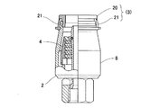
図1乃至図3は、本発明に係る管継手の実施形態を示す図である。図1は管継手に配管(ホース)1を装着していない状態の半断面図、図2は管継手に配管1を装着した状態の半断面図を示す。図3は、継手本体2の端部に装着されるスリーブ3の斜視図を示している。
1 to 3 are views showing an embodiment of a pipe joint according to the present invention. FIG. 1 is a half cross-sectional view of a pipe joint with no pipe (hose) 1 attached thereto, and FIG. 2 is a half cross-sectional view of the pipe joint with the
実施形態の管継手は、合成樹脂製の配管1を継手本体2内で把持する合成樹脂製の筒状の保持部材(グリッパー)4と、この保持部材4を所定の間隙をもって覆う外筒部(ソケット)8と、前記継手本体2の外筒部8の配管接続口側の端部に装着された合成樹脂製スリーブ3とを有する。
The pipe joint according to the embodiment includes a synthetic resin cylindrical holding member (gripper) 4 that holds the
前記保持部材4は、図1に示すように、配管接続口側の端部と奥側の端部とに、前後から交互に複数本のスリット5が長手方向に平行に形成されており、拡縮径を可能としている。また、前記保持部材4の内周面には、挿入された配管1の外周面に食い込んで強固に保持するように、複数条の環状突起帯6が配管挿入方向の向きで突設されている。
As shown in FIG. 1, the
そして、使用時に前記保持部材4と挿入された配管1が引き抜く方向に一緒に移動すると、保持部材4の環状突起帯6は、継手本体2内のテーパー面7(テーパー状の傾斜面)に沿って縮径して配管1に食い込んでいくように作用する。したがって、前記保持部材4は、配管1の外周面を全体的に押さえ込んで食い締め、しっかりと配管1を緊締する。
When the
また、継手本体2の外筒部8の配管接続口側の端部にはスリーブ3が装着されており、使用状態では外筒部8の先端の配管接続口を覆い、配管1を取り外すための専用工具が挿入できない形状となっている。これを実現する前記スリーブ3は、図2および図3に示すように、前記外筒部8の先端内周部に圧入される圧入部9と、前記外筒部8の先端外周部の溝部10と嵌合する嵌合部11とを有し、これら圧入部9と嵌合部11とが例えば二箇所の細い腕部12で繋がった一体形状となっている。
Moreover, the
前記圧入部9には、先端部の外側に向けられた突起面13が形成され、外筒部8の先端よりやや内側にある内周面側に設けられたやや浅めの溝へ、前記突起面13が圧入されている。これにより、圧入後はスリーブ3を手では容易に回転できなく、また外筒部8から抜けない圧接状態になっている。一方、前記嵌合部11は、前記外筒部8の先端よりやや内側の外周面の周囲に設けられたやや深めの溝部10へ嵌合される。溝部10には、嵌合部11によって圧接状態にはならない程度の深さが設けられているが、前記スリーブ3は溝部10にて完全に係止され抜けることはない。
The press-fitting
なお、本実施形態では前記圧入部9には突起面13を形成し、外筒部8の先端よりやや内側にある内周面側にはやや浅めの溝を設けて前記突起面13を圧入しているが、スリーブ3が前記外筒部8から抜けない圧接状態を保持できれば、必ずしも前記突起面13やそれに対応する溝は必要ない。
In the present embodiment, a
腕部12は、図1や図2にあるように180°間隔で対向する位置に二箇所配設されており、圧入部9と嵌合部11とを一体成形にて繋いでいる。この腕部12の一端は破壊され易いように、図3に示すように繋がり部14に近い方を他端(嵌合部11側)よりもより細くしており、この繋がり部14が先に破壊され易いようになっている。
As shown in FIG. 1 and FIG. 2, the
次に、この実施形態の管継手の使用状態を説明する。 Next, the use state of the pipe joint of this embodiment will be described.
実施形態の管継手に配管1が挿入された初期の段階では、合成樹脂製の保持部材4は配管1表面に軽く接触しているだけの状態である。この状態で配管1に流体が流れることによって管内部が加圧されると、内圧によって配管1と保持部材4は、図2の右側に一体的に移動し、継手本体2内壁のテーパー部7に沿って保持部材4は縮径して配管1に食い込んでいく。または、内圧をまだ加えていない状態で配管1を引き抜く方向に手で引っ張ると、配管1と保持部材4は移動して同様に継手本体2内壁のテーパー部7に沿って保持部材4は縮径して配管1に食い込んでいく。つまり、この保持部材4の縮径変形によって配管1を保持し、使用中の抜けを防止している。なお、Oリング30は流体の漏れ防止リングである。
At the initial stage when the
次に、図4乃至図7を参照して、使用後に何らかの理由で管継手から配管1を取り外す場合の方法について説明する。
Next, a method for removing the
使用状態では外筒部8の先端の配管接続口を覆っているスリーブ3の一部(図8の破壊分離スリーブ20)を破壊して取り外すことで初めて配管取り外し工具22(図7を参照)の使用が可能になる構造になっている。
In use, the pipe removal tool 22 (see FIG. 7) is not removed until a part of the sleeve 3 (
ここで図4および図5を用いて、前記スリーブ3の一部を破壊して取り外す方法について説明する。
Here, a method of breaking and removing a part of the
図4は、配管1が装着された管継手のスリーブ3の一部を破壊する専用スリーブ取り外し工具15の上面図と側面図である。まず、管継手のサイズに合った開口部16を有する専用に作成されたスリーブ取り外し工具15を、圧入部9の先端鍔部17の下端空間部18に水平に挿入する。金属製のスリーブ取り外し工具15の厚みは、前記下端空間部17へ挿入できる程度の厚みになっている。また、前記開口部16の内側の中央端部には前記スリーブ取り外し工具15を挿入時に腕部12を収納する小さな切欠部19が設けられている。したがって、切欠部19の大きさは腕部12よりやや大きいものであればよい。
FIG. 4 is a top view and a side view of a dedicated
前記スリーブ取り外し工具15が管継手にセットされた状態を、図5の上面図と側面図にて示す。この状態にてスリーブ取り外し工具15の他端を上下に手で動かして力を加えるとスリーブ3は、図5に示す腕部12の繋がり部14(最も細い部分)で二箇所とも破壊切断され、図8に示すように破壊分離スリーブ20と残りスリーブ21の二つに分離される。ここで、破壊分離スリーブ20(外筒部8の先端内周部に圧入された圧入部9に相当)は、継手本体2から離れて配管1側へ移動させる。前記残りスリーブ21は、図8に示すように継手本体2の溝部10に残る。
A state in which the
本実施形態では、腕部12を二箇所有するが、一箇所でだけでもよくさらには二箇所以上あっても同様の作用をする。
In the present embodiment, the
次に、図6および図7を用いて管継手から配管1を取り外す方法について説明する。
Next, a method for removing the
図6は、配管1に配管取り外し工具22をセットした状態を示す半断面図である。図6に示すように、別途用意した配管1のサイズに合う前記配管取り外し工具22を配管1の外周部に装着してセットする。前記配管取り外し工具22は、継手本体2への挿入側先端部22aがテーパー形状をなし保持部材4を拡径する構造となっている。なお、配管取り外し工具22を配管1の外周部に装着する機構は図示していないが、配管1の外周部からの前記配管取り外し工具22の装着作業を容易に且つ確実にするため、前記配管取り外し工具22は円筒を半分に割り一箇所が繋がった形状としている。
FIG. 6 is a half sectional view showing a state in which the
ここで、管継手から配管1を抜く時は、まず配管1を手で奥側へ押し込んでテーパー部7と保持部材4との接触を解除し、挿入初期の形状に戻す。そして、破壊分離スリーブ20が取り外される前に存在した空間23に前記配管取り外し工具22を挿入(図7の状態)して保持部材4を奥側の空間部へ押し込み、配管1の表面から保持部材4を引き離す。このことにより、前記保持部材4を拡径して配管1への食い込みを解除させることで、配管1を管継手から容易に手で引き抜くことができる。
Here, when the
配管1の取り外し後、再度配管1を取り付ける場合は、破壊分離して取り外されていた破壊分離スリーブ20を、図8および図9に示すように手で突起面13に圧入して元のように装着して再使用する。ただしこの場合、スリーブ3の腕部12は二箇所とも破壊して切断されており、この破壊の有無により取り外し作業が少なくとも1回は行われたことの履歴が一目瞭然となり認知することができる。また、残りスリーブ21は、分離したことで軽く手で回転するようになることから、このことでも取り外しの作業が実施されたことが容易に確認できる。
When the
以上の構造を持つ管継手は、使用状態では外筒部8の先端の配管接続口を覆っているスリーブ3の破壊分離スリーブ20をスリーブ取り外し工具15で破壊分離し、続いて配管取り外し工具22を用いて配管1を取り外すことで、必要な時に配管分離可能なものとすることができる。また、スリーブ3の破壊分離スリーブ20と残りスリーブ21を腕部12で結合した一体形状として形成し、腕部12に壊れやすい繋ぎ部14を設けたことで、分離の履歴を残すことができる。このことで、取り外し作業が正確であったかどうかなどのトラブルの原因究明に役立てることができる。
In the pipe joint having the above structure, in use, the
さらに、スリーブ3に配管1を取り外す解除機能(図10の解除部材104)を持たせないことで従来のものよりも継手全長が短くなり、コンパクトな管継手が得られる。さらには、配管取り外し工具22が挿入される継手本体2の外筒部8内壁と配管1外面との隙間は、解除機構が不要であることから非常に狭くすることができ、ゴミ、ホコリなどの侵入防止や配管1の根元での曲げ、繰り返し屈曲によるシール性能などの低下を抑えることが可能となる。
Further, since the
なお、配管1の取り外し作業の履歴を残すことは出来ないが、課題の一つである配管1の取り外しを常時可能とするのではなく、必要な時にのみ可能とする課題に対しては、スリーブ3を前記破壊分離スリーブ20のみとすることで解決できる。この場合、前記残りスリーブ21と腕部12は不要となる。
Although it is not possible to leave a history of the removal work of the
1 配管
2 継手本体
3 スリーブ
4 保持部材
8 外筒部
9 圧入部
11 嵌合部
12 腕部
15 スリーブ取り外し工具
20 破壊分離スリーブ
21 残りスリーブ
22 配管取り外し工具
DESCRIPTION OF
Claims (6)
配管を前記継手本体内で把持する保持部材と、
前記継手本体の配管挿入側の端部に装着され、分離したときに前記継手本体に残る残りスリーブと、前記継手本体から分離される分離スリーブと、前記残りスリーブと前記分離スリーブとを一体形状とする腕部とで構成されるスリーブと
を有することを特徴とする管継手。 The fitting body;
A holding member for gripping the pipe within the joint body;
A remaining sleeve that is attached to an end of the joint body on the pipe insertion side and that remains on the joint body when separated, a separation sleeve that is separated from the joint body, and the remaining sleeve and the separation sleeve are integrally formed. A pipe joint comprising a sleeve formed of an arm portion that performs the above-described operation.
前記継手本体の配管挿入側の端部に装着され、前記継手本体から着脱可能であるとともに前記配管を取り外す工具の取り付けを阻止するものである請求項1ないし3のいずれかに記載の管継手。 The sleeve is
The pipe joint according to any one of claims 1 to 3, wherein the pipe joint is attached to an end portion of the joint main body on a pipe insertion side and is detachable from the joint main body and prevents attachment of a tool for removing the pipe.
前記スリーブを取り外す工程と、
前記スリーブが取り外される前に存在した空間に配管取り外し工具を挿入して前記保持部材を前記配管の表面から引き離す工程と、
前記保持部材から前記配管を引き抜く工程と
を有することを特徴とする配管取り外し方法。 A method for removing a pipe connected using the pipe joint according to any one of claims 1 to 4 ,
Removing the sleeve;
Inserting a pipe removal tool into the space that existed before the sleeve was removed and pulling the holding member away from the surface of the pipe;
A method of removing the pipe from the holding member.
前記スリーブの前記分離スリーブを分離する工程と、
前記分離スリーブが取り外される前に存在した空間に配管取り外し工具を挿入して前記保持部材を前記配管の表面から引き離す工程と、
前記保持部材から前記配管を引き抜く工程と
を有することを特徴とする配管取り外し方法。 A method for removing a pipe connected using the pipe joint according to any one of claims 1 to 4 ,
Separating the separation sleeve of the sleeve;
Inserting a pipe removal tool into the space that existed before the separation sleeve was removed and pulling the holding member away from the surface of the pipe;
A method of removing the pipe from the holding member.
Priority Applications (1)
| Application Number | Priority Date | Filing Date | Title |
|---|---|---|---|
| JP2005180466A JP4683206B2 (en) | 2005-06-21 | 2005-06-21 | How to remove fittings and piping |
Applications Claiming Priority (1)
| Application Number | Priority Date | Filing Date | Title |
|---|---|---|---|
| JP2005180466A JP4683206B2 (en) | 2005-06-21 | 2005-06-21 | How to remove fittings and piping |
Publications (2)
| Publication Number | Publication Date |
|---|---|
| JP2007002866A JP2007002866A (en) | 2007-01-11 |
| JP4683206B2 true JP4683206B2 (en) | 2011-05-18 |
Family
ID=37688691
Family Applications (1)
| Application Number | Title | Priority Date | Filing Date |
|---|---|---|---|
| JP2005180466A Expired - Fee Related JP4683206B2 (en) | 2005-06-21 | 2005-06-21 | How to remove fittings and piping |
Country Status (1)
| Country | Link |
|---|---|
| JP (1) | JP4683206B2 (en) |
Cited By (1)
| Publication number | Priority date | Publication date | Assignee | Title |
|---|---|---|---|---|
| CN103908743A (en) * | 2012-12-29 | 2014-07-09 | 北京谊安医疗系统股份有限公司 | Clamping pipe joint |
Families Citing this family (2)
| Publication number | Priority date | Publication date | Assignee | Title |
|---|---|---|---|---|
| JP5805981B2 (en) * | 2011-04-14 | 2015-11-10 | 株式会社ブリヂストン | Joint structure, header base and header |
| JP6167084B2 (en) | 2014-09-12 | 2017-07-19 | 株式会社ニフコ | Connection structure for connecting pipe members to the connection object |
Citations (2)
| Publication number | Priority date | Publication date | Assignee | Title |
|---|---|---|---|---|
| JP2000508416A (en) * | 1997-12-11 | 2000-07-04 | レグリ ソシエテ アノニム | Quick connection device for connecting the tube to the rigid element, having a ring against extraction and a safety seal |
| JP2003056765A (en) * | 2001-08-14 | 2003-02-26 | Comap | Method of releasing connection of conduit end from outside of joint, and connecting device corresponding to it |
-
2005
- 2005-06-21 JP JP2005180466A patent/JP4683206B2/en not_active Expired - Fee Related
Patent Citations (2)
| Publication number | Priority date | Publication date | Assignee | Title |
|---|---|---|---|---|
| JP2000508416A (en) * | 1997-12-11 | 2000-07-04 | レグリ ソシエテ アノニム | Quick connection device for connecting the tube to the rigid element, having a ring against extraction and a safety seal |
| JP2003056765A (en) * | 2001-08-14 | 2003-02-26 | Comap | Method of releasing connection of conduit end from outside of joint, and connecting device corresponding to it |
Cited By (2)
| Publication number | Priority date | Publication date | Assignee | Title |
|---|---|---|---|---|
| CN103908743A (en) * | 2012-12-29 | 2014-07-09 | 北京谊安医疗系统股份有限公司 | Clamping pipe joint |
| CN103908743B (en) * | 2012-12-29 | 2016-03-02 | 北京谊安医疗系统股份有限公司 | Pinch points |
Also Published As
| Publication number | Publication date |
|---|---|
| JP2007002866A (en) | 2007-01-11 |
Similar Documents
| Publication | Publication Date | Title |
|---|---|---|
| JP2011106596A (en) | Pipe joint | |
| JP4058409B2 (en) | Support sleeve for use in a pipe joint and joint housing for use with said sleeve | |
| JP2008069811A (en) | Bite-into type pipe joint, refrigeration device and water heater | |
| JP4679240B2 (en) | Pipe fitting | |
| JP4705073B2 (en) | PTC mating cartridge | |
| JP4683206B2 (en) | How to remove fittings and piping | |
| JP5581079B2 (en) | Pipe fitting | |
| JP4358425B2 (en) | Pipe fitting | |
| JP2006242348A (en) | Pipe joint | |
| JP2008111531A (en) | Pipe fitting lock ring and pipe fitting | |
| JP2001200972A (en) | Tube joint | |
| WO2021100291A1 (en) | Pipe joint | |
| JP2009270622A (en) | Pipe joint | |
| JP2006316877A (en) | Pipe fitting structure | |
| JP4547137B2 (en) | Plug-in fittings | |
| JP5489666B2 (en) | Pipe fitting | |
| JP2003227592A (en) | Pipe joint | |
| JP3427766B2 (en) | Pipe fittings | |
| JP2009092153A (en) | Lock ring for pipe fitting and pipe fitting | |
| JP2009287646A (en) | Pipe joint | |
| JP5507902B2 (en) | Pipe joint mechanism, pipe joint, pipe connection method using pipe joint, pipe connection and separation method using pipe joint, and piping structure | |
| JP4865419B2 (en) | Pipe fitting device | |
| JP3059366B2 (en) | Pipe connection structure and pipe fittings | |
| JP2006009997A (en) | Tube fitting | |
| JP4783745B2 (en) | Pipe fitting |
Legal Events
| Date | Code | Title | Description |
|---|---|---|---|
| A621 | Written request for application examination |
Free format text: JAPANESE INTERMEDIATE CODE: A621 Effective date: 20080617 |
|
| A977 | Report on retrieval |
Free format text: JAPANESE INTERMEDIATE CODE: A971007 Effective date: 20100715 |
|
| A131 | Notification of reasons for refusal |
Free format text: JAPANESE INTERMEDIATE CODE: A131 Effective date: 20100726 |
|
| A521 | Written amendment |
Free format text: JAPANESE INTERMEDIATE CODE: A523 Effective date: 20100924 |
|
| A711 | Notification of change in applicant |
Free format text: JAPANESE INTERMEDIATE CODE: A712 Effective date: 20101012 |
|
| RD04 | Notification of resignation of power of attorney |
Free format text: JAPANESE INTERMEDIATE CODE: A7424 Effective date: 20101118 |
|
| TRDD | Decision of grant or rejection written | ||
| A01 | Written decision to grant a patent or to grant a registration (utility model) |
Free format text: JAPANESE INTERMEDIATE CODE: A01 Effective date: 20110106 |
|
| A01 | Written decision to grant a patent or to grant a registration (utility model) |
Free format text: JAPANESE INTERMEDIATE CODE: A01 |
|
| A61 | First payment of annual fees (during grant procedure) |
Free format text: JAPANESE INTERMEDIATE CODE: A61 Effective date: 20110125 |
|
| FPAY | Renewal fee payment (event date is renewal date of database) |
Free format text: PAYMENT UNTIL: 20140218 Year of fee payment: 3 |
|
| R150 | Certificate of patent or registration of utility model |
Free format text: JAPANESE INTERMEDIATE CODE: R150 |
|
| LAPS | Cancellation because of no payment of annual fees |