JP4681868B2 - Information processing apparatus and control method therefor, computer program, and storage medium - Google Patents
Information processing apparatus and control method therefor, computer program, and storage medium Download PDFInfo
- Publication number
- JP4681868B2 JP4681868B2 JP2004364783A JP2004364783A JP4681868B2 JP 4681868 B2 JP4681868 B2 JP 4681868B2 JP 2004364783 A JP2004364783 A JP 2004364783A JP 2004364783 A JP2004364783 A JP 2004364783A JP 4681868 B2 JP4681868 B2 JP 4681868B2
- Authority
- JP
- Japan
- Prior art keywords
- module
- area
- processing apparatus
- information processing
- determined
- Prior art date
- Legal status (The legal status is an assumption and is not a legal conclusion. Google has not performed a legal analysis and makes no representation as to the accuracy of the status listed.)
- Expired - Fee Related
Links
- 238000000034 method Methods 0.000 title claims description 85
- 230000010365 information processing Effects 0.000 title claims description 38
- 238000004590 computer program Methods 0.000 title claims description 4
- 230000006870 function Effects 0.000 claims description 79
- 230000008569 process Effects 0.000 claims description 21
- 230000001404 mediated effect Effects 0.000 claims description 3
- 238000010586 diagram Methods 0.000 description 9
- 230000008676 import Effects 0.000 description 7
- 239000008186 active pharmaceutical agent Substances 0.000 description 4
- 239000000700 radioactive tracer Substances 0.000 description 4
- 238000013500 data storage Methods 0.000 description 3
- 230000002093 peripheral effect Effects 0.000 description 2
- 239000000126 substance Substances 0.000 description 2
- 230000005856 abnormality Effects 0.000 description 1
- 230000008859 change Effects 0.000 description 1
- 230000000295 complement effect Effects 0.000 description 1
- 230000004048 modification Effects 0.000 description 1
- 238000012986 modification Methods 0.000 description 1
Images


Classifications
-
- G—PHYSICS
- G06—COMPUTING; CALCULATING OR COUNTING
- G06F—ELECTRIC DIGITAL DATA PROCESSING
- G06F11/00—Error detection; Error correction; Monitoring
- G06F11/36—Preventing errors by testing or debugging software
- G06F11/362—Software debugging
- G06F11/3636—Software debugging by tracing the execution of the program
Description
本発明は、情報処理装置及びその制御方法、コンピュータプログラム及び記憶媒体に関する。 The present invention relates to an information processing apparatus, a control method thereof, a computer program, and a storage medium.
再現率の低いソフトウェアの障害に対しては、ソフトウェアの処理ログを取得することによって対処している場合が多いが、従来、処理ログの取得はアプリケーションソフトウェアのモジュール自体に手を加えて、処理ログ取得ルーチンを追加することによって行なわれている。しかし、ログ取得コードを埋め込む等のアプリケーションソフトウェアの修正を必要とする上記の方式では、修正処理が煩雑化する。 Software failures with low recall are often dealt with by acquiring software processing logs. Conventionally, acquisition of processing logs has been done by modifying the application software module itself. This is done by adding an acquisition routine. However, in the above-described method that requires correction of application software such as embedding a log acquisition code, the correction process becomes complicated.
そこで、複数にモジュール分けされているソフトウェアにおいて、アプリケーションソフトウェアに相当するモジュールから別のモジュール内に存在する関数への呼び出しを仲介し、当該呼び出しに応じた別モジュールにおける処理のログを取得するログ取得用モジュールを提供することにより、アプリケーションソフトウェア自体の煩雑な修正を行わずとも、処理ログを取得可能とする方法が提案されている。 Therefore, in software divided into multiple modules, log acquisition that mediates a call from a module corresponding to application software to a function existing in another module, and acquires a processing log in another module according to the call A method has been proposed in which a processing log can be acquired without providing a complicated modification of application software itself by providing an application module.
このようなログ取得用モジュールによりログをバイナリデータとして取得する場合、関数のパラメータに定義されているメモリポインタに基づいてデータへアクセスし保存することとなる。この時、アプリケーションソフトウェアの障害等により、バイナリデータの一部もしくは全てがアクセス禁止となる不正な領域に置かれてしまった場合、ログ取得ソフトウェアがその領域にアクセスすることで例外が発生してしまうので、対応する例外処理を行なわなければならない(特許文献1参照)。
これに対して、また、アプリケーションソフトウェア自体を変更しメモリの不正アクセスを検知する方法は提案されているが、アプリケーションソフトウェア自体の変更が煩雑であるため効果的ではない。 On the other hand, a method for detecting unauthorized access to the memory by changing the application software itself has been proposed, but it is not effective because the change of the application software itself is complicated.
そこで、本発明では、アプリケーションソフトウェア自体の変更を行わずに、ログの不正領域への書き込み防止を可能とすることを目的とする。 Therefore, an object of the present invention is to make it possible to prevent a log from being written to an unauthorized area without changing the application software itself.
上記課題を解決するために、第1のモジュールと、第2のモジュールと、前記第1のモジュールから前記第2のモジュール内の関数への呼び出しを仲介し、前記呼び出しに応じた前記第2のモジュールにおける処理のログを取得するための第3のモジュールと、を実行する情報処理装置であって、
前記第3のモジュールが、
前記ログを取得するログ取得手段と、
取得された前記ログから、前記第2のモジュール内の関数の引数として含まれている、バイナリデータの格納されている領域の先頭を表す書込開始アドレスと、データサイズとの情報を取得する情報取得手段と、
前記書込開始アドレスと前記データサイズとから、前記バイナリデータの書き込まれている領域を決定する領域決定手段と、
決定された前記領域へのアクセスが許可されているか否かをOSに問い合わせる問い合わせ手段と、
前記問い合わせの結果により前記決定された領域のうち一部の領域のみのアクセスが許可されている場合に、前記一部の領域に対応する前記バイナリデータの一部をメモリへ書込を行う書込制御手段と
を備える。
In order to solve the above-mentioned problem, a call from a first module, a second module, and a function in the second module from the first module is mediated, and the second module according to the call A third module for obtaining a processing log in the module;
The third module is
Log acquisition means for acquiring the log;
Information for acquiring information on the write start address and the data size, which is included as an argument of the function in the second module and indicates the head of the area where binary data is stored , from the acquired log Acquisition means;
From said data size and the write start address, and area determination means for determining Tei Ru region written with the binary data,
Or allowed determined access to the area Tei Luca whether the inquiry means for inquiring the OS,
If access only a portion of the area of said is the determined by the results of the query area is allowed, writing to a portion of the binary data corresponding to the partial region performs writing to memory Control means.
本発明によれば、アプリケーションソフトウェア自体の変更を行わずに、ログの不正領域への書き込みを防止することができる。 According to the present invention, it is possible to prevent a log from being written to an unauthorized area without changing the application software itself.
以下、添付する図面を参照して本発明の実施形態を説明する。 Hereinafter, embodiments of the present invention will be described with reference to the accompanying drawings.
図1は、本実施形態に対応する情報処理装置の構成の一例を示す図である。説明を簡略化するために、本実施形態では、情報処理システムが1台のPC内部に構築されるものとするが、本発明の特徴は1台のPC内部に構築されるか、あるいは複数のPCにネットワークシステムとして構築されるかによらず有効である。 FIG. 1 is a diagram illustrating an example of a configuration of an information processing apparatus corresponding to the present embodiment. In order to simplify the description, in this embodiment, the information processing system is built inside a single PC. However, the feature of the present invention is built inside a single PC or a plurality of information processing systems. It is effective regardless of whether it is constructed as a network system on a PC.
本情報処理装置には、CPU1、チップセット2、RAM3、ハードディスクコントローラ4、ディスプレイコントローラ5、ハードディスクドライブ6、CD-ROMドライブ7、ディスプレイ8が搭載されている。また、CPU1とチップセット2とを繋ぐ信号線11、チップセット2とRAM3とを繋ぐ信号線12、チップセット2と各種周辺機器4、5とを繋ぐ周辺機器バス13、ハードディスクコントローラ4とハードディスクドライブ6とを繋ぐ信号線14、ハードディスクコントローラ4とCD-ROMドライブ7とを繋ぐ信号線15、ディスプレイコントローラ5とディスプレイ8とを繋ぐ信号線16が搭載されている。
The information processing apparatus includes a
本実施形態に対応する情報処理装置を説明するために、まず図2を参照して、複数のモジュールに分かれたソフトウェアが、通常の状態でどのようにメモリにロードされるかを説明する。図2は、RAMの内部構成の一例を示す図である。 In order to describe the information processing apparatus corresponding to the present embodiment, first, with reference to FIG. 2, how the software divided into a plurality of modules is loaded into the memory in a normal state will be described. FIG. 2 is a diagram illustrating an example of the internal configuration of the RAM.
通常、複数のモジュールに分割されたソフトウェアは、全体の制御を行なう実行ファイルEXE(23)と、モジュールとして存在しEXEの補完的な役割を担うダイナミックリンクライブラリDLL(27)とに分かれて存在する。そして、RAM3にはEXEとDLLの両方がロードされる。EXEはコードセグメント(28)とデータセグメント(29)、及び、インポート関数アドレステーブル(22)で構成される。このうち、インポート関数アドレステーブルは、関数の所属するDLLによって更に分割されており(21及び24)、DLLごとにそれぞれの関数がロードされたアドレスが書かれている(30〜35)。 Usually, the software divided into a plurality of modules is divided into an executable file EXE (23) that performs overall control and a dynamic link library DLL (27) that exists as a module and plays a complementary role of the EXE. . RAM 3 is loaded with both EXE and DLL. The EXE includes a code segment (28), a data segment (29), and an import function address table (22). Of these, the import function address table is further divided by the DLL to which the function belongs (21 and 24), and the address at which each function is loaded is written for each DLL (30 to 35).
DLLの関数の実体は、DLLごとに分けて(25,26)ロードされ、それぞれの関数は該当するDLLの一部としてロードされる(36〜41)。この図では、1本のEXEがA.DLL及びB.DLLの2つのダイナミックリンクライブラリ内の関数を使用している例を示しており、実際に使用される関数はFunc AA, Func AB, Func AC, Func BA, Func BB, Func BCの6個となっている。 The substance of the DLL function is loaded separately for each DLL (25, 26), and each function is loaded as a part of the corresponding DLL (36-41). This figure shows an example where one EXE uses functions in two dynamic link libraries, A.DLL and B.DLL, and the functions actually used are Func AA, Func AB, Func. There are six AC, Func BA, Func BB, and Func BC.
EXEのコードセグメント28内にあるコードが関数Func AAを呼び出す場合には、まずインポート関数アドレステーブル内に書かれたFunc AAのアドレス(30)が読み込まれる。ここには実際にはA.DLLの一部として読み込まれたFunc AAコード(36)のアドレスが書かれており、そのアドレスをコールすることによって、EXEのコードはA.DLLのFunc AAを呼び出すことができる。
When the code in the
次に、ログ取得用のコードとしてIAT Patch(Import Address Table Patch)という手法を用いて関数呼び出しを仲介する場合の、情報処理装置のメモリ構成の一例を図3を参照して説明する。 Next, an example of a memory configuration of the information processing apparatus in the case of mediating a function call using a method called IAT Patch (Import Address Table Patch) as a log acquisition code will be described with reference to FIG.
ログ取得が開始されると、メモリ内にはIAT Patch用のDLLであるC.DLL(58)がロードされる。C.DLLはインポート関数アドレステーブル(52)内に書かれた関数のアドレスを、C.DLL内のログ取得コードであるFunc CAA, Func CAB, Func CAC, Func CBA, Func CBB, Func CBCのアドレスに書き換える(61〜66)。C.DLL内のFunc CAA, Func CAB, Func CAC, Func CBA, Func CBB, Func CBCのコード(73〜78)は、ログを記録すると共に、元々関数呼び出しを受けるべくメモリにロードされている、該当する関数であるFunc AA, Func AB, Func AC, Func BA, Func BB, Func BC(67〜72)を呼び出す。 When log acquisition is started, C.DLL (58), which is a DLL for IAT Patch, is loaded in the memory. C.DLL uses the address of the function written in the import function address table (52) as the address of Func CAA, Func CAB, Func CAC, Func CBA, Func CBB, Func CBC that is the log acquisition code in C.DLL. (61-66). The code (73-78) of Func CAA, Func CAB, Func CAC, Func CBA, Func CBB, Func CBC in C.DLL is recorded in the log and originally loaded into the memory to receive function calls. Calls the corresponding functions Func AA, Func AB, Func AC, Func BA, Func BB, Func BC (67 to 72).
図4は、図3におけるIAT Patchの処理をあらわすタイミングチャートである。説明を簡略化するために、この図ではEXEがA.DLL内のFunc AAを呼び出す際に、IAT Patchによるログ取得コードがどのように動作するかの例をあらわしている。他の関数の場合についても同様の処理が行われることはいうまでもない。 FIG. 4 is a timing chart showing the IAT Patch processing in FIG. To simplify the explanation, this figure shows an example of how the log acquisition code by IAT Patch works when EXE calls Func AA in A.DLL. It goes without saying that the same processing is performed for other functions.
EXE(91)がFunc AAをコールすると(94)、C.DLL内にあるログ取得コードがDLL名/関数名をメモリに保存し、呼び出し時刻をメモリに保存し、呼び出し時のパラメータをメモリに保存し、呼び出し時のポインタパラメータの指すメモリ内容を、メモリに保存する(95)。その後C.DLLは本来呼び出されるはずであった、A.DLL(93)内のFunc AAをコールする(96)。A.DLLのFunc AA処理(97)が終了し、C.DLLに制御がリターンすると(98)、C.DLLはリターン時の時刻をメモリに保存し、戻り値をメモリに保存し、リターン時にポインタパラメータが指すメモリ内容を、メモリに保存する(99)。その後、C.DLLは保存したログ情報をファイルに書き込み(100)、あたかもA.DLLのFunc AAが通常通りに終了したかのように、EXEにリターンする(101)。 When EXE (91) calls Func AA (94), the log acquisition code in C.DLL saves the DLL name / function name in memory, saves the call time in memory, and calls parameters in memory The memory contents indicated by the pointer parameter at the time of calling are saved in the memory (95). Thereafter, C.DLL calls Func AA in A.DLL (93), which was supposed to be called (96). When the Func AA process (97) of A.DLL ends and control returns to C.DLL (98), C.DLL saves the return time in memory, saves the return value in memory, and returns The memory contents pointed to by the pointer parameter are stored in the memory (99). After that, C.DLL writes the saved log information to a file (100), and returns to EXE as if Func AA of A.DLL ended normally (101).
図5は、本実施形態に対応する情報処理装置において実行形式ファイルEXEが実行される場合の動作の一例を示す図である。通常は実行形式のEXE(113)が、DLL-1(116)やDLL-2(117)内の関数を呼び出すが、ここではAPIトレーサと呼ばれるログ取得コードを埋め込み(114)、処理ログを生成している(115)。APIトレーサは、DLL-1やDLL-2の関数定義を記述したファイル(111)と、どのDLLのどの関数のインポート関数テーブルを書き換えてログを取得するかの設定シナリオ(112)を元に動作する。 FIG. 5 is a diagram illustrating an example of an operation when the execution format file EXE is executed in the information processing apparatus corresponding to the present embodiment. Normally, the executable EXE (113) calls a function in DLL-1 (116) or DLL-2 (117), but here, a log acquisition code called an API tracer is embedded (114) to generate a processing log. (115). The API tracer operates based on the configuration scenario (112) of rewriting the import function table of which function of which DLL (111) in which the DLL-1 or DLL-2 function definition is described and rewriting the import function table of which function of which DLL To do.
図6は、本実施形態に対応する情報処理装置において、実行ファイルEXE(118)がCOM(Component Object Model:コンポーネント・オブジェクト・モデル)サーバでエクスポートされているインターフェースのインスタンスを作成する場合の、メモリ構成の一例を示す図である。 FIG. 6 shows the memory when the execution file EXE (118) creates an instance of an interface exported by a COM (Component Object Model) server in the information processing apparatus corresponding to the present embodiment. It is a figure which shows an example of a structure.
通常、インターフェースのインスタンス作成を行うと、COMサーバ内で、要求されたインターフェース(121, 122)と、そのメソッド(130〜135)が作成され、それらは共にメモリ上にロードされる。ここで、virtual address tableは作成された各インターフェース毎に作られ(118, 120)、作成要求を行ったEXEに渡される。このvirtual address tableには各メソッドについて作成されたアドレスが書かれている(124〜129)。EXEはこれら情報を利用し、各インターフェースに対して呼び出しを行う。図6では、1本のEXEがInterface A及びInterface Bの2つのインターフェースのインスタンスを作成しており、そのインターフェース内部のメソッドを使用している例を示しており、実際に使用されているメソッドは、Method AA, Method AB, Method AC, Method BA, Method BB, Method BCとなっている。 Normally, when an instance of an interface is created, the requested interface (121, 122) and its method (130 to 135) are created in the COM server, and both are loaded into the memory. Here, a virtual address table is created for each created interface (118, 120) and passed to the EXE that made the creation request. In this virtual address table, addresses created for each method are written (124 to 129). The EXE uses this information to make a call to each interface. Figure 6 shows an example in which one EXE creates instances of two interfaces, Interface A and Interface B, and uses the methods inside that interface. Method AA, Method AB, Method AC, Method BA, Method BB, Method BC.
EXEのコードが関数Method AAを呼び出す場合には、まずvirtual address table内に書かれたMethod AAのアドレス(124)が読み込まれる。このアドレス(124)にはCOMサーバのInterface Aの一部として作成されたMethod AAコード(130)のアドレスが書かれており、そのアドレスをコールすることによって、EXEのコードはInterface AのMethod AAを呼び出すことができる。 When the EXE code calls the function Method AA, the address (124) of Method AA written in the virtual address table is first read. The address of the Method AA code (130) created as part of Interface A of the COM server is written in this address (124), and by calling that address, the code of EXE becomes Method AA of Interface A. Can be called.
図7は、本実施形態に対応する情報処理装置のメモリ構成をあらわす図であり、図6とは、ログ取得用のコードとしてVTable Patch(virtual address table Patch)という手法を用いて、メソッド呼び出しを仲介しているという点で異なっている。 FIG. 7 is a diagram showing the memory configuration of the information processing apparatus corresponding to this embodiment. FIG. 6 is a method for calling a method using a method called VTable Patch (virtual address table Patch) as a log acquisition code. It differs in that it mediates.
ログ取得が開始されると、メモリ内にはVTable Patch用のDLL(143)がロードされる。このDLLはvirtual address table(136, 138)内に書かれたメソッドのアドレスを、DLL内のログ取得コードであるMethod A'A, Method A'B, Method A'C, Method B'A, Method B'B, Method B'Cのアドレスに書き換える(145〜150)。DLL内のMethod A'A, Method A'B, Method A'C, Method B'A, Method B'B, Method B'Cのコード(157〜162)は、ログを記録すると共に、元々のメソッド呼び出しを受けるべくメモリにロードされていたMethod AA, Method AB, Method AC, Method BA, Method BB, Method BC(157〜162)を呼び出す。 When log acquisition is started, a VTable Patch DLL (143) is loaded into the memory. This DLL uses the method address written in the virtual address table (136, 138) as the log acquisition code in the DLL, Method A'A, Method A'B, Method A'C, Method B'A, Method Rewrite to the address of B'B, Method B'C (145 to 150). Method A'A, Method A'B, Method A'C, Method B'A, Method B'B, and Method B'C code (157-162) in the DLL record the log and the original method Method AA, Method AB, Method AC, Method BA, Method BB, and Method BC (157 to 162) loaded in the memory to receive the call are called.
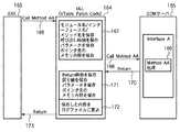
図8は、図7におけるVTable Patchの処理をあらわすタイミングチャートである。説明を簡略化するために、この図ではEXEがCOMサーバ内のInterface AのMethod AAを呼び出す際に、VTable Patchによるログ取得コードがどのように動作するかの例をあらわしている。他のメソッドの場合についても同様の処理が行われることはいうまでもない。 FIG. 8 is a timing chart showing the processing of the VTable Patch in FIG. To simplify the explanation, this figure shows an example of how the log acquisition code by VTable Patch works when EXE calls Method AA of Interface A in the COM server. It goes without saying that the same processing is performed for other methods.
EXE(163)がMethod AAをコールすると(166)、DLL内にあるログ取得コードがモジュール名/インターフェース名/メソッド名をメモリに保存し、呼び出し時刻をメモリに保存し、呼び出し時のパラメータをメモリに保存し、呼び出し時のポインタパラメータの指すメモリ内容を、メモリに保存する(167)。その後DLLは本来呼び出されるはずであった、COMサーバ(165)内のMethod AAをコールする(168)。COMサーバのMethod AA処理(169)が終了し、DLLに制御がリターンすると(170)、DLLはリターン時の時刻をメモリに保存し、戻り値をメモリに保存し、リターン時にポインタパラメータが指すメモリ内容を、メモリに保存する(171)。その後、DLLは保存したログ情報をファイルに書き込み(172)、あたかもCOMサーバのMethod AAが通常通りに終了したかのように、EXEにリターンする(173)。 When EXE (163) calls Method AA (166), the log acquisition code in the DLL saves the module name / interface name / method name in memory, saves the call time in memory, and saves the parameters when calling The memory contents indicated by the pointer parameter at the time of calling are saved in the memory (167). Thereafter, the DLL calls Method AA in the COM server (165), which was supposed to be called (168). When Method AA processing (169) of the COM server is completed and control returns to the DLL (170), the DLL stores the return time in the memory, stores the return value in the memory, and the memory pointed to by the pointer parameter at the time of return The contents are stored in the memory (171). Thereafter, the DLL writes the saved log information to the file (172), and returns to the EXE as if the Method AA of the COM server ended normally (173).
図9は、本実施形態に対応する情報処理装置において実行形式ファイルEXEが実行される場合の動作の一例を示す図である。通常は実行形式のEXE(176)が、COMサーバ-1(179)やCOMサーバ-2(180)内のメソッドを呼び出すが、ここではAPIトレーサと呼ばれるログ取得コードを埋め込み(177)、処理ログを生成している(178)。APIトレーサは、COMサーバ-1(179)やCOMサーバ-2の関数定義を記述したファイル(174)と、どのCOMサーバのどのインターフェースのどのメソッドのvirtual address tableを書き換えてログを取得するかの設定シナリオ(175)を元に動作する。 FIG. 9 is a diagram illustrating an example of an operation when the execution format file EXE is executed in the information processing apparatus corresponding to the present embodiment. Normally, the executable EXE (176) calls a method in the COM server-1 (179) or COM server-2 (180). Here, a log acquisition code called an API tracer is embedded (177), and the processing log (178). The API tracer rewrites the COM server-1 (179) or COM server-2 function definition file (174) and the virtual address table of which interface of which interface of which COM server to acquire the log. It operates based on the setting scenario (175).
図10は、本実施形態に対応する情報処理装置において利用される、関数及びメソッドのパラメータの形式や、戻り値の形式を指示する関数定義ファイルの一例を示す図である。この関数定義ファイルは、図5の関数定義111や図9の関数定義174に対応する。
FIG. 10 is a diagram illustrating an example of a function definition file for instructing the format of the function and method parameters and the format of the return value used in the information processing apparatus corresponding to the present embodiment. This function definition file corresponds to the
関数定義ファイルは、DLL名及び関数/メソッド名を記述し、その関数/メソッドに対する、パラメータ及び戻り値の型が示されている。本実施形態は、この関数定義ファイルによって指示された内容に基づいて、それぞれの関数/メソッドがどのようなパラメータ/戻り値を有しているかが判定され、その内容がログとして取得される。 The function definition file describes the DLL name and the function / method name, and indicates the parameter and return value type for the function / method. In this embodiment, based on the contents instructed by the function definition file, it is determined what parameters / return values each function / method has, and the contents are acquired as a log.
図10において示されたA.DLL内の関数FuncABに対する関数定義は、本発明の実施形態を最もよくあらわすものの一つである。引数には、データの格納先(書込開始アドレス)として示されるポインタpBufと、そのデータのサイズとして示されるdwBufSizeが定義されており、pBufとdwBufSizeとの相関、すなわちpBufに格納されたデータのサイズがdwBufSizeによって指示されているという相関が定義されている。 The function definition for the function FuncAB in A.DLL shown in FIG. 10 is one of the best representations of the embodiment of the present invention. In the argument, a pointer pBuf indicated as the data storage destination (write start address) and dwBufSize indicated as the size of the data are defined. The correlation between pBuf and dwBufSize, that is, the data stored in pBuf A correlation is defined that the size is indicated by dwBufSize.
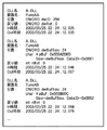
図11は、図10に示した関数定義ファイルを用いて、本発明の情報処理装置において取得されたログの一例を示す図である。それぞれの呼び出しに対して、関数/メソッドが呼び出された時刻、及びその際のパラメータ/戻り値が、ログとして生成される。 FIG. 11 is a diagram showing an example of a log acquired in the information processing apparatus of the present invention using the function definition file shown in FIG. For each call, the time when the function / method is called and the parameters / return values at that time are generated as a log.
図11において示されたA.DLL内の関数FuncABに対する呼び出しのログは、図10の関数定義ファイルと共に、本発明の実施形態の特徴を最もよく表すものの一つである。図10に示した関数定義ファイルに基づいて、FuncABに対する呼び出しの際には、引数としてのpBufの値(0x5034206D)だけでなく、その値が指し示すアドレス上にある、dwBufSize分すなわち24byte分のデータが、通常のログとは別のバイナリログとして保存され、そのバイナリログファイル内に保存された該当するFuncABの呼び出しのID、すなわちDataIDが、追加情報としてログに保存される。 The call log for the function FuncAB in A.DLL shown in FIG. 11 is one of the best features of the embodiment of the present invention together with the function definition file of FIG. Based on the function definition file shown in FIG. 10, when calling to FuncAB, not only the pBuf value (0x5034206D) as an argument but also dwBufSize data, that is, 24 bytes of data on the address indicated by the value is stored. The ID of the corresponding FuncAB call stored in the binary log file, that is, the Data ID, is stored in the log as additional information.
図12は、図11に示したログと共に保存されるバイナリログファイルの実体を一例として示す図である。ここでは、各バイナリログファイルを識別するためのタグとしてDataIDが保存され、そのDataID毎にバイナリデータの本体が保存されている。 FIG. 12 is a diagram illustrating an example of the binary log file stored together with the log illustrated in FIG. 11. Here, DataID is stored as a tag for identifying each binary log file, and the main body of binary data is stored for each DataID.
図10乃至図12に示された関数定義ファイル、ログ、バイナリログは、指示するデータが入力データか出力データか、あるいは戻り値かに依存せずに有効である。例えば、関数からの出力パラメータとしてデータアドレスが戻され、更に関数からの戻り値としてデータサイズが出力された場合にも、同様にデータ本体のログを取得することが可能である。 The function definition file, log, and binary log shown in FIGS. 10 to 12 are valid regardless of whether the data to be indicated is input data, output data, or a return value. For example, even when a data address is returned as an output parameter from a function and a data size is output as a return value from the function, a log of the data body can be obtained in the same manner.
[第1の実施形態]
以上の構成に基づいて、本発明の情報処理装置において実行される処理について説明する。図13は、本実施形態におけるバイナリログの保存にかかわる処理の一例に対応するフローチャートである。
[First Embodiment]
Based on the above configuration, processing executed in the information processing apparatus of the present invention will be described. FIG. 13 is a flowchart corresponding to an example of processing relating to storage of a binary log in the present embodiment.
図13(a)において、設定された関数/メソッドが呼び出されることによって、処理が開始されると(S1301)、本ソフトウェアはDLL名/関数名/呼び出し時の時刻をHDDに保存し(S1302)、その呼び出しに対してのパラメータをHDDに保存する(S1303)。次に本ソフトウェアは、パラメータがメモリアドレスとして定義されているかどうかを、第11図に示した関数定義ファイルに基づいて判断し(S1304)、定義されている場合はバイナリ保存処理(S1305)を行なう。このバイナリ保存処理の詳細は、図13(b)に示すとおりであり、ここでは関数定義のサイズをあらわす引数からデータサイズを取得し(S1314)、ポインタpBufで示されるメモリアドレス(書込開始アドレス)からデータサイズ分に相当するメモリ領域を算出し、算出されたメモリ領域が正しい領域であるかをOSへ問い合わせる(S1315)。正しい領域であると判定された場合のみ、そのサイズ分のデータをメモリから読み込んで(S1316)、DataIDをつけてデータをHDDのバイナリログファイルに保存する(S1317)。一方、正しい領域でないと判定された場合には、バイナリ保存処理をそのまま終了し、対応するデータのバイナリログファイルとしての保存を行わない。パラメータがメモリアドレスとして定義されていない場合には、データ保存処理そのものを行わない。 In FIG. 13A, when the process is started by calling the set function / method (S1301), the software stores the DLL name / function name / calling time in the HDD (S1302). The parameter for the call is saved in the HDD (S1303). Next, the software determines whether or not the parameter is defined as a memory address based on the function definition file shown in FIG. 11 (S1304), and if defined, performs binary storage processing (S1305). . The details of this binary storage processing are as shown in FIG. 13B. Here, the data size is obtained from the argument representing the size of the function definition (S1314), and the memory address (write start address) indicated by the pointer pBuf is obtained. ) To calculate the memory area corresponding to the data size, and inquires of the OS whether the calculated memory area is the correct area (S1315). Only when it is determined that the area is correct, the data corresponding to the size is read from the memory (S1316), and the data is attached to the data and stored in the binary log file of the HDD (S1317). On the other hand, if it is determined that the area is not correct, the binary storage process is terminated as it is, and the corresponding data is not stored as a binary log file. If the parameter is not defined as a memory address, the data storage process itself is not performed.
図13(a)に戻ると、関数内部の処理が終了すると(S1306)、本ソフトウェアはDLL名/関数名/終了時の時刻をHDDに保存し(S1307)、その呼び出しに対してのパラメータ及び戻り値をHDDに保存する(S1308)。次にパラメータがメモリアドレスとして定義されているかどうかを、図11に示した関数定義ファイルに基づいて判定し(S1309)、定義されている場合はバイナリ保存処理(S1310)を行なう。バイナリ保存処理は上述した図13(b)に示す処理と同様である。異常の処理は、評価対象となるプログラムが終了するまで(S1311)続行される。 Returning to FIG. 13 (a), when the internal processing of the function ends (S1306), the software stores the DLL name / function name / end time in the HDD (S1307). The return value is stored in the HDD (S1308). Next, whether or not the parameter is defined as a memory address is determined based on the function definition file shown in FIG. 11 (S1309), and if defined, binary storage processing (S1310) is performed. The binary storage process is the same as the process shown in FIG. The abnormality process is continued until the program to be evaluated ends (S1311).
以上のように、本実施形態に対応する本発明によれば、データを書き込むべきメモリアドレスとデータサイズに基づいてデータの書込領域が正しい領域であるかどうかを事前に問い合わせ、正しい領域との判定の上で書込を行うので、誤って不正領域にデータが書き込まれることがなくなり、不正領域にデータが書き込まれた場合に生ずるはずの例外処理を未然に防止することが可能となる。 As described above, according to the present invention corresponding to the present embodiment, an inquiry is made in advance as to whether or not the data writing area is a correct area based on the memory address and the data size to which data is to be written. Since the writing is performed based on the determination, data is not erroneously written to the illegal area, and it is possible to prevent an exception process that should occur when data is written to the illegal area.
[第2の実施形態]
上記の第1の実施形態では、保存するバイナリ領域全体として正しい領域でなければバイナリデータの保存処理を行わせないようにしていたが、本実施形態では、バイナリ領域に不正な領域が一部存在していた場合であっても、不正なメモリアドレスが存在する直前までのバイナリデータを保存可能とする。
[Second Embodiment]
In the first embodiment, the binary data is not saved unless the entire binary area to be saved is correct. However, in this embodiment, there are some illegal areas in the binary area. Even in such a case, binary data up to immediately before an invalid memory address can be stored.
以下、本発明の情報処理装置において実行される処理について説明する。図14は、本実施形態におけるバイナリログの保存にかかわる処理の一例に対応するフローチャートである。 Hereinafter, processing executed in the information processing apparatus of the present invention will be described. FIG. 14 is a flowchart corresponding to an example of processing relating to storage of a binary log in the present embodiment.
図14(a)において、設定された関数/メソッドが呼び出されることによって、処理が開始されると(S1401)、本ソフトウェアはDLL名/関数名/呼び出し時の時刻をHDDに保存し(S1402)、その呼び出しに対してのパラメータをHDDに保存する(S1403)。次に本ソフトウェアは、パラメータがメモリアドレスとして定義されているかどうかを、図11に示した関数定義ファイルに基づいて判断し(S1404)、定義されている場合はバイナリ保存処理(S1405)を行なう。 In FIG. 14A, when the processing is started by calling the set function / method (S1401), the software stores the DLL name / function name / calling time in the HDD (S1402). The parameter for the call is stored in the HDD (S1403). Next, the software determines whether or not the parameter is defined as a memory address based on the function definition file shown in FIG. 11 (S1404), and if defined, performs a binary storage process (S1405).
ここでバイナリ保存処理の詳細は、図14(b)に示す通りであり、ここにおいて関数定義のサイズをあらわす引数からデータサイズを取得し(S1414)、データサイズ分のループ処理(S1415乃至S1418)でデータ領域を、1バイト単位に正しい領域に書き込まれるか否かの判定を行なう。取得を行なうメモリアドレスの先頭からnバイト目の1バイト分のメモリ領域が正しい領域であるか否かをOSへ問い合わせる(S1417)。正しい領域であると判定された場合のみ、次のデータ領域の判断を行なうため、nをインクリメントする(S1417))。不正な領域であると判定された場合には、そこ時点でデータ領域の判定を終了する。 The details of the binary storage process are as shown in FIG. 14B. Here, the data size is acquired from the argument representing the size of the function definition (S1414), and the loop process for the data size (S1415 to S1418). Then, it is determined whether or not the data area is written in the correct area in units of 1 byte. An inquiry is made to the OS as to whether or not the memory area for the first byte of the nth byte from the beginning of the memory address to be acquired is a correct area (S1417). Only when it is determined that the area is correct, n is incremented in order to determine the next data area (S1417). If it is determined that the area is an illegal area, the determination of the data area ends at that point.
S1415〜S1418までのループ処理が終了すると、正しい領域のバイト数はnとなるので、nが0であるか否かにより正しい領域があるか否かを判定し(S1419)、正しい領域があったと判定された場合には、そのサイズ分である、nバイトのデータをメモリ領域の先頭から読み込んで(S1420)、DataIDをつけてデータをHDDのバイナリログファイルに保存する(S1421)。一方、nが0であり、全領域が誤りであると判定された場合には、データの保存を行わずにバイナリ保存処理を終了する。また、パラメータがメモリアドレスとして定義されていない場合には、データ保存処理そのものを行わない。 When the loop processing from S1415 to S1418 is completed, the number of bytes in the correct area is n. Therefore, it is determined whether or not there is a correct area depending on whether n is 0 (S1419). If it is determined, n bytes of data corresponding to the size are read from the beginning of the memory area (S1420), and the data is attached to the HDD and stored in the binary log file of the HDD (S1421). On the other hand, if n is 0 and it is determined that the entire area is in error, the binary storage process is terminated without storing the data. If the parameter is not defined as a memory address, the data storage process itself is not performed.
関数内部の処理が終了すると(S1406)、本ソフトウェアはDLL名/関数名/終了時の時刻をHDDに保存し(S1407)、その呼び出しに対してのパラメータ及び戻り値をHDDに保存する(S1408)。次に、パラメータがメモリアドレスとして定義されているかどうかを、図11に示した関数定義ファイルに基づいて判断し(S1409)、定義されている場合はバイナリ保存処理を行なう。バイナリ保存処理は、上述の図14(b)における処理と同様である。以上の処理は、評価対象となるプログラムが終了するまで(S1411)続行される。 When the processing inside the function ends (S1406), the software stores the DLL name / function name / end time in the HDD (S1407), and saves the parameters and return value for the call in the HDD (S1408). ). Next, it is determined whether or not the parameter is defined as a memory address based on the function definition file shown in FIG. 11 (S1409). If defined, binary storage processing is performed. The binary storage process is the same as the process in FIG. The above processing is continued until the program to be evaluated ends (S1411).
以上によれば、保存するバイナリ領域に不正な領域が一部存在していた場合であっても、不正なメモリアドレスが存在する直前までのバイナリデータを保存することができる。 According to the above, even if there is a part of an illegal area in the binary area to be saved, binary data up to immediately before an illegal memory address can be saved.
[その他の実施形態]
なお、本発明は、複数の機器(例えばホストコンピュータ、インタフェイス機器、リーダ、プリンタなど)から構成されるシステムに適用しても、一つの機器からなる装置(例えば、複写機、ファクシミリ装置など)に適用してもよい。
[Other Embodiments]
Note that the present invention can be applied to a system including a plurality of devices (for example, a host computer, an interface device, a reader, and a printer), and a device (for example, a copying machine and a facsimile device) including a single device. You may apply to.
また、本発明の目的は、前述した実施形態の機能を実現するソフトウェアのプログラムコードを記録した記憶媒体(または記録媒体)を、システムあるいは装置に供給し、そのシステムあるいは装置のコンピュータ(またはCPUやMPU)が記憶媒体に格納されたプログラムコードを読み出し実行することによっても、達成されることは言うまでもない。この場合、記憶媒体から読み出されたプログラムコード自体が前述した実施形態の機能を実現することになり、そのプログラムコードを記憶した記憶媒体は本発明を構成することになる。また、コンピュータが読み出したプログラムコードを実行することにより、前述した実施形態の機能が実現されるだけでなく、そのプログラムコードの指示に基づき、コンピュータ上で稼働しているオペレーティングシステム(OS)などが実際の処理の一部または全部を行い、その処理によって前述した実施形態の機能が実現される場合も含まれることは言うまでもない。 Also, an object of the present invention is to supply a storage medium (or recording medium) that records a program code of software that realizes the functions of the above-described embodiments to a system or apparatus, and to computer (or CPU or CPU) of the system or apparatus. Needless to say, this can also be achieved by the MPU) reading and executing the program code stored in the storage medium. In this case, the program code itself read from the storage medium realizes the functions of the above-described embodiments, and the storage medium storing the program code constitutes the present invention. Further, by executing the program code read by the computer, not only the functions of the above-described embodiments are realized, but also an operating system (OS) running on the computer based on the instruction of the program code. It goes without saying that a case where the function of the above-described embodiment is realized by performing part or all of the actual processing and the processing is included.
さらに、記憶媒体から読み出されたプログラムコードが、コンピュータに挿入された機能拡張カードやコンピュータに接続された機能拡張ユニットに備わるメモリに書込まれた後、そのプログラムコードの指示に基づき、その機能拡張カードや機能拡張ユニットに備わるCPUなどが実際の処理の一部または全部を行い、その処理によって前述した実施形態の機能が実現される場合も含まれることは言うまでもない。 Furthermore, after the program code read from the storage medium is written into a memory provided in a function expansion card inserted into the computer or a function expansion unit connected to the computer, the function is determined based on the instruction of the program code. It goes without saying that the CPU or the like provided in the expansion card or the function expansion unit performs part or all of the actual processing and the functions of the above-described embodiments are realized by the processing.
Claims (10)
前記第3のモジュールが、
前記ログを取得するログ取得手段と、
取得された前記ログから、前記第2のモジュール内の関数の引数として含まれている、バイナリデータの格納されている領域の先頭を表す書込開始アドレスと、データサイズとの情報を取得する情報取得手段と、
前記書込開始アドレスと前記データサイズとから、前記バイナリデータの書き込まれている領域を決定する領域決定手段と、
決定された前記領域へのアクセスが許可されているか否かをOSに問い合わせる問い合わせ手段と、
前記問い合わせの結果により前記決定された領域のうち一部の領域のみのアクセスが許可されている場合に、前記一部の領域に対応する前記バイナリデータの一部のメモリへの書込を行う書込制御手段と
を備えることを特徴とする情報処理装置。 The first module, the second module, and a call from the first module to a function in the second module are mediated, and a processing log in the second module corresponding to the call is acquired. A third module for executing an information processing apparatus,
The third module is
Log acquisition means for acquiring the log;
Information for acquiring information on the write start address and the data size, which is included as an argument of the function in the second module and indicates the head of the area where binary data is stored , from the acquired log Acquisition means;
From said data size and the write start address, and area determination means for determining Tei Ru region written with the binary data,
Or allowed determined access to the area Tei Luca whether the inquiry means for inquiring the OS,
Writing of writing of if access only a portion of the area of said is the determined by the result of the inquiry region is permitted, to a portion of the memory of the binary data corresponding to the partial region An information processing apparatus comprising:
前記第3のモジュールが、
前記ログを取得するログ取得工程と、
取得された前記ログから、前記第2のモジュール内の関数の引数として含まれている、バイナリデータの格納されている領域の先頭を表す書込開始アドレスと、データサイズとの情報を取得する情報取得工程と、
前記書込開始アドレスと前記データサイズとから、前記バイナリデータの書き込まれている領域を決定する領域決定工程と、
決定された前記領域へのアクセスが許可されているか否かをOSに問い合わせる問い合わせ工程と、
前記問い合わせの結果により前記決定された領域のうち一部の領域のみのアクセスが許可されている場合に、前記一部の領域に対応する前記バイナリデータの一部のメモリへの書込を行う書込制御工程と
を実行することを特徴とする情報処理装置の制御方法。 The first module, the second module, and a call from the first module to a function in the second module are mediated, and a processing log in the second module corresponding to the call is acquired. A third module for controlling the information processing apparatus,
The third module is
A log acquisition step for acquiring the log;
Information for acquiring information on the write start address and the data size, which is included as an argument of the function in the second module and indicates the head of the area where binary data is stored , from the acquired log Acquisition process;
From said data size and the write start address, and area determining step of determining the written Tei Ru regions of the binary data,
Or allowed determined access to the area Tei Luca whether an inquiry step of querying the OS,
Writing of writing of if access only a portion of the area of said is the determined by the result of the inquiry region is permitted, to a portion of the memory of the binary data corresponding to the partial region A control method for an information processing apparatus, wherein the control method is executed.
Priority Applications (2)
| Application Number | Priority Date | Filing Date | Title |
|---|---|---|---|
| JP2004364783A JP4681868B2 (en) | 2004-12-16 | 2004-12-16 | Information processing apparatus and control method therefor, computer program, and storage medium |
| US11/300,391 US7743228B2 (en) | 2004-12-16 | 2005-12-14 | Information processing apparatus and method for obtaining software processing log |
Applications Claiming Priority (1)
| Application Number | Priority Date | Filing Date | Title |
|---|---|---|---|
| JP2004364783A JP4681868B2 (en) | 2004-12-16 | 2004-12-16 | Information processing apparatus and control method therefor, computer program, and storage medium |
Publications (3)
| Publication Number | Publication Date |
|---|---|
| JP2006172206A JP2006172206A (en) | 2006-06-29 |
| JP2006172206A5 JP2006172206A5 (en) | 2008-02-14 |
| JP4681868B2 true JP4681868B2 (en) | 2011-05-11 |
Family
ID=36597183
Family Applications (1)
| Application Number | Title | Priority Date | Filing Date |
|---|---|---|---|
| JP2004364783A Expired - Fee Related JP4681868B2 (en) | 2004-12-16 | 2004-12-16 | Information processing apparatus and control method therefor, computer program, and storage medium |
Country Status (2)
| Country | Link |
|---|---|
| US (1) | US7743228B2 (en) |
| JP (1) | JP4681868B2 (en) |
Families Citing this family (14)
| Publication number | Priority date | Publication date | Assignee | Title |
|---|---|---|---|---|
| KR20040028469A (en) | 2002-09-30 | 2004-04-03 | 엘지전자 주식회사 | Method for managing a defect area on optical disc write once |
| US7233550B2 (en) | 2002-09-30 | 2007-06-19 | Lg Electronics Inc. | Write-once optical disc, and method and apparatus for recording management information on write-once optical disc |
| CA2508454C (en) * | 2002-12-11 | 2013-01-08 | Lg Electronics Inc. | Method of managing overwrite and method of recording management information on an optical disc write once |
| TWI314315B (en) | 2003-01-27 | 2009-09-01 | Lg Electronics Inc | Optical disc of write once type, method, and apparatus for managing defect information on the optical disc |
| KR20050119703A (en) * | 2003-05-09 | 2005-12-21 | 엘지전자 주식회사 | Recording medium having data structure for managing at least a data area of the recording medium and recording and reproducing methods and apparatuses |
| BRPI0410198A (en) | 2003-05-09 | 2006-05-23 | Lg Electronics Inc | physical recording medium, method of managing disk management information, method of retrieving management information from physical recording medium, apparatus for managing disk management information on physical recording medium, and apparatus for retrieving management information from of the physical recording medium |
| KR20050009031A (en) * | 2003-07-15 | 2005-01-24 | 엘지전자 주식회사 | Method for recording management information on optical disc write once |
| US7313065B2 (en) | 2003-08-05 | 2007-12-25 | Lg Electronics Inc. | Write-once optical disc, and method and apparatus for recording/reproducing management information on/from optical disc |
| BRPI0414213A (en) * | 2003-09-08 | 2006-10-31 | Lg Electronics Inc | method and apparatus of managing physical recording medium and physical recording medium |
| MXPA06002621A (en) * | 2003-09-08 | 2006-06-05 | Lg Electronics Inc | Write-once optical disc, and method and apparatus for management information thereon. |
| WO2005024793A2 (en) * | 2003-09-08 | 2005-03-17 | Lg Electronics Inc. | Write-once optical disc, and method and apparatus for recording management information thereon |
| JP4681923B2 (en) * | 2005-04-01 | 2011-05-11 | キヤノン株式会社 | Information processing apparatus and control method therefor, computer program, and storage medium |
| JP4046753B2 (en) | 2006-06-22 | 2008-02-13 | 株式会社コナミデジタルエンタテインメント | Line shape processing apparatus, line shape processing method, and program |
| US8578393B1 (en) * | 2008-06-18 | 2013-11-05 | Alert Logic, Inc. | Log message collection employing on-demand loading of message translation libraries |
Citations (3)
| Publication number | Priority date | Publication date | Assignee | Title |
|---|---|---|---|---|
| JP2004021429A (en) * | 2002-06-13 | 2004-01-22 | Fujitsu Ltd | Compiler program equipped with dummy argument multiple violation detection function, its recording medium, and compiler device |
| JP2004038314A (en) * | 2002-06-28 | 2004-02-05 | Canon Inc | Log acquiring method and program, and storage medium |
| JP2004318524A (en) * | 2003-04-16 | 2004-11-11 | Seiko Epson Corp | Device driver controlling module, method and program, and device driver |
Family Cites Families (15)
| Publication number | Priority date | Publication date | Assignee | Title |
|---|---|---|---|---|
| JPH0981411A (en) * | 1995-09-20 | 1997-03-28 | Fujitsu Ltd | Compiler |
| US6219728B1 (en) * | 1996-04-22 | 2001-04-17 | Nortel Networks Limited | Method and apparatus for allocating shared memory resources among a plurality of queues each having a threshold value therefor |
| US6272611B1 (en) * | 1999-02-09 | 2001-08-07 | Yu-Te Wu | Computer data storage medium having a virtual disk drive and memory management method therefor |
| JP3763992B2 (en) * | 1999-03-30 | 2006-04-05 | 富士通株式会社 | Data processing apparatus and recording medium |
| US7543290B2 (en) * | 2001-04-11 | 2009-06-02 | Mellanox Technologies Ltd. | Multiple queue pair access with single doorbell |
| US20030061273A1 (en) * | 2001-09-24 | 2003-03-27 | Intel Corporation | Extended content storage method and apparatus |
| US6792504B2 (en) * | 2002-01-25 | 2004-09-14 | Seagate Technology Llc | Read on arrival scheme for a disc drive |
| US7565509B2 (en) * | 2002-04-17 | 2009-07-21 | Microsoft Corporation | Using limits on address translation to control access to an addressable entity |
| US7188279B2 (en) | 2002-06-28 | 2007-03-06 | Canon Kabushiki Kaisha | Method, program, and storage medium for acquiring logs |
| JP4125053B2 (en) | 2002-06-28 | 2008-07-23 | キヤノン株式会社 | Log acquisition method |
| JP2004213435A (en) * | 2003-01-07 | 2004-07-29 | Hitachi Ltd | Storage device system |
| US7299379B2 (en) * | 2003-06-27 | 2007-11-20 | Intel Corporation | Maintaining cache integrity by recording write addresses in a log |
| US7210014B2 (en) * | 2004-05-27 | 2007-04-24 | Microsoft Corporation | Alternative methods in memory protection |
| US7353301B2 (en) * | 2004-10-29 | 2008-04-01 | Intel Corporation | Methodology and apparatus for implementing write combining |
| US7297584B2 (en) * | 2005-10-07 | 2007-11-20 | Samsung Electronics Co., Ltd. | Methods of fabricating semiconductor devices having a dual stress liner |
-
2004
- 2004-12-16 JP JP2004364783A patent/JP4681868B2/en not_active Expired - Fee Related
-
2005
- 2005-12-14 US US11/300,391 patent/US7743228B2/en not_active Expired - Fee Related
Patent Citations (3)
| Publication number | Priority date | Publication date | Assignee | Title |
|---|---|---|---|---|
| JP2004021429A (en) * | 2002-06-13 | 2004-01-22 | Fujitsu Ltd | Compiler program equipped with dummy argument multiple violation detection function, its recording medium, and compiler device |
| JP2004038314A (en) * | 2002-06-28 | 2004-02-05 | Canon Inc | Log acquiring method and program, and storage medium |
| JP2004318524A (en) * | 2003-04-16 | 2004-11-11 | Seiko Epson Corp | Device driver controlling module, method and program, and device driver |
Also Published As
| Publication number | Publication date |
|---|---|
| US7743228B2 (en) | 2010-06-22 |
| JP2006172206A (en) | 2006-06-29 |
| US20060136134A1 (en) | 2006-06-22 |
Similar Documents
| Publication | Publication Date | Title |
|---|---|---|
| US7743228B2 (en) | Information processing apparatus and method for obtaining software processing log | |
| US9400667B2 (en) | String cache file for optimizing memory usage in a Java virtual machine | |
| US9286048B2 (en) | Apparatus, non-transitory computer readable information recording medium and information recording method that determine identification information for identifying a program that has issued a use request | |
| US7086034B2 (en) | Method, program, and storage medium for acquiring logs | |
| US11474855B2 (en) | Information processing apparatus, information processing method, and storage medium | |
| US7188279B2 (en) | Method, program, and storage medium for acquiring logs | |
| JP4280749B2 (en) | Log acquisition method, program, and storage medium | |
| US7426660B2 (en) | Method, program, and storage medium for acquiring logs | |
| US7886279B2 (en) | Information processing apparatus, control method therefor, computer program, and storage medium | |
| JP4125055B2 (en) | Log acquisition method | |
| US11809881B2 (en) | Target process injection prior to execution of marker libraries | |
| US7519868B2 (en) | Information processing apparatus, information processing method, computer program, and storage medium | |
| JP4125053B2 (en) | Log acquisition method | |
| JP4125056B2 (en) | Log acquisition method | |
| US8191050B2 (en) | Information processor, control method therefor, computer program and storage medium | |
| US8042176B2 (en) | Computer readable medium on which is stored a program for preventing the unauthorized use of program data | |
| JP2006031248A (en) | Software evaluation system for generating log by hooking function call | |
| JP3848171B2 (en) | Computer simulation program, processor model verification method, and computer simulation method | |
| JP4125054B2 (en) | Log acquisition method | |
| EP2169555A1 (en) | Cache controller, cache control method and cache control program | |
| CN112631720A (en) | Memory control method, medium, and device | |
| JP2006040021A (en) | Software evaluation system for acquiring function log and detecting color output data from color object used | |
| JP2006040020A (en) | Software evaluation system for acquiring function log and detecting color output data from handle parameter | |
| JP2006040216A (en) | Software evaluation system for acquiring function log and detecting color output data of bit map |
Legal Events
| Date | Code | Title | Description |
|---|---|---|---|
| A521 | Request for written amendment filed |
Free format text: JAPANESE INTERMEDIATE CODE: A523 Effective date: 20071217 |
|
| A621 | Written request for application examination |
Free format text: JAPANESE INTERMEDIATE CODE: A621 Effective date: 20071217 |
|
| RD03 | Notification of appointment of power of attorney |
Free format text: JAPANESE INTERMEDIATE CODE: A7423 Effective date: 20071217 |
|
| A131 | Notification of reasons for refusal |
Free format text: JAPANESE INTERMEDIATE CODE: A131 Effective date: 20091218 |
|
| A521 | Request for written amendment filed |
Free format text: JAPANESE INTERMEDIATE CODE: A523 Effective date: 20100216 |
|
| A131 | Notification of reasons for refusal |
Free format text: JAPANESE INTERMEDIATE CODE: A131 Effective date: 20100702 |
|
| A521 | Request for written amendment filed |
Free format text: JAPANESE INTERMEDIATE CODE: A523 Effective date: 20100831 |
|
| TRDD | Decision of grant or rejection written | ||
| A01 | Written decision to grant a patent or to grant a registration (utility model) |
Free format text: JAPANESE INTERMEDIATE CODE: A01 Effective date: 20110131 |
|
| A01 | Written decision to grant a patent or to grant a registration (utility model) |
Free format text: JAPANESE INTERMEDIATE CODE: A01 |
|
| A61 | First payment of annual fees (during grant procedure) |
Free format text: JAPANESE INTERMEDIATE CODE: A61 Effective date: 20110207 |
|
| R150 | Certificate of patent or registration of utility model |
Free format text: JAPANESE INTERMEDIATE CODE: R150 |
|
| FPAY | Renewal fee payment (event date is renewal date of database) |
Free format text: PAYMENT UNTIL: 20140210 Year of fee payment: 3 |
|
| LAPS | Cancellation because of no payment of annual fees |