JP4680511B2 - How to remove contaminants from gases - Google Patents
How to remove contaminants from gases Download PDFInfo
- Publication number
- JP4680511B2 JP4680511B2 JP2003569553A JP2003569553A JP4680511B2 JP 4680511 B2 JP4680511 B2 JP 4680511B2 JP 2003569553 A JP2003569553 A JP 2003569553A JP 2003569553 A JP2003569553 A JP 2003569553A JP 4680511 B2 JP4680511 B2 JP 4680511B2
- Authority
- JP
- Japan
- Prior art keywords
- carbon dioxide
- purified
- catalyst
- application
- purified carbon
- Prior art date
- Legal status (The legal status is an assumption and is not a legal conclusion. Google has not performed a legal analysis and makes no representation as to the accuracy of the status listed.)
- Expired - Fee Related
Links
- 239000000356 contaminant Substances 0.000 title claims description 77
- 239000007789 gas Substances 0.000 title description 24
- CURLTUGMZLYLDI-UHFFFAOYSA-N Carbon dioxide Chemical compound O=C=O CURLTUGMZLYLDI-UHFFFAOYSA-N 0.000 claims description 565
- 239000001569 carbon dioxide Substances 0.000 claims description 281
- 229910002092 carbon dioxide Inorganic materials 0.000 claims description 281
- 239000002245 particle Substances 0.000 claims description 108
- 238000000034 method Methods 0.000 claims description 68
- 239000003054 catalyst Substances 0.000 claims description 56
- 239000007788 liquid Substances 0.000 claims description 38
- 238000000746 purification Methods 0.000 claims description 29
- QVGXLLKOCUKJST-UHFFFAOYSA-N atomic oxygen Chemical compound [O] QVGXLLKOCUKJST-UHFFFAOYSA-N 0.000 claims description 18
- 230000001590 oxidative effect Effects 0.000 claims description 18
- 239000001301 oxygen Substances 0.000 claims description 18
- 229910052760 oxygen Inorganic materials 0.000 claims description 18
- 239000007800 oxidant agent Substances 0.000 claims description 16
- 238000001179 sorption measurement Methods 0.000 claims description 11
- 238000004821 distillation Methods 0.000 claims description 10
- XLYOFNOQVPJJNP-UHFFFAOYSA-N water Substances O XLYOFNOQVPJJNP-UHFFFAOYSA-N 0.000 claims description 10
- 239000004065 semiconductor Substances 0.000 claims description 8
- 238000000149 argon plasma sintering Methods 0.000 claims description 7
- 238000012545 processing Methods 0.000 claims description 7
- 238000010521 absorption reaction Methods 0.000 claims description 6
- 238000000926 separation method Methods 0.000 claims description 6
- 238000001816 cooling Methods 0.000 claims description 5
- 238000002156 mixing Methods 0.000 claims description 4
- 238000010438 heat treatment Methods 0.000 claims description 3
- 238000003860 storage Methods 0.000 claims description 2
- 239000003570 air Substances 0.000 claims 2
- 238000004064 recycling Methods 0.000 claims 2
- 238000005201 scrubbing Methods 0.000 claims 2
- 238000007254 oxidation reaction Methods 0.000 description 42
- 230000003647 oxidation Effects 0.000 description 40
- 230000003197 catalytic effect Effects 0.000 description 37
- 239000000047 product Substances 0.000 description 35
- 239000007787 solid Substances 0.000 description 22
- BASFCYQUMIYNBI-UHFFFAOYSA-N platinum Chemical group [Pt] BASFCYQUMIYNBI-UHFFFAOYSA-N 0.000 description 17
- 238000004140 cleaning Methods 0.000 description 16
- 239000003463 adsorbent Substances 0.000 description 15
- 229930195733 hydrocarbon Natural products 0.000 description 14
- 150000002430 hydrocarbons Chemical class 0.000 description 14
- 239000000443 aerosol Substances 0.000 description 12
- 239000000463 material Substances 0.000 description 12
- 239000012071 phase Substances 0.000 description 11
- 239000012530 fluid Substances 0.000 description 10
- VNWKTOKETHGBQD-UHFFFAOYSA-N methane Chemical compound C VNWKTOKETHGBQD-UHFFFAOYSA-N 0.000 description 10
- 230000008569 process Effects 0.000 description 10
- 239000012808 vapor phase Substances 0.000 description 10
- 229910052751 metal Inorganic materials 0.000 description 9
- 239000002184 metal Substances 0.000 description 9
- 239000002244 precipitate Substances 0.000 description 9
- KDLHZDBZIXYQEI-UHFFFAOYSA-N Palladium Chemical compound [Pd] KDLHZDBZIXYQEI-UHFFFAOYSA-N 0.000 description 8
- 238000009826 distribution Methods 0.000 description 8
- OKTJSMMVPCPJKN-UHFFFAOYSA-N Carbon Chemical compound [C] OKTJSMMVPCPJKN-UHFFFAOYSA-N 0.000 description 7
- 238000006243 chemical reaction Methods 0.000 description 7
- 239000003814 drug Substances 0.000 description 7
- 229940079593 drug Drugs 0.000 description 7
- 238000004519 manufacturing process Methods 0.000 description 7
- 229910052697 platinum Inorganic materials 0.000 description 7
- 239000012855 volatile organic compound Substances 0.000 description 7
- 238000009833 condensation Methods 0.000 description 6
- 230000005494 condensation Effects 0.000 description 6
- 239000012535 impurity Substances 0.000 description 6
- 239000000203 mixture Substances 0.000 description 6
- 239000000843 powder Substances 0.000 description 6
- 239000000243 solution Substances 0.000 description 6
- PNEYBMLMFCGWSK-UHFFFAOYSA-N aluminium oxide Inorganic materials [O-2].[O-2].[O-2].[Al+3].[Al+3] PNEYBMLMFCGWSK-UHFFFAOYSA-N 0.000 description 5
- 230000007423 decrease Effects 0.000 description 5
- 239000003921 oil Substances 0.000 description 5
- 239000004215 Carbon black (E152) Substances 0.000 description 4
- 238000005054 agglomeration Methods 0.000 description 4
- 230000002776 aggregation Effects 0.000 description 4
- 238000013459 approach Methods 0.000 description 4
- 230000008901 benefit Effects 0.000 description 4
- 150000008282 halocarbons Chemical class 0.000 description 4
- 239000007791 liquid phase Substances 0.000 description 4
- 229910052763 palladium Inorganic materials 0.000 description 4
- 239000000376 reactant Substances 0.000 description 4
- 230000009467 reduction Effects 0.000 description 4
- 239000000126 substance Substances 0.000 description 4
- 239000002699 waste material Substances 0.000 description 4
- OTMSDBZUPAUEDD-UHFFFAOYSA-N Ethane Chemical compound CC OTMSDBZUPAUEDD-UHFFFAOYSA-N 0.000 description 3
- 230000015572 biosynthetic process Effects 0.000 description 3
- 239000003990 capacitor Substances 0.000 description 3
- 235000011089 carbon dioxide Nutrition 0.000 description 3
- 239000000919 ceramic Substances 0.000 description 3
- 230000003247 decreasing effect Effects 0.000 description 3
- 238000000151 deposition Methods 0.000 description 3
- 239000006260 foam Substances 0.000 description 3
- 229910052736 halogen Inorganic materials 0.000 description 3
- VUZPPFZMUPKLLV-UHFFFAOYSA-N methane;hydrate Chemical compound C.O VUZPPFZMUPKLLV-UHFFFAOYSA-N 0.000 description 3
- 230000003287 optical effect Effects 0.000 description 3
- 239000008188 pellet Substances 0.000 description 3
- 229920002120 photoresistant polymer Polymers 0.000 description 3
- 239000007790 solid phase Substances 0.000 description 3
- 238000000859 sublimation Methods 0.000 description 3
- 230000008022 sublimation Effects 0.000 description 3
- 238000000194 supercritical-fluid extraction Methods 0.000 description 3
- 238000011144 upstream manufacturing Methods 0.000 description 3
- XKRFYHLGVUSROY-UHFFFAOYSA-N Argon Chemical compound [Ar] XKRFYHLGVUSROY-UHFFFAOYSA-N 0.000 description 2
- IJGRMHOSHXDMSA-UHFFFAOYSA-N Atomic nitrogen Chemical compound N#N IJGRMHOSHXDMSA-UHFFFAOYSA-N 0.000 description 2
- 240000007124 Brassica oleracea Species 0.000 description 2
- UGFAIRIUMAVXCW-UHFFFAOYSA-N Carbon monoxide Chemical compound [O+]#[C-] UGFAIRIUMAVXCW-UHFFFAOYSA-N 0.000 description 2
- MHAJPDPJQMAIIY-UHFFFAOYSA-N Hydrogen peroxide Chemical compound OO MHAJPDPJQMAIIY-UHFFFAOYSA-N 0.000 description 2
- XEEYBQQBJWHFJM-UHFFFAOYSA-N Iron Chemical compound [Fe] XEEYBQQBJWHFJM-UHFFFAOYSA-N 0.000 description 2
- PXHVJJICTQNCMI-UHFFFAOYSA-N Nickel Chemical compound [Ni] PXHVJJICTQNCMI-UHFFFAOYSA-N 0.000 description 2
- GQPLMRYTRLFLPF-UHFFFAOYSA-N Nitrous Oxide Chemical compound [O-][N+]#N GQPLMRYTRLFLPF-UHFFFAOYSA-N 0.000 description 2
- 239000002253 acid Substances 0.000 description 2
- 238000004458 analytical method Methods 0.000 description 2
- 239000010953 base metal Substances 0.000 description 2
- 235000013361 beverage Nutrition 0.000 description 2
- 229910002091 carbon monoxide Inorganic materials 0.000 description 2
- 230000015556 catabolic process Effects 0.000 description 2
- 230000006835 compression Effects 0.000 description 2
- 238000007906 compression Methods 0.000 description 2
- 238000010276 construction Methods 0.000 description 2
- 238000011109 contamination Methods 0.000 description 2
- 239000000498 cooling water Substances 0.000 description 2
- 238000006731 degradation reaction Methods 0.000 description 2
- 230000008021 deposition Effects 0.000 description 2
- 238000013461 design Methods 0.000 description 2
- 238000010586 diagram Methods 0.000 description 2
- OSVXSBDYLRYLIG-UHFFFAOYSA-N dioxidochlorine(.) Chemical compound O=Cl=O OSVXSBDYLRYLIG-UHFFFAOYSA-N 0.000 description 2
- 238000001035 drying Methods 0.000 description 2
- 238000001704 evaporation Methods 0.000 description 2
- 230000008020 evaporation Effects 0.000 description 2
- 239000011261 inert gas Substances 0.000 description 2
- 230000003993 interaction Effects 0.000 description 2
- 239000002808 molecular sieve Substances 0.000 description 2
- 239000002105 nanoparticle Substances 0.000 description 2
- 238000006068 polycondensation reaction Methods 0.000 description 2
- 239000011148 porous material Substances 0.000 description 2
- 238000001556 precipitation Methods 0.000 description 2
- 229920006395 saturated elastomer Polymers 0.000 description 2
- URGAHOPLAPQHLN-UHFFFAOYSA-N sodium aluminosilicate Chemical compound [Na+].[Al+3].[O-][Si]([O-])=O.[O-][Si]([O-])=O URGAHOPLAPQHLN-UHFFFAOYSA-N 0.000 description 2
- 239000002904 solvent Substances 0.000 description 2
- 238000004808 supercritical fluid chromatography Methods 0.000 description 2
- 239000004155 Chlorine dioxide Substances 0.000 description 1
- CBENFWSGALASAD-UHFFFAOYSA-N Ozone Chemical compound [O-][O+]=O CBENFWSGALASAD-UHFFFAOYSA-N 0.000 description 1
- KJTLSVCANCCWHF-UHFFFAOYSA-N Ruthenium Chemical compound [Ru] KJTLSVCANCCWHF-UHFFFAOYSA-N 0.000 description 1
- VYPSYNLAJGMNEJ-UHFFFAOYSA-N Silicium dioxide Chemical compound O=[Si]=O VYPSYNLAJGMNEJ-UHFFFAOYSA-N 0.000 description 1
- CKUAXEQHGKSLHN-UHFFFAOYSA-N [C].[N] Chemical compound [C].[N] CKUAXEQHGKSLHN-UHFFFAOYSA-N 0.000 description 1
- 150000001338 aliphatic hydrocarbons Chemical class 0.000 description 1
- 229910052786 argon Inorganic materials 0.000 description 1
- 238000009835 boiling Methods 0.000 description 1
- 229910052799 carbon Inorganic materials 0.000 description 1
- CREMABGTGYGIQB-UHFFFAOYSA-N carbon carbon Chemical compound C.C CREMABGTGYGIQB-UHFFFAOYSA-N 0.000 description 1
- 239000011203 carbon fibre reinforced carbon Substances 0.000 description 1
- 238000012993 chemical processing Methods 0.000 description 1
- 235000019398 chlorine dioxide Nutrition 0.000 description 1
- 230000003749 cleanliness Effects 0.000 description 1
- 239000000567 combustion gas Substances 0.000 description 1
- 238000002485 combustion reaction Methods 0.000 description 1
- 239000010725 compressor oil Substances 0.000 description 1
- 239000004035 construction material Substances 0.000 description 1
- 238000005336 cracking Methods 0.000 description 1
- 238000000354 decomposition reaction Methods 0.000 description 1
- 230000006837 decompression Effects 0.000 description 1
- 230000001419 dependent effect Effects 0.000 description 1
- 230000008034 disappearance Effects 0.000 description 1
- 238000005203 dry scrubbing Methods 0.000 description 1
- 230000000694 effects Effects 0.000 description 1
- 229920001971 elastomer Polymers 0.000 description 1
- 239000000806 elastomer Substances 0.000 description 1
- 239000013536 elastomeric material Substances 0.000 description 1
- 238000005265 energy consumption Methods 0.000 description 1
- 239000000835 fiber Substances 0.000 description 1
- 238000001914 filtration Methods 0.000 description 1
- 239000012467 final product Substances 0.000 description 1
- 239000000295 fuel oil Substances 0.000 description 1
- 230000005484 gravity Effects 0.000 description 1
- -1 halogen acids Chemical class 0.000 description 1
- 150000002366 halogen compounds Chemical class 0.000 description 1
- 150000002367 halogens Chemical class 0.000 description 1
- 239000001307 helium Substances 0.000 description 1
- 229910052734 helium Inorganic materials 0.000 description 1
- SWQJXJOGLNCZEY-UHFFFAOYSA-N helium atom Chemical compound [He] SWQJXJOGLNCZEY-UHFFFAOYSA-N 0.000 description 1
- 239000013542 high molecular weight contaminant Substances 0.000 description 1
- 239000001257 hydrogen Substances 0.000 description 1
- 229910052739 hydrogen Inorganic materials 0.000 description 1
- 150000002431 hydrogen Chemical class 0.000 description 1
- 230000002706 hydrostatic effect Effects 0.000 description 1
- 238000010348 incorporation Methods 0.000 description 1
- 239000004615 ingredient Substances 0.000 description 1
- 238000002347 injection Methods 0.000 description 1
- 239000007924 injection Substances 0.000 description 1
- 229910052741 iridium Inorganic materials 0.000 description 1
- GKOZUEZYRPOHIO-UHFFFAOYSA-N iridium atom Chemical compound [Ir] GKOZUEZYRPOHIO-UHFFFAOYSA-N 0.000 description 1
- 229910052742 iron Inorganic materials 0.000 description 1
- 239000008263 liquid aerosol Substances 0.000 description 1
- 238000005259 measurement Methods 0.000 description 1
- 239000012528 membrane Substances 0.000 description 1
- 238000012544 monitoring process Methods 0.000 description 1
- 229910052759 nickel Inorganic materials 0.000 description 1
- 229910052757 nitrogen Inorganic materials 0.000 description 1
- 239000001272 nitrous oxide Substances 0.000 description 1
- 229910000510 noble metal Inorganic materials 0.000 description 1
- 150000002894 organic compounds Chemical class 0.000 description 1
- 239000013618 particulate matter Substances 0.000 description 1
- 238000005191 phase separation Methods 0.000 description 1
- 239000011941 photocatalyst Substances 0.000 description 1
- 238000005498 polishing Methods 0.000 description 1
- 229920000642 polymer Polymers 0.000 description 1
- 239000002861 polymer material Substances 0.000 description 1
- 239000012286 potassium permanganate Substances 0.000 description 1
- 230000001376 precipitating effect Effects 0.000 description 1
- 230000008929 regeneration Effects 0.000 description 1
- 238000011069 regeneration method Methods 0.000 description 1
- 229910052703 rhodium Inorganic materials 0.000 description 1
- 239000010948 rhodium Substances 0.000 description 1
- MHOVAHRLVXNVSD-UHFFFAOYSA-N rhodium atom Chemical compound [Rh] MHOVAHRLVXNVSD-UHFFFAOYSA-N 0.000 description 1
- 229910052707 ruthenium Inorganic materials 0.000 description 1
- 239000011555 saturated liquid Substances 0.000 description 1
- 239000000741 silica gel Substances 0.000 description 1
- 229910002027 silica gel Inorganic materials 0.000 description 1
- 238000007614 solvation Methods 0.000 description 1
- 238000012360 testing method Methods 0.000 description 1
- 238000010977 unit operation Methods 0.000 description 1
- 230000008016 vaporization Effects 0.000 description 1
- 239000011800 void material Substances 0.000 description 1
- 239000003039 volatile agent Substances 0.000 description 1
- 238000003466 welding Methods 0.000 description 1
Images


Classifications
-
- F—MECHANICAL ENGINEERING; LIGHTING; HEATING; WEAPONS; BLASTING
- F25—REFRIGERATION OR COOLING; COMBINED HEATING AND REFRIGERATION SYSTEMS; HEAT PUMP SYSTEMS; MANUFACTURE OR STORAGE OF ICE; LIQUEFACTION SOLIDIFICATION OF GASES
- F25J—LIQUEFACTION, SOLIDIFICATION OR SEPARATION OF GASES OR GASEOUS OR LIQUEFIED GASEOUS MIXTURES BY PRESSURE AND COLD TREATMENT OR BY BRINGING THEM INTO THE SUPERCRITICAL STATE
- F25J3/00—Processes or apparatus for separating the constituents of gaseous or liquefied gaseous mixtures involving the use of liquefaction or solidification
- F25J3/08—Separating gaseous impurities from gases or gaseous mixtures or from liquefied gases or liquefied gaseous mixtures
-
- C—CHEMISTRY; METALLURGY
- C01—INORGANIC CHEMISTRY
- C01B—NON-METALLIC ELEMENTS; COMPOUNDS THEREOF; METALLOIDS OR COMPOUNDS THEREOF NOT COVERED BY SUBCLASS C01C
- C01B32/00—Carbon; Compounds thereof
- C01B32/50—Carbon dioxide
-
- B—PERFORMING OPERATIONS; TRANSPORTING
- B01—PHYSICAL OR CHEMICAL PROCESSES OR APPARATUS IN GENERAL
- B01D—SEPARATION
- B01D53/00—Separation of gases or vapours; Recovering vapours of volatile solvents from gases; Chemical or biological purification of waste gases, e.g. engine exhaust gases, smoke, fumes, flue gases, aerosols
- B01D53/02—Separation of gases or vapours; Recovering vapours of volatile solvents from gases; Chemical or biological purification of waste gases, e.g. engine exhaust gases, smoke, fumes, flue gases, aerosols by adsorption, e.g. preparative gas chromatography
-
- C—CHEMISTRY; METALLURGY
- C01—INORGANIC CHEMISTRY
- C01B—NON-METALLIC ELEMENTS; COMPOUNDS THEREOF; METALLOIDS OR COMPOUNDS THEREOF NOT COVERED BY SUBCLASS C01C
- C01B32/00—Carbon; Compounds thereof
- C01B32/50—Carbon dioxide
- C01B32/55—Solidifying
-
- F—MECHANICAL ENGINEERING; LIGHTING; HEATING; WEAPONS; BLASTING
- F25—REFRIGERATION OR COOLING; COMBINED HEATING AND REFRIGERATION SYSTEMS; HEAT PUMP SYSTEMS; MANUFACTURE OR STORAGE OF ICE; LIQUEFACTION SOLIDIFICATION OF GASES
- F25J—LIQUEFACTION, SOLIDIFICATION OR SEPARATION OF GASES OR GASEOUS OR LIQUEFIED GASEOUS MIXTURES BY PRESSURE AND COLD TREATMENT OR BY BRINGING THEM INTO THE SUPERCRITICAL STATE
- F25J2205/00—Processes or apparatus using other separation and/or other processing means
- F25J2205/40—Processes or apparatus using other separation and/or other processing means using hybrid system, i.e. combining cryogenic and non-cryogenic separation techniques
-
- F—MECHANICAL ENGINEERING; LIGHTING; HEATING; WEAPONS; BLASTING
- F25—REFRIGERATION OR COOLING; COMBINED HEATING AND REFRIGERATION SYSTEMS; HEAT PUMP SYSTEMS; MANUFACTURE OR STORAGE OF ICE; LIQUEFACTION SOLIDIFICATION OF GASES
- F25J—LIQUEFACTION, SOLIDIFICATION OR SEPARATION OF GASES OR GASEOUS OR LIQUEFIED GASEOUS MIXTURES BY PRESSURE AND COLD TREATMENT OR BY BRINGING THEM INTO THE SUPERCRITICAL STATE
- F25J2205/00—Processes or apparatus using other separation and/or other processing means
- F25J2205/82—Processes or apparatus using other separation and/or other processing means using a reactor with combustion or catalytic reaction
-
- F—MECHANICAL ENGINEERING; LIGHTING; HEATING; WEAPONS; BLASTING
- F25—REFRIGERATION OR COOLING; COMBINED HEATING AND REFRIGERATION SYSTEMS; HEAT PUMP SYSTEMS; MANUFACTURE OR STORAGE OF ICE; LIQUEFACTION SOLIDIFICATION OF GASES
- F25J—LIQUEFACTION, SOLIDIFICATION OR SEPARATION OF GASES OR GASEOUS OR LIQUEFIED GASEOUS MIXTURES BY PRESSURE AND COLD TREATMENT OR BY BRINGING THEM INTO THE SUPERCRITICAL STATE
- F25J2205/00—Processes or apparatus using other separation and/or other processing means
- F25J2205/84—Processes or apparatus using other separation and/or other processing means using filter
-
- F—MECHANICAL ENGINEERING; LIGHTING; HEATING; WEAPONS; BLASTING
- F25—REFRIGERATION OR COOLING; COMBINED HEATING AND REFRIGERATION SYSTEMS; HEAT PUMP SYSTEMS; MANUFACTURE OR STORAGE OF ICE; LIQUEFACTION SOLIDIFICATION OF GASES
- F25J—LIQUEFACTION, SOLIDIFICATION OR SEPARATION OF GASES OR GASEOUS OR LIQUEFIED GASEOUS MIXTURES BY PRESSURE AND COLD TREATMENT OR BY BRINGING THEM INTO THE SUPERCRITICAL STATE
- F25J2215/00—Processes characterised by the type or other details of the product stream
- F25J2215/80—Carbon dioxide
-
- F—MECHANICAL ENGINEERING; LIGHTING; HEATING; WEAPONS; BLASTING
- F25—REFRIGERATION OR COOLING; COMBINED HEATING AND REFRIGERATION SYSTEMS; HEAT PUMP SYSTEMS; MANUFACTURE OR STORAGE OF ICE; LIQUEFACTION SOLIDIFICATION OF GASES
- F25J—LIQUEFACTION, SOLIDIFICATION OR SEPARATION OF GASES OR GASEOUS OR LIQUEFIED GASEOUS MIXTURES BY PRESSURE AND COLD TREATMENT OR BY BRINGING THEM INTO THE SUPERCRITICAL STATE
- F25J2220/00—Processes or apparatus involving steps for the removal of impurities
- F25J2220/80—Separating impurities from carbon dioxide, e.g. H2O or water-soluble contaminants
- F25J2220/82—Separating low boiling, i.e. more volatile components, e.g. He, H2, CO, Air gases, CH4
-
- F—MECHANICAL ENGINEERING; LIGHTING; HEATING; WEAPONS; BLASTING
- F25—REFRIGERATION OR COOLING; COMBINED HEATING AND REFRIGERATION SYSTEMS; HEAT PUMP SYSTEMS; MANUFACTURE OR STORAGE OF ICE; LIQUEFACTION SOLIDIFICATION OF GASES
- F25J—LIQUEFACTION, SOLIDIFICATION OR SEPARATION OF GASES OR GASEOUS OR LIQUEFIED GASEOUS MIXTURES BY PRESSURE AND COLD TREATMENT OR BY BRINGING THEM INTO THE SUPERCRITICAL STATE
- F25J2220/00—Processes or apparatus involving steps for the removal of impurities
- F25J2220/80—Separating impurities from carbon dioxide, e.g. H2O or water-soluble contaminants
- F25J2220/84—Separating high boiling, i.e. less volatile components, e.g. NOx, SOx, H2S
-
- F—MECHANICAL ENGINEERING; LIGHTING; HEATING; WEAPONS; BLASTING
- F25—REFRIGERATION OR COOLING; COMBINED HEATING AND REFRIGERATION SYSTEMS; HEAT PUMP SYSTEMS; MANUFACTURE OR STORAGE OF ICE; LIQUEFACTION SOLIDIFICATION OF GASES
- F25J—LIQUEFACTION, SOLIDIFICATION OR SEPARATION OF GASES OR GASEOUS OR LIQUEFIED GASEOUS MIXTURES BY PRESSURE AND COLD TREATMENT OR BY BRINGING THEM INTO THE SUPERCRITICAL STATE
- F25J2235/00—Processes or apparatus involving steps for increasing the pressure or for conveying of liquid process streams
- F25J2235/80—Processes or apparatus involving steps for increasing the pressure or for conveying of liquid process streams the fluid being carbon dioxide
-
- F—MECHANICAL ENGINEERING; LIGHTING; HEATING; WEAPONS; BLASTING
- F25—REFRIGERATION OR COOLING; COMBINED HEATING AND REFRIGERATION SYSTEMS; HEAT PUMP SYSTEMS; MANUFACTURE OR STORAGE OF ICE; LIQUEFACTION SOLIDIFICATION OF GASES
- F25J—LIQUEFACTION, SOLIDIFICATION OR SEPARATION OF GASES OR GASEOUS OR LIQUEFIED GASEOUS MIXTURES BY PRESSURE AND COLD TREATMENT OR BY BRINGING THEM INTO THE SUPERCRITICAL STATE
- F25J2245/00—Processes or apparatus involving steps for recycling of process streams
- F25J2245/02—Recycle of a stream in general, e.g. a by-pass stream
-
- F—MECHANICAL ENGINEERING; LIGHTING; HEATING; WEAPONS; BLASTING
- F25—REFRIGERATION OR COOLING; COMBINED HEATING AND REFRIGERATION SYSTEMS; HEAT PUMP SYSTEMS; MANUFACTURE OR STORAGE OF ICE; LIQUEFACTION SOLIDIFICATION OF GASES
- F25J—LIQUEFACTION, SOLIDIFICATION OR SEPARATION OF GASES OR GASEOUS OR LIQUEFIED GASEOUS MIXTURES BY PRESSURE AND COLD TREATMENT OR BY BRINGING THEM INTO THE SUPERCRITICAL STATE
- F25J2260/00—Coupling of processes or apparatus to other units; Integrated schemes
- F25J2260/80—Integration in an installation using carbon dioxide, e.g. for EOR, sequestration, refrigeration etc.
-
- F—MECHANICAL ENGINEERING; LIGHTING; HEATING; WEAPONS; BLASTING
- F25—REFRIGERATION OR COOLING; COMBINED HEATING AND REFRIGERATION SYSTEMS; HEAT PUMP SYSTEMS; MANUFACTURE OR STORAGE OF ICE; LIQUEFACTION SOLIDIFICATION OF GASES
- F25J—LIQUEFACTION, SOLIDIFICATION OR SEPARATION OF GASES OR GASEOUS OR LIQUEFIED GASEOUS MIXTURES BY PRESSURE AND COLD TREATMENT OR BY BRINGING THEM INTO THE SUPERCRITICAL STATE
- F25J2270/00—Refrigeration techniques used
- F25J2270/90—External refrigeration, e.g. conventional closed-loop mechanical refrigeration unit using Freon or NH3, unspecified external refrigeration
-
- F—MECHANICAL ENGINEERING; LIGHTING; HEATING; WEAPONS; BLASTING
- F25—REFRIGERATION OR COOLING; COMBINED HEATING AND REFRIGERATION SYSTEMS; HEAT PUMP SYSTEMS; MANUFACTURE OR STORAGE OF ICE; LIQUEFACTION SOLIDIFICATION OF GASES
- F25J—LIQUEFACTION, SOLIDIFICATION OR SEPARATION OF GASES OR GASEOUS OR LIQUEFIED GASEOUS MIXTURES BY PRESSURE AND COLD TREATMENT OR BY BRINGING THEM INTO THE SUPERCRITICAL STATE
- F25J2290/00—Other details not covered by groups F25J2200/00 - F25J2280/00
- F25J2290/60—Details about pipelines, i.e. network, for feed or product distribution
-
- Y—GENERAL TAGGING OF NEW TECHNOLOGICAL DEVELOPMENTS; GENERAL TAGGING OF CROSS-SECTIONAL TECHNOLOGIES SPANNING OVER SEVERAL SECTIONS OF THE IPC; TECHNICAL SUBJECTS COVERED BY FORMER USPC CROSS-REFERENCE ART COLLECTIONS [XRACs] AND DIGESTS
- Y02—TECHNOLOGIES OR APPLICATIONS FOR MITIGATION OR ADAPTATION AGAINST CLIMATE CHANGE
- Y02P—CLIMATE CHANGE MITIGATION TECHNOLOGIES IN THE PRODUCTION OR PROCESSING OF GOODS
- Y02P20/00—Technologies relating to chemical industry
- Y02P20/50—Improvements relating to the production of bulk chemicals
- Y02P20/54—Improvements relating to the production of bulk chemicals using solvents, e.g. supercritical solvents or ionic liquids
Landscapes
- Chemical & Material Sciences (AREA)
- Organic Chemistry (AREA)
- Engineering & Computer Science (AREA)
- Chemical Kinetics & Catalysis (AREA)
- Inorganic Chemistry (AREA)
- Mechanical Engineering (AREA)
- Physics & Mathematics (AREA)
- Thermal Sciences (AREA)
- General Engineering & Computer Science (AREA)
- Analytical Chemistry (AREA)
- General Chemical & Material Sciences (AREA)
- Oil, Petroleum & Natural Gas (AREA)
- Carbon And Carbon Compounds (AREA)
- Separation Of Gases By Adsorption (AREA)
- Organic Low-Molecular-Weight Compounds And Preparation Thereof (AREA)
Description
本出願は、2002年2月19日出願の米国特許仮出願番号第60/358065号の利益を主張するものである。上記出願の全教示を参照により本明細書の一部とする。 This application claims the benefit of US Provisional Application No. 60/358065, filed Feb. 19, 2002. The entire teachings of the above application are hereby incorporated by reference.
食品及び飲料の消費者に供給される二酸化炭素は、通常、強化成分等級(Enhanced Ingredient Grade)(EIG)として知られる純度規格を満たす。この純度の二酸化炭素は、食品及び飲料における使用に充分であり、ほとんどの工場はそれを生産することができる。 Carbon dioxide supplied to food and beverage consumers typically meets a purity standard known as Enhanced Ingredient Grade (EIG). This purity of carbon dioxide is sufficient for use in food and beverages, and most factories can produce it.
一部の適用例は、EIGより高い純度の二酸化炭素を必要とする。たとえば、超臨界流体抽出及び超臨界流体クロマトグラフィは、少量の高純度二酸化炭素を必要とする。高純度二酸化炭素の種類の例には、超臨界流体抽出(Supercritical Fluid Extraction)(SFE)等級及び超臨界流体クロマトグラフィ(Supercritical Fluid Chromatography)(SFC)等級が含まれる。これらの等級の二酸化炭素は、一般にシリンダで供給される。 Some applications require higher purity carbon dioxide than EIG. For example, supercritical fluid extraction and supercritical fluid chromatography require a small amount of high purity carbon dioxide. Examples of high purity carbon dioxide types include Supercritical Fluid Extraction (SFE) grade and Supercritical Fluid Chromatography (SFC) grade. These grades of carbon dioxide are typically supplied in cylinders.
高純度及び超高純度(UHP)二酸化炭素を必要とするさらなる適用例が、最近開発されている。これらの適用例には、薬剤処理、半導体処理(たとえばフォトレジスト除去及びウェハ洗浄)、微小電気機械システム(MEMS)乾燥、及び金属ターゲット洗浄が含まれる。 Additional applications that require high purity and ultra high purity (UHP) carbon dioxide have recently been developed. These applications include chemical processing, semiconductor processing (eg, photoresist removal and wafer cleaning), microelectromechanical system (MEMS) drying, and metal target cleaning.
二酸化炭素を精製するためのこれまでの方法には、蒸留が含まれる。1段階蒸留は一般に用いられる技法であり、この技法ではバルクタンク又はシリンダから二酸化炭素蒸気を取り、凝縮ユニットを通すが、二酸化炭素蒸気はここで部分的に凝縮される。重い汚染物は、結果として生じる液相に濃縮される。生じた精製蒸気相が、その適用例に送られる。この蒸気空間から引き出すことによって、汚染物の濃度は、送達された液体中の濃度に比べて約1桁低下する。このアプローチの有効性は、凝縮圧によって決まる。この圧力が増大するほど、蒸気相の重い成分の濃度は増大する。したがって、低圧においてより良好な分離が達成される。残念ながら、二酸化炭素は低圧で液体として存在せず、そのような圧力の場合1段階蒸留は無効となる。1段階蒸留が有効である圧力では、この汚染物除去の程度は、高純度及びUHP二酸化炭素を必要とする適用例に許容されない。さらに、蒸気がシリンダから除去されるとき、圧力は降下する。圧力が急速に降下する場合、液体の沸騰は著しい乱流を引き起こす。この乱流は、蒸気空間に微細な小滴を射出し得る。高レベルの汚染物を含有するこれらの小滴が、蒸気と共に引き出される。 Previous methods for purifying carbon dioxide include distillation. Single stage distillation is a commonly used technique in which carbon dioxide vapor is taken from a bulk tank or cylinder and passed through a condensation unit, where the carbon dioxide vapor is partially condensed. Heavy contaminants are concentrated in the resulting liquid phase. The resulting purified vapor phase is sent to the application. By withdrawing from this vapor space, the concentration of contaminants is reduced by an order of magnitude compared to the concentration in the delivered liquid. The effectiveness of this approach depends on the condensation pressure. As this pressure increases, the concentration of heavy components in the vapor phase increases. Thus, better separation is achieved at low pressure. Unfortunately, carbon dioxide does not exist as a liquid at low pressure, and at such pressures one-stage distillation is ineffective. At pressures where single-stage distillation is effective, this degree of contaminant removal is unacceptable for applications requiring high purity and UHP carbon dioxide. Furthermore, the pressure drops when steam is removed from the cylinder. If the pressure drops rapidly, the boiling of the liquid causes significant turbulence. This turbulent flow can eject fine droplets into the vapor space. These droplets containing high levels of contaminants are withdrawn along with the vapor.
二酸化炭素から汚染物を除去するための別のアプローチは吸着である。活性炭などの吸着性材料を含有する床に、二酸化炭素を通す。汚染物はその材料に吸着され、二酸化炭素はより少ない汚染物と共に床から流出する。 Another approach for removing contaminants from carbon dioxide is adsorption. Carbon dioxide is passed through a bed containing an adsorbent material such as activated carbon. Contaminants are adsorbed on the material and carbon dioxide flows out of the bed with less contaminants.
米国特許第5470154号は、汚染物を除去し、99.999%二酸化炭素を生成するために2つの吸着床を使用することを開示している。一方の床は分子ふるい又はアルミナを含有し、他方は活性炭を含有する。この精製は、大気圧近くで行われ、ある種の汚染物の除去には無効である可能性が高い。 US Pat. No. 5,470,154 discloses the use of two adsorbent beds to remove contaminants and produce 99.999% carbon dioxide. One bed contains molecular sieve or alumina and the other contains activated carbon. This purification is done near atmospheric pressure and is likely to be ineffective in removing certain contaminants.
R.Zito「光学レンズのCO2スノー洗浄(CO2Snow Cleaning of Optics)」、Proceedings of SPIE、Vol.4096(2000)は、二酸化炭素スノー(ドライアイス)を用いる光学レンズ精密洗浄用のUHP二酸化炭素を提供する問題を解決するための、吸着床を用いる手段を開示している。 R. Zito "CO 2 snow cleaning of optical lens (CO 2 Snow Cleaning of Optics)", Proceedings of SPIE, Vol. 4096 (2000) discloses means using an adsorbent bed to solve the problem of providing UHP carbon dioxide for optical lens precision cleaning using carbon dioxide snow (dry ice).
米国特許第6099619号は、精製のために二酸化炭素を1つ又は複数の吸着床に通すことによって高純度二酸化炭素蒸気を生成するためのポイントオブユース精製装置を開示している。この吸着床は、必要とされる二酸化炭素の量及び質に応じて大きさが決定される。 US Pat. No. 6,099,619 discloses a point-of-use purifier for producing high purity carbon dioxide vapor by passing carbon dioxide through one or more adsorbent beds for purification. This adsorbent bed is sized according to the amount and quality of carbon dioxide required.
吸着床は、二酸化炭素を清浄するために用いられるとき、いくつかの欠点を有する。第1に、ほとんどの吸着剤は二酸化炭素と汚染物の両方に強い親和性を有するので、吸着床は二酸化炭素からある種の汚染物を除去するのに有効でない。それにより、吸着部位の競合、及び吸着能の低下がもたらされる。第2に、吸着床は、二酸化炭素からある種の大きさの汚染物を除去するのに有効でない。汚染物は、大きさ及び組成の両方に関して広範な分子を含むことがあり、二酸化炭素が所要の純度に達するように、そのようなすべての分子を捕獲する吸着列を設計することは困難である。 Adsorbent beds have several disadvantages when used to clean carbon dioxide. First, because most adsorbents have a strong affinity for both carbon dioxide and contaminants, adsorbent beds are not effective in removing certain contaminants from carbon dioxide. Thereby, competition of adsorption sites and reduction of adsorption ability are brought about. Second, adsorbent beds are not effective in removing certain sizes of contaminants from carbon dioxide. Contaminants can contain a wide range of molecules, both in size and composition, and it is difficult to design an adsorption column that captures all such molecules so that carbon dioxide reaches the required purity. .
液体吸収精製では、汚染物含有二酸化炭素蒸気を、清浄な二酸化炭素液体に接触させる。二酸化炭素蒸気中の汚染物は一般にある程度液体二酸化炭素に移動し、それにより二酸化炭素蒸気は精製される。精製の効率は、気体中の固体粒子及びエアロゾル小滴と液体二酸化炭素とを効果的に接触させる系の能力によって決まる。同様に、蒸気及び液体二酸化炭素に対する汚染物の相対的親和性も、この精製方法の能力に影響を及ぼす。したがって、このアプローチは一般に、液相の二酸化炭素にほとんど又はまったく相対的親和性を持たない汚染物を除去するには有効でない。 In liquid absorption purification, contaminant-containing carbon dioxide vapor is contacted with clean carbon dioxide liquid. Contaminants in the carbon dioxide vapor generally move to some extent to liquid carbon dioxide, thereby purifying the carbon dioxide vapor. The efficiency of the purification depends on the ability of the system to effectively contact the solid particles and aerosol droplets in the gas with liquid carbon dioxide. Similarly, the relative affinity of contaminants for vapor and liquid carbon dioxide affects the ability of this purification method. Thus, this approach is generally not effective in removing contaminants that have little or no relative affinity for liquid phase carbon dioxide.
二酸化炭素から汚染物を除去するために、微粒子フィルタを用いることができる。米国特許第4972677号は、液体二酸化炭素を気化した後に、精製のために微粒子フィルタを通すことを開示している。その後、得られた精製蒸気を再凝縮する。フィルタの下流で、二酸化炭素は、電解研磨又は化学研磨によって清浄された超平滑内面を有する装置を通過する。一般に微粒子フィルタは、固体汚染物を除去することができるが、液体又は蒸気相の汚染物の除去には有効でない。液体エアロゾルの小滴がフィルタの孔径より大きい場合であっても、小滴はフィルタの孔を通り抜け、フィルタの下流気体に再び取り込まれることができる。 A particulate filter can be used to remove contaminants from carbon dioxide. U.S. Pat. No. 4,972,677 discloses vaporizing liquid carbon dioxide and then passing it through a particulate filter for purification. Thereafter, the purified steam obtained is recondensed. Downstream of the filter, the carbon dioxide passes through a device having an ultra-smooth inner surface that has been cleaned by electropolishing or chemical polishing. In general, particulate filters can remove solid contaminants, but are not effective in removing liquid or vapor phase contaminants. Even if the droplet of liquid aerosol is larger than the pore size of the filter, the droplet can pass through the pores of the filter and be taken back into the downstream gas of the filter.
米国特許第4759782号は、圧縮気体ストリームから、水及び油などの液体汚染物粒子を除去するために、コアレッシングフィルタを使用することを開示している。コアレッシングフィルタは、微粒子フィルタとは異なる。液滴はコアレッシングフィルタエレメント上に集まり、合体してより大きな液滴を形成する。最終的に、合体した液滴は充分に大きくなり、コアレッシングフィルタハウジングの底部に落ち、そこで除去されることができる。コアレッシングフィルタは固体及び液体粒子の除去に有効であるが、蒸気分子はコアレッシングフィルタを通過する。コアレッサを離れるストリームは、固体又は液体粒子が低減しているが、蒸気相汚染物で飽和している傾向にある。さらに、固体の量が多いとき、コアレッシングフィルタは詰まりを防ぐために微粒子フィルタで保護しなければならない。 U.S. Pat. No. 4,759,782 discloses the use of a coalescing filter to remove liquid contaminant particles such as water and oil from a compressed gas stream. The coalescing filter is different from the particulate filter. The droplets collect on the coalescing filter element and coalesce to form larger droplets. Eventually, the coalesced droplets become large enough to fall to the bottom of the coalescing filter housing where they can be removed. A coalescing filter is effective in removing solid and liquid particles, but vapor molecules pass through the coalescing filter. The stream leaving the coalescer tends to be saturated with vapor phase contaminants, although solid or liquid particles are reduced. In addition, when the amount of solids is high, the coalescing filter must be protected with a particulate filter to prevent clogging.
米国特許第6327872号は、高純度二酸化炭素を必要とする適用例に有用であることを目的とした送達系を開示している。フィルタ(コアレッシング及び/又は吸着フィルタ)を用いて、二酸化炭素蒸気の純度を上げる。次いで、この蒸気をコンデンサで凝縮し、比較的低圧で2つのタンクに送る。タンクの加熱によって、圧力が上昇する。2つのタンクを用いることによって、コンプレッサ又はポンプを用いることなく、一定流量の液体を送達することができる。この方法は一般に、蒸気相の汚染物及び/又は吸着フィルタによって除去されない汚染物を除去することができない。 US Pat. No. 6,327,872 discloses a delivery system intended to be useful for applications requiring high purity carbon dioxide. A filter (coaling and / or adsorption filter) is used to increase the purity of the carbon dioxide vapor. This vapor is then condensed in a condenser and sent to the two tanks at a relatively low pressure. The pressure rises due to the heating of the tank. By using two tanks, a constant flow of liquid can be delivered without the use of a compressor or pump. This method generally does not remove vapor phase contaminants and / or contaminants that are not removed by the adsorption filter.
米国特許第5976221号は、圧縮空気から油を除去するための、コアレッシングフィルタの使用、それに続くマクロポーラスポリマー材料を含有する吸着床の使用を開示している。コアレッサを用いて、コンプレッサから生じる空気中の液体油含量を、5から10重量ppmから1ppm未満に低減する。マクロポーラス吸着剤を用いて、液体油及び油蒸気の量を、1ppm未満から10ppb未満に低減する。 U.S. Pat. No. 5,976,221 discloses the use of a coalescing filter to remove oil from compressed air followed by the use of an adsorbent bed containing macroporous polymer material. A coalescer is used to reduce the liquid oil content in the air resulting from the compressor from 5 to 10 ppm by weight to less than 1 ppm. A macroporous adsorbent is used to reduce the amount of liquid oil and oil vapor from less than 1 ppm to less than 10 ppb.
熱触媒酸化は、酸素などの酸化剤との反応によってガスから炭化水素を除去して、二酸化炭素及び水を形成するプロセスである。Kohl及びNielsen「ガス精製(Gas Purification)」、第5版、Gulf Publishing Company、Houston(1997)は、空気のストリームから揮発性有機化合物(VOC)を除去するときに用いる一般的な熱触媒酸化系を開示している。この熱触媒酸化系は3つのユニット操作を有し、熱交換器、バーナー、及び触媒床である。精製される空気は最初に、熱交換器の片側を通過し、ここで触媒床を離れる高温ガスとの間接的な接触によって加熱される。次いで、予熱空気は触媒床に流れ、バーナーからの高温燃焼ガスとの混合によって、その温度はさらに上昇する。この高温空気は触媒を流れ、ここでVOCは酸素と反応して、二酸化炭素及び水を形成する。この反応によって熱が放出され、空気ストリームの温度は上昇する。高温精製空気は触媒床を出て、熱交換器に流れ、ここで流入空気との間接的な接触によって冷却される。この触媒は、アルミナ担体に担持された白金族金属を含む。担体は、充填反応床に配置されたペレット形態、又はその通路が触媒材料で被覆されているモノリシック構造の形態である。旧式の設計ではペレット触媒を排他的に用いたが、より近代的な系では多くの場合モノリスを用いる。低分子量炭化水素(たとえばメタン、エタン)の分解には多量のエネルギーを必要とするので、Kohl及びNielsenに教示されている系は、非常に高温で行わなければならない。 Thermal catalytic oxidation is a process that removes hydrocarbons from a gas by reaction with an oxidant such as oxygen to form carbon dioxide and water. Kohl and Nielsen “Gas Purification”, 5th edition, Gulf Publishing Company, Houston (1997), is a general thermal catalytic oxidation system used to remove volatile organic compounds (VOCs) from an air stream. Is disclosed. This thermal catalytic oxidation system has three unit operations: a heat exchanger, a burner, and a catalyst bed. The air to be purified is first heated by indirect contact with hot gas leaving one side of the heat exchanger where it leaves the catalyst bed. The preheated air then flows to the catalyst bed and its temperature is further increased by mixing with the hot combustion gases from the burner. This hot air flows through the catalyst, where the VOC reacts with oxygen to form carbon dioxide and water. This reaction releases heat and raises the temperature of the air stream. The hot purified air exits the catalyst bed and flows to the heat exchanger where it is cooled by indirect contact with the incoming air. This catalyst contains a platinum group metal supported on an alumina support. The support is in the form of pellets arranged in a packed reaction bed, or in the form of a monolithic structure whose passages are coated with a catalytic material. Older designs used pellet catalysts exclusively, but more modern systems often use monoliths. Since the decomposition of low molecular weight hydrocarbons (eg methane, ethane) requires a large amount of energy, the system taught by Kohl and Nielsen must be performed at very high temperatures.
米国特許第5612011号は、固相重縮合反応装置を離れる不活性ガスを精製する方法を記載している。不活性ガスを酸素含有ガスと混合し、熱触媒酸化系に送る。この熱触媒酸化系は、250から600Cの温度で動作する白金又は白金ベース触媒床を含む。触媒床を離れる精製ガスは、酸化過程で形成された水を除去するために、固相重縮合反応装置に送られる。 US Pat. No. 5,612,011 describes a method for purifying an inert gas leaving a solid phase polycondensation reactor. Inert gas is mixed with oxygen-containing gas and sent to the thermal catalytic oxidation system. This thermal catalytic oxidation system includes a platinum or platinum based catalyst bed operating at a temperature of 250 to 600C. The purified gas leaving the catalyst bed is sent to a solid phase polycondensation reactor to remove water formed during the oxidation process.
米国特許第5738835号は、縮重合体の熱固相処理から生じるガスを精製する方法を記載している。このガスを酸素含有ガスと混合し、熱触媒酸化系に添加する。この酸化含有ガスは、熱触媒酸化系を離れるストリームの一酸化炭素レベルが30から100vpmに維持されるように添加する。 U.S. Pat. No. 5,738,835 describes a method for purifying a gas resulting from a thermosolid treatment of a condensation polymer. This gas is mixed with an oxygen-containing gas and added to the thermal catalytic oxidation system. This oxidizing gas is added such that the carbon monoxide level in the stream leaving the thermal catalytic oxidation system is maintained between 30 and 100 vpm.
’011号及び’835号特許は共に、流出物中の一酸化炭素含量に基づいて、熱触媒酸化ユニットの温度を制御する。しかしながら、このアプローチは、ある種の汚染物のレベルを制御するには適切でない。 Both the '011 and' 835 patents control the temperature of the thermocatalytic oxidation unit based on the carbon monoxide content in the effluent. However, this approach is not appropriate for controlling the level of certain contaminants.
米国特許第5914091号は、半導体製造プロセスユニットを離れるガス廃棄物ストリームを処理するための、ポイントオブユース熱触媒酸化系を記載している。廃棄物ストリームをファン又は送風機を用いて加圧し、次いで、熱交換器及び補助加熱器によって熱触媒酸化ユニット操作温度に加温する。その後、ストリームは、熱触媒酸化ユニットに入る。得られた精製ストリームを、熱交換器で周囲温度近くまで冷却し、その後通気する。熱交換器及び補助加熱器は、ガス廃棄物ストリームに含まれるVOCの自熱触媒酸化が起こるように配置する。定義により、VOCはメタン及びエタンなどの物質を含む。結果として、この熱触媒酸化ユニットは、VOCの酸化を確実なものにするために、非常に高温で操作しなければならない。 U.S. Pat. No. 5,910,091 describes a point-of-use thermal catalytic oxidation system for treating a gas waste stream leaving a semiconductor manufacturing process unit. The waste stream is pressurized using a fan or blower and then warmed to the thermal catalytic oxidation unit operating temperature by a heat exchanger and an auxiliary heater. The stream then enters the thermal catalytic oxidation unit. The resulting purified stream is cooled to near ambient temperature with a heat exchanger and then vented. The heat exchanger and auxiliary heater are arranged so that autothermal catalytic oxidation of VOCs contained in the gas waste stream occurs. By definition, VOC includes substances such as methane and ethane. As a result, this thermocatalytic oxidation unit must be operated at very high temperatures to ensure oxidation of the VOC.
WO02/085528 A2は、濃厚相適用例に用いられる二酸化炭素を処理する方法を記載している。未処理二酸化炭素をコアレッシングフィルタに送り、総炭化水素不純物を除去する。次いで、膜フィルタに送り、水を除去する。最後に、光触媒又は熱触媒処理ユニットに送り、亜臨界圧で軽質炭化水素を除去する。得られた精製二酸化炭素をフィルタに送り、残存する不純物を除去する。WO02/085528 A2は、その熱触媒酸化ユニットの目的が、すべての炭化水素の除去であることを述べており、特に揮発性炭化水素を除去することを述べている。したがって、これは非常に高温で操作しなければならない。さらに、完全な揮発性炭化水素の除去を測定するために炭化水素分析器を用いるが、これはある種の汚染物の除去には適切でない。 WO 02/085528 A2 describes a method for treating carbon dioxide used in concentrated phase applications. Untreated carbon dioxide is sent to a coalescing filter to remove total hydrocarbon impurities. Next, it is sent to a membrane filter to remove water. Finally, it is sent to a photocatalyst or thermal catalyst processing unit to remove light hydrocarbons at subcritical pressure. The obtained purified carbon dioxide is sent to a filter to remove remaining impurities. WO 02/085528 A2 states that the purpose of the thermocatalytic oxidation unit is the removal of all hydrocarbons, in particular the removal of volatile hydrocarbons. This must therefore be operated at very high temperatures. In addition, a hydrocarbon analyzer is used to measure complete volatile hydrocarbon removal, which is not appropriate for the removal of certain contaminants.
したがって、上記の問題を低減又は最小限にする方法及び系が求められている。 Accordingly, there is a need for methods and systems that reduce or minimize the above problems.
新しい適用例は多くの場合、これまでの方法によって求められていたレベルより低い汚染物レベルを有する超高純度二酸化炭素を必要とする。本発明は、高圧下において、UHPがしばしば溶解した汚染物を含むことを認識する。条件の変化によって、溶解汚染物が沈殿し、ガス二酸化炭素のエアロゾル及び懸濁汚染物粒子が形成され得る。この懸濁汚染物粒子は、二酸化炭素の適用を妨げる可能性がある。本発明は一般に、触媒酸化の使用による二酸化炭素の精製に関する。本発明は、懸濁粒子が二酸化炭素の適用を妨げないように、NVORの可溶性及び不溶性部分を効果的に除去する方法を提供する。 New applications often require ultra high purity carbon dioxide having a contaminant level lower than that required by previous methods. The present invention recognizes that under high pressure, UHP often contains dissolved contaminants. Changes in conditions can cause dissolved contaminants to settle and form gaseous carbon dioxide aerosols and suspended contaminant particles. This suspended contaminant particle can interfere with the application of carbon dioxide. The present invention generally relates to the purification of carbon dioxide through the use of catalytic oxidation. The present invention provides a method for effectively removing the soluble and insoluble portions of NVOR so that suspended particles do not interfere with the application of carbon dioxide.
一実施形態において、本発明は、精製二酸化炭素を適用例に送達する方法を対象とし、a)適用例における精製二酸化炭素の使用が、許容される製品をもたらすように、精製二酸化炭素中の不揮発性有機残留物の許容レベルを求めるステップ、b)精製二酸化炭素を生成するように制御された温度で、二酸化炭素を少なくとも1種の触媒に曝露するステップ、及びc)精製二酸化炭素を適用例に送るステップを含む。 In one embodiment, the present invention is directed to a method of delivering purified carbon dioxide to an application, wherein: a) non-volatiles in purified carbon dioxide such that use of the purified carbon dioxide in the application results in an acceptable product. Determining an acceptable level of volatile organic residue, b) exposing carbon dioxide to at least one catalyst at a temperature controlled to produce purified carbon dioxide, and c) purified carbon dioxide as an application. Including a sending step.
他の実施形態において、本発明は、二酸化炭素を精製する方法を対象とし、a)二酸化炭素を少なくとも1種の触媒に曝露するステップであって、その二酸化炭素が、近臨界、臨界、及び超臨界からなる群から選択された状態であるステップ、及びb)汚染物の少なくとも一部を酸化し、それによって精製二酸化炭素を形成するステップを含む。 In another embodiment, the present invention is directed to a method for purifying carbon dioxide, wherein a) exposing the carbon dioxide to at least one catalyst, wherein the carbon dioxide is near critical, critical, and supercritical. And b) oxidizing at least a portion of the contaminants, thereby forming purified carbon dioxide.
本発明の他の実施形態は、適用例に精製二酸化炭素を送達する方法を含み、a)最低酸化温度を求めるステップであって、精製二酸化炭素を適用例に用いるとき、許容される品質を有する製品を生成する精製二酸化炭素が、その最低酸化温度での二酸化炭素の触媒への曝露によってもたらされるステップ、b)実質的に最低酸化温度を超えない温度で、二酸化炭素を少なくとも1種の触媒に曝露し、それによって精製二酸化炭素を生成するステップ、及びc)精製二酸化炭素の少なくとも一部を適用例に送るステップを含む。 Another embodiment of the invention includes a method of delivering purified carbon dioxide to an application, a) determining a minimum oxidation temperature, having acceptable quality when using purified carbon dioxide in the application. Purified carbon dioxide to produce a product resulting from exposure of the carbon dioxide to the catalyst at its minimum oxidation temperature, b) carbon dioxide to at least one catalyst at a temperature that does not substantially exceed the minimum oxidation temperature Exposing, thereby producing purified carbon dioxide, and c) sending at least a portion of the purified carbon dioxide to the application.
本発明はいくつかの利点を有する。本発明は、蒸気相及び液相両方の汚染物レベルを効果的に数桁低減することのできる熱触媒酸化(「catox」)手段を提供する。本発明を実施することによって、溶液から沈殿し、二酸化炭素ガスのエアロゾル及び汚染物粒子を形成する汚染物が除去される。本発明の使用者は、許容されない量の汚染物粒子が製品中又は製品上に沈殿することなく、二酸化炭素を適用例に用いることができるように、充分な量の汚染物を酸化することができる。 The present invention has several advantages. The present invention provides a thermal catalyzed oxidation (“catox”) means that can effectively reduce both vapor phase and liquid phase contaminant levels by several orders of magnitude. By practicing the present invention, contaminants that settle out of the solution and form carbon dioxide gas aerosols and contaminant particles are removed. The user of the present invention may oxidize a sufficient amount of contaminants so that carbon dioxide can be used in the application without an unacceptable amount of contaminant particles precipitating in or on the product. it can.
本発明は、いくつかの適用例に関して、メタン及びエタンなどの揮発性炭化水素は沈殿せず、二酸化炭素適用中に満足な結果を得るためにそれらを除去する必要のないことを認識する。さらに本発明は、沈殿する高分子の汚染物は、二酸化炭素適用中に溶液から沈殿しない形態であればよく、完全に酸化させる必要のないことを認識する。本発明は、沈殿する汚染物は酸化されるが、軽質炭化水素は酸化されない熱触媒酸化ユニット温度の同定を可能にする。これは、低い操作温度及び低いエネルギー消費で本発明が実施されることを可能にする。 The present invention recognizes that for some applications, volatile hydrocarbons such as methane and ethane do not precipitate and need not be removed to obtain satisfactory results during carbon dioxide application. Furthermore, the present invention recognizes that the polymeric contaminants that precipitate may be in a form that does not precipitate from solution during carbon dioxide application and need not be completely oxidized. The present invention allows for the identification of thermocatalytic oxidation unit temperatures at which precipitated contaminants are oxidized, but light hydrocarbons are not. This allows the present invention to be implemented at low operating temperatures and low energy consumption.
本発明の方法は、近臨界、臨界、又は超臨界二酸化炭素で行うことができ、それによって触媒ユニット下流のさらなる圧縮の必要性が排除され、二酸化炭素に汚染物を導入する可能性のあるポンプ及び/又は圧縮ユニットなどの関連装置を省略することができる。二酸化炭素が近臨界、臨界、又は超臨界状態にありながら、汚染物を酸化することは、通常、汚染物の酸化は蒸気相に汚染物のフラクションを増大させるので、反応器における汚染物の分解に関して利点を有する。 The method of the present invention can be performed with near-critical, critical, or supercritical carbon dioxide, thereby eliminating the need for further compression downstream of the catalyst unit and potentially introducing contaminants into the carbon dioxide. And / or related devices such as compression units can be omitted. Oxidation of contaminants while carbon dioxide is in a near-critical, critical, or supercritical state usually results in degradation of the contaminants in the reactor because the oxidation of the contaminants increases the fraction of contaminants into the vapor phase. Have advantages with respect to.
本発明は、少ない流量を必要とする適用例のための二酸化炭素の精製を可能にする。本発明はさらに、一連のシリンダから送達されたものなど、既存の二酸化炭素流ストリームに付加することのできる系を可能にする。本発明は、市販の液体二酸化炭素を用いるストリームを含む、任意の二酸化炭素ストリームを精製するために用いることができる。 The present invention enables the purification of carbon dioxide for applications that require low flow rates. The present invention further enables systems that can be added to existing carbon dioxide stream streams, such as those delivered from a series of cylinders. The present invention can be used to purify any carbon dioxide stream, including streams using commercially available liquid carbon dioxide.
本発明の前述及び他の目的、特徴、及び利点は、添付の図面に例示した、以下の本発明の好ましい実施形態のより詳細な説明から明らかとなるであろうが、これらの図面において同じ引用符号は異なる図を通じて同じ部分を指す。図面は必ずしも一定の縮尺ではなく、本発明の原理の例示に重点が置かれている。 The foregoing and other objects, features and advantages of the present invention will become apparent from the following more detailed description of preferred embodiments of the invention, illustrated in the accompanying drawings, in which the same citations are used. Reference numerals refer to the same parts throughout the different figures. The drawings are not necessarily to scale, emphasis instead being placed upon illustrating the principles of the invention.
本発明は一般に、二酸化炭素を用いる適用例に関する。好ましくは、適用例は、約10000psia(69MPa)未満の圧力で二酸化炭素を用いる。より好ましくは、適用例は、約4000psia(28MPa)未満の圧力で二酸化炭素を用いる。本発明は特に、超臨界、臨界、又は亜臨界相の二酸化炭素を用いる適用例に適している。二酸化炭素は、臨界温度が31℃、臨界圧が1070psia(約7377.4kPa)、3重点圧力及び温度がそれぞれ75psia(約517.1kPa)及び−57℃であり、周囲圧力での昇華温度が−78℃である。 The present invention generally relates to applications using carbon dioxide. Preferably, the application uses carbon dioxide at a pressure of less than about 10,000 psia (69 MPa) . More preferably, the application uses carbon dioxide at a pressure of less than about 4000 psia ( 28 MPa ) . The present invention is particularly suitable for applications using supercritical, critical, or subcritical carbon dioxide. Carbon dioxide has a critical temperature of 31 ° C., a critical pressure of 1070 psia (about 7377.4 kPa), a triple pressure and a temperature of 75 psia (about 517.1 kPa) and −57 ° C., respectively, and a sublimation temperature at ambient pressure of − 78 ° C.
本発明は特に、高純度二酸化炭素を必要とする適用例、好ましくは超高純度二酸化炭素(UHP)を必要とする適用例に適している。本明細書では、「超高純度」という用語は、約10重量ppb(1×10⁻⁶重量%)の濃度で汚染物を含有する二酸化炭素を指す。超高純度二酸化炭素を用いる適用例の例には、MEMS洗浄及び乾燥、高品質光学装置の製造、薬剤生産及び他の薬剤適用例、ウェハ洗浄などが含まれる。 The invention is particularly suitable for applications requiring high purity carbon dioxide, preferably for applications requiring ultra high purity carbon dioxide (UHP). As used herein, the term “ultra-high purity” refers to carbon dioxide containing contaminants at a concentration of about 10 weight ppb (1 × 10 −6 wt%). Examples of applications using ultra high purity carbon dioxide include MEMS cleaning and drying, manufacturing of high quality optical devices, drug production and other drug applications, wafer cleaning, and the like.
二酸化炭素ストリームの汚染物には、二酸化炭素適用例において用いられる機械によって脱落した金属の小片(たとえば顕微鏡的小片)などの固体粒子が含まれ得る。一般に、固体汚染物は、高圧又は超臨界二酸化炭素に溶解しない。 Contaminants of the carbon dioxide stream can include solid particles such as metal pieces (eg, microscopic pieces) that have fallen off by machines used in carbon dioxide applications. In general, solid contaminants do not dissolve in high pressure or supercritical carbon dioxide.
汚染物にはさらに、不揮発性残留物(NVR)が含まれる。本明細書では、「不揮発性残留物」という用語は、室温及び圧力において二酸化炭素の昇華又は蒸発後に残留する汚染物の部分を指す。このNVRの一部分は典型的に固体粒子からなり、たとえば上述のように処理中に金属表面から脱落した可能性のある固体粒子などである。NVRの別の部分は典型的に不揮発性有機残留物(NVOR)からなる。本明細書では、「不揮発性有機残留物」という用語は、ある圧力及び温度において二酸化炭素に可溶性であるNVRの部分を指す。NVORの正確な化学組成は多くの場合未知であるが、その例には、重い有機物(C10+)、たとえば脂肪族炭化水素ベースの重油、ハロカーボン、及びある条件下で二酸化炭素に可溶性であるが、他の圧力及び温度条件、たとえば周囲圧力及び室温で第2の相を形成し得る粒子状物質などが含まれる。NVORの供給源には、コンプレッサオイル、並びに液体二酸化炭素にいくらかの可溶性を有し、一般にガスケット及びバルブシート材料に見出されるエラストマー材料が含まれる。清浄な分配系において、存在するNVRの大部分はNVORの形態である。 Contaminants further include non-volatile residues (NVR). As used herein, the term “nonvolatile residue” refers to the portion of the contaminant that remains after sublimation or evaporation of carbon dioxide at room temperature and pressure. A portion of this NVR typically consists of solid particles, such as solid particles that may have fallen off the metal surface during processing as described above. Another part of NVR typically consists of non-volatile organic residue (NVOR). As used herein, the term “nonvolatile organic residue” refers to the portion of the NVR that is soluble in carbon dioxide at certain pressures and temperatures. The exact chemical composition of NVOR is often unknown, but examples include heavy organics (C 10+ ), such as aliphatic hydrocarbon-based heavy oils, halocarbons, and carbon dioxide under certain conditions However, other pressure and temperature conditions such as particulate matter that can form a second phase at ambient pressure and room temperature are included. NVOR sources include compressor oils and elastomeric materials that have some solubility in liquid carbon dioxide and are commonly found in gasket and valve seat materials. In a clean distribution system, the majority of NVR present is in the form of NVOR.
二酸化炭素中のNVOR汚染物の可溶性は密度と強く相関しており、同様に密度は温度及び圧力と相関している。高圧において、溶媒和の相関性は単純ではないが、一般に高圧及び高温は、二酸化炭素中のNVORの溶解性に有利に働く。温度及び圧力の低下に伴って、二酸化炭素中のNVORの溶解性は典型的に低下する。たとえば、周囲温度及び圧力において、NVORは一般に二酸化炭素から沈殿し、ガス二酸化炭素のエアロゾル及び懸濁粒子状汚染物を形成する。この懸濁NVOR粒子は、ほとんどは液滴の形態であると考えられている。 The solubility of NVOR contaminants in carbon dioxide correlates strongly with density, as does density with temperature and pressure. At high pressures, the solvation correlation is not simple, but generally high pressures and elevated temperatures favor the solubility of NVOR in carbon dioxide. With decreasing temperature and pressure, the solubility of NVOR in carbon dioxide typically decreases. For example, at ambient temperature and pressure, NVOR generally precipitates from carbon dioxide, forming gaseous carbon dioxide aerosols and suspended particulate contaminants. The suspended NVOR particles are thought to be mostly in the form of droplets.
二酸化炭素を用いる適用例の例には、フォトレジストストリッピング及び析出などのエレクトロニクス適用例、ナノ粒子形成などの薬剤適用例、及び微小電気機械システム(MEMS)の処理が含まれる。エレクトロニクス適用例のさらなる例には、超臨界二酸化炭素をベースとするウェハ洗浄適用例が含まれる。それらのプロセスでは、ウェハ洗浄ツールに注入する前又は後に、二酸化炭素を、臨界点(約7377.4atmで31C)を超える温度及び圧力にする。この流体が臨界点を超える条件下にあっても、NVORは溶液に残留し、ウェハに析出しない傾向にある。しかしながら、ツールが減圧されるにつれて、このNVORは二酸化炭素に不溶性となり、粒子としてウェハに析出し、汚染されたウェハが産出される。 Examples of applications using carbon dioxide include electronics applications such as photoresist stripping and deposition, pharmaceutical applications such as nanoparticle formation, and microelectromechanical system (MEMS) processing. Further examples of electronics applications include wafer cleaning applications based on supercritical carbon dioxide. In those processes, carbon dioxide is brought to a temperature and pressure above the critical point (31 C at about 7377.4 atm) before or after injection into the wafer cleaning tool. Even if this fluid exceeds the critical point, NVOR remains in the solution and does not tend to deposit on the wafer. However, as the tool is depressurized, this NVOR becomes insoluble in carbon dioxide and deposits as particles on the wafer, yielding a contaminated wafer.
いくつかの適用例は、ウェハを洗浄するために、二酸化炭素スノー(ドライアイス)を用いる。それらの適用例では、液体二酸化炭素は、典型的に周囲圧力に拡大され、二酸化炭素スノー(ドライアイス)及び蒸気の混合物を生じる。液体二酸化炭素に関連する圧力が低下すると、その温度も低下する。低下した圧力及び温度は、NVORを沈殿させ、エアロゾルの形成をもたらす可能性がある。このエアロゾルの大部分は、約0.1から約0.6ミクロン(約0.1から約0.6μm)の範囲の大きさである。 Some applications use carbon dioxide snow (dry ice) to clean the wafer. In those applications, liquid carbon dioxide is typically expanded to ambient pressure, resulting in a carbon dioxide snow (dry ice) and vapor mixture. As the pressure associated with liquid carbon dioxide decreases, so does its temperature. Reduced pressure and temperature can cause NVOR to precipitate and result in aerosol formation. The majority of the aerosol is sized in the range of about 0.1 to about 0.6 microns (about 0.1 to about 0.6 μm) .
液体又は超臨界二酸化炭素を用いるプロセスにおいて、二酸化炭素の処理条件は典型的に変化する。これらの条件の変化によって、NVORはその溶解限度を超え、二酸化炭素から沈殿する可能性がある。 In processes using liquid or supercritical carbon dioxide, the processing conditions for carbon dioxide typically vary. By changing these conditions, NVOR can exceed its solubility limit and precipitate from carbon dioxide.
これらの沈殿したNVOR粒子又は小滴は、製品を腐食するか、又は製品に取り込まれ、表面に析出し、プロセスの正常な完了、及び、たとえば材料又は薬剤粉末などの製品の品質を妨げる可能性がある。 These precipitated NVOR particles or droplets can corrode the product or get entrained into the product and deposit on the surface, impeding the normal completion of the process and the quality of the product, eg material or drug powder There is.
粒子の析出は、非常に高い清浄度要件を有するプロセスの場合、特に懸念される。たとえば、洗浄プロセスのある時点において、通常は洗浄された製品を取り出すために、洗浄チャンバを開ける。多くの場合、これはチャンバ環境が周囲圧力に減圧されることを必要とする。洗浄チャンバ内に依然として存在する二酸化炭素は圧力が低下し、溶解汚染物が二酸化炭素から沈殿し、それまでは清浄であった製品を腐食するか、製品に析出する。プロセスが半導体洗浄適用例であり、製品がウェハである場合、このウェハは精巧な表面上に腐食沈殿した粒子により汚され得る。その結果として、低い関連収率(ウェハの使用可能部分)を有する汚染ウェハが生じる。 Particle precipitation is of particular concern for processes with very high cleanliness requirements. For example, at some point in the cleaning process, the cleaning chamber is typically opened to remove the cleaned product. In many cases, this requires that the chamber environment be reduced to ambient pressure. The carbon dioxide still present in the cleaning chamber drops in pressure and dissolved contaminants precipitate from the carbon dioxide, corroding or depositing on the product that was previously clean. If the process is a semiconductor cleaning application and the product is a wafer, the wafer can be soiled by particles that have corroded on delicate surfaces. The result is a contaminated wafer that has a low associated yield (the usable portion of the wafer).
吸入によって送達される薬剤として用いることができる微粉末など、製薬業界の微粉末の製造においては、粉末は多くの場合、二酸化炭素の蒸発の後に形成される。ここでも、NVORは、結果として生じる製品を汚染し得る。粉末の重量は、元の溶液中の二酸化炭素の重量に比べて小さいので、最終製品中の混入のレベルは顕著である可能性がある。 In the production of fine powders in the pharmaceutical industry, such as fine powders that can be used as drugs delivered by inhalation, the powders are often formed after evaporation of carbon dioxide. Again, NVOR can contaminate the resulting product. Since the weight of the powder is small compared to the weight of carbon dioxide in the original solution, the level of contamination in the final product can be significant.
エアロゾル小滴及び溶解汚染物は、仮に濾過されたとしても、二酸化炭素から有効に濾過されることはできない。二酸化炭素に溶解しない固体粒子は、適用例に到達する前に濾過され得るので、それほど問題ではない。 Aerosol droplets and dissolved contaminants cannot be effectively filtered from carbon dioxide, even if they are filtered. Solid particles that do not dissolve in carbon dioxide are less of a problem because they can be filtered before reaching the application.
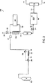
本発明は、これらの適用例のための二酸化炭素からのNVOR除去を認識し、それに対処する。本発明の一実施形態は、適用例に精製二酸化炭素を送達するための方法である。この方法は、系2の概略を例示する図1に関して説明する。系2は、精製される二酸化炭素を含有するタンク4を含む。好ましくは、タンク4は、約100−500psig(約689.5−3447.4kPa)の液体二酸化炭素、より好ましくは約200−350psig(約1379−2413.2kPa)の液体二酸化炭素を含有する。一般に、液体二酸化炭素は、約10重量ppm以下のNVOR、好ましくは約5重量ppm以下のNVORを含有する。
The present invention recognizes and addresses NVOR removal from carbon dioxide for these applications. One embodiment of the present invention is a method for delivering purified carbon dioxide to an application. This method will be described with reference to FIG.
二酸化炭素をタンク4から引き出し、熱交換器6でサブクールし、その後、ストリーム8としてポンプ10に送る。キャビテーションを防ぐために、ストリーム8の二酸化炭素が熱交換器6によってサブクールされる程度は、ポンプ10の要件によって決まる。二酸化炭素のさらなるNVOR混入を防ぐために、ポンプ10は、好ましくはエラストマー製の接液部分を持たないダイヤフラム型である。ポンプ10を離れる二酸化炭素の圧力は、たとえば約800から約5000psia(約5516−34473kPa)の範囲であり得る。好ましくは、この範囲は、約900から約3000psia(約6205−20684kPa)、たとえば1000psig(約6895kPa)である。
Carbon dioxide is withdrawn from the
ポンプ10からの加圧二酸化炭素を、次いで、加熱器12で気化又は加熱する。加熱器12は、電気抵抗性加熱を用いることができる。二酸化炭素の圧力がその臨界圧(約7253kPa)を超える場合、加熱器12は、ポンプ10からの加圧二酸化炭素を単純に加熱し、気化しない。超臨界圧では、加熱器12は省略できる。
The pressurized carbon dioxide from the
二酸化炭素はストリーム14(蒸気又は超臨界相)として加熱器12を離れ、次いで、それを酸化剤ストリーム16と混合して、ストリーム18を形成する。酸化剤ストリーム16は、好ましくは、空気又は酸素富化空気などの、酸素又は酸素含有ガスである。もっとも好ましくは、酸化剤ストリーム16は酸素である。他の酸化剤、たとえば過酸化水素、オゾン、亜酸化窒素、二酸化塩素、及び/又は過マンガン酸カリウムなどの過マンガン酸塩も用いることができる。酸化剤ストリーム16は、水分などの他の反応剤を含有することができ、それらは後に、二酸化炭素ストリーム14中の高分子量汚染物の分解を促進するために用いられる。酸化剤ストリーム16の流量は、バルブ20、又は質量流量コントローラを用いて制御する。酸化剤ストリーム16の流量は、所望量の酸化が促進されるのに充分な酸化剤がストリーム18に存在するように選択することができる。二酸化炭素ストリーム14がすでにNVORを酸化するのに充分な酸素を含有する場合、酸化剤ストリーム16は省略できる。
The carbon dioxide leaves the
次いで、ストリーム18を、コアレッサ22に送る。コアレッサ22は、金属表面の脱落に起因する可能性のある固体微粒子、及び二酸化炭素に溶解したが、二酸化炭素が熱交換器6及び/又は加熱器12を通過したときに溶液から出現した重い汚染物を含む、エアロゾル汚染物を低減するために用いられる。コアレッサ22は、液滴の凝集のために大きな表面積を提示し、固体又は沈殿相の汚染物部分を約0.05重量ppm以下に低減することのできる、微細繊維マットを含有するカートリッジ型などの1つ又は複数の高性能コアレッシングフィルタを含むことができる。好ましくは、構成材料は、二酸化炭素のエラストマー材料への曝露が最小となる又は低減されるものである。二酸化炭素が臨界相又は超臨界相にある場合、コアレッサ22は省略できる。
The
次いで、二酸化炭素をストリーム24としてコアレッサ22から送る。ストリーム24は、二酸化炭素を復熱交換器26に向ける。復熱交換器26は、加熱器28に入る前に、ストリーム24の二酸化炭素を加温する。復熱交換器26は加熱器28と共に、触媒反応器32の操作温度が、所望量の汚染物が必ず酸化されるのに充分であることを確実にする。
The carbon dioxide is then sent from the
二酸化炭素はストリーム30として加熱器28を離れ、触媒反応器32に送られる。触媒反応器32に入る二酸化炭素は、気体、液体、臨界流体、超臨界流体、又は近臨界流体であることができる。本明細書では、「近臨界」流体は、臨界温度(Tc)未満であるが、約0.75の臨界温度に対する材料の実際温度の比である換算温度(Tr)を超える温度にある流体を指す。臨界点に近いことから、近臨界流体は、臨界点をはるかに下回るほとんどの液体とは対照的に、相当量の圧縮性を示す液体様状態である。一般に近臨界液体の溶媒特性は、通常はほとんどの超臨界流体ほどではないが、圧力に強く依存する。
The carbon dioxide leaves the
触媒反応器32は、低分子量を有する酸化生成物への混合物分子の酸化を増進する少なくとも1種の触媒を含有する。低分子量を有するNVRは、高分子量を有するNVRに比べて、二酸化炭素から沈殿する可能性が低いと考えられている。本明細書では、「酸化」は、完全酸化、部分酸化、又は別の方法で分子内結合を切断して、低分子量を有する生成物を生ずることを含む。たとえば、炭化水素の完全酸化は、二酸化炭素及び/又は水などの酸化生成物を生じることができ、炭化水素の部分酸化は、1つ又は複数のより小さな炭化水素、二酸化炭素、及び/又は水を含む酸化生成物を生じることができる。ハロカーボンの完全酸化は、二酸化炭素及び/又はハロゲン酸ガスを含む酸化生成物を生じることができ、同じハロカーボンの部分酸化は、1つ又は複数のより小さなハロカーボン、二酸化炭素、ハロゲン酸、及び/又は水を生じることができる。
The
触媒は、ペレット、モノリス、又は他の形状であることができる。触媒には、炭素−炭素、窒素−炭素、炭素−ハロゲン、及び炭素−酸素結合などの、有機化合物に見出される化学結合の酸化を触媒する貴金属及び非貴金属を含むことができる。適切な触媒の例には、白金、白金アルミナ、パラジウム、パラジウムアルミナ、イリジウム、鉄、ロジウム、ルテニウム、ニッケルなどが含まれる。好ましくは、触媒は、白金又はパラジウムを含有する。 The catalyst can be in the form of pellets, monoliths, or other shapes. Catalysts can include noble and non-noble metals that catalyze the oxidation of chemical bonds found in organic compounds, such as carbon-carbon, nitrogen-carbon, carbon-halogen, and carbon-oxygen bonds. Examples of suitable catalysts include platinum, platinum alumina, palladium, palladium alumina, iridium, iron, rhodium, ruthenium, nickel and the like. Preferably, the catalyst contains platinum or palladium.
触媒反応器32の操作温度は一般に、二酸化炭素の純度要件、流入するストリームの純度、用いる触媒の種類、及び他の考慮すべき事柄によって決まる。一般に、操作温度は、得られた精製二酸化炭素が適用例68に用いられるとき、製品70に析出する又は取り込まれる粒子の量が許容範囲にあるように、充分なNVORが酸化されるのに充分な温度である。これは必ずしも完全な炭化水素分解を必要としないので、この温度は、完全にVOCを酸化するのに要する温度より低い温度であり得る。いくつかの適用例の場合、粒子析出又は取り込みの量は、溶解汚染物の一部のみが酸化される場合に、許容範囲とされ得る。たとえば、低分子汚染物は溶液に長く残存し、製品に析出しない、又は製品に取り込まれないので、いくつかの適用例は、比較的高い分子量を有する汚染物がより低い分子量に酸化されることのみを必要とする可能性がある。好ましくは、操作温度は、メタンを酸化するために触媒に必要とされる温度より低い温度である。一般に、触媒反応器32は、約200から約550°F(約93〜288℃)の範囲、より好ましくは約350から約550°F(約177〜288℃)の範囲の温度で操作される。
The operating temperature of the
一実施形態において、二酸化炭素中のNVORを酸化して、所与の適用例の許容量を超えないNVORレベルを有する精製二酸化炭素を生じるのに充分な温度を実質的に超えない温度で、二酸化炭素は触媒に曝露される。本明細書では、NVORを酸化するのに充分な温度を「実質的に超える」温度とは、同じ触媒を用いて二酸化炭素中の本質的にすべてのメタンが酸化される温度である。二酸化炭素中の「許容される」NVORレベルは、許容される品質を有する製品が生産されるように、その二酸化炭素が適用例において用いられることを可能にするレベルである。 In one embodiment, at a temperature that does not substantially exceed a temperature sufficient to oxidize NVOR in carbon dioxide to yield purified carbon dioxide having an NVOR level that does not exceed the tolerance of a given application. Carbon is exposed to the catalyst. As used herein, “substantially above” a temperature sufficient to oxidize NVOR is the temperature at which essentially all methane in carbon dioxide is oxidized using the same catalyst. An “acceptable” NVOR level in carbon dioxide is a level that allows the carbon dioxide to be used in an application such that a product with acceptable quality is produced.
触媒反応器32における二酸化炭素の空間速度は一般に、用いられる触媒材料、触媒の形態、操作温度、及び他の考慮すべき事柄によって決まる。350°F(約177℃)で操作される白金アルミナモノリス触媒の場合、空間速度は、好ましくは約500000scfh/ft3(触媒1立方メートル当たり1時間当たり500000標準立法メートル)未満、より好ましくは約200000scfh/ft3(触媒1立方メートル当たり1時間当たり200000標準立法メートル)未満である。
The space velocity of carbon dioxide in the
精製された二酸化炭素は、ストリーム34として触媒反応器32を出る。分析器36は、熱電対などの温度測定装置を用いてストリーム34の温度を測定する。分析器36が既定値と異なる温度を測定する場合、分析器36は加熱器28をオン又はオフにすることができる。このような方法で、分析器36は、触媒反応器32内部の温度が所望量の酸化を促進するのに充分であるように、ストリーム30が適切な温度であることを確実にする。
Purified carbon dioxide exits
次いで、ストリーム34は復熱交換器26に送られ、ここで冷却される。復熱交換器26において、ストリーム24及びストリーム34は、向流、並流、パイプインパイプ、又はクロスフロー配置であることができ、好ましくは向流配置である。精製二酸化炭素は、ストリーム38として復熱交換器26を離れる。
The
好ましい実施形態において、ポンプ10は、圧力分析器40によって作動され、圧力分析器40は、復熱交換器26を出るストリーム38の圧力を測定する。圧力分析器40は、既定値未満の圧力を測定したとき、ポンプ10を作動する。
In the preferred embodiment, the
さらなる精製を行うことなく、二酸化炭素ストリーム38のNVOR量は、標準立法フィート(0.028m 3 )当たり約1000沈殿粒子(標準立法メートル当たり約35000粒子)であることができ、粒子は標準温度及び標準圧力(NTP)で測定したとき、0.1ミクロン(0.1μm)超の直径を有する。より高い純度が所望である場合、NVRを含む他の汚染物を除去するために、ストリーム38を追加の精製ユニットに通すことができる。追加の精製ユニットは、凝集、吸着、吸収/蒸留、蒸留、化学吸着、化学反応(たとえば他の触媒反応器)、及び/又は乾燥スクラビングなどの技法を用いることができる。これらの技法は、好ましくは、触媒反応器内で有効に除去されない分子を除去することを目的とする。一実施形態において、ストリーム38は、酸化反応中に形成された水分を除去するために、1つ又は複数の手段に向けられる。
Without further purification, the NVOR amount of the
二酸化炭素ストリーム38の温度は、復熱交換器26の大きさ及び/又は流れの配置を変更することによって操作できる。或いは、復熱交換器26の下流に冷却器又は加熱器を設置することもできる。追加の精製手段が用いられる場合、二酸化炭素ストリーム38の温度を調節して、そのような手段の分離性能を最適化することができる。
The temperature of the
一例において、ストリーム38は精製床42に送られ、精製床42は吸着によって、燃焼生成物及び/又は他のNVRなどの汚染物を除去する。精製床42は、分子ふるい、シリカゲル、活性炭、又は他の適切な吸着剤などの吸着材料を用いることができる。平均的な精製床は、約40%のボイド率を有する。汚染物粒子が約0.1から約0.6ミクロン(約0.1から約0.6μm)の範囲の粒径である場合、吸着剤粒子に影響を与えることなく精製床を通ることができる。約0.1ミクロン(0.1μm)より小さい蒸気相汚染物分子及び小滴は、よりブラウン運動性の動きを示し、吸着剤と接触する可能性が高い。
In one example,
二酸化炭素はストリーム44として精製床42を離れる。次いで、ストリーム44は、固体粒子を除去するためにフィルタ46に送られる。この目的のためのフィルタは、蒸気相二酸化炭素から直径約0.003ミクロン(0.003μm)超の粒子を除去し、臨界及び超臨界二酸化炭素から直径約0.1ミクロン(0.1μm)超の粒子を除去する。好ましくは、フィルタ46は、全金属、焼結金属、エレクトロニクス等級フィルタである。
The carbon dioxide leaves the
二酸化炭素はストリーム48としてフィルタ46を離れ、コンデンサ50に送られる。コンデンサ50は、冷却ストリーム52を用いてストリーム48から熱を除去することにより、二酸化炭素ガスを凝縮して液体を生成し、冷却ストリーム52も同様に冷蔵器54によって冷却される。酸化剤ストリーム16によって導入される可能性のある軽い不純物(たとえば窒素、アルゴン、水素、及びヘリウム)は、コンデンサ50の凝縮を妨げる可能性がある。これらの軽い不純物は、バルブ58によって制御される排出ストリーム56を通して除去することができる。
The carbon dioxide leaves the
他の実施形態において、冷却ストリームは、たとえば冷却水のような当分野で知られている他の手段によって提供することができる。たとえば、二酸化炭素操作圧力は、約1000psig(約6895kPa)であり、二酸化炭素の凝縮温度は約81°F(約27.2℃)であるので、一般に冷却水は充分に冷たい。ストリーム48が臨界又は超臨界相にある場合、凝縮することなく、好都合な任意の貯蔵温度に冷却又は加熱することができる。
In other embodiments, the cooling stream can be provided by other means known in the art, such as cooling water. For example, the operating pressure of carbon dioxide is about 1000 psig (about 6895 kPa) and the condensation temperature of carbon dioxide is about 81 ° F. (about 27.2 ° C.), so the cooling water is generally cold enough. When
液体二酸化炭素はストリーム60としてコンデンサ50を出て、タンク62に進む。タンク62は、必要に応じて引き出すことのできる精製二酸化炭素の供給を保持する。タンク62は、連続又はバッチ様式で精製二酸化炭素を供給するのに充分な大きさであることができる。
Liquid carbon dioxide exits
コンデンサ50は、タンク62に対して高い位置に配置することもできる。このような方法では、引き出し量の少ない期間に、凝縮表面が覆われるまで、コンデンサ50及びタンク62に液体が蓄積する。これは凝縮プロセスを効果的に停止する。液体がタンク62から引き出されるとき、凝縮領域が曝露され、二酸化炭素蒸気が再び凝縮し、回路の圧力を低減し、ポンプ10を作動してタンク4からさらなる二酸化炭素を引き出し、それによって送達系を制御する。この配置は、引き出しがバッチ式の方法で行われる場合の条件に特によく適している。ストリーム48が臨界又は超臨界相である場合、「コンデンサ」内部の流体は、液体ではなく濃厚相流体である。
The
バルブ64は、タンク62からストリーム66として引き出される精製二酸化炭素の流量を制御し、その後、ストリーム66は適用例68に向けられる。酸化反応及び他の任意の分離方法が用いられた後、ストリーム66は、好ましくは、二酸化炭素標準立法フィート(0.028m 3 )当たり約100000以下の粒子(標準立法メートル当たり約3500000粒子)を有する二酸化炭素を含有し、粒子はNTPで測定したとき、0.1ミクロン(0.1μm)超の直径を有する。より好ましくは、二酸化炭素は、約10000以下の粒子(標準立法メートル当たり約350000粒子)を含有する。もっとも好ましくは、二酸化炭素は、約1000以下の粒子(標準立法メートル当たり約35000粒子)を含有する。ストリーム66中の二酸化炭素は、気体、臨界ガス、超臨界ガス、液体、又は固体、及び蒸気相(スノー洗浄適用例に用いられる場合など)などの、その適用例に必要とされる状態であることができる。任意選択で、二酸化炭素は、適用例68に送達する前に、たとえば溶媒のような1つ又は複数の成分と合わせることができる。
適用例68は製品70を調製するが、精製二酸化炭素を必要とする任意のプロセスであることができる。たとえば、適用例68は、フォトレジストストリッピング及び析出などのエレクトロニクス適用例、ナノ粒子形成などの薬剤適用例、MEMSの処理、又はスノー洗浄適用例であることができる。適用例68はウェハ洗浄ツールであることができ、製品70はウェハであることができる。
適用例68に用いられる二酸化炭素の純度は、許容される品質を有する製品が得られるように選択される。許容される品質は、所与の適用例の種類及び目的によって異なる。たとえば、許容される品質は、あるレベルの純度であることができ、たとえば最終薬剤材料があるレベル未満の汚染物濃度を有さなければならない場合に薬剤適用例において必要とされるレベルなどである。製品70がウェハである場合、許容される品質は、最大値以下の析出汚染物粒子数であることができる。
The purity of the carbon dioxide used in application example 68 is selected so as to obtain a product with acceptable quality. The acceptable quality depends on the type and purpose of a given application. For example, acceptable quality can be a certain level of purity, such as the level required in drug applications when the final drug material must have a contaminant concentration below a certain level, etc. . If the
製品70が許容される品質を有するかどうかを判定する方法は、所与の適用例によって異なる。その製品をモニターして、適用例に向けて送られる二酸化炭素中のNVORの許容レベルを求めることができる。半導体適用例の場合、たとえば、製品の品質は、当分野で知られている光散乱法によって求めることができる。いくつかの光散乱法は、固体表面において約0.1ミクロン(0.1μm)超の有効な直径を有する粒子を測定することができる。適切な方法は、Diaz、R.E.等の「汚染物を含まない半導体及び他の精密製品の製造におけるオンウェハ粒子測定(On-Wafer Measurement of Particles in Contamination-Free Manufacturing for Semiconductors and other Precision Products)」、汚染物を含まない半導体及び他の精密製品の製造(Contamination-Free Manufacturing for Semiconductors and other Precision Products)、R.P.Donovan編(Marcell Dekker)、79頁(2001)に記載されている。薬剤適用例では、製品(たとえば粉末)を評価して、製品上又は製品中に許容レベル以下のNVORが捕捉されているかどうかを判定することができる。他の場合には、所与の適用例に関するNVORの許容レベルは、既存のデータ、チャート、又は業界標準に基づいて求めることができる。
The method for determining whether
任意選択で、適用例68に入る、又は適用例68を離れる二酸化炭素の純度をモニターすることができる。このモニタリングは、適用例68に用いられる(又は用いられた)二酸化炭素が許容される品質を有する加工中製品又は製品をもたらすかどうかを判定するために有用である可能性がある。たとえば図1において、送達された二酸化炭素の純度は、分析器80で測定される。この配置では、精製二酸化炭素の少なくとも一部を引き出し、加熱器84で加温した粒子フィルタ82に通し、減圧装置86を通して圧力を低減して、その圧力で二酸化炭素の昇華温度より高く、より好ましくは周囲温度に近い低圧ガスストリームを得る。分析器80の測定値に基づいて、確実に純度規格を満たすように、酸化ストリーム16の流量及び/又は触媒反応器32の操作温度を変更することができる。好ましくは、規格は、標準温度及び標準圧力において1立法フィート(0.028m 3 )当たり約100000以下の粒子(1立法メートル当たり約3500000粒子)であり、粒子は0.1ミクロン(0.1μm)超の直径を有する。より好ましくは、規格は、約10000以下の粒子(1立法メートル当たり約350000粒子)である。もっとも好ましくは、規格は、約1000以下の粒子(1立法メートル当たり約35000粒子)である。
Optionally, the purity of carbon dioxide entering or leaving
分析器80は、様々な種類の分析器であることができる。好ましくは、分析器80は、整理番号3011.1006−001(D−21187)であり、「二酸化炭素中の不純物を分析する方法(Method for Analyzing Impurities in Carbon Dioxide)」という名称の2003年1月22日に出願された米国特許出願第10/350307号に記載されている分析器などの、光散乱技法又は単一粒子計数器に基づく粒子分析器である。この出願の教示は、その全体を参照により本明細書の一部とする。二酸化炭素が許容される結果をもたらすかどうかを判定するために、汚染物の少なくとも一部が沈殿形態であるように二酸化炭素の状態を変更する。次いで、光散乱粒子計数器又は単一粒子計数器などの粒子検出器に汚染物を通す。一般に、光散乱粒子計数器は、粒子の光ビームとの相互作用によって粒子を検出する。単一粒子計数器は、単一粒子の相互作用を検出するのに充分な感度を有する。
The
許容される品質を有する製品を生じるストリームの純度がひとたび決定されたら、精製二酸化炭素ストリームが確実に適用例68の許容NVORレベルを有するように、触媒反応器32の温度を制御することができる。
Once the purity of the stream that yields a product with acceptable quality is determined, the temperature of the
製品70が充分に処理されたとき、二酸化炭素、及び取り込まれ且つ/又は溶解した任意の汚染物は、排出ストリーム72によって適用例68を離れる。所望であれば、排出ストリーム72を相分離器74に送り、ストリーム72に含有される任意の蒸気、液体、及び固体を分離することができる。液体及び/又は固体は、ストリーム76として相分離器74を出るが、ストリーム76は、廃棄又は再生のために回収することができる。蒸気はストリーム78として分離器74を離れ、さらなる使用のために通気又は再循環することができる。
When the
好ましくは、系2の構成に用いられる材料は、二酸化炭素に汚染物を浸出する可能性のあるエラストマー材料への二酸化炭素の曝露を最小限に抑えるように選択される。UHP構築技法(たとえば電解研磨表面の使用、円周溶接)も特に触媒反応器32の下流で好ましい。
Preferably, the materials used in the construction of
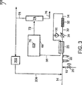
図2は、系100を示す。系100内でポンプは用いない。系100の二酸化炭素の圧力は、実質的にタンク4の圧力と同じである。タンク4の液体又は蒸気二酸化炭素を、二酸化炭素のほぼ蒸気圧で引き出す。たとえば、タンク4が室温(約21.1℃)である場合、二酸化炭素蒸気は、ほぼ飽和圧力(約5861kPa)となる。タンク4内部で必要な圧力を維持するために、熱源102は小量の熱をタンク4の二酸化炭素に加えることができる。
FIG. 2 shows the
使用率に応じて、単一シリンダ、又は分岐したシリンダ列を用いることができる。系100において、系2(図1)に示したコアレッサ22及び復熱交換器26は省略される。加熱器28は、タンク4を離れる二酸化炭素の温度を、触媒反応器32の内部で必要とされる温度に上昇させる。さらに、精製床42(図1)は省略され、コンデンサ50(図1)は熱交換器104に置き換えられた。バルブ58を開けることによって、ライン56は、熱交換器104から軽い不純物を通気できる。
Depending on the usage rate, a single cylinder or a branched cylinder row can be used. In the
系100は、少ない流量の精製二酸化炭素を必要とする適用例、又は一連のシリンダから送達された二酸化炭素を用いる適用例に特に適している。
図3は、適用例68での使用後に、二酸化炭素の少なくとも一部が再利用される系200を例示する。ストリーム78の二酸化炭素の少なくとも一部が再利用される。所望であれば、再利用部分は、任意の精製手段202に送ることができ、精製手段202は、ハロゲン化合物などの、触媒反応器32において触媒を汚染する可能性のある汚染物を除去することができる。任意の精製手段202には、吸着、化学吸着、化学反応、相分離、吸収、蒸留、濾過、並びに当分野で知られている他の分離技法を含むことができる。次いで、本質的に上述のとおり、ストリーム204の再利用二酸化炭素をストリーム14及び酸化剤ストリーム16と混合し、その後、触媒反応器32に送る。
FIG. 3 illustrates a
図4は、触媒反応器32がタンク4の供給圧以下の圧力で操作される系300を例示する。流量制御装置302は、タンク4からの二酸化炭素の流量を制御する。流量制御装置302は、たとえばフローオリフィス、又は流量制御バルブであることができる。ストリーム60のサブクール液体二酸化炭素を、ポンプ304によってタンク62に送る。差圧分析器306は、タンク62の静水頭に基づいてポンプ304を作動することができる。或いは、ポンプ304は、タンク62の重量に基づいて作動される。
FIG. 4 illustrates a
図1に例示した系2に類似の系で、二酸化炭素を精製した。SFE等級の二酸化炭素を含有する二酸化炭素シリンダの蒸気空間から二酸化炭素を引き出した。このシリンダは、周囲温度及び約820psia(約5654kPa)の圧力で飽和液体を含有した。次いでその蒸気を、シリンダ圧で機能するコアレッシングフィルタに通した。このストリームを減圧し、固体粒子を除去するために、0.003ミクロン(0.003μm)エレクトロニクス等級粒子フィルタに通した。下流の粒子分析器に入る二酸化炭素がほぼ周囲温度であることを確実にするために、減圧装置の上流に熱を加えた。図5は、ストリームの低減した圧力の関数として粒子数を示す。もっとも高い圧力において、圧力の低減は小さく、粒子数の低減も小さい。このことは高性能のコアレッサの使用と矛盾しない。しかしながら、圧力がさらに低減されると、多数のサブミクロンの小滴が形成される。これは、二酸化炭素中の重い汚染物の溶解性が、圧力の低減につれて実際に低下することを示唆している。減圧手段から脱落する固体粒子は、測定されたレベルと比較してごくわずかであることが示され、粒子の圧倒的多数は二酸化炭素中の汚染物の溶解性の低下によって生じたものであるという事実が支持された。
Carbon dioxide was purified in a system similar to
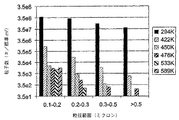
300psig(約2068kPa)のEIG二酸化炭素液体をバルクタンクから引き出し、蒸発させ、熱触媒反応器に通した。この触媒反応器は、Sud−Chemie Prototech Inc.(Needham、MA)の3種のPRO*VOC10触媒を含んだ。PRO*VOC10触媒は、セラミックフォーム上の白金ベース金属である。反応器を周囲温度(約21.1℃)から315.6℃まで種々の温度で操作した。すべての試験において、空間速度は44000scfh/ft3(触媒量1立方メートル当たり1時間当たり44000標準立法メートル)であった。反応器の上流で二酸化炭素に酸素を添加し、混合物中に600体積ppmの酸素を得た。 300 psig (about 2068 kPa) of EIG carbon dioxide liquid was withdrawn from the bulk tank, evaporated and passed through a thermal catalytic reactor. This catalytic reactor is manufactured by Sud-Chemie Prototech Inc. Three PRO * VOC10 catalysts (Needham, MA) were included. PRO * VOC10 catalyst is a platinum-based metal on ceramic foam. The reactor was operated at various temperatures from ambient temperature (about 21.1 ° C.) to 315.6 ° C. In all tests, the space velocity was 44000 scfh / ft 3 (44,000 standard cubic meters per hour per cubic meter of catalyst). Oxygen was added to the carbon dioxide upstream of the reactor to obtain 600 volume ppm oxygen in the mixture.
図6は反応温度の関数として粒度分布を示すが、これらの粒子は、周囲温度及び反応器とほぼ同じ圧力で、反応器の下流で測定した。反応器が本質的に室温であったとき、測定された粒子数は非常に多い。しかしながら、触媒が300°F(約148.9℃)以上で操作されたとき、測定された粒子数は劇的に減少した。350°F(約176.6℃)を超える温度での操作は、非常に低いNVORレベルを生じた。 FIG. 6 shows the particle size distribution as a function of reaction temperature, but these particles were measured downstream of the reactor at ambient temperature and approximately the same pressure as the reactor. When the reactor was essentially at room temperature, the number of particles measured was very high. However, when the catalyst was operated above 300 ° F. (about 148.9 ° C.), the number of particles measured decreased dramatically. Operation at temperatures above 350 ° F. (about 176.6 ° C.) resulted in very low NVOR levels.
反応器の下流で固体粒子フィルタを用いなかったことに留意されたい。したがって、測定された粒子レベルは固体粒子、たとえば触媒によって脱落した可能性のある固体粒子などを含む。 Note that no solid particle filter was used downstream of the reactor. Thus, the measured particle level includes solid particles, such as solid particles that may have fallen off by the catalyst.
反応器温度の関数のエアロゾル総濃度として、同じデータを図7に示す。エアロゾル濃度を算出するために、いくつかの仮説を立てた。第1に、典型的な粒子は、所与の各範囲において最小であると考えられる。たとえば、0.2〜0.3ミクロン(0.2〜0.3μm)の粒径範囲において、その粒径は0.2ミクロン(0.2μm)であると考えられる。第2に、混合物粒子の比重は0.8であると推定した。 The same data is shown in FIG. 7 as the total aerosol concentration as a function of reactor temperature. Several hypotheses were made to calculate the aerosol concentration. First, typical particles are considered to be minimal in each given range. For example, in the particle size range of 0.2 to 0.3 microns (0.2 to 0.3 μm ), the particle size is considered to be 0.2 microns (0.2 μm) . Second, the specific gravity of the mixture particles was estimated to be 0.8.
図7は、反応温度とNVOR除去との間には強い相関があり、温度と共にエアロゾル濃度が劇的に低減することを実証する。このデータは、触媒及び/又は分配管から生じた固体粒子の寄与のために測定されたエアロゾル濃度が低いとき、NVOR除去に対する温度の影響をマスクしている可能性がある。 FIG. 7 demonstrates a strong correlation between reaction temperature and NVOR removal, demonstrating that the aerosol concentration decreases dramatically with temperature. This data may mask the effect of temperature on NVOR removal when the measured aerosol concentration is low due to solid particle contributions from the catalyst and / or distribution pipe.
反応器の前に凝集は行わず、実施例2に記載のとおり3種のPRO*VOC10触媒(セラミックフォーム上のPtベース金属)を含有する触媒反応器に、再びEIG二酸化炭素を通した。反応器の温度は600°F(315.5℃)であり、過剰酸素(約600体積ppm)をストリームに添加した。これらの条件下で、反応器圧及び周囲温度における粒子計数は、粒子の本質的に完全な消滅を示した。 There was no agglomeration prior to the reactor, and EIG carbon dioxide was again passed through the catalytic reactor containing the three PRO * VOC10 catalysts (Pt base metal on ceramic foam) as described in Example 2. The reactor temperature was 600 ° F. (315.5 ° C.) and excess oxygen (about 600 ppm by volume) was added to the stream. Under these conditions, particle counts at reactor pressure and ambient temperature showed essentially complete disappearance of the particles.
図8は、周囲温度及び圧力近くで操作される低圧粒子分析器のストリームの2つの空間速度における同時分析を示す。触媒系に供給された蒸気の粒子数は、標準温度及び圧力で測定したとき、1立方フィート当たり107超(1立方メートル当たり約353×106粒子)である。反応器の下流では、空間速度140000及び70000scfh/ft3(それぞれ触媒量1立方メートル当たり1時間当たり140000及び70000標準立法メートル)において、粒子数はNTPで測定したとき、それぞれ1立方フィート当たり約600及び100粒子(それぞれ1立方メートル当たり21000及び3500粒子)に低減される。 FIG. 8 shows a simultaneous analysis at two space velocities of a low pressure particle analyzer stream operating near ambient temperature and pressure. The number of vapor particles fed to the catalyst system is greater than 10 7 per cubic foot (approximately 353 × 10 6 particles per cubic meter) when measured at standard temperature and pressure. Downstream of the reactor, at a space velocity of 140000 and 70000 scfh / ft 3 (14,000 and 70000 standard cubic meters per hour per 1 meter of catalyst amount, respectively), the number of particles when measured by NTP is about 600 and 1 per cubic foot, respectively. Reduced to 100 particles (21000 and 3500 particles per cubic meter, respectively).
実施例2に記載のとおり、3種のPRO*VOC10触媒(セラミックフォーム上のPtベース金属)を含有する触媒反応器に、EIG二酸化炭素を通した。バルクタンク源から供給される二酸化炭素に、追加の酸素は添加しなかった。反応器は、約700°F(約371℃)及び空間速度約140000scfh/ft3(触媒1立方メートル当たり1時間当たり約140000標準立法メートル)で操作した。パラジウム触媒で被覆された金属モノリスを反応器内で用いた。周囲温度及び圧力で粒子分析を行った。この場合も、系に供給される二酸化炭素は、NTPにおいて1立方フィート当たり107超の粒子(1立方メートル当たり約353×106粒子)を有する。 As described in Example 2, EIG carbon dioxide was passed through a catalytic reactor containing three PRO * VOC10 catalysts (Pt base metal on ceramic foam). No additional oxygen was added to the carbon dioxide supplied from the bulk tank source. The reactor was operated at about 700 ° F. (about 371 ° C.) and a space velocity of about 140000 scfh / ft 3 (about 140000 standard cubic meters per hour per cubic meter of catalyst). A metal monolith coated with a palladium catalyst was used in the reactor. Particle analysis was performed at ambient temperature and pressure. Again, the carbon dioxide fed to the system has more than 10 7 particles per cubic foot in NTP (approximately 353 × 10 6 particles per cubic meter).
図9は、NTPで測定された、反応器を離れる粒子の粒度分布を示す。反応器を離れる二酸化炭素は、1立方フィート当たり50未満の粒子(1立方メートル当たり約1765粒子)を有する。粒子数の減少(ほぼNTPで測定した、系を離れる粒子に対する系に入る粒子の比)は約6桁である。汚染物の少ないストリームでは、粒度分布は粒度の小さい粒子にシフトするので、汚染物の重量に関する相対的低減はさらに大きい。この場合、追加の反応剤を二酸化炭素と混合する、又は反応器の上流で凝集を行う必要なしに、優れた性能が得られた。これは、反応剤の二酸化炭素との混合は、良好な精製を達成するために必要でない可能性のあることを示した。追加反応剤の必要性は、重い汚染物のレベル、並びに流入する二酸化炭素に存在する酸素及び水分の量に依存する。 FIG. 9 shows the particle size distribution of the particles leaving the reactor as measured by NTP. The carbon dioxide leaving the reactor has less than 50 particles per cubic foot (about 1765 particles per cubic meter). The reduction in the number of particles (ratio of particles entering the system to particles leaving the system, measured approximately at NTP) is about 6 orders of magnitude. For streams with fewer contaminants, the particle size distribution shifts to smaller particles, so the relative reduction in contaminant weight is even greater. In this case, excellent performance was obtained without the need to mix additional reactants with carbon dioxide or to perform agglomeration upstream of the reactor. This indicated that mixing of the reactants with carbon dioxide may not be necessary to achieve good purification. The need for additional reactants depends on the level of heavy contaminants and the amount of oxygen and moisture present in the incoming carbon dioxide.
本発明を特にその好ましい実施形態に関して示し、説明したが、添付の請求の範囲によって包含される本発明の範囲から逸脱することなく、形態及び詳細に様々な変更を加えられることを当分野の技術者は理解するであろう。 While the invention has been particularly shown and described with reference to preferred embodiments thereof, it is understood that various changes in form and detail may be made without departing from the scope of the invention as encompassed by the appended claims. Will understand.
Claims (25)
a)適用例における前記精製二酸化炭素の使用が、許容される製品をもたらすように、精製二酸化炭素中の不揮発性有機残留物の許容レベルを求めるステップ、
b)前記精製二酸化炭素を生成するように制御された温度で、二酸化炭素を少なくとも1種の触媒に曝露するステップであって、前記精製二酸化炭素を生成するように制御された温度は93〜288℃であり、前記精製二酸化炭素が、10ppb未満の不揮発性有機残留物濃度を有するステップ、及び
c)前記精製二酸化炭素を前記適用例に送るステップを含み、
しかも、前記二酸化炭素を前記触媒に曝露する前に、前記二酸化炭素に水を添加することを含み、
前記適用例が、半導体処理である方法。A method for delivering purified carbon dioxide to an application comprising:
a) determining an acceptable level of non-volatile organic residues in the purified carbon dioxide such that use of the purified carbon dioxide in the application results in an acceptable product;
b) exposing carbon dioxide to at least one catalyst at a temperature controlled to produce the purified carbon dioxide , wherein the temperature controlled to produce the purified carbon dioxide is 93-288. And wherein the purified carbon dioxide has a non-volatile organic residue concentration of less than 10 ppb, and c) sending the purified carbon dioxide to the application.
And adding water to the carbon dioxide prior to exposing the carbon dioxide to the catalyst,
A method in which the application example is semiconductor processing.
a)二酸化炭素を少なくとも1種の触媒に曝露するステップであって、前記二酸化炭素が、臨界、及び超臨界からなる群から選択された状態であるステップ、及び
b)汚染物の少なくとも一部を酸化し、それによって精製二酸化炭素を形成するステップを含み、
しかも、前記二酸化炭素を前記触媒に曝露する前に、前記二酸化炭素に水を添加することを含む、方法。A method for purifying carbon dioxide, comprising:
a) exposing carbon dioxide to at least one catalyst, wherein the carbon dioxide is selected from the group consisting of critical and supercritical; and b) at least some of the contaminants. Oxidizing, thereby forming purified carbon dioxide,
Moreover, the method comprises adding water to the carbon dioxide before exposing the carbon dioxide to the catalyst.
Applications Claiming Priority (2)
| Application Number | Priority Date | Filing Date | Title |
|---|---|---|---|
| US35806502P | 2002-02-19 | 2002-02-19 | |
| PCT/US2003/005174 WO2003070635A1 (en) | 2002-02-19 | 2003-02-19 | Method for removing contaminants from gases |
Publications (3)
| Publication Number | Publication Date |
|---|---|
| JP2005517623A JP2005517623A (en) | 2005-06-16 |
| JP2005517623A5 JP2005517623A5 (en) | 2005-12-22 |
| JP4680511B2 true JP4680511B2 (en) | 2011-05-11 |
Family
ID=27757695
Family Applications (1)
| Application Number | Title | Priority Date | Filing Date |
|---|---|---|---|
| JP2003569553A Expired - Fee Related JP4680511B2 (en) | 2002-02-19 | 2003-02-19 | How to remove contaminants from gases |
Country Status (8)
| Country | Link |
|---|---|
| US (1) | US6962629B2 (en) |
| EP (1) | EP1476396A4 (en) |
| JP (1) | JP4680511B2 (en) |
| KR (2) | KR101284395B1 (en) |
| CN (1) | CN100519413C (en) |
| AU (1) | AU2003217616A1 (en) |
| TW (1) | TWI263537B (en) |
| WO (1) | WO2003070635A1 (en) |
Families Citing this family (42)
| Publication number | Priority date | Publication date | Assignee | Title |
|---|---|---|---|---|
| CN1331562C (en) * | 2001-10-17 | 2007-08-15 | 普莱克斯技术有限公司 | Central carbon dioxide purifier |
| WO2004035178A1 (en) * | 2002-10-17 | 2004-04-29 | Mykrolis Corporation | Method for purifying carbon dioxide |
| US20070113739A1 (en) * | 2003-05-13 | 2007-05-24 | Domnick Hunter Limited | Filter assembly for treating a compressed gas |
| US20050211090A1 (en) * | 2003-08-25 | 2005-09-29 | Mccullough Matthew L | Method for achieving ultra-low emission limits in VOC control |
| US20060048778A1 (en) * | 2004-09-07 | 2006-03-09 | Honeywell International, Inc. | Low pressure-drop respirator filter |
| US20070028766A1 (en) * | 2005-08-08 | 2007-02-08 | Ravi Jain | Method for removing impurities from a gas |
| US7481985B2 (en) * | 2005-08-08 | 2009-01-27 | The Boc Group, Inc. | Method of removing impurities from a gas |
| US8017405B2 (en) | 2005-08-08 | 2011-09-13 | The Boc Group, Inc. | Gas analysis method |
| US20070028764A1 (en) * | 2005-08-08 | 2007-02-08 | Carsten Wittrup | Method for enabling the provision of purified carbon dioxide |
| US20070031302A1 (en) * | 2005-08-08 | 2007-02-08 | Carsten Wittrup | Method and apparatus for purifying a gas |
| US7556671B2 (en) | 2005-08-08 | 2009-07-07 | The Boc Group, Inc. | System and method for purifying a gas |
| KR100753493B1 (en) * | 2006-01-21 | 2007-08-31 | 서강대학교산학협력단 | Cleaning apparatus |
| JP5194259B2 (en) * | 2006-07-07 | 2013-05-08 | ティーイーエル エフエスアイ,インコーポレイティド | Liquid aerosol particle removal method |
| CA2696975A1 (en) * | 2006-08-18 | 2008-02-21 | Semo Milling, Llc | Power production using grain fractionation products |
| US8961881B2 (en) * | 2007-04-17 | 2015-02-24 | Honeywell International Inc. | Multi-stage catalytic air purification system |
| JP4973937B2 (en) * | 2007-08-24 | 2012-07-11 | オルガノ株式会社 | Fine particle measurement system and fine particle measurement method in high pressure fluid |
| TWI335971B (en) * | 2007-11-02 | 2011-01-11 | Metal Ind Res & Dev Ct | Co2 source providing device |
| JP5147002B2 (en) * | 2008-02-13 | 2013-02-20 | オルガノ株式会社 | High pressure carbon dioxide filtration method and filtration apparatus |
| US20100290977A1 (en) * | 2009-05-15 | 2010-11-18 | Bowers Charles W | Method of removing hydrocarbon impurities from a gas |
| US8667817B2 (en) * | 2009-06-11 | 2014-03-11 | Guardian Ignition Interlock Manufacturing, Inc. | Ozone laundry system and its method of use with continuous batch and tunnel washers |
| WO2011089382A2 (en) * | 2010-01-21 | 2011-07-28 | Bp Alternative Energy International Limited | Purification of a co2-rich stream |
| US8486361B2 (en) | 2010-03-11 | 2013-07-16 | Alstom Technology Ltd | System and method for generating a carbon dioxide stream |
| US20130037054A1 (en) * | 2010-04-28 | 2013-02-14 | Nobuhiro Saruya | Method for producing imaging lens |
| WO2012055695A1 (en) * | 2010-10-26 | 2012-05-03 | Shell Internationale Research Maatschappij B.V. | Process for the separation of contaminant or mixture of contaminants from a ch4-comprising gaseous feed stream |
| US20140080115A1 (en) * | 2011-02-14 | 2014-03-20 | The Administrators Of The Tulane Educational Fund | Device and method for monitoring the presence, onset and evolution of particulates in chemically or physically reacting systems |
| JP2013032245A (en) * | 2011-08-02 | 2013-02-14 | Japan Organo Co Ltd | Method and system for purifying and supplying carbon dioxide |
| CN104380438B (en) | 2012-04-17 | 2018-11-06 | 普莱克斯技术有限公司 | The system for being delivered to handling implement for multiphase carbon dioxide will to be purified |
| US11466237B2 (en) | 2013-04-18 | 2022-10-11 | Aromaloc Inc. | Apparatus and method for preserving the aroma of a fermentable beverage |
| EP2986700B1 (en) * | 2013-04-18 | 2019-04-03 | Aromaloc Inc. | Method for preserving the aroma of a fermentable beverage |
| CN106103342B (en) * | 2014-03-14 | 2018-01-23 | 工程吸气公司 | System and method for ultra-high purity (UHP) carbon dioxide purification |
| TWI586425B (en) * | 2014-06-04 | 2017-06-11 | 中國鋼鐵股份有限公司 | Denitrification catalyst and method of producing the same |
| EP3031956B1 (en) | 2014-12-10 | 2017-07-26 | Haldor Topsoe As | A process for the preparation of ultra-high purity carbon monoxide |
| KR102189750B1 (en) * | 2016-06-03 | 2020-12-14 | 파티클 머슈어링 시스템즈, 인크. | System and method for separating condensate in condensate nucleus counter |
| KR102489730B1 (en) | 2016-07-29 | 2023-01-18 | 삼성전자주식회사 | Source supplier for supercritical fluid, substrate treating apparatus having the same and method of treating substrates in the substrate treating apparatus |
| US10428306B2 (en) | 2016-08-12 | 2019-10-01 | Warsaw Orthopedic, Inc. | Method and system for tissue treatment with critical/supercritical carbon dioxide |
| CN106979664B (en) * | 2017-03-06 | 2019-09-20 | 毛恒松 | Atmospheric carbon dioxide liquifying method |
| US20180323063A1 (en) * | 2017-05-03 | 2018-11-08 | Applied Materials, Inc. | Method and apparatus for using supercritical fluids in semiconductor applications |
| FR3070016B1 (en) * | 2017-08-10 | 2019-08-23 | L'air Liquide, Societe Anonyme Pour L'etude Et L'exploitation Des Procedes Georges Claude | METHOD AND APPARATUS FOR PURIFYING A GAS FLOW OF SUPPLY COMPRISING AT LEAST 90% CO2 |
| IL255268B (en) * | 2017-10-26 | 2019-01-31 | Izun Pharmaceuticals Corp | Smoke capturing system and method |
| US11358183B2 (en) * | 2017-12-20 | 2022-06-14 | Halliburton Energy Services, Inc. | Capture and recycling methods for non-aqueous cleaning materials |
| KR102214542B1 (en) * | 2020-06-22 | 2021-02-10 | 에이티티(주) | Measuring device for total organic carbon |
| TWI722956B (en) * | 2020-08-17 | 2021-03-21 | 傑明科技有限公司 | Pm2.5 control device designed by combining particle condensation growth and inertial impaction techniques |
Citations (9)
| Publication number | Priority date | Publication date | Assignee | Title |
|---|---|---|---|---|
| US2999008A (en) * | 1957-03-20 | 1961-09-05 | Vulcan Cincinnati Inc | Purification of carbon dioxide for urea synthesis |
| US3317278A (en) * | 1962-11-29 | 1967-05-02 | Petrocarbon Dev Ltd | Purification of carbon dioxide |
| US4344486A (en) * | 1981-02-27 | 1982-08-17 | Standard Oil Company (Indiana) | Method for enhanced oil recovery |
| US4460395A (en) * | 1983-01-18 | 1984-07-17 | The Pritchard Corporation | Method and apparatus for producing food grade carbon dioxide |
| US4521387A (en) * | 1982-11-23 | 1985-06-04 | Basf Aktiengesellschaft | Purification of gases containing CO and/or CO2 |
| EP0410845A1 (en) * | 1989-07-17 | 1991-01-30 | L'air Liquide, Societe Anonyme Pour L'etude Et L'exploitation Des Procedes Georges Claude | Recovery of carbon dioxide plant vent gas using membranes |
| EP0952111A1 (en) * | 1998-04-24 | 1999-10-27 | Praxair Technology, Inc. | CO2 purification system |
| US6224843B1 (en) * | 1999-09-13 | 2001-05-01 | Saudi Basic Industries Corporation | Carbon dioxide purification in ethylene glycol plants |
| JP2001261320A (en) * | 2000-03-21 | 2001-09-26 | Nippon Sanso Corp | Method and device for supplying purified liquefied carbon dioxide and method and device for cleaning with dry ice snow |
Family Cites Families (19)
| Publication number | Priority date | Publication date | Assignee | Title |
|---|---|---|---|---|
| JPS61127613A (en) * | 1984-11-22 | 1986-06-14 | Mitsui Toatsu Chem Inc | Purifying method of carbon dioxide |
| DE3575905D1 (en) * | 1984-11-22 | 1990-03-15 | Mitsui Toatsu Chemicals | METHOD FOR PURIFYING CARBON DIOXIDE. |
| GB8505689D0 (en) | 1985-03-05 | 1985-04-03 | Atkins & Partners W S | Liquefaction of carbon dioxide |
| US4759782A (en) | 1985-07-05 | 1988-07-26 | Pall Corporation | Coalescing filter for removal of liquid aerosols from gaseous streams |
| JPH0622224B2 (en) | 1988-03-05 | 1994-03-23 | 大阪酸素工業株式会社 | Supply of liquefied carbon dioxide with few or no particles |
| US5470154A (en) | 1991-04-18 | 1995-11-28 | Osaka Sanso Kogyo Ltd. | Method of cleaning the reflector mirror in an optical dew point meter and an optical dew point meter equipped with a cleaning device |
| DE4305386A1 (en) * | 1993-02-22 | 1994-08-25 | Leuna Werke Gmbh | Catalyst and process for cleaning carbon dioxide |
| US5612011A (en) | 1993-07-16 | 1997-03-18 | Sinco Engineering S.P.A. | Process for the purification of inert gases |
| US5738835A (en) | 1994-08-31 | 1998-04-14 | Zimmer Aktiengesellschaft | Process for the purification of process gases by catalytic oxidation |
| US5557030A (en) | 1995-03-23 | 1996-09-17 | Uop | Process for rejecting heavy hydrocarbons from light hydrocarbons gases |
| US5700310A (en) | 1995-12-29 | 1997-12-23 | Mg Generon, Inc. | Removal of oil from compressed gas with macroporous polymeric adsorbent |
| US5914091A (en) | 1996-02-15 | 1999-06-22 | Atmi Ecosys Corp. | Point-of-use catalytic oxidation apparatus and method for treatment of voc-containing gas streams |
| US5858068A (en) | 1997-10-09 | 1999-01-12 | Uop Llc | Purification of carbon dioxide |
| US6099619A (en) | 1997-10-09 | 2000-08-08 | Uop Llc | Purification of carbon dioxide |
| US6074459A (en) | 1998-01-05 | 2000-06-13 | Uop Llc | Ultra pure gases: removal of halocarbons, fluorocarbons, and sulfur compounds from gas streams |
| US6612317B2 (en) | 2000-04-18 | 2003-09-02 | S.C. Fluids, Inc | Supercritical fluid delivery and recovery system for semiconductor wafer processing |
| US6327872B1 (en) | 2000-01-05 | 2001-12-11 | The Boc Group, Inc. | Method and apparatus for producing a pressurized high purity liquid carbon dioxide stream |
| US6361696B1 (en) | 2000-01-19 | 2002-03-26 | Aeronex, Inc. | Self-regenerative process for contaminant removal from liquid and supercritical CO2 fluid streams |
| US6979362B2 (en) | 2001-04-24 | 2005-12-27 | Jackson David P | Apparatus and process for the treatment, delivery and recycle of process fluids used in dense phase carbon dioxide applications |
-
2003
- 2003-02-19 KR KR1020117025767A patent/KR101284395B1/en active IP Right Grant
- 2003-02-19 KR KR10-2004-7012793A patent/KR20040086395A/en not_active Application Discontinuation
- 2003-02-19 WO PCT/US2003/005174 patent/WO2003070635A1/en active Application Filing
- 2003-02-19 AU AU2003217616A patent/AU2003217616A1/en not_active Abandoned
- 2003-02-19 EP EP03713572A patent/EP1476396A4/en active Pending
- 2003-02-19 CN CNB038086840A patent/CN100519413C/en not_active Expired - Fee Related
- 2003-02-19 JP JP2003569553A patent/JP4680511B2/en not_active Expired - Fee Related
- 2003-02-19 US US10/370,045 patent/US6962629B2/en not_active Expired - Lifetime
- 2003-02-19 TW TW092103443A patent/TWI263537B/en not_active IP Right Cessation
Patent Citations (9)
| Publication number | Priority date | Publication date | Assignee | Title |
|---|---|---|---|---|
| US2999008A (en) * | 1957-03-20 | 1961-09-05 | Vulcan Cincinnati Inc | Purification of carbon dioxide for urea synthesis |
| US3317278A (en) * | 1962-11-29 | 1967-05-02 | Petrocarbon Dev Ltd | Purification of carbon dioxide |
| US4344486A (en) * | 1981-02-27 | 1982-08-17 | Standard Oil Company (Indiana) | Method for enhanced oil recovery |
| US4521387A (en) * | 1982-11-23 | 1985-06-04 | Basf Aktiengesellschaft | Purification of gases containing CO and/or CO2 |
| US4460395A (en) * | 1983-01-18 | 1984-07-17 | The Pritchard Corporation | Method and apparatus for producing food grade carbon dioxide |
| EP0410845A1 (en) * | 1989-07-17 | 1991-01-30 | L'air Liquide, Societe Anonyme Pour L'etude Et L'exploitation Des Procedes Georges Claude | Recovery of carbon dioxide plant vent gas using membranes |
| EP0952111A1 (en) * | 1998-04-24 | 1999-10-27 | Praxair Technology, Inc. | CO2 purification system |
| US6224843B1 (en) * | 1999-09-13 | 2001-05-01 | Saudi Basic Industries Corporation | Carbon dioxide purification in ethylene glycol plants |
| JP2001261320A (en) * | 2000-03-21 | 2001-09-26 | Nippon Sanso Corp | Method and device for supplying purified liquefied carbon dioxide and method and device for cleaning with dry ice snow |
Also Published As
| Publication number | Publication date |
|---|---|
| TWI263537B (en) | 2006-10-11 |
| WO2003070635A1 (en) | 2003-08-28 |
| US6962629B2 (en) | 2005-11-08 |
| KR101284395B1 (en) | 2013-07-09 |
| US20030221704A1 (en) | 2003-12-04 |
| AU2003217616A1 (en) | 2003-09-09 |
| EP1476396A4 (en) | 2006-04-26 |
| JP2005517623A (en) | 2005-06-16 |
| CN1646424A (en) | 2005-07-27 |
| KR20110126187A (en) | 2011-11-22 |
| EP1476396A1 (en) | 2004-11-17 |
| TW200306885A (en) | 2003-12-01 |
| KR20040086395A (en) | 2004-10-08 |
| CN100519413C (en) | 2009-07-29 |
Similar Documents
| Publication | Publication Date | Title |
|---|---|---|
| JP4680511B2 (en) | How to remove contaminants from gases | |
| TWI294517B (en) | System and method comprising same for measurement and/or analysis of particles in gas stream | |
| KR101486110B1 (en) | System for preventing contaminants from reaching a gas purifier | |
| US20080242912A1 (en) | Methods and Apparatus for Providing a High Purity Acetylene Product | |
| JP2001089131A (en) | Purification process and apparatus for boron trichloride | |
| US20080257159A1 (en) | Air handling and chemical filtration system and method | |
| JPH0578108A (en) | Process and apparatus for purifying argon | |
| JP2002500154A (en) | Supercritical treatment of adsorptive substances | |
| JP2001506960A (en) | Method for purifying cryogenic fluids by filtration and adsorption | |
| KR101099936B1 (en) | Method and apparatus for pretreatment of polymeric materials | |
| TW200530124A (en) | System for supply and delivery of high purity and ultrahigh purity carbon dioxide | |
| US20070128103A1 (en) | Method and Apparatus for Corrosive Gas Purification | |
| JPH11216326A (en) | Method for adsorption at very low temperature for generating ultra-high purity nitrogen | |
| US20070072770A1 (en) | Adsorbent for Removing Water Vapor During Corrosive Gas Purification and Method for Preparing the Adsorbent |
Legal Events
| Date | Code | Title | Description |
|---|---|---|---|
| A621 | Written request for application examination |
Free format text: JAPANESE INTERMEDIATE CODE: A621 Effective date: 20060126 |
|
| A131 | Notification of reasons for refusal |
Free format text: JAPANESE INTERMEDIATE CODE: A131 Effective date: 20090331 |
|
| A521 | Request for written amendment filed |
Free format text: JAPANESE INTERMEDIATE CODE: A523 Effective date: 20090629 |
|
| A131 | Notification of reasons for refusal |
Free format text: JAPANESE INTERMEDIATE CODE: A131 Effective date: 20100622 |
|
| A601 | Written request for extension of time |
Free format text: JAPANESE INTERMEDIATE CODE: A601 Effective date: 20100922 |
|
| A602 | Written permission of extension of time |
Free format text: JAPANESE INTERMEDIATE CODE: A602 Effective date: 20100930 |
|
| A601 | Written request for extension of time |
Free format text: JAPANESE INTERMEDIATE CODE: A601 Effective date: 20101022 |
|
| A602 | Written permission of extension of time |
Free format text: JAPANESE INTERMEDIATE CODE: A602 Effective date: 20101029 |
|
| A521 | Request for written amendment filed |
Free format text: JAPANESE INTERMEDIATE CODE: A523 Effective date: 20101118 |
|
| TRDD | Decision of grant or rejection written | ||
| A01 | Written decision to grant a patent or to grant a registration (utility model) |
Free format text: JAPANESE INTERMEDIATE CODE: A01 Effective date: 20110104 |
|
| A01 | Written decision to grant a patent or to grant a registration (utility model) |
Free format text: JAPANESE INTERMEDIATE CODE: A01 |
|
| A61 | First payment of annual fees (during grant procedure) |
Free format text: JAPANESE INTERMEDIATE CODE: A61 Effective date: 20110203 |
|
| R150 | Certificate of patent or registration of utility model |
Ref document number: 4680511 Country of ref document: JP Free format text: JAPANESE INTERMEDIATE CODE: R150 Free format text: JAPANESE INTERMEDIATE CODE: R150 |
|
| FPAY | Renewal fee payment (event date is renewal date of database) |
Free format text: PAYMENT UNTIL: 20140210 Year of fee payment: 3 |
|
| R250 | Receipt of annual fees |
Free format text: JAPANESE INTERMEDIATE CODE: R250 |
|
| R250 | Receipt of annual fees |
Free format text: JAPANESE INTERMEDIATE CODE: R250 |
|
| R250 | Receipt of annual fees |
Free format text: JAPANESE INTERMEDIATE CODE: R250 |
|
| R250 | Receipt of annual fees |
Free format text: JAPANESE INTERMEDIATE CODE: R250 |
|
| R250 | Receipt of annual fees |
Free format text: JAPANESE INTERMEDIATE CODE: R250 |
|
| R250 | Receipt of annual fees |
Free format text: JAPANESE INTERMEDIATE CODE: R250 |
|
| LAPS | Cancellation because of no payment of annual fees |