JP4680359B2 - Information-added group code generator and decoder for communication systems - Google Patents
Information-added group code generator and decoder for communication systems Download PDFInfo
- Publication number
- JP4680359B2 JP4680359B2 JP2000282732A JP2000282732A JP4680359B2 JP 4680359 B2 JP4680359 B2 JP 4680359B2 JP 2000282732 A JP2000282732 A JP 2000282732A JP 2000282732 A JP2000282732 A JP 2000282732A JP 4680359 B2 JP4680359 B2 JP 4680359B2
- Authority
- JP
- Japan
- Prior art keywords
- group
- symbols
- input
- output
- key
- Prior art date
- Legal status (The legal status is an assumption and is not a legal conclusion. Google has not performed a legal analysis and makes no representation as to the accuracy of the status listed.)
- Expired - Lifetime
Links
Images


Classifications
-
- H—ELECTRICITY
- H03—ELECTRONIC CIRCUITRY
- H03M—CODING; DECODING; CODE CONVERSION IN GENERAL
- H03M13/00—Coding, decoding or code conversion, for error detection or error correction; Coding theory basic assumptions; Coding bounds; Error probability evaluation methods; Channel models; Simulation or testing of codes
- H03M13/37—Decoding methods or techniques, not specific to the particular type of coding provided for in groups H03M13/03 - H03M13/35
- H03M13/3761—Decoding methods or techniques, not specific to the particular type of coding provided for in groups H03M13/03 - H03M13/35 using code combining, i.e. using combining of codeword portions which may have been transmitted separately, e.g. Digital Fountain codes, Raptor codes or Luby Transform [LT] codes
-
- G—PHYSICS
- G11—INFORMATION STORAGE
- G11B—INFORMATION STORAGE BASED ON RELATIVE MOVEMENT BETWEEN RECORD CARRIER AND TRANSDUCER
- G11B20/00—Signal processing not specific to the method of recording or reproducing; Circuits therefor
- G11B20/10—Digital recording or reproducing
- G11B20/18—Error detection or correction; Testing, e.g. of drop-outs
-
- H—ELECTRICITY
- H03—ELECTRONIC CIRCUITRY
- H03M—CODING; DECODING; CODE CONVERSION IN GENERAL
- H03M13/00—Coding, decoding or code conversion, for error detection or error correction; Coding theory basic assumptions; Coding bounds; Error probability evaluation methods; Channel models; Simulation or testing of codes
- H03M13/03—Error detection or forward error correction by redundancy in data representation, i.e. code words containing more digits than the source words
- H03M13/05—Error detection or forward error correction by redundancy in data representation, i.e. code words containing more digits than the source words using block codes, i.e. a predetermined number of check bits joined to a predetermined number of information bits
- H03M13/13—Linear codes
- H03M13/15—Cyclic codes, i.e. cyclic shifts of codewords produce other codewords, e.g. codes defined by a generator polynomial, Bose-Chaudhuri-Hocquenghem [BCH] codes
-
- H—ELECTRICITY
- H03—ELECTRONIC CIRCUITRY
- H03M—CODING; DECODING; CODE CONVERSION IN GENERAL
- H03M13/00—Coding, decoding or code conversion, for error detection or error correction; Coding theory basic assumptions; Coding bounds; Error probability evaluation methods; Channel models; Simulation or testing of codes
- H03M13/37—Decoding methods or techniques, not specific to the particular type of coding provided for in groups H03M13/03 - H03M13/35
- H03M13/373—Decoding methods or techniques, not specific to the particular type of coding provided for in groups H03M13/03 - H03M13/35 with erasure correction and erasure determination, e.g. for packet loss recovery or setting of erasures for the decoding of Reed-Solomon codes
-
- H—ELECTRICITY
- H03—ELECTRONIC CIRCUITRY
- H03M—CODING; DECODING; CODE CONVERSION IN GENERAL
- H03M13/00—Coding, decoding or code conversion, for error detection or error correction; Coding theory basic assumptions; Coding bounds; Error probability evaluation methods; Channel models; Simulation or testing of codes
- H03M13/37—Decoding methods or techniques, not specific to the particular type of coding provided for in groups H03M13/03 - H03M13/35
- H03M13/3746—Decoding methods or techniques, not specific to the particular type of coding provided for in groups H03M13/03 - H03M13/35 with iterative decoding
-
- H—ELECTRICITY
- H03—ELECTRONIC CIRCUITRY
- H03M—CODING; DECODING; CODE CONVERSION IN GENERAL
- H03M13/00—Coding, decoding or code conversion, for error detection or error correction; Coding theory basic assumptions; Coding bounds; Error probability evaluation methods; Channel models; Simulation or testing of codes
- H03M13/47—Error detection, forward error correction or error protection, not provided for in groups H03M13/01 - H03M13/37
-
- H—ELECTRICITY
- H04—ELECTRIC COMMUNICATION TECHNIQUE
- H04L—TRANSMISSION OF DIGITAL INFORMATION, e.g. TELEGRAPHIC COMMUNICATION
- H04L1/00—Arrangements for detecting or preventing errors in the information received
- H04L1/004—Arrangements for detecting or preventing errors in the information received by using forward error control
- H04L1/0041—Arrangements at the transmitter end
-
- H—ELECTRICITY
- H04—ELECTRIC COMMUNICATION TECHNIQUE
- H04L—TRANSMISSION OF DIGITAL INFORMATION, e.g. TELEGRAPHIC COMMUNICATION
- H04L1/00—Arrangements for detecting or preventing errors in the information received
- H04L1/004—Arrangements for detecting or preventing errors in the information received by using forward error control
- H04L1/0045—Arrangements at the receiver end
-
- H—ELECTRICITY
- H04—ELECTRIC COMMUNICATION TECHNIQUE
- H04L—TRANSMISSION OF DIGITAL INFORMATION, e.g. TELEGRAPHIC COMMUNICATION
- H04L1/00—Arrangements for detecting or preventing errors in the information received
- H04L1/004—Arrangements for detecting or preventing errors in the information received by using forward error control
- H04L1/0056—Systems characterized by the type of code used
- H04L1/0057—Block codes
-
- H—ELECTRICITY
- H04—ELECTRIC COMMUNICATION TECHNIQUE
- H04L—TRANSMISSION OF DIGITAL INFORMATION, e.g. TELEGRAPHIC COMMUNICATION
- H04L12/00—Data switching networks
- H04L12/02—Details
- H04L12/16—Arrangements for providing special services to substations
- H04L12/18—Arrangements for providing special services to substations for broadcast or conference, e.g. multicast
- H04L12/1836—Arrangements for providing special services to substations for broadcast or conference, e.g. multicast with heterogeneous network architecture
Abstract
Description
(関連出願への相互参照)
本出願は、発明の名称が「INFORMATION ADDITIVE CODE GENERATOR AND DECODERFOR COMMUNICATION SYSTEMS」で1999年2月5日に出願された米国特許出願第09/246,015号(以下、「LubyI」と称す)の一部継続である米国特許出願第09/399,201号に基づく優先権を主張する。米国特許出願第09/399,201号はまた、発明の名称が「ENCODING AND DECODING DATA IN COMMUNICATION SYSTEMS」であり1998年9月23日に出願された同時係属中の米国仮特許出願第60/101,473号(以下、「仮Luby」と称す)に基づく優先権を主張する。本出願は、出力記号表現のベースとしてのリードソロモン符号などの群符号の使用をLubyIに示し得たものよりも詳細に例示する。
【0001】
(発明の背景)
本発明は、通信システムにおけるデータの符号化および復号化に関し、より詳細には、通信データにおける誤りおよびギャップを分析し、1つより多くのソースから生じる通信データを効率的に利用するためのデータを符号化および復号化する通信システムに関する。
【0002】
送信者と受信者との間で通信チャネルを介したファイルの送信は、多くの文献に取り上げられてきた。好ましくは、受信者は、あるレベルの確実度で送信者によってチャネルを介して送信されたデータの正確なコピーを受信することを望む。チャネルが完全な忠実度を有さない場合(ほとんどすべての物理的に実現可能なシステムに当てはまる)の1つの問題点は、送信中に損失したりまたは化けたデータをどのように扱うかである。損失データ(イレーズ(erasure))は、化けたデータ(誤り)よりも扱いやすいことが多い。なぜなら、受信者は、いつ化けたデータが誤ってデータ受信されたのかを必ずしも当てることができないからである。イレーズを補正するため(いわゆる「イレーズ符号」)および/または誤りを補正するため(「誤り補正符号」または「ECC」)の多くの誤り補正符合が開発されてきた。一般に、データの送信中のチャネルおよびその送信されるデータの性質の不忠実度についての何らかの情報に基づいて、使用される特定の符号が選択される。例えば、チャネルが長時間の不忠実度を有することが既知の場合、そのようなアプリケーションには、バースト誤り符号が最も適切であり得る。短くまれな誤りだけが予想される場合、簡単なパリティ符号が最善であり得る。
【0003】
複数の送信者および/または複数の受信器との間の通信チャネルを介したファイル送信もまた、多くの文献に取り上げられてきた。一般に、複数の送信者からのファイル送信は、送信者が作業の重複を最小限にできるように複数の送信者の間で調整が必要である。1つのファイルを受信器に送信する一般の複数送信者システムにおいて、送信者がどのデータをいつ送信するかを調整せずにその代わりにファイルのセグメントをただ送るだけの場合は、受信器が無駄な重複セグメントを多く受信する可能性がある。同様に、一人の送信者の送信に異なる受信器が異なる時点で参加する場合の問題点は、どのようにすればその送信者から受信器が受信するすべてのデータが確実に有用となるかである。例えば、送信者が連続して同じファイルについてのデータを送信しているとする。送信者が元のファイルのセグメントを送信し、いくつかのセグメントが損失した場合、受信器は、そのファイルの各セグメントの1コピーを受信する前に多くの無駄な重複セグメントを受信し得る。
【0004】
符号を選択する際に別に考慮することは、送信に使用するプロトコルである。「インターネット」(大文字の「I」を使用)として知られるネットワークのグローバルなインターネットワークの場合、パケットプロトコルがデータ伝送のために使用される。そのプロトコルは、インターネットプロトコル、または略して「IP」と呼ばれる。1ファイルまたはデータの他のブロックがIPネットワークを介して送信される場合、そのデータは、等しいサイズの入力記号に分割され、入力記号は連続パケットに配置される。パケットベースであるので、パケット指向符号化スキームが適切であり得る。入力記号の「サイズ」は、入力記号が実際にビットストリームに分割されるどうかに関わらず、ビット単位で測られ得る。この場合、入力記号が2M記号のアルファベットから選択されるとすると、入力記号の大きさは、Mビットのサイズを有する。
【0005】
伝送制御プロトコル(「TCP」)は、確認応答機構を有する常用のポイントツーポイントパケット制御スキームである。TCPは、一対一通信に適切である。ここで、送信者および受信者の双方は、いつ送信および受信が生じるかについての合意があり、およびどの送信器および受信器が使用されるかの合意がある。しかし、TCPは、一対多または多対多通信または送信者および受信者が独立してデータの送信または受信の時間と場所を決定する場合に対しては、適切でないことがよくある。
【0006】
TCPを使用する場合、送信者は整列したパケットを送信し、受信者は各パケットの受信の確認応答を行う。パケットが損失すると、送信者に確認応答が送られないので、送信者はパケットを再送信する。パケット損失は、多くの原因による。インターネット上では、パケット損失が頻繁に起こる。なぜなら、散発的な混雑状態によってルータにおけるバッファリング機構がその容量の最大に達し、入力パケットの損失を起こすからである。TCP/IPなどのプロトコル使用すると、確認応答パラダイムにより、確認応答の欠如に応答して、または受信者からの明示的要求に応答して損失パケットが単に再送信され得るので、パケット送信は完全には失敗しない。いずれの場合も、確認応答プロトコルは、受信者から送信者の逆向きチャネルを必要とする。
【0007】
確認応答ベースプロトコルは、一般に多くのアプリケーションに適切であり、実際に現在のインターネットにおいて広く使用されているが、あるアプリケーションに対しては、それらは非効率的であり、完全に実行不可能であることもある。特に、確認応答ベースプロトコルは、待ち時間が長く、パケット損失率が高く、調整されていない受信者の接続および切断があり、および/または帯域の非対称性が高いようなネットワーク中では、十分に機能しない。長い待ち時間とは、確認応答が受信者から伝送して送信者に戻るまでに要する時間が長いことである。待ち時間が長いと、再送信前の総時間が過度に長くなり得る。パケット損失率が高くなるとまた、同じパケットのうちのそれぞれの再送信が到達せずに最後の1つまたは最後の数個の不運なパケットを得ることが大きく遅れるという問題を起こす。
【0008】
「調整されていない受信者の接続および切断」は、各受信者が進行中の送信セッションに接続および切断を自由裁量でできる状況のことである。このような状況は、インターネット、「ビデオ・オン・デマンド」などの次世代サービスおよび将来のネットワークプロバイダによって提供される他のサービス上では一般的なことである。一般のシステムにおいて、受信者は、送信者の調整なしに進行中の送信に接続および切断する場合、受信者が多数のパケットの損失を認識する可能性がある。この場合、異なる受信者によって広く異なる損失パターンが認識される。
【0009】
非対称性帯域は、受信者から送信者への逆向きデータパス(逆向きチャネル)が利用できないか、または前向きパスよりもさらにコストがかかる状況のことである。非対称性帯域の場合、受信者がパケットに頻繁に確認応答するのを過度に遅くさせ、および/または過度にコストがかかる。また、確認応答を頻繁にしなければやはり遅延が生じる。
【0010】
さらに、確認応答ベースプロトコルは、放送にまで規模を十分に拡大することができない。放送では、1送信者が複数のユーザに同時にファイルを送信する。例えば、1送信者が複数の受信者に衛星チャネルを介してファイルを放送すると想定する。各受信者は、異なるパターンでパケットが損失し得る。ファイルの確実な送達のために確認応答データ(肯定または否定のいずれか)に基づくプロトコルは、各受信者から送信者への逆向きチャネルを必要とし、それを提供するのは過度にコストがかかり得る。さらに、このような場合には、複雑で強力な送信者が受信者から送信された確認応答データのすべてを適切に処理することができる必要がある。別の欠点は、異なる受信者が異なるパケットのセットを損失する場合に、ほんの少数の受信者によって受信し損ねたパケットのみを再放送することにより、他の受信者が無駄な重複パケットを受信してしまうことである。確認応答ベース通信システムにおいて十分に扱えない別の状況は、受信者が非同期的に受信セッションを開始し得る場合であり、つまり、受信者が送信セッションの途中でデータ受信を開始する可能性のある場合である。
【0011】
マルチキャストおよび放送のためのTCP/IPなどの確認応答ベーススキームの性能を向上させるための複雑なスキームがいくつか提案されてきた。しかし、現在のところ種々の理由によりいずれも完全には採用されていない。ひとつには、低地球軌道(LEO)衛星放送ネットワークなどのような1受信者が複数の送信者から情報を得るような場合にまで確認応答ベースプロトコルの規模を十分に拡大することができないことである。LEOネットワークにおいては、LEO衛星はその軌道のために上空を速い速度で通過するので、受信者は、いずれの特定の衛星の視野にはほんの短時間しか存在しない。これを補うために、LEOネットワークは多くの衛星を含み、1つの人工衛生が地平線に沈み別の衛星が地平線を昇る際に受信者が衛星間で引き渡される。確認応答ベースプロトコルが確実性を確保するために使用されるとしても、確認応答が適切な衛星から戻るように調整するためには、おそらく複雑な引き渡しプロトコルが必要であろう。なぜなら、受信者が1つの衛星からパケットを受信しつつなお別の衛星へそのパケットの確認応答を送ることがよく起こり得るからである。
【0012】
確認応答ベースプロトコルを代替する、実用されることのあるプロトコルは、カルーセル(carousel)ベースプロトコルである。カルーセルベースプロトコルは、入力ファイルを等しい長さの入力記号に分割し、各入力記号をパケットに配置し、そして連続的にサイクルを繰り返し、すぺてのパケットを送信する。カルーセルベースプロトコルの主な欠点は、受信者がたった1つのパケットを受信し損ねても、受信者がさらに完全な1回のサイクルを待たなければその受信し損ねたパケットを受信する機会を得られないことである。別の観点では、カルーセルベースプロトコルのために大量の無駄な重複データの受信を生じ得ることである。例えば、受信者がカルーセルの開始からパケットを受信し、しばらく受信を停止し、カルーセルの開始時に受信を再開する場合、多くの無駄な重複パケットが受信される。
【0013】
上記問題を解決するために提案されてきた1つの解決法は、確認応答ベースプロトコルの使用を避け、その代わりに確実性を上げるためにリードソロモン符号などのイレーズ符号を使用することである。いくつかのイレーズ符号の1つの特徴は、ファイルが入力記号にセグメント化され、その入力記号がパケットで受信者に送信される場合、受信者は、十分に多くのパケットを受信したら、一般にどのパケットが到着したかにかかわらず、そのパケットを復号して完全なファイルを再構築する。このような性質は、たとえパケットが損失してもファイルが回復され得るので、パケットレベルでの確認応答の必要性を排除する。しかし、イレーズ符号による多くの解決方法は、確認応答ベースプロトコルの問題を解決しないか、さもなくば新規の問題を生じる。
【0014】
多数のイレーズ符号に伴う1つの問題は、それらを処理するために過剰な計算能力またはメモリを必要とすることである。計算能力およびメモリを多少効率的に使用する通信アプリケーション用に最近開発された1つの符号化スキームは、トルネード符号化スキームである。トルネード符号は、入力ファイルがK個の入力記号によって表されN個の出力記号を決定するために使用される(ここでNは、符号化処理を開始する前に固定される)という点で、リードソロモン符号と同様である。トルネード符号を使用する符号化は、一般にリードソロモン符号を使用する符号化よりもずっと速い。なぜなら、N個のトルネード出力記号を生成するのに必要な平均算術演算数がNに比例し(数十アセンブリ符号演算かけるNのオーダーである)、ファイル全体を復号化するのに必要な算術演算総数がまたNに比例するからである。
【0015】
トルネード符号は、リードソロモン符号よりも速度の点で優れているが、いくつかの欠点がある。まず、出力記号数Nが符号化処理の前に決定されなければならない。このため、パケットの損失率が過大に見積もられると効率が低下し、パケットの損失率が過小に見積もられると失敗する。これは、トルネードデコーダが、元のファイルを復号して復元するために所定数の出力記号(具体的には、K+A個の出力記号、ここでAはKに比較して小さい)を必要とし、損失出力記号数がN−(K+A)よりも大きい場合、元のファイルが復元されないからである。この制限は、一般にNがK+Aよりも少なくとも実際のパケット損失分は大きくなるように選択される限り、多くの通信の問題に対して許容されるが、パケット損失をあらかじめ予測する必要がある。
【0016】
トルネード符号の別の欠点は、トルネード符号がグラフ構造上で何らかの方法で整合するためにエンコーダおよびデコーダを必要とすることである。トルネード符号は、このグラフが構築されるデコーダで前処理段階を必要とする。その処理は、実質的に復号化を遅らす。さらに、グラフはファイルサイズに固有であるので、使用される各ファイルサイズに対する新しいグラフを生成する必要がある。さらに、トルネード符号によって必要なグラフの構築は複雑であり、最高の性能を得るためには、異なるサイズのファイルに対するパラメータの異なるカスタム設定をする必要がある。これらのグラフは、大きなサイズを有し、送信者および受信者の双方の記憶装置に大容量のメモリを要求する。
【0017】
加えて、トルネード符号は、固定されたグラフおよび入力ファイルに対してちょうど同じ出力記号値を生成する。これらの出力記号は、K個の元入力記号およびN−K個の冗長記号を含む。さらに実用上、Nは単にKの小さな倍数である(Kの1.5または2倍など)。このように、1より多い送信者から、同じグラフを使用して同じ入力ファイルから生成された出力記号を得る受信者が、多数の無駄な重複出力記号を受信する可能性は非常に高い。なぜなら、N個の出力記号があらかじめ固定されており、そのN個の出力記号は、出力記号が送信されるごとの各送信器から送信されるN個の出力記号と同じであり、かつ受信者によって受信されるN個の記号と同じである。例えば、N=1500、K=1000、および受信者が、1つの衛星が地平線へ沈む前にその衛星から900個の記号を受信すると想定する。衛星が同期するように調整されなければ、次の衛星から受信器によって受信されたトルネード符号記号は、追加のものではない。なぜなら、その次の衛星は、同じN個の記号を送信しているからである。この場合、受信器は、入力ファイルの復元に必要な100個の新しい記号を受信する前にすでに受信した900個の記号のうちの多く記号のコピーを受信してしまう可能性がある。
【0018】
したがって、必要なことは、送信者または受信者に過剰な計算能力またはメモリを設置する必要のない、かつ必ずしも1以上の送信者と1以上の受信者との間の調整を必要とせずにその送信者および/またはその受信者によってシステム内にファイルを効率的に配布するために使用され得る簡単なイレーズ符号である。
【0019】
(発明の要旨)
本発明は以下を提供する。
【0020】
1.出力記号の1群を生成する方法であって、1群は1つ以上の出力記号であり、各出力記号は出力アルファベットから選択され、入力アルファベットからそれぞれ選択される順列の複数の入力記号を含む入力ファイルが、このような群の1セットから回復可能であるような該群であり、該方法は、該群のキーIを得るステップであって、該キーがキーアルファベットから選択され、該キーアルファベットにおける可能なキーの数が該入力ファイルにおける入力記号の数よりもずっと大きい、ステップと、Iの所定の関数にしたがって、該群のリストAL(I)を計算するステップであって、AL(I)は、該群に関連付けられたW(I)個の関連付けられた入力記号を示し、重みWは、少なくとも2つの値の間で変化する正の整数であり、Iの少なくとも1つの値に対して1より大きい、ステップと、AL(I)によって示される該関連付けられた入力記号の所定の関数から、該群における各出力記号の出力記号値を生成するステップと、を含む方法。
【0021】
2.前記キーIを得るステップが、ランダム関数または擬似ランダム関数にしたがってキーIを計算するステップを含む、項目1に記載の方法。
【0022】
3.前記計算するステップが、Iのランダム関数または擬似ランダム関数にしたがってW(I)を計算するステップを含む、項目1に記載の方法。
【0023】
4.前記計算するステップが、Iのランダム関数または擬似ランダム関数にしたがってAL(I)を計算するステップを含む、項目1に記載の方法。
【0024】
5.前記計算するステップが、前記群における出力記号の数G(I)を計算するステップを含み、該数G(I)が正の整数であり、該数G(I)がIのランダム関数または擬似ランダム関数にしたがって計算される、項目1に記載の方法。
【0025】
6.前記計算するステップが、Iの所定の関数および確率分布にしたがって、重みW(I)を計算するステップであって、該確率分布が少なくとも2つの正の整数上にあり、そのうちの少なくとも1つが1より大きい、ステップと、リストAL(I)のリストエントリを計算するステップと、W(I)個のリストエントリが計算されるまで、リストAL(I)のリストエントリを計算するステップを繰り返すステップと、を含む、項目1に記載の方法。
【0026】
7.前記W(I)を計算するステップが、Wが前記キーアルファベット上の所定の分布を近似するようなW(I)を決定するステップを含む、項目6に記載の方法。
【0027】
8.前記所定の分布が一様分布である、項目7に記載の方法。
【0028】
9.前記所定の分布がつり鐘曲線分布である、項目7に記載の方法。
【0029】
10.前記所定の分布は、W=1が1/Kの確率を有し、ここで、Kが前記入力ファイルにおける入力記号の数であり、そしてW=iがi=2,...,Kに対して1/i(i−1)の確率を有する、項目7に記載の方法。
【0030】
11.前記AL(I)によって示される関連付けられた入力記号の前記所定の関数が、リード−ソロモン符号によって決定される、項目1に記載の方法。
【0031】
12.前記入力アルファベットおよび前記出力アルファベットが同じアルファベットである、項目1に記載の方法。
【0032】
13.前記入力アルファベットが2Mi個の記号を含み、各入力記号がMiビットを符号化し、前記出力アルファベットが2Mo個の記号を含み、各出力記号の群がMをビットを符号化する、項目1に記載の方法。
【0033】
14.各後続キーIがその先行キーよりも1大きい、項目1に記載の方法。
【0034】
15.出力記号の複数の群を符号化する方法であって、各群は項目1に記載され、該方法は、生成されるべき該出力記号の群の各々に対するキーIを生成するステップと、および該生成された出力記号の群の各々をデータイレーズチャネルを介して送信されるべき出力シーケンスとして出力するステップと、をさらに含む方法。
【0035】
16.各キーIが他の選択されるキーとは独立に選択される、項目15に記載の方法。
【0036】
17.前記AL(I)を計算するステップが、前記入力ファイルにおける入力記号の数Kを少なくとも近似的に識別し、かつ重みW(I)を識別するステップと、Kより大きいかまたはKに等しい最小素数Pを決定するステップと、PがKより大きい場合、P−K個のパディング入力記号で該入力ファイルを少なくとも論理的にパディングするステップと、1≦X<Pである第1の整数X、および0≦Y<Pである第2の整数Yを生成するステップと、1〜W(I)の各Jに対して、AL(I)における第J番目のエントリを((Y+(J−1)・X) mod P)に設定するステップと、
を含む、項目1に記載の方法。
【0037】
18.前記各Jに対してAL(I)における第J番目のエントリを設定するステップが、配列Vにおける第1のエントリV[J=0]をYに設定するステップと、1〜W(J)−1の各Jに対して、該配列Vにおける第J番目のエントリV[J]を((V[J−1]+X) mod P)に設定するステップと、該配列Vを該リストAL(I)として使用するステップと、を含む、項目17に記載の方法。
【0038】
19.ソースから目的地にパケット通信チャネルを介してデータを送信する方法であって、該方法が、a)送信されるべき該データを入力記号の順列セットとして構成するステップであって、各入力記号は、入力アルファベットから選択され、該データにおける位置を有する、ステップと、b)出力記号の複数の群を生成するステップであって、各出力記号が出力アルファベットから選択され、該複数の群の各群が、以下のステップによって生成され、該ステップは、キーアルファベットから、生成される該群のキーIを選択するステップと、Iの関数として重みW(I)を決定するステップであって、ここで、重みWは、少なくとも2つの値の間および該キーアルファベット上で変化する正の整数であり、該キーアルファベットにおける少なくともいくつかのキーに対しては0より大きい、ステップと、Iの関数にしたがってW(I)個の該入力記号を選択し、したがって、該群に関連付けられるW(I)個の入力記号のリストAL(I)を形成するステップと、該群における出力記号の数G(I)を決定するステップと、該関連付けられるW(I)個の入力記号の所定の値関数から該群における各出力記号の値B(I)を計算するステップとを含む、ステップと、c)該複数の群のうちの少なくとも1つの出力記号の群のうちの少なくとも1つを、複数のパケットの各々にパケット化するステップと、d)該複数のパケットを該パケット通信チャネルを介して送信するステップと、e)該複数のパケットのうちの少なくともいくつかを該目的地で受信するステップと、f)該複数の受信されたパケットから該データを復号化するステップと、を含む方法。
【0039】
20.前記データを復号化するステップが、1)受信された出力記号の各群を処理するステップであって、a)該群の前記キーIを決定するステップと、b)該群の前記重みW(I)を決定するステップと、c)該群の前記W(I)個の関連付けられた入力記号を決定するステップとを含む、ステップと、2)任意の入力記号を復号化するのに十分な情報が受信されたかどうかを決定するステップと、3)該受信された情報から復号化され得る入力記号を復号化するステップと、を含む、項目19に記載の方法。
【0040】
21.前記キーIを決定するステップが、前記パケット通信チャネルを介して受信されたパケットにおいて供給されたデータから該キーIを少なくとも部分的に決定するステップを含む、項目20に記載の方法。
【0041】
22.前記データを復号化するステップが、1)受信された出力記号の各群を処理するステップであって、a)該受信された群の前記重みW(I)を決定するステップと、b)該受信された群の前記W(I)個の関連付けられた入力記号を決定するステップと、c)出力記号の群のテーブルにおける群の出力記号の値B(I)を、該受信された群に対する該重みW(I)および前記W(I)個の関連付けの位置とともに格納するステップとを含む、ステップと、2)出力記号のさらなる群を受信し、それらをステップ1)およびそのサブステップにしたがって処理するステップと、3)たかだか群サイズの重みを有し、使い古された出力記号の群として表記されていない出力記号の各群、GOS1、に対して、以下のステップ、a)GOS1に対応する入力記号の位置に対して入力記号を計算するステップと、b)該出力記号の群のテーブルにおける接続された出力記号の群を識別するステップであって、接続された出力記号の群は、ステップ3)a)において処理された少なくとも1つの入力記号の関数である出力記号の群である、ステップと、c)ステップ3)a)において処理された該入力記号に独立になるように該接続された出力記号の群を再計算するステップと、d)ステップ3)a)において処理された該入力記号の独立性を反映するようにステップ3)c)において再計算された該出力記号の群の重みを決定するステップと、e)GOS1を使い古した出力記号として表記するステップと、を実行するステップと、4)前記入力記号の順列セットが前記目的地で回復されるまで、該ステップ1)からステップ3)を繰り返すステップと、を含む、項目19に記載の方法。
【0042】
23.前記表記するステップが、前記使い古した出力記号にゼロの重みを割り当てるステップである、項目22に記載の方法。
【0043】
24.前記表記するステップが、前記出力記号の群のテーブルから前記使い古した出力記号の群を除去するステップを含む、項目22に記載の方法。
【0044】
25.前記パケット化するステップが、複数の出力記号の群のうちの少なくとも1つの群から少なくとも1つの出力記号の群を各パケットにパケット化するステップであり、該方法が、パケット内の出力記号の1群の位置を該出力記号の群のキーの一部として使用するステップをさらに含む、項目19に記載の方法。
【0045】
26.前記計算するステップが、前記群における出力記号の数G(I)を計算するステップを含み、該G(I)は、正の整数であり、Iのすべての値に対して同じ正の整数である、項目1に記載の方法。
【0046】
本発明による通信システムの1つの実施形態において、エンコーダは、入力ファイルのデータおよびキーを使用して、出力記号の1群を生成する。ここで、入力ファイルは、入力アルファベットからそれぞれ選択される順列の複数の入力記号であり、キーは、キーアルファベットから選択され、群サイズは、正の整数として選択され、各出力記号は、出力アルファベットから選択される。キーIを有する出力記号の1群は、生成されるべき出力記号の群の群サイズG(I)を決定するステップ(ここで、群サイズGは、複数のキー上の少なくとも2つの値の間で変化し得る正の整数である)、生成されるべき出力記号の群の重みW(I)を決定するステップ(ここで、重みWは、複数のキー上の少なくとも2つの値の間で変化する正の整数である)、Iの関数にしたがって、出力記号の群に関連付けられるW(I)個の入力記号を選択するステップ、および選択されたW(I)個の入力記号の所定の値関数F(I)からG(I)個の出力記号値の群B(I)=B_1(I),...,B_G(I)(I)を生成するステップによって生成される。エンコーダは、1回以上呼び出され得、各回別のキーを用い、各回出力記号の1群を生成する。出力記号の群は、一般に互いに独立であり、無限の数(Iの解像度に従う)が、必要ならば生成され得る。
【0047】
いくつかの実施形態において、1群における出力記号数G(I)は、キーIに依存して群ごとに異なる。他の実施形態においては、G(I)は、すべてのキーIの出力記号のすべての群に対して、何らかの正の整数bに固定される。
【0048】
本発明によるデコーダにおいて、受信者によって受信された出力記号は、入力ファイルの符号化に基づいてこれらの出力記号を群単位で生成した送信者から送信された出力記号である。出力記号は送信中に損失され得るが、デコーダは、送信された出力記号の任意の部分を受信するだけの場合でさえ適切に動作する。入力ファイルを復号化するために必要な出力記号数は、そのファイルを構成する入力記号の数に等しいか、またはわずかに大きい。ここで、入力記号および出力記号は、同じビット数のデータと仮定する。
【0049】
本発明による1つの復号化プロセスにおいて、出力記号の各受信された群に対して以下のステップが実行される:1)受信されたb個の出力記号からなる群のキーIを識別するステップ;2)群サイズG(I)を識別するステップ;3)出力記号の群に対して、受信された出力記号値の群B(I)=B_1(I),...,B_G(I)(I)を識別するステップ;3)出力記号の群の重みW(I)を決定するステップ;4)出力記号の群に関連付けられたW(I)個の関連付けられた入力記号の位置を決定するステップ;および5)出力記号の群を保持するテーブルにB(I)=B_1(I),...,B_G(I)(I)を格納し、重みW(I)および関連付けられた入力記号の位置を格納するステップ。次に、以下のプロセスが、群の重みがたかだかG(I)であるように、キーIを有する出力記号の未使用群がもはや存在しなくなるまで繰り返し適用される:1)b’≦G(I)の重みを有し、出力記号の「使い古した」群として表記されない、キーIを有する出力記号の各格納された群に対して、キーIに基づいて、出力記号の群に関連付けられる固有の残りb’個の未回復入力記号の位置J_1,...,J_b’を計算するステップ;2)出力記号の群から入力記号J_1,...,J_b’に対する未知の値、およびその群に関連付けられた他の入力記号の既知の値を計算するステップ;3)入力記号J_1,...,J_b’のうちの少なくとも1つを関連付けとして有する出力記号の群のテーブルにおいて出力記号の群を識別するステップ;4)J_1,...,J_b’の中にある各関連付けに対して、これら識別された出力記号の群の各々の重みを1だけデクリメントするステップ;および5)入力記号J_1,...,J_b’を回復されたものとして表記し、キーIを有する出力記号の群を使い古したものとして表記するステップ。このプロセスは、入力記号の順列セットが回復されるまで、すなわち、入力ファイル全体が完全に回復されるまで繰り返される。
【0050】
本発明の1つの利点は、送信中に受信者が任意の所定の時点で受信を開始する必要がないこと、および出力記号の群のセット数が生成された後、送信者が停止する必要がないことである。なぜなら、送信者が任意の所定の入力ファイルに対して出力記号の群の有効な無限のセットを送信し得るためである。その代りに、受信者は、用意ができた場合に受信できるところから受信を開始し得、出力記号の群をランダムパターンでまたは任意のパターンでさえ含むパケットを損失し得、そしてなお、受信されるデータの非常に多くが「情報付加的」データ(すなわち、すでに利用可能な情報の重複でなく、回復プロセスを補助するデータ)である良好な確率を有する。独立に生成された(ランダムに無関係であることが多い)データストリームが、情報付加的な方法で符号化されることによって、複数ソース生成および受信、イレーズロバスト性、ならびに未調整の接続および切断を可能にするという多くの利点が生じる。
【0051】
本明細書中で開示される本発明の性質および利点のさらなる理解は、本明細書の残りの部分および添付の図面を参照して理解され得る。
【0052】
(好適な実施形態の説明)
本明細書中において記載される実施例において、「群連鎖反応符号化」と呼ばれる符号化スキームが説明される。そのまえに、本記載中に使用される種々の用語の意味および範囲を説明する。
【0053】
群連鎖反応符号化を用いて、出力記号の群が必要に応じて入力ファイルから送信者によって生成される。出力記号の各群は、出力記号の他の群がどのように生成されるかにかかわらず生成され得る。どの時点においても、送信者は、出力記号の群生成工程を停止し得る。送信者が出力記号の群生成工程をいつ停止または再開するかについては、制約を必要としない。一旦生成された後、出力記号のこれらの群は、パケット内に配置され、送信先へ送信される。この場合、各パケットは、出力記号の群を1つ以上含む。群連鎖反応符号化の具体的な例では、各群は、1つの出力記号を含み、その結果、LubyIに記載の連鎖反応符号化システムと同様の性能および動作を有するシステムを生じる。
【0054】
本明細書中で使用されるように、用語「ファイル」は、1つ以上のソースに格納され、1つ以上の送信先へ1単位として送達される任意のデータのことである。したがって、ファイルサーバまたはコンピュータ記憶装置からのドキュメント、イメージ、およびファイルはすべて、送達され得る「ファイル」の例である。ファイルは、既知のサイズを有するか(ハードディスク上に格納された1メガバイトのイメージなど)、または未知のサイズを有する(ストリーミングソースの出力から取り出されるファイルなど)。いずれの場合も、ファイルは入力記号のシーケンスであり、各入力記号はファイル内の位置および値を有する。
【0055】
送信は、ファイルを送達するためにデータを1以上の送信者から1以上の受信者にチャネルを介して送信する処理のことである。1送信者が完全なチャネルによって任意数の受信者に接続される場合、すべてのデータが正しく受信されるので受信されたデータが入力ファイルの正確なコピーであり得る。ここで、大半の現実のチャネルの場合のようにチャネルが完全でないと仮定するか、またはいくつかシステムの場合のように1より多い送信者からデータが送信されると仮定するか、またはいくつかシステムの場合のように送信されるデータの一部が途中で故意に脱落されると仮定する。多くのチャネルの欠点のうち、ここで関心のある2つの欠点は、データイレーズおよびデータ不完全性(データイレーズの特殊な場合として処理され得る)である。データイレーズが生じるのは、チャネルがデータを損失または脱落させる場合である。データ不完全性が生じるのは、データをうちのいくつかが受信者を通り過ぎてしまうまで受信者がデータの受信を開始しないか、受信者が送信終了前にデータの受信を停止するか、または受信者がデータ受信の停止および再開を断続的に行う場合である。
【0056】
データ不完全性の例として、移動衛星送信者が、入力ファイルを表すデータを送信し、受信者が範囲に入る前に送信を開始する。受信者が一旦範囲に入ると、衛星が範囲を出るまでデータが受信され得る。この場合、受信者は、衛星放送受信アンテナの向きを変更して(この間はデータを受信しない)、範囲内に入った別の衛星によって送信されている同じ入力ファイルについてのデータの受信を開始し得る。この記載を読むことにより明らかなように、データ不完全性は、データイレーズの特殊な場合である。なぜなら、受信者は、あたかも受信者が常に範囲内に存在しているが、チャネルは受信者がデータ受信を開始する時点までのすべてのデータを損失するかのように、データ不完全性を処理し得る(および受信者は同じ問題を有する)。また、通信システム設計において周知のように、検出可能な誤りは、単に検出可能な誤りを有するデータブロックまたは記号のすべてを脱落させることによってイレーズと等価になり得る。
【0057】
別の例としては、ルータは、そのバッファがフルまたはフルに近い(混雑状態)場合に故意にパケットを脱落させ、かつ競合するパケットに対して公平であるようにおよび/または強制的に速度制限をするように故意にパケットを脱落させる。
【0058】
いくつかの通信システムにおいて、受信者は、複数の送信者または複数の接続を有する1送信者によって生成されるデータを受信する。例えば、ダウンロードの速度を上げるために、受信者は、同時に1より多い送信者に接続して同じファイルに関するデータを送信する。別の例として、マルチキャスト送信において、複数のマルチキャストデータストリームは、受信者がこれらデータストリームのその1つ以上に接続できるよう送信され、そのストリームが送信者に接続されるチャネルの帯域に総送信速度を整合させる。すべてのそのような場合において重要なのは、たとえ送信速度が異なるストリーム間で大きく異なる場合であっても、かつ任意の損失パターンがある場合でも、すべての送信データが受信者に対して独立に使用されること、すなわち、複数のソースデータがストリーム間で冗長でないことである。
【0059】
一般に、送信とは、送信者から受信者へ送信者と受信者とを接続するチャネルを介してデータを移動する行為である。そのチャネルは、チャネルがデータを取得した際にチャネルがそのデータを送信者から受信者へ移動させる実時間チャネルであり得る。あるいは、チャネルは、送信者から受信者への送信中にデータの一部またはすべてを格納する記憶チャネルでもよい。後者の例は、ディスク記憶装置または他の記憶装置である。この例では、データを生成するプログラムまたはデバイスは、データを記憶装置に送信する送信者として考えられ得る。受信者は、記憶装置からデータを読み出すプログラムまたはデバイスである。送信者がデータを記憶装置へ書き込むために使用する機構、記憶装置自体、および受信者が記憶装置からデータを読み出すための機構が、集合的にチャネルを形成する。これらの機構または記憶装置がデータを損失する可能性がある場合、そのような損失をチャネル中のデータイレーズとして処理し得る。
【0060】
送信者および受信者がデータイレーズチャネルによって分離される場合、入力ファイルの正確なコピーを送信するのではなくて、その代わりにイレーズの回復を補助する入力ファイルから生成されたデータを送信するのが好ましい。エンコーダとは、そのようなタスクを処理する回路、デバイス、モジュール、または符号セグメントである。エンコーダの動作の見る1つの方法は、エンコーダが入力記号から出力記号の群を生成することであり、ここで入力記号値のシーケンスが入力ファイルを表す。したがって、各入力記号は、入力ファイル内の位置、および値を有する。デコーダとは、受信者によって受信された出力記号の群から入力記号を再構築する回路、デバイス、モジュール、または符号セグメントである。
【0061】
群連鎖反応符号化は、任意の特定のタイプの入力記号に限定されないが、入力記号のタイプはアプリケーションによって決定されることが多い。一般に、入力記号に対する値は、2M個の記号(ここでMは正の整数)のアルファベットから選択される。そのような場合、入力記号は、入力ファイルからのMビットのデータシーケンスによって表現され得る。Mの値は、アプリケーションの使用、チャネル、および群の最大サイズに基づいて決定されることが多い。例えば、パケットベースインターネットチャネルに対しては、1024バイトのサイズのペイロードを有するパケットが適切であり得る(1バイトは8ビット)。この例において、各パケットが出力記号の1群および8バイトの補助情報を含むと仮定し、かつすべての群が4個の出力記号を含むと仮定すると、入力記号サイズのMは、(1024−8)/4、すなわち254バイトが適切であり得る。別の例として、MPEGパケット規格を使用するいくつかの衛星システムがある。この場合、各パケットのペイロードは188バイトを含む。この例において、各パケットは出力記号の1群および4バイトの補助情報を含むと仮定し、かつすべての群が2個の出力記号を有すると仮定すると、記号サイズのMは、(188−4)/2、すなわち97バイトが適切であり得る。群連鎖反応符号化を使用する汎用通信システムにおいて、入力記号サイズ(すなわち、M、入力記号によって符号化されたビット数)などのアプリケーション特定パラメータは、アプリケーションによって設定された変数である。
【0062】
出力記号の各群は、その群における出力記号の各々に対する値を有する。以下を考慮する1つの好ましい実施形態において、出力記号の各群は、「キー」と呼ばれる識別子を有する。好ましくは、出力記号の各群のキーは、受信者によって容易に決定され、受信者が出力記号のある群を出力記号の別の群と区別できるようにする。好ましくは、出力記号の群のキーは、出力記号の他のすべての群のキーと異なる。また好ましくは、受信者が受信された出力記号の群のキーを決定するためには、送信中に含まれるデータは可能な限り少ない方がよい。
【0063】
キーイングの簡単な形態では、エンコーダによって生成された出力記号の連続した群に対するキーのシーケンスは、連続した整数のシーケンスである。この場合、各キーは、「シーケンス番号」と呼ばれる。各送信パケット中の出力記号値の1群がある場合、シーケンス番号がパケット中に含まれ得る。一般にシーケンス番号が少数のバイト(例えば、4バイト)に収まるので、いくつかのシステムにおいては、出力記号値の群とともにシーケンス番号を含むことは経済的である。例えば、各1024バイトのUDPインターネットパケットを使用して、シーケンス番号用に各パケット内に4バイトを割当ててもわずかに0.4%の負担がかかるだけである。
【0064】
他のシステムでは、1より多くのデータからキーを生成するのが好ましい。例えば、1以上の送信者からの同じ入力ファイルに基づいて生成された1より多くのデータストリームを受信する受信者を含むシステムを考える。ここで、送信データはパケットのストリームであり、各パケットは、出力記号の1群を含む。すべてのそのようなストリームが、キーと同じシーケンス番号のセットを使用する場合、受信者は、同じシーケンス番号を有する出力記号の群を受信する可能性がある。同じキーを有するか、または同じシーケンス番号を有する場合の出力記号の群は、入力ファイルについて同一の情報を含むので、受信者は、無駄な重複データを受信する。したがって、そのような場合、キーがシーケンス番号と対になった固有のストリーム識別子を含むことが好ましい。
【0065】
例えば、UDPインターネットパケットの1ストリームに対して、データストリームの固有の識別子は、送信者のIPアドレス、および送信者がパケットを送信するために使用しているポート数を含み得る。送信者のIPアドレスおよびストリームのポート数は、各UDPパケットのヘッダの一部であるので、キーのこれらの部分が受信者に確実に利用され得るように各パケット中に必要なさらなるスペースはない。送信者は、単にシーケンス番号を各パケットに対応の出力記号の群とともに挿入することのみを必要とし、受信者は、シーケンス番号およびパケットヘッダから受信された出力記号の1群のキー全体を再生成し得る。別の例として、IPマルチキャストパケットの1ストリームに対して、データストリームの固有の識別子は、IPマルチキャストアドレスを含み得る。IPマルチキャストアドレスは各IPマルチキャストパケットのヘッダの一部であるので、UDPパケットについての上記説明は、この場合についても同様に適用される。
【0066】
出力記号の群の位置によるキーイングは、それが可能な場合は好ましい。位置キーイングは、CD−ROM(コンパクトディスク読み取り専用メモリ)などの記憶装置から出力記号の群を読み出すために十分機能し得る。ここで、出力記号の1群のキーは、CD−ROM上の位置(すなわち、トラック、プラスセクタ、セクタ内のプラス位置など)である。位置キーイングはまた、ATM(非同期転送モード)システムなどの回路ベース送信システムのために十分機能し得る。ここで、整列したデータセルは、厳しいタイミング制約下で送信される。この形態のキーイングを使用すると、受信者は、出力記号の1群のキーを、そのキーを明確に送信するのに必要なスペースを有することなく、再生成し得る。当然、位置キーイングは、そのような位置情報が利用でき確実であることを必要とする。
【0067】
位置によるキーイングはまた、他のキーイング方法と組み合わせ得る。例えば、各パケットが出力記号の1より多くの群を含むパケット送信システムを考える。この場合、出力記号の群のキーは、固有のストリーム識別子、シーケンス番号、および出力記号の群のパケット内の位置から構築され得る。データイレーズは一般に全パケットの損失を生じるので、受信者は一般にパケットを全部受信する。この場合、受信者は、パケットのヘッダ(固有のストリーム識別子を含む)、パケット中のシーケンス番号、および出力記号の群のパケット内の位置を再生成し得る。
【0068】
いくつかのシステムにおいて好ましいキーイングの別の形態は、ランダムキーイングである。これらのシステムにおいては、乱数(疑似乱数)が、生成され、出力記号の各群に対するキーの少なくとも1部として使用され、および出力記号の群とともに明確に送信される。異なる物理的位置で異なる送信者によって生成されるキーに対してさえ(可能なキーの範囲が十分大きいと仮定する)、ランダムキーイングの1つの性質は、同じ値を有するキーの割合が小さい可能性がある。この形態のキーイングは、インプリメンテーションが簡単であるため、いくつかのシステムにおいては他の形態よりも利点を有し得る。
【0069】
上記のように、群連鎖反応符号化が有用であるのは、データイレーズの可能性があるか、または受信者が、送信が開始および終了するちょうどその時点で受信を開始および終了しない場合である。後者の条件は、本明細書中で「データ不完全性」と呼ばれる。これらの条件は、群連鎖反応符号化が使用される場合、通信プロセスに悪影響を与えない。なぜなら、受信される群連鎖反応符号化が、情報追加型であるように、極めて独立しているからである。出力記号の群のほとんどの任意集合が十分に独立しているので、大部分が情報追加型である(これは、本明細書中に記載の群連鎖反応符号化システムに対する場合である)ならば、任意の適切な数のパケットを使用して、入力ファイルを回復し得る。100パケットがデータイレーズを起こすノイズの発生によって損失する場合、その発生の後でさらに100パケットを取り上げてイレーズされたパケットの損失を置き換え得る。送信器が送信を開始した際に受信器が送信器に同調できず何千のパケットが損失した場合、受信器は、他の送信期間から(あるいは、別の送信器からの場合もある)その何千のパケットを取り上げる。群連鎖反応符号化を使用すると、受信者は、任意の特定のパケットのセットを取り上げることに制約されず、従って1送信器からいくつかのパケット受信し、別の送信器に切り換え、いくつかのパケットを損失し、所定の送信の開始または終了を逸しても、なお入力ファイルを回復し得る。受信器−送信器調整のない送信に接続および切断する機能は、通信プロセスを大きく簡略化する。
【0070】
(基本的な実施)
群連鎖反応符号化を使用してファイルを送信するステップは、入力ファイルから入力記号を生成、形成、または抽出し、その入力記号を1以上の出力記号の群に符号化するステップ(ここで、出力記号の各群は、出力記号のすべての他の群とは独立なキーに基づいて生成される)、および出力記号の群を1以上の受信者にチャネルを介して送信するステップを含む。群連鎖反応符号化を使用する入力ファイルの1コピーを受信(および再構築)するステップは、1以上のデータストリームから出力記号の群のあるセットまたはサブセットを受信するステップ、および受信された出力記号の群の値およびキーから入力記号を復号化するステップを含む。
【0071】
以下に説明するように、デコーダは、出力記号の1以上の群の値および可能ならすでに回復された他の入力記号の値についての情報から入力記号を回復し得る。したがって、デコーダは、出力記号のいくつかの群からいくつかの入力記号を回復し得る。これにより、デコーダは、その復号された入力記号およびすでに受信された出力記号の群などからの他の入力記号を復号し得、したがってこれにより、ファイルの入力記号の回復の「連鎖反応」が受信者側で再構築される。
【0072】
次に、本発明の局面を図面を参照して説明する。
【0073】
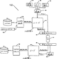
図1は、連鎖反応符号化を使用する通信システム100のブロック図である。
通信システム100において、入力ファイル101、または入力ストリーム105は、入力記号発生器110に与えられる。入力記号発生器110は、入力ファイルまたは入力ファイルストリームから1以上の入力記号(IS(0),IS(1),IS(2),...)のシーケンスを生成し、各入力記号は、値および位置を有する(図1に括弧付きの整数として示される)。上記のように、入力記号に対して可能な値、すなわち、そのアルファベットは、一般に2M個の記号のアルファベットであるので、各入力記号は、Mビットの入力ファイルを符号化する。Mの値は、一般に通信システム100を使用することによって決定されるが、汎用システムは、入力記号発生器110に入力される記号サイズを含み得るので、Mは使用ごとに異なり得る。入力記号発生器110の出力は、エンコーダ115に与えられる。
【0074】
キー発生器120は、エンコーダ115によって生成される出力記号の各群に対するキーを生成する。各キーは、どのキー発生器によって生成されたかにかかわらず、上記の方法のうちの1つ、または同じ入力ファイルに対して生成されたキーの大きな割合が固有であることを確保する任意の同等の方法によって生成される。例えば、キー発生器120は、カウンタ125の出力、固有のストリーム識別子130、および/またはランダム発生器135の出力の組合せを使用して、各キーを生成し得る。キー発生器120の出力は、エンコーダ115に与えられる。
【0075】
キー発生器120によって与えられた各キーIに基づいて、エンコーダ115は、入力記号発生器によって与えられる入力記号から記号値B(I)のセットを有する1群の出力記号を生成する。出力記号の各群のb値は、そのキーおよび1以上の入力記号のある関数に基づいて生成される。本明細書中でb値を出力記号の群の「関連付けした入力記号」または単にその「関連付け」と呼ぶ。関数(「値関数」)および関連付けの選択は、以下により詳細に記載されるプロセスにしたがってなされる。一般に、常にではないが、Mは、入力記号および出力記号に対して同じである、すなわち、入力記号は、出力記号と同じ長さである。
【0076】
いくつかの実施形態において、入力記号数Kは、関連付けを選択するためにエンコーダによって使用される。Kがあらかじめ未知の場合は(入力がストリーミングファイルの場合など)、Kは単に推定され得る。値Kはまた、入力記号に対して記憶装置を割り当てるためにエンコーダ115によって使用され得る。
【0077】
エンコーダ115は、出力記号の群を送信モジュール140に与える。送信モジュール140にはまた、キー発生器120から出力記号の各そのような群のキーが与えられる。送信モジュール140は、出力記号の群を送信し、送信モジュール140はまた、使用されるキーイング方法に依存して、出力記号の送信される群のキーについてのいくつかのデータをチャネル145を介して受信モジュール150に送信する。チャネル145は、イレーズチャネルと仮定されるが、これは、通信システム100の適切な動作に必要ではない。モジュール140、145および150は、送信モジュール140が出力記号の群およびそれらのキーについて必要な任意のデータをチャネル145に送信するように改造され、受信モジュール150が出力記号の群および可能ならばそれらのキーについてのいくつかのデータをチャネル145から受信するように改造される限り、適切なハードウェアコンポーネント、ソフトウェアコンポーネント、物理的媒体、またはそれらの任意の組合せならいずれのものでもよい。Kの値が、関連付けを決定するために使用される場合、チャネル145を介して送信され得るか、またはエンコーダ115とデコーダ155との一致によってあらかじめ設定され得る。
【0078】
上記のように、チャネル145は、インターネット、またはテレビジョン送信器からテレビジョン受信者への放送リンク、または1地点から別の地点への電話接続などの実時間チャネルであり得る。または、チャネル145は、CD−ROM、ディスクドライブ、ウェッブサイトなどの記憶チャネルであり得る。チャネル145は、実時間チャネルと記憶チャネルとの組合せでもあり得る。例えば、一人がパソコンからインターネットサービスプロバイダ(ISP)に電話回線を介して入力ファイルを送信し、その入力ファイルがウェッブサーバに格納されて、後でインターネットを介して受信者に送信される場合に形成されるチャネルである。
【0079】
チャネル145はイレーズチャネルであると仮定されるので、通信システム100は、受信モジュール150を出る出力記号の群と送信モジュール140に入る出力記号の群との間に1対1対応を仮定しない。実際には、チャネル145がパケットネットワークを含む場合、通信システム100は、任意の2つ以上のパケットの相対的順序がチャネル145を介した送信中に保存されると仮定できないとされ得る。したがって、出力記号の群のキーは、上記キースキームの内1つ以上を使用して決定され、受信モジュール150を出る出力記号の群の順序によって必ずしも決定されない。
【0080】
受信モジュール150は出力記号の群をデコーダ155に与え、受信モジュール150が受信する出力記号のこれらの群のキーについての任意のデータは、キー発生器160に与えられる。キー発生器160は、受信した出力記号の群に対するキーを再生成し、これらのキーをデコーダ155に与える。デコーダ155は、キー発生器160によって与えられたキーと対応の出力記号の群とを使用して、入力記号(再度、IS(0),IS(1),IS(2),...)を回復する。デコーダ155は、回復された入力記号を入力ファイルリアセンブラ165に与え、リアセンブラ165は入力ファイル101または入力ストリーム105のコピー170を生成する。
【0081】
(基本エンコーダ)
図2は、図1に示されるエンコーダ115の1つの実施形態のブロック図である。図2のブロック図を、ここで図3を参照して説明する。図3は、図2に示すエンコーダによって実行される処理の内のいくつかの論理等価物を示す図である。
【0082】
エンコーダ115には、入力記号および生成すべき出力記号の各群に対するキーが与えられる。示されるように、K個の入力記号が、入力記号バッファ205内に格納される。キーI(図1で示されるキー発生器120によって与えられる)は、値関数セレクタ210、群サイズセレクタ212、重みセレクタ215、および連想装置220への入力である。入力記号数Kはまた、これら4つのコンポーネント210、212、215および220に与えられる。計算器225は、値関数セレクタ210、群サイズセレクタ212、重みセレクタ215、連想装置220および入力記号バッファ205からの出力を受信するよう結合され、出力記号値の群に対する出力を有する。理解すべきことは、図2に示す要素と等価な他の構成が使用され得、これは本発明のエンコーダの1例にすぎないことである。
【0083】
動作中、K個の入力記号が入力記号バッファ205に受信および格納される。上記のように、各入力記号は、位置(すなわち、入力ファイル内の元の位置)および値を有する。入力記号は、格納される入力記号の位置が決定され得る限り、それぞれの順序で入力記号バッファ205内に格納される必要はない。
【0084】
群サイズセレクタ212は、使用される場合、キーIおよび入力記号数Kから群サイズG(I)を決定する。1つの変形において、群サイズG(I)は、すべてのIに対して同じである(すなわち、G(I)=bであり、ここでbは正の整数である)。この変形において、群サイズセレクタ212は必要ではなく、計算器225はbの値に設定され得る。例えば、群サイズは、すべてのIに対して4に設定され得る、すなわち、G(I)=b=4であり、出力記号の各群は、4つの出力記号を含む。いくつかの実施形態において、2または3などの小さな値のb、またはわずかに異なる値のG(I)を使用することは、エンコーダの効率化に役立つ。b=1の場合、その結果は、LubyIに記載のエンコーダと実質的に同じである。
【0085】
キーIおよび入力記号数Kを使用して、重みセレクタ215は、キーIを有する出力記号の群の「関連付け」となるべき入力記号の数W(I)を判定する。キーI、重みW(I)および入力記号数Kを使用して、連想装置220は、出力記号の群に関連付けられた入力記号の位置のリストAL(I)を判定する。理解すべきことは、W(I)は、連想装置220があらかじめW(I)を知らずにAL(I)を生成し得る場合、別個にまたは明確に計算される必要がないことである。AL(I)が一旦生成されると、W(I)は容易に判定される。なぜなら、それはAL(I)中の関連付けの数であるからである。
【0086】
I、W(I)およびAL(I)が一旦既知となると、出力記号の群のG(I)個の値B(I)=B_1(I),...,B_G(I)(I)は、値関数F(I)210に基づいて計算器225によって計算される。適切な値関数の1つの性質は、AL(I)中のG(I)個までの関連付けに対する未知の値が出力記号値B(I)の群およびAL(I)中の他の関連付けに対する既知の値から判定され得ることである。このステップにおいて使用される1つの好ましい値関数は、リード−ソロモン値関数である。なぜなら、それは、この性質を満足し、容易に計算され、および容易に反転されるからである。
【0087】
リード−ソロモン値関数の場合、値B(I)は、リード−ソロモン符号化スキームにしたがって、AL(I)中の関連付けの値から計算される。そのスキームにおいて、リード−ソロモン冗長記号はB(I)であり、そしてAL(I)中の入力記号とともにこれらの記号は、リード−ソロモン符号化スキームを使用して符号化される符号化ブロックを形成する。
【0088】
他の適切な値関数を代わりに使用してもよい。例えば、群サイズが1に等しい場合のXOR値関数の使用、有限体に関する多項式に基づく方法、線形系方程式に基づく方法、有限体に関するコーシー行列に基づく方法、または、他のMDS符号(そのリード−ソロモン符号は1例である)を含む。
【0089】
出力記号の群の関連付け数に依存する異なる値関数の混合がまた、使用され得る。例えば、関連付け数W(I)がG(I)に等しい場合、識別関数が使用され得る、すなわち、i=1,...,G(I)に対して、その群におけるi番目の出力記号の値はB_i(I)=IS(P_i)であり、ここでP_1,...,P_G(I)はG(I)個の関連付けの位置である。関連付け数W(I)がG(I)+1に等しい場合、i=1,...,G(I)に対して、その群におけるi番目の出力記号の値は、B_i(I)=IS(P_i)XORIS(P_i+1)であり得る、ここで、P_1,...,P_G(I)+1は、G(I)+1個の関連付けの位置である。関連付け数W(I)はG(I)+1よりも大きい場合、リード−ソロモン値関数が使用され得る。
【0090】
値関数セレクタ210が、使用される場合、キーIおよびKからの値方法または値関数F(I)を判定し、ここで、F(I)を使用してIに対する値を計算する。1つの変形において、値関数セレクタ210は、すべてのIに対して同じ方法または関数Fを使用する。この変形において、値関数セレクタ210は必要でなく、計算器225が値関数Fを構成し得る。例えば、値関数はすべてのIに対してリード−ソロモン符号化器であり得る。すなわち、出力記号値の群は、すべてのその関連付けの値に基づいてリード−ソロモン符号化器によって計算されるG(I)個の冗長記号を含む。
【0091】
各キーIに対して、重みセレクタ215は、IおよびKから重みW(I)を判定する。1つの変形において、重みセレクタ215は、キーIを使用することによってW(I)を選択して、まずランダム検索数を生成し、次いでこの数を使用して、重みセレクタ215内に格納された分布テーブル中のW(I)の値を検索する。そのような分布テーブルがどのように形成およびアクセスされるかを以下により詳細に説明する。一旦重みセレクタ215がW(I)を判定すると、この値は、連想装置220および計算器225に与えられる。
【0092】
連想装置220は、現在の出力記号に関連付けられたW(I)個の入力記号の位置のリストAL(I)を判定する。この関連付けは、Iの値、W(I)の値およびK(利用可能ならば)に基づく。一旦連想装置220がAL(I)を判定すると、AL(I)は、計算器225に与えられる。リストAL(I)、重みW(I)および、値関数セレクタ210によって与えられる値関数F(I)または予め選択された値関数Fのいずれかを使用して、計算器225は、入力記号バッファ205中のAL(I)によって参照されるW(I)個の入力記号にアクセスして、出力記号の現在の群に対する値B(I)=B_1(I),...,B_b(I)を計算する。ここでbは、群サイズセレクタ212によって与えられる群サイズG(I)または予め選択された設定値のいずれかである。AL(I)を計算するための手順の例を以下に与えるが、別の適切な手順を代わりに使用してもよい。好ましくは、その手順は、各入力記号に、出力記号の所定の群に対する関連付けとして選択される確率を略等しく与え、デコーダがそれにとって利用可能なAL(I)をまだ有していない場合にデコーダが複製し得るように選択する。
【0093】
次に、エンコーダ115は、B(I)=B_1(I),...,B_b(I)を出力する。実際は、エンコーダ115は、図3に例示する動作を実行して、すなわち、選択された入力記号のある値関数として出力記号値の群、B(I)=B_1(I),...,B_b(I)を生成する。示される例において、その値関数は、群サイズbが2に設定されたリード−ソロモン符号化であり、出力記号の群の重みW(I)は3であり、関連付けられた入力記号(関連付け)は位置0、2および3であり、値IS(0)、IS(2)およびIS(3)をそれぞれ有する。したがって、出力記号の群は、Iの値に対して以下のように計算される:
B_1(I)=RS_1(IS(0),IS(2),IS(3))
B_2(I)=RS_2(IS(0),IS(2),IS(3))
ここで、RS_i(*)は、リード−ソロモンエンコーダを引数に適用してi番目の冗長記号を生成することによって生成される記号値である。
【0094】
次に、生成された出力記号の群は、上記のように送信および受信される。ここで、出力記号の群の内いくつかが損失されるかまたはその順序がみだれた、もしくは1つ以上のエンコーダによって生成されたと仮定する。しかし、受信される出力記号の群の受信は、そのキーIの表示、および値B(I)=B_1(I),...,B_b(I)が正確であるという何らかの確実さをもって受信されると仮定する。図1に示すように、それらの出力記号の受信された群は、キー再発生器160による表示およびKの値から再構築される対応のキーとともに、デコーダ155に入力される。
【0095】
入力記号中に符号化されるのビット数M(すなわち、そのサイズ)は、アプリケーションに依存する。出力記号のサイズおよび1つの群中の出力記号数bもまた、アプリケーションに依存し得るが、チャネルにもまた依存し得る。例えば、一般的な入力ファイルが、複数のメガバイトのファイルである場合、その入力ファイルは、数千個、数万個または数十万個の入力記号に分割され、各入力記号は、数バイト、数十バイト、数百バイトまたは数千バイトである。
【0096】
いくつかの場合において、出力記号値および入力記号値が同じサイズであれば(すなわち、同じ数のビットによって表現可能か、または同じアルファベットから選択される)、符号化プロセスは、簡略化され得る。そのような場合、出力記号の群をパケットに入れるのが望ましく、かつ出力記号の各群が限られたサイズのパケットに収まる必要があり、かつ各群のサイズbが固定値に設定される場合などの出力記号値サイズが限定される場合、入力記号値サイズが限定される。キーについてのいくつかのデータが、受信器にてキーを回復するために送信される場合、好ましくは、出力記号の群は、値およびキーについてのデータが1つのパケットに収まるように十分に小さいものであり得る。
【0097】
上記のように、多くの実施において入力記号の位置は一般に連続であるが、キーは連続ではない。例えば、入力ファイルが60,000個の入力記号にまで分割されたとすると、その入力記号の位置の範囲は、0から59,999ある。上記実施のうちの1つにおいて、各キーはランダムな32ビット数として独立に選択され、出力記号の群は、連続的に生成され、送信者が停止するまで送信され得る。ここで示すように、群連鎖反応符号化は、60,000記号の入力ファイルが出力記号の任意の十分に大きな集合(60,000+いくらかの増分A)から再構築される。なお、これは、出力記号のこれらの群が出力シーケンスのどこから取り出されるかに依存しない。
【0098】
(基本デコーダ)
図4は、デコーダ155の1つの実施形態を詳細に示し、多くの部分が図2に示すエンコーダ115と共通である。デコーダ155は、値関数セレクタ210、群セレクタ212、重みセレクタ215、連想装置220、出力記号の1群を格納するバッファ405、レジューサ(reducer)415、再構築器420および再構築バッファ425を含む。エンコーダに関して、群セレクタ212および群サイズを格納するために割当てられるバッファ405中のスペースは、群のサイズが出力記号のすべての群に対して同じである場合、任意であり、使用しなくてもよい。同様に、値関数セレクタ210および値関数の記述を格納するために割当てられるバッファ405中のスペースは、値関数が出力記号のすべての群に対して同じである場合、任意であり、使用しなくてもよい。再構築バッファ425のいくつかのエントリが図示され、ここでいくつかの入力記号が再構築され、他は依然未知である。例えば、図4において、位置0、2、5および6の入力記号が回復され、位置1、3および4の入力記号はまだ回復されない。
【0099】
動作中、キーIおよび値B(I)=B_1(I),...,B_b(I)を有する受信された出力記号の各群に対して、デコーダ155は以下を行う。キーIは、値関数セレクタ210、群セレクタ212、重みセレクタ215および連想装置220に与えられる。KおよびキーIを使用して、重みセレクタ215は、重みW(I)を判定する。K、キーIおよび重みW(I)を使用して、連想装置220は、出力記号の群に関連付けられた入力記号のW(I)個の位置のリストAL(I)を生成する。必要に応じて、KおよびIを使用して、群セレクタ212は、群サイズG(I)を選択する。必要に応じて、KおよびIを使用して、値関数セレクタ210は、値関数F(I)を選択する。次に、I、B(I)、W(I)およびAL(I)、任意のG(I)および任意のF(I)は、列をなしてバッファ405に格納される。群セレクタ212、値関数セレクタ210、重みセレクタ215および連想装置220は、エンコーダ115について記載したのと同じようにデコーダ155の動作を実行する。特に、図5における群セレクタ212、値関数セレクタ210、重みセレクタ215および連想装置220によって生成される群サイズG(I)、値関数F(I)、重みW(I)およびリストAL(I)は、図4に示す対応の部分と同じキーIである。Kが入力ファイルごとに異なる場合、Kをメッセージヘッダに含むなどの任意の従来方法でエンコーダからデコーダへ通信され得る。
【0100】
再構築器420は、バッファ405を走査して、たかだか群サイズの重みを有するバッファ405に格納された出力記号の群を探す。これらの記号は、本明細書中で「復号可能なセット」のメンバと呼ぶ。上記の性質を有する値関数に対して、たかだかそれらの群サイズの重みの出力記号の群は、復号可能なセットに含まれる。なぜなら、それらの群サイズまでの入力記号の未知の値は、その出力記号の群および関連付けである他の入力記号の既知の値から判定され得るからである。当然、入力記号が、たかだかそれらの群サイズの重みを有すること以外の条件下で出力記号の1群によって復号されることを可能にし得る値関数が使用されるならば、その条件を使用して、出力記号の1群が復号可能なセットかどうかを判定し得る。明確にするために、ここで記載した例は、復号可能なセットが、たかだかそれらの群サイズの重みを有する出力記号の群であり、これらの例の、他の値関数復号可能条件への拡張は、この記載から明らかである。
【0101】
再構築器420が復号可能なセットに含まれるキーIを有する出力記号の1群を見つけた場合、その出力記号値の群は、B(I)=B_1(I),...,B_G(I)(I)であり、必要に応じて、値関数F(I)を使用してAL(I)にリストされた未知の入力記号のW(I)個の値を再構築し、再構築された入力記号は、それらの入力記号に対する適切な位置で再構築バッファ425に配置される。W(I)が厳密に群サイズG(I)より小さい場合、再構築器420は、独立した方法ですでに再構築された入力記号値を再構築し得る。この場合、再構築器420は、独立に再構築された入力記号を脱落させ、既存の再構築された入力記号を上書きし、または独立に得られた入力記号の値を比較し、それらが異なれば誤りを生成する。このように再構築器420は入力記号を再構築するが、復号可能なセット中の出力記号の群からのみ入力記号を再構築する。一旦復号可能なセットからの出力記号の1群を使用して入力記号を再構築すると、それは、バッファ405のスペースを節約するために削除され得る。「使い古した」群の出力記号を削除することはまた、再構築器420が連続してその出力記号の群に再び訪れないことを確実にする。
【0102】
まず、再構築器420は、復号可能なセットの1メンバである少なくとも1つの出力記号の群が受信されるまで待機する。一旦その出力記号の1群を使用して未知の入力記号を再構築すると、復号可能なセットは再び空となる。ただし、出力記号のいくつかの他の群が、これらのちょうど再構築された入力記号の内いくつかおよびその群サイズまでまだ再構築されない他の入力記号の関数であり得るという事実を除く。このように、復号可能なセットの1メンバから入力記号を再構築することにより、出力記号の他の群が復号可能なセットに付加される。出力記号の群を復号可能なセットに付加して低減するプロセスは、レジューサ415によって実行される。
【0103】
レジューサ415は、バッファ405および再構築バッファ425を走査して、回復された入力記号の位置をリストするリストAL(I)を有する出力記号の群を見つける。レジューサ415がキーIを有する出力記号のそのような「低減可能な」群を見つけた場合、レジューサ415は、AL(I)中の入力記号のうちでまだ再構築されていなかった入力記号値の数に等しくなるようにW(I)を再計算する。
【0104】
レジューサ415の作用は、バッファ405中の出力記号の群の重みを低減する。出力記号の1群の重みは、たかだかその群サイズに低減される場合(または、他の復号可能な条件が他の値関数に対して生じる)、その出力記号の群は、復号可能なセットの1メンバとなり、それは次に再構築器420によって作用され得る。実用においては、一旦十分な数の出力記号の群が受信されると、レジューサ415および再構築器420は、連鎖反応復号化を生成し、入力ファイルからのすべての入力記号が回復されるまで、再構築器420は復号可能なセットを復号してより多くの入力記号を回復し、レジューサ415はそれらの新しく受信された入力記号を使用してより多くの出力記号の群を低減し、それによりそれらを復号可能なセットに付加するなどする。
【0105】
図4に示されるデコーダは、記憶装置、計算サイクルまたは送信時間をあまり考慮せずに、単純な方法で入力記号を再構築する。デコーダメモリ、複合化時間または送信時間(受信される出力記号の群の数を制限する)が限定される場合、デコーダは、それら限られたリソースをよりよく使用するために最適化され得る。
【0106】
(より効率的なデコーダ)
図5は、デコーダ500のより効率的な実施の好ましい実施形態を詳細に示す。ここで、値関数は、リード−ソロモン値関数であると仮定する。さらに効率的になる可能性のある同様の実施が、リード−ソロモン値関数以外の値関数に対して適用される。図5を参照して、デコーダ500は、出力記号の群データ構造505(以下、GOSDS505と呼ぶ)、入力記号データ構造510(以下、ISDS510と呼ぶ)、復号可能なセットスタック515(以下、DSS515と呼ぶ)、受信オーガナイザ520、および回復プロセッサ525を含む。
【0107】
GOSDS505は、出力記号の群についての情報を格納するテーブルであり、ここでGOSDS505の行Rは、受信された出力記号のR番目の群についての情報を格納する。変数Rは、受信された出力記号の群の数を追跡し、ゼロに初期化される。GOSDS505は、各行に対してフィールドKEY、VALUE、およびWEIGHTを格納し、図示のフィールドは、列に組織化される。KEYフィールドは、出力記号の群のキーを格納する。VALUEフィールドは、出力記号値の群を格納する。WEIGHTフィールドは、出力記号の群の初期重みを格納する。出力記号の1群のWEIGHTは、たかだか群サイズになるまで経時的に低減され、そして入力記号を回復するために使用され得る。
【0108】
ISDS510は、入力記号について情報を格納するテーブルであり、ここで行Pは、位置Pでの入力記号についての情報を格納する。各行に対して、ISDS510は、最終的に回復された入力記号の値になるREC_VALフィールド、すべての値が「no」に初期化され、入力記号が回復されたかどうかを示すREC_INDフィールド、およびRLフィールド用の記憶装置を含む。入力記号が回復される場合、入力記号のREC_INDは、「yes」に変更される。RL列は、すべてが「空リスト」値に初期化される。関連付けとして入力記号を有する出力記号の群が受信されるので、出力記号の群のGOSDS505における行数が、入力記号に対するRLリストに付加される。
【0109】
DSS515は、復号可能なセットについての情報を格納するスタックである。変数Sは、復号可能なセットのサイズを追跡し、それをゼロに初期化する。DSS515において、列OUT_ROWは、出力記号の群のGOSDS505における行数を格納する。
【0110】
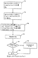
1つの実施形態において、デコーダ500は、以下のように、そして図6のフローチャートに示すように動作され、図6の対応するステップは、プロセスの説明において括弧で示す。まず、ISDS510は、上記のように初期化され、RおよびSの両方がゼロに初期化される(605)。出力記号の1つの新しい群が受信されると(610)、すなわち、キーIおよび出力記号値の群B(I)=B_1(I),...,B_G(I)(I)、GOSDS505においてKEY(R)がIに設定され、VALUE(R)がB(I)=B_1(I),...,B_G(I)(I)に設定される(615)。次に、受信オーガナイザ520が呼び出されてGOSDS505の行Rに格納されたキーIを有する受信された出力記号の群が処理される(620)。これは、図7のフローチャートに示すように、ISDS510に格納された情報を適切に使用して、情報をGOSDS505およびDSS515に付加するステップを含む。次に、Rを1だけインクリメントし(625)、次の出力記号の群をGOSDS505の次の行に格納させる。次に、回復プロセッサ525が呼び出され、復号可能なセット中の出力記号の群を処理し、出力記号の新しい群を復号可能なセットに付加する(630)。これは、図8aおよび/または8bのフローチャートに示すように、ISDS510およびGOSDS505の一部を適切に使用および改変することによって、DSS515に格納された復号可能なセットに付加および削除するステップを含む。デコーダ500は、回復された入力記号の数を追跡し、この数がKに達した場合、すなわち、すべての入力記号が回復された場合、デコーダ500は、首尾よく終了し、そうでなければステップ610に戻り次の出力記号の群を受信する(635および640に示す)。
【0111】
受信オーガナイザ520の動作を説明するフローチャートを図7に示す(図9から12を参照)。値B(I)=B_1(I),...,B_G(I)(I)およびキーIを有する出力記号の1群が到着した場合、受信オーガナイザ520は、以下の動作を実行する(図7を参照)。重みW(I)は、IおよびKから計算され(705)、関連付けの位置のリストAL(I)は、I、W(I)、およびKから計算される(710)。図11〜12は、W(I)の1計算の詳細を示し、図9〜10は、AL(I)の1計算の詳細を示す。
【0112】
再度図7を参照して、リストAL(I)上の各位置Pに対して、入力記号Pが回復されない場合、すなわち、ISDS510においてREC_IND(P)=「no」の場合、Rは、ISDS510中のリストRL(P)に付加され、そうでなく、入力記号Pが回復される場合、すなわち、ISDS510においてREC_IND(P)=「yes」の場合、W(I)は1だけデクリメントされる(720)。次に、WEIGHT(R)は、GOSDS505においてW(I)に設定される(725)。次に、WEIGHT(R)は、G(I)と比較される(730)。WEIGHT(R)がたかだかG(I)である場合、出力記号の群は、復号可能なセットに付加される、すなわち、OUT_ROW(S)がDSS515においてRに設定され、Sの値が1だけインクリメントされる(735)。
最後に、受信オーガナイザ520が戻る(740)。
【0113】
図8aに、図9〜12を参照して回復プロセッサ525の1つの動作を記載するフローチャートを示す。その動作中、回復プロセッサ525はまず、復号可能なセットが空かどうか、すなわち、S=0かどうかを確かめるためにチェックし、そうであればただちに呼び出し元へ帰る(805、810)。復号可能なセットが空でなければ、Sは1だけデクリメントされ(815)、出力記号の群の行番号R’をDSS515からロードする(820)。次に、出力記号の元のキー、GOSDS505からのKEY(R’)がIへロードされ(835)、元の重みW(I)および群の関連付けの元のリストAL(I)を計算する(840,845)。AL(I)におけるのすべての入力記号がすでに回復された場合、すなわち、AL(I)におけるすべてのPに対してREC_IND(P)=「yes」ならば(847)、回復プロセッサ525は、復号可能なセットのその要素の処理を停止し、次のステップを処理し続ける。そうでなければ、GOSDS505における行番号R’に格納された出力記号の群を使用して、ISDS510におけるAL(I)にある入力記号すべての未知の値を回復する。これは、リード−ソロモンデコーダを利用することによって実行され、出力記号値の群およびAL(I)における入力記号の既知の値を使用してAL(I)におけるG(I)個までの入力記号の未知の値を回復する(850)。次に、入力記号値が回復されるすべての位置Pに対して、REC_VAL(P)は、ISDS510における回復された入力記号値に設定され(852)、REC_IND(P)が「yes」に設定され、入力記号がISDS510において回復されたことを示す(852)。
【0114】
図8aにおいて示すプロセスの1つの変形例を図8bに示す。そこで、出力記号の各群が処理されるステップ850、852、855および860を実行する代わりに、図8bのステップ851、853、856および861に示すように、R’の値が後の処理のために実行スケジュールに格納される。保留された実行処理の例を、ステップ870、875、880および885により示されるステップを含む図8cに示す。この変形例において、図6に示すフローチャートは、ステップ605においてEをゼロに初期化することによって改変される。実行スケジュールの保留された処理は、受信した記号がファイル全体を復号するのに十分であるとデコーダが判定した後、例えば、すべての入力記号が回復可能であると分かった後のステップ640にて行われ得る。いくつかの場合において、特に入力記号が大きい場合、スケジュールの実行は、入力ファイルまたはその部分が受信器側で必要となるまで保留され得る。
【0115】
いずれの変形例においても、すなわち、図8aまたは図8bのいずれかにおいて、ステップ855または856で、ちょうど回復された出力記号の群または回復されるはずだった出力記号の群に対し、関連付けとしての入力記号は、これらの入力記号が回復されたこと、または回復されるはずだったことを反映するように改変される。ちょうど回復された、または回復されるはずだった各位置Pに対して、GOSDS505における出力記号のこれらの群の行番号は、RL(P)内に格納される。RL(P)における各行番号R’’に対して、WEIGHT(R’’)が1だけデクリメントして、GOSDS505の行R’’における出力記号の群の関連付けとして位置Pにおける入力記号の回復を反映させる。この改変により、GOSDS505の行R’’における出力記号の群が群サイズに等しい重み、すなわち、WEIGHT(R’’)=G(KEY(R’’))になる場合、出力記号のこの群は、OUT_ROW(S)をR’’に設定し、かつSを1だけインクリメントすることによって復号可能なセットに付加される(855または856)。最後に、リストRL(P)上の出力記号の群の行番号を格納するために使用されるスペースをフリースペースに戻し(860または861)、処理はステップ805に続く。
【0116】
(連想装置の実施)
1群の出力記号キーから関連する入力記号へのマッピング(すなわち、重みW(I)、およびキーIに対する関連付けの位置のリストAL(I)の決定)は、種々の形態をとり得る。W(I)は、同じキーIに対してエンコーダおよびデコーダの両方によって同じ値(送信者および受信者のそれぞれにおいて)であるように選択されるべきである。同様に、AL(I)は、同じキーIに対してエンコーダおよびデコーダの両方によって同じ位置のリストを含むように選択されるべきである。連想装置は、Iならびに通常W(I)およびKからAL(I)を計算または生成するオブジェクトである。
【0117】
1つの実施形態において、W(I)およびAL(I)は、ランダムプロセスを模倣するように設計された方法で判定される。エンコーダおよびデコータが同じキーに対して同じ結果を生成するという要件を満足するために、擬似ランダムシーケンスが、キーをシードにしてエンコーダおよびデコーダの両方によって生成され得る。擬似ランダムシーケンスの代わりに、本当のランダムシーケンスが、W(I)および/またはAL(I)の生成のために使用され得るが、それが有用であるためには、W(I)およびAL(I)を生成するために使用されたランダムシーケンスが受信者に通信される必要があり得る。
【0118】
図4において示すデコーダにおいて、バッファ405は、関連付けの位置の出力記号リストの各群の記憶装置、すなわち列でラベルされたAL(I)内に記憶装置を必要とする。図5に示すより効率的なデコーダは、この記憶装置を必要としない。なぜなら、関連付けの1リストは、例えば図9〜10に示すように、必要に応じて再計算されるからである。これらの計算が必要に応じて速やかに行われ得る場合にのみ、記憶装置を節約するために毎回関連付けリストを再計算する際に利点がある。
【0119】
連想装置220の好ましい実施形態が図9に示され、図10に示すプロセスにしたがって動作する。この連想装置は、エンコーダおよびデコーダにおいて使用され得る。エンコーダは1回に1より多くのAL(I)を格納する必要が通常ないので、エンコーダでのAL(I)のための記憶装置にはあまり関心がないが、同じプロセスをエンコーダおよびデコーダの両方で使用して、AL(I)に対する値が両方の場所で確実に同じとなるようにすべきである。
【0120】
連想装置220への入力は、キーI、入力記号数K、および重みW(I)である。出力は、キーIを有する出力記号の群の関連付けのW(I)個の位置のリストAL(I)である。図9において示すように、アソシエータは、ランダムビットのテーブルASSOC_RBITS905および計算器ASSOC_CALC910を含む。特定のAL(I)が生成される前に、入力ファイルのサイズは、入力記号数が素数となるように調節される。このように、入力ファイルがK個の入力記号で開始する場合、Kより大きいかまたはKに等しい最小素数Pが識別される。PがKよりも大きい場合、P−K個のブランク(例えば、ゼロに設定される)入力記号が入力ファイルに付加され、KがPに再設定される。この改変された入力ファイルに対して、関連付けの位置のリストAL(I)は、図9および10に示すように計算される。
【0121】
この実施形態において、ASSOC_CALC910は、以下に記載され、かつ図10のフローチャートに示すように動作する。第1ステップは、キーI、入力記号数KおよびランダムビットASSOC_RBITS905のテーブルを使用して、Xが少なくとも1かつたかだかK−1であり、Yが少なくともゼロかつたかだかK−1である性質を有する2つの整数値XおよびYを生成することである(1005)。好ましくは、XおよびYは、独立であり、それぞれの範囲内で一様分布する。次に、W(I)個のエントリを有する配列V[]が、AL(I)の記憶のために、そのメンバが計算される際に初期化される(1010)。V[]は、1つのリストに対する一時記憶装置にすぎないので、バッファ405(図4を参照)のAL(I)列よりもずっと少ないメモリを占めるだけであり得る。V[0](これは、リストAL(I)の第1番目の要素)がYに設定される(1015)。次に、1で始まりW(I)−1で終わるJのすべての値に対して、V[J]の値は、ステップ1020〜1050に示すように、(V[J−1]+X) mod Kに設定される。Kが素数であり、かつW(I)がたかだかKであるので、V[]値のすべてが固有である。図示のように、「mod K」演算は、簡単な比較および減算演算であり得る、すなわち、ステップ1035および1040。このように、出力記号の所定群の関連付けの位置のリストを生成するプロセスは、非常に効率的である。
【0122】
AL(I)を計算する上記アプローチの1つの利点は、関連付けの位置の分布に十分な変化を生成して、復号化アルゴリズムを、W(I)を選択するための良好な手順と合わされる場合、高い確率かつ最小の受信オーバーヘッドで動作させることを確実にする(すなわち、入力ファイルは、出力記号のK/b個よりわずかに多い群を受信した後、回復される。ここで入力記号および出力記号は同じ長さとする)。
【0123】
AL(I)が図10に示すように計算され、ランダムビットASSOC_RBITS905のテーブルが送信者と受信者との間で秘匿される場合、通信システム100は、安全な通信システムとして使用され得る。なぜなら、AL(I)のシーケンスを知らずに、受信したストリームを復号化することは、不可能ではないが、困難であるからである。この特徴はまた、AL(I)を計算または生成する方法である限り、AL(I)を計算または生成する他の方法を使用する通信システムに適用し得る、また、好ましくは、発生器AL(I)を計算する方法において使用されるシードは、秘匿される。
【0124】
(重みセレクタ実施例)
エンコーダ/デコーダの性能および効率は、重みの分布に依存し、いくつかの分布は、他の分布より良好である。重み選択の動作の局面を以下に議論し、その後いくつかの重要な重み分布を説明する。図11のブロック図および図12のフローチャートを使用してこれらの概念を例示する。
【0125】
図11に示すように、重みセレクタは、2つのプロセスWT_INIT1105およびWT_CALC1110、ならびに2つのテーブルWT_RBITS1115およびWT_DISTRIB1120を含む。プロセスWT_INIT1105は、第1のキーが通過してテーブルWT_DISTRIB1120を初期化した場合に1度だけ呼び出される。WT_DISTRIB1120の設計は、システムの重要な局面であり、後でずっとより詳細に考察される。プロセスWT_CALC1110は、各呼び出しごとに呼び出されて、キーIに基づいて重みW(I)を生成する。図12のフローチャートに示すように、WT_CALC1110は、キーおよびテーブルWT_RBITSに格納されたランダムビットを使用して、乱数Rを生成する(1205)。次に、Rの値を使用して、テーブルWT_DISTRIB1120における行番号Lを選択する。
【0126】
図11に示すように、WT_DISTRIB1120のRANGE列におけるエントリは、値MAX_VALで終了する正の整数の増加シーケンスである。Rに対する可能な値のセットは、ゼロおよびMAX_VAL−1との間の整数である。所望の性質は、Rが、可能な値の範囲においてどの値になるのも等しく確からしいことである。Lの値は、RANGE(L−1)≦R<RANGE(L)を満足するLを見つけるまでRANGE列を検索することによって決定される(1210)。一旦Lが見つかると、W(I)の値がWT(L)に設定され、これは戻された重みである(1215、1220)。図11において、図示のテーブル例に対して、Rが38,500に等しい場合、Lが4であることが分かり、したがって、W(I)はWT(4)=8に設定される。
【0127】
重みセレクタおよび連想装置を実施する他の変形例は、Iを擬似ランダムに生成し、IからW(I)およびAL(I)を直接生成するステップを含む。明らかなように、W(I)は、AL(I)を調べることによって決定され得る。なぜなら、W(I)は、AL(I)における関連付けの数に等しいからである。この説明から、W(I)個の値を生成する多くの他の方法は、説明したばかりのシステムと等価であり、WT_DISTRIBによって規定される分布を有する1セットのW(I)値を生成するということが明らかである。
【0128】
W(I)が図12に示すように計算され、ランダムビットWT_RBITS1115のテーブルが送信者と受信者との間で秘匿される場合、通信システム100は、安全な通信システムとして使用され得る。なぜなら、W(I)のシーケンスを知らずに、受信したストリームを復号化することは、不可能ではないが、困難であるからである。この特徴はまた、W(I)を計算または生成する方法である限り、W(I)を計算または生成する他の方法を使用する通信システムに適用し得る、また、好ましくは、発生器W(I)を計算する方法において使用されるシードは、秘匿される。
【0129】
(別のデコーダ)
この開示を読むと、受信器は、上記の実施例よりも効率的に動作し得ることが当業者に明らかである。例えば、受信器は、パケットをバッファし、1群のパケットが到着したときだけ回復ルールを適用すればより効率的であり得る。この改変は、後の不必要な動作を行う際にかかる計算時間を低減し、コンテクストスイッチングによるオーバーヘッドを低減する。特に、デコーダは、少なくともK個の出力記号(同じサイズの入力記号および出力記号を仮定する)がパケット単位で到着する前に、K個の入力記号の元のファイルを回復することは望めないので、復号化プロセスを開始する前に少なくともK個の出力記号が到着するまで待機することが有益であり得る。
【0130】
図13は、上記の概念を含み、図6のデコーダによって使用されるプロセスの改変例である復号化の異なる方法を示す。2つの方法間の主な違いは、図13の方法が1315に示すように、バッチ単位で出力記号の群を受信することである。第1のバッチのサイズは、到着する出力記号の総数がK+Aであるように設定され、ここで、Aは、入力記号数Kの小さな部分である(1310)。出力記号の群の第1のバッチが受信された後で、出力記号の群は、出力記号の群を処理するために受信オーガナイザ520を使用するステップ(1340)と、復号可能なセットを処理し、たかだかそれらの群サイズであり低減された重みを有する出力記号の群から入力記号を回復するために回復プロセッサ525を使用するステップ(1350)とを組み合わせて、前記のように処理される。K個の入力記号のすべてを回復することを、出力記号の群の第1のバッチを使用して達成できない場合、各バッチがさらなるG個の出力記号を含む、出力記号のさらなるバッチが、すべての入力ファイルが回復されるまで受信および処理される。
【0131】
デコーダの補助データ構造に必要な記憶装置をできるだけ低減することは、利点である。すでに説明したように、出力記号の各群に対する関連付けのリストのための記憶装置は必要でない、なぜなら、必要に応じて、連想装置220を使用して、それらのリストを速やかに計算し得るからである。まだ回復されない入力記号の各々に対して、関連付けとして入力記号を有する出力記号の群のGOSDS505における行番号を格納するために別の記憶装置が必要である。すなわち、図5のテーブルISDS510におけるRL列に示されるリストのためのスペースが必要である。図8のステップ855においてすでに説明したように、この格納を使用すると、所定の入力記号が再構築された場合、どの出力記号の群が低減可能かを速やかに識別し得る。それが効率良くなされなければ、これらのリストに必要な記憶装置は、すべての入力記号を回復するために使用される出力記号のすべての群の関連付けの総数に比例し得る。
【0132】
(予めソートするデコーダ)
次に、図14および15を参照して、デコーダのより好ましい実施形態を説明する。図14は、デコーダを構成する部分を示す。それらは、図5に示すものと同じであるが、ただし、テーブルWEIGHT SORT1405および図8bにおいて説明されるように形成された実行スケジュールを格納するために使用されるEXECUTION LIST1420が追加される点で異なる。出力記号の群のGOSDS505における行番号のバッチを格納するために、テーブルWEIGHT SORTが使用され、それらは受信される際に、重みの昇順で格納される。WT_VAL列を使用して、重みを格納し、ROW_LIST列を使用して、GOSDS505における出力記号の群の行番号を格納する。一般に、重みWT_VAL(L)を有する出力記号のすべての群の行番号は、ROW_LIST(L)に格納される。このテーブルを使用して、図15のステップ1520に示すように、重みの昇順で出力記号の群のバッチを処理する。出力記号の低い重み群は、入力記号を回復するためにそれほど集中して計算に使用せず、出力記号の群の重みが大きいほど、それらの関連付けのほとんどがただちに回復されるということがあり得る。したがって、それは、リンク記憶装置スペース(デコーダは、回復された入力リンクによって使用されるスペースを回復し得、処理中の出力記号の群はまだ未回復のわずかな関連付けを有する)を実質的に節約する。
【0133】
出力記号の群を適切なサイズのバッチで重みの昇順に処理することは、メモリ要件および処理要件を下げる。
【0134】
図15に示すように、出力記号の群においてK個よりわずかに多い出力記号(図ではK+A個の出力記号によって示す)は、いずれの処理の開始よりも前に到着することが許される(1515)。ここで、入力ファイルにおける同じサイズの入力ファイルおよび出力ファイル、ならびにK個の入力記号を仮定する。初めに、デコーダは、群におけるK+A個の出力記号の受信を単に待機する。なぜなら、デコーダは、K+A個の出力記号より少ない出力記号から入力ファイルをどうしても回復し得ないと予想でき、おそらくK個より少ない出力記号から任意の入力ファイルを回復し得ない。実用上は、5・√KがAに対して良好な値であることが分かった。
【0135】
出力記号の受信された群のGOSDS505における行番号は、図14のテーブルWEIGHT SORT1405において重みの昇順で格納される(図15のステップ1515)。Tが、そのときの1とTとの間のLの値に対する出力記号の重みの可能な群の数である場合、リストROW_LIST(L)は、重みWT_VAL(L)の出力記号の受信されたすべての群を含み、ここで1=WT_VAL(1)<WT_VAL(2)<WT_VAL(3)<...<WT_VAL(T)であり、かつWT_VAL(T)が出力記号の任意の群のうちの最大の重みである。次に、ステップ1520に示すように、図15に示すデコータの動作の残りは、図13に示すデコーダとまったく同じであるが、ただし、出力記号の群が重みの昇順で処理されることを除く。
【0136】
通常、K+A個の出力記号は、すべての入力記号を回復するのに十分であり得る。しかし、全部でK+A個の出力記号を含む出力記号のいくつかのセット群は、すべての入力記号を回復するのに十分でないことがある。そのような場合、G個のさらなる出力記号のバッチは、群単位で受信され、そしてすべての入力記号が回復されるまで処理される。Gに対する良好な設定は、√Kである。
【0137】
図16〜19は、図15において記載するプロセスの実行例の1スナップショットを示す。この例において、群サイズは、すべての群に対して2であり、出力記号の4個の群(16030、16035、16040、16045)は、図16において矢印つきの線で示す関連付け(16000、16005、16010、16015、16020、16025)とともに受信されている。まず、キー23および値(A,D)、キー159および値(RS_1(A,E,F),RS_2(A,E,F))、キー33および値(B,C)、ならびにキー835および値(RS_1(C,F,G,H),RS_2(C,F,G,H))を有する出力記号の群(第1および第3の出力記号の群は、重み2を有し、その値関数が識別関数であり、第2および第4の群は、それぞれ重み3および重み4を有し、その値関数がリード−ソロモン値関数である)が、図17に示すようにGOSDS505に受信および格納される。GOSDS505における行番号は、図18に示すように、出力記号の重みに対応する行においてROW_LIST中に格納される。重み2の出力記号の群は、GOSDS505の行0および行2にある。このように、ROW_LIST(0)は、重みWT_VAL(0)=2を有する出力記号の群に対応し、図18に示すように、行番号0および2を含む。同様に、WT_VAL(1)=3であり、かつROW_LIST(1)は1を含み、WT_VAL(2)=4であり、かつROW_LIST(2)は3を含む。
【0138】
プロセスのこの時点で、重み昇順にした出力記号の最初の2つの群が処理されており、GOSDS505の行1における出力記号の第3の群は、受信オーガナイザ520によって処理されており、出力記号のこの第3の群が回復プロセッサ525によってちょうど処理されるところである。行0および2における出力記号の群が、スケジュールにすでに付加され、それぞれ位置0、3、1および2で最終的に入力記号を回復する。GOSDS505の行3における出力記号の群は、まだ回復されてない位置5、6および7の3つの関連付けを有し、したがって、ISDS510における位置5、6および7からGOSDS505における行3に戻るリンクが存在する。GOSDS505の行1における出力記号の群は、位置0、4、および5において3つの関連付けを有する。位置0における関連付けは、回復されたものとしてすでにマークされており、したがって、そこから行1に戻るリンクは存在しない(それにより、出力記号のこの群の重みが3から2に低減され、このことは、一旦回復プロセッサ525が実行されると位置4、5、6および7における残りの入力記号の回復をトリガする)。位置4および5における関連付けは回復されず、したがって受信オーガナイザ520は、ISDS510における位置4および位置5からGOSDS505における行1へのリンクを付与する。これはすべて、図17に示される。このように、プロセスのこの時点で、入力記号から、それらを関連付けとして有する出力記号の群へ戻る全部で5つのリンクだけが使用される。これは、あらゆる入力記号から、それを関連付けとして有するあらゆる出力記号の群へのリンクを使用する単純な実施例に遜色がない。この例において、このようなリンクが11可能である。
【0139】
一般に、リンク用の格納スペースの節約が、図13に記載したプロセスよりも図14および15において記載したプロセスを使用する場合、劇的に低減する。例えば、入力記号数が50,000の場合、スペースの節約は、一般にリンクスペースにおいて10〜15倍である。この低減の理由は、重みのより小さい出力記号の群は、プロセスの終了時より開始時に入力記号を回復する可能性がより大きく、重みのより大きな出力記号の群は、プロセスの開始時より終了時に出力記号の群を回復する可能性がずっとより大きい。したがって、重みの昇順で出力記号の群を処理することは意味のあることである。図13よりも図14および15に記載するプロセスのさらなる利点は、復号化が一般に30%〜40%速くなることである。これは、重みのより小さい出力記号の群が、重みのより大きい出力記号の群よりも、入力記号を回復するために使用される可能性が大きく(なぜなら、重みのより小さい出力記号の群が先に考慮されるからである)、かつ特定の入力記号を回復するコストは、それを回復するために使用される出力記号の群の重みに直接依存するからである。
【0140】
図19は、この例の完全な実行スケジュールを示し、実行時に、群サイズ2を有する出力記号の4個の群に基づいて8個の入力記号すべてを回復し得る。
【0141】
(重み分布の選択)
重要な最適化は、入力ファイルをできるだけ少ない出力記号の群を用いて完全に再構築し得るように符号化プロセスを設計することである。この最適化は、送信時間および帯域幅がコスト高または制限される場合、または入力ファイルが、さらなる出力記号の群を待つことなく速やかに復号化されなければならない場合、役に立つ。一般に、入力ファイルの再構築に必要な十分な出力記号数は、元の入力ファイルにおける入力記号数よりもわずかに大きい(同じサイズの入力記号および出力記号を仮定する)。入力ファイルよりも少ないビットを受信した場合、任意の入力ファイルは回復され得ないことを示し得る。したがって、完全な符号化スキームは、入力ファイルと同じビット数を符号化する任意の出力記号の群のセットから入力ファイルを回復することが可能であり得、符号化効率の1つの尺度は、予期される条件下で必要な予備のビットがどれくらい少ないかである。
【0142】
図5に示すデコーダにおいて、最大効率は、デコーダがちょうどK個の出力記号を受信した後で回復プロセッサ525が最後の未知の入力記号を回復する場合に得られる。K個より多い出力記号が、すべての入力記号が回復され得る時間までにデコーダによって受信されたならば、入力ファイルの回復に必要でない、または使用されない出力記号の群が受信されたであろう。最大効率が良好である間、それを目標とすることは、再構築が完全になる前にDSS515が空になり得る危険によって調節されるべきである。言い換えると、最大効率において、復号可能なセットのサイズは、ちょうど再構築が終了する際にゼロとなるが、符号化/復号化は、復号可能なセットのサイズが再構築の終了前にゼロとなるわずかの確率しかないように、K+A個の出力記号を使用して調整されるべきであり、そのため群に含まれるG個の出力記号のさらなるセットは必要でない。
【0143】
この点を図20に例示する。この図は、復号可能なセットのサイズ対再構築された入力記号数のプロットを示す。ここで、デコーダは、以下に記載の理想の分布に対して、出力記号のK/b個の群を用いて動作し、各群はサイズbを有する。この例において、A=0、すなわち、K個の入力記号のすべてを復号するために、群に受信された出力記号数は、可能な数の最小数である(入力記号および出力記号は同じサイズと仮定する)。理解すべきことは、そのプロットが、重みおよび関連付けを決定するための任意の所定関数に対して異なり、また出力記号のどの特定の群を受信したかに依存して異なり得ることである。そのプロットにおいて、復号可能なセットサイズの予想サイズは、最初は1であり、回復プロセスを通して1を維持する。このように、予想される挙動においては、次のb個の入力記号を回復するために使用され得る、復号可能なセットにおける出力記号の1群が常に存在する。図20はまた、理想の分布の実際の挙動の例を示す。この実際の実行において、復号可能なセットは、回復が完了する前は、すなわち、100,000個の入力記号のうちの2つのみが回復された後は、空であることに留意されたい。理想の分布の実際の挙動は、一般的である、すなわち、理想の分布に対して、ランダムなゆらぎはほとんど常に、すべての入力記号が回復される前に復号可能なセットを空にし、このため、以下に記載のように、よりロバストな分布が必要である。
【0144】
効率は、復号可能なセットにおける出力記号の群が、関連付けの値を再構築するために使用される場合に、その群サイズより厳密に小さい未知の入力記号を関連付けとして有する回数を限定することによって、向上される。これは、W(I)を生成するための関数を適切に選択することによって達成され得る。
【0145】
このように、出力記号の十分な群を受信することによって、入力ファイルを任意の所望の確実度で完全に回復することが可能である一方で、Aの何らかの小さい値に対してK+A個程度に少ない出力記号(入力記号および出力記号は同じサイズと仮定する)を用いて完全な入力ファイルを含むK個の入力記号を回復する確率が高くなるように群連鎖反応符号化通信システムを設計することが好ましい。Aの最小値がゼロであり、各出力記号がK個の入力記号のすべてに依存する標準的なリード−ソロモン符号化を使用する場合などのいくつかの符号化スキームにおいて達成され得るが、これにより、符号化および復号化時間が遅くなる。Aとして何らかの小さい非ゼロ値を許容することによって、改善された通信システムが得られ得る。
【0146】
小さい値のAは、群サイズ、出力記号の群に対する重み分布(すなわち、すべてのIについてのW(I)の分布)、および出力記号の群についての関連付けの分布(すなわち、すべてのIについてのAL(I)のメンバーシップ)を決定するための適切な分布を使用することによって、群連鎖反応符号化において達成され得る。強調すべきことは、復号化プロセスが群サイズ、重み分布および関連付けの選択についての分布にかかわらず適用され得るが、好ましい実施形態は、群サイズ、重み分布および特に最適に近い性能として選択された関連付けの選択についての分布を使用し得る。実際、選択した分布の小さな変化によって性能はほんのわずかしか変化し得ないので、多くの分布が良好に機能し得る。
【0147】
1つの好ましい実施形態による分布を決定するための方法論をここで説明する。この実施形態において、出力記号のすべての群の群サイズは、固定された正の整数bと同じ値bである。使用される実際の重み分布は、理想の数学的分布に基づく。理想の重み分布において、重みW(I)は、「理想」の確率分布にしたがって選択される。最小の重みはbであり、最大の重みはKである。ここで、Kは、入力記号数である。理想の分布において、iの値に等しい重みが以下の確率pを用いて選択される:
i=bの場合、p=b/K;および
i=b+1,...,Kの場合、p=b/(i(i−1))
一旦重みW(I)が選択されると、W(I)個の関連付けられた入力記号のリストAL(I)がランダムに(必要ならば、擬似ランダムに)独立かつ均一に選択され、選択された関連付けの全てが確実に異なるようにする。このように、第1の関連付けは、K個の入力記号からランダムに選択される(各入力記号は、選択される確率が1/Kである)。次に、第2の関連付け(W>1の場合)は、残りのK−1個の記号からランダムに選択される。上記の重み確率分布は、システムが予想通り正確に挙動するならば、正確に出力記号のK/b個の群がすべての入力記号を復号および回復するのに十分であり得るという性質を有する。理想の分布に対するこの予想される挙動は、図20において実線で示される。しかし、重みおよび関連付けの選択のランダム性質のために、かつ出力記号の群の任意のセットが復号化プロセスにおいて使用されるために、プロセスは、必ずしもそのように挙動し得ない。理想の分布に対する実際の挙動の例を図20において点線で示す。このように、理想の重み分布は、実用上はいくらか改変されなければならない。
【0148】
一般に、所定の設定に対する最良のパラメータは、コンピュータシミュレーションによって見つけられ得る。しかし、理想の重み分布に関する簡単な変形例は、効果的なオプションである。この簡単な変形例において、理想の重み分布は、重みbを有する出力記号の群および出力記号の大きな重みを有する群の確率を上げることによってわずかに改変されて、K個すべての入力記号が回復される前に復号可能なセットが空になる確率を低減する。出力記号の重みbを有する群を余分に供給すると、回復プロセスが入力記号の回復の終了近くになるまで、そのプロセスが出力記号の重みがたかだかbである群を使い果たす(すなわち、復号可能なセットを空にする)確率を低減する。出力記号の大きな重みの群を余分に供給すると、回復プロセスの終了近くで、各々まだ回復されない入力記号に対して、関連付けとしてその入力記号およびまだ回復されない関連付けとしてたかだかb−1個の他の入力記号を有し得る出力記号の少なくとも1つの群が存在する確率を増加する。
【0149】
より詳細には、改変された重み分布は以下の通りである:
i=bの場合、p=n・b・R1/K;
i=b+1,...,(K/R2−1)の場合、p=n・b/(i(i−1)(1−iR2/K));および
i=K/R2,...,Kの場合、p=n・HW(i)
ここで、Kは入力記号数であり、R1およびR2は調節可能なパラメータ、ならびにnはp値のすべての合計が1となるように使用される正規化因子である。
【0150】
HW(i)ならびにR1およびR2としてサンプル値の計算を、添付書類Aにおいて詳細に示す。そこで、C++の記号nStartRippleSize、nRippleTargetSizeおよびnSymbolsは、それぞれ上記式のR1、R2およびKに対応する。
【0151】
この改変された分布は、理想の数学的重み分布に同様であり、重みbおよびさらに大きな重みを有する出力記号のさらに多くの群、ならびにそれにしたがって再設計された分布を有する。改変された分布において示されるように、R1は、重みbの記号の複数の増加した確率を決定するのと同様に、出力記号の重みbの群の初期の割合を決定し、R2は、「より大きな」重みと「それほど大きくない」重みとの間の境界を決定する。
【0152】
R1およびR2に対する良好な選択は、一般にK/bに依存し、経験的に決定され得る。例えば、R1を1.4×(K/bの平方根)に等しくし、R2を2+2.1×(K/bの四乗根)に等しくすると、実用上うまくいく。したがって、K=4000およびb=5の場合、R1=39およびR2=13に設定するとうまくいく。Kが64000およびb=2の場合、R1=250およびR2=30に設定するとうまくいく。R1およびR2のより詳細な計算を、添付書類Aに示す。図21は、この分布の予想される挙動が、回復プロセス全体にわたって復号可能なセットを適度に大きくしたままにするので、実際の実行下では、予想される挙動からのランダムなゆらぎは、すべての入力記号が回復される前に復号可能なセットを空にする見込みはない。重み分布の適切な設定によって、いかなる損失条件下においても、最小数の出力記号を受信すれば高い確率で入力記号のすべてを回復することを確実なものとする。
【0153】
上記の再構築プロセスは、トルネード符号に対して使用されるものと同様であるが、符号を形成するために使用される異なるプロセスによって、極端に異なる効果を生じる。特に、上記のように、群連鎖反応符号化に必要なメモリは、トルネード符号に必要なメモリよりも著しく小さく、種々の状況における群連鎖反応符号化の使用の容易さは、いくらかのスピードを犠牲にする可能性はあるが、トルネード符号のそれをはるかに超える。そのプロセスの基礎をなす数学的詳細は、以下により詳細に説明される。
【0154】
(いくつかの群連鎖反応符号の性質)
生成され、そしてチャネルを介して送信される出力記号の群の数は、他の符号化スキームと同様に、群連鎖反応符号化を用いても制限されない。なぜなら、キーは、入力記号に対して1対1対応を有する必要がなく、Iの異なる値の数は、入力記号数の何らかの小さな一定の割合に制限されないからである。したがって、復号可能セットが、入力ファイルが再構築される前に空になる場合でさえ、復号プロセスが失敗しない可能性がある。なぜなら、デコーダが、必要とされるより多くの出力記号の群を集めて、重みがその群サイズである出力記号の群を少なくともさらに1つ得ることができる。その群サイズの重みの出力記号からなるその群が受信されると、それは、復号可能なセットに置かれ、連鎖反応効果によって、前に受信された出力記号の群をたかだかそれらの群サイズの重みに低減させるので、それらは入力記号の再構築のために使用され得る。
【0155】
上記の例のほとんどにおいて、入力および出力記号の群は、同じ数のビットとして符号化し、出力記号の各群は、1つのパケットに配置される(1パケットは、送信の1単位であり、完全に受信されるか、または完全に損失される)。いくつかの実施形態において、通信システムは、各パケットが出力記号の数個の群を含むように改変される。次に、出力記号値のサイズは、(変化し得る)群サイズを含む多くのファクタに基づいて、最初にファイルを入力記号に分割した際の入力記号のサイズによって決定されるサイズに設定される。符号化プロセスは、実質的に変更されないままであり得る。ただし、出力記号の群が、各パケットが受信される際に、ひとまとまりで到着し得ることを除く。
【0156】
入力記号および出力記号サイズの設定は、通常、ファイルのサイズおよび出力記号の群が送信される通信システムによって決定される。例えば、通信システムは、データのビットを規定サイズのパケットにグループ化するか、または他の方法でビットをグループ化する場合、記号サイズの設計は、パケットまたはグループ化サイズから開始される。そこから、設計者は、出力記号の何個の群を1つのパケットまたは群で送信するか、かつ(変化し得る)その群サイズとともに出力記号サイズを決定し得る。簡単のために、設計者は、おそらく入力記号サイズを出力記号サイズと等しくなるように設定し得るが、入力データが異なる入力記号サイズをより便利にする場合は、それが使用され得る。
【0157】
入力記号サイズを決定する際の別のファクタは、入力記号数Kが受信オーバーヘッドを最小に保つために十分大きくなるように入力記号サイズを選択することである。例えば、K=10,000にすると、平均の受信オーバーヘッドが、5%〜10%の適度なゆらぎを有するようになり、他方K=80,000にすると、平均の受信オーバーヘッドは1%〜2%で、そのゆらぎが非常に小さくなる。例として、K=80,000で1,000,000回の試行を含む1つのテストにおいて、受信オーバーヘッドは、4%を決して超えなかった。
【0158】
上記符号化プロセスは、元のファイルに基づき、出力記号の群を含むパケットの1ストリームを生成する。出力記号の群は、ファイルの符号化形態またはより簡潔には符号化ファイルを保持する。ストリーム中の出力記号の各群は、出力記号の他のすべての群と独立して生成され、生成され得る出力記号の群の数には下限および上限がない。キーは、出力記号の各群に関連付けられる。そのキーおよび入力ファイルの内いくつかの内容は、出力記号の群の値を決定する。出力記号の連続生成された群は、連続するキーを有する必要はなく、いくつかのアプリケーションにおいては、キーのシーケンスをランダムに生成するか、またはシーケンスを擬似ランダムに生成することが好ましくあり得る。
【0159】
群連鎖反応符号化は、元のファイルがK個の等サイズの入力記号に分割され得、かつ各出力記号値が入力記号値と同じ長さを有する場合に、そのファイルが平均でK+A個の出力記号から回復され得る(ここでAはKに比較して小さい)という性質を有する。例えば、Aは、K=20,000の場合500であり得る。出力記号の特定の群がランダムまたは擬似ランダムな順序で生成され、かつ送信中の出力記号の特定の群の損失が任意に仮定されるので、入力ファイルを回復するために必要な出力記号の群の実際の数にはいくらかの小さなばらつきが存在する。K+A個の出力記号を含む特定の集合パケットが、入力ファイル全体を復号するのに十分でないようないくつかの場合において、受信器が1つ以上のパケットのソースからより多くのパケットを集め得る場合は、入力ファイルは、依然として回復可能である。
【0160】
出力記号の群の数は、Iの解像度によってのみ制限されるので、K+A個より十分に多くの出力記号の群が生成され得るべきである。例えば、Iが32ビット数である場合、四十億個の異なる出力記号の群が生成され得る。他方、そのファイルは、K=50,000個の入力記号を含み得る。実用上は、これら四十億個の出力記号の群のうちのほんのわずかな個数の群だけが生成および送信され得、そして入力ファイルが、出力記号の可能な群の非常に小さな割合を用いて回復され得ることがほぼ確実であり、そして入力ファイルが、K個よりわずかに多くの出力記号を用いて回復され得る可能性は非常に高い(入力記号サイズは、出力記号サイズと同じであると仮定する)。
【0161】
出力記号の各群を生成するために必要な算術演算の平均数は、logKに比例し、そのため、入力ファイルを復号および回復するために必要な算術演算の総数は、KlogKに比例する。上に示すように、入力ファイルを格納するために必要なメモリよりもほんのわずかに多くのメモリを使用する効率的な復号化プロセスが存在する(一般に、約15%多い)。上記の数は、従来から公知の符号化技術と比較して演算および記憶装置において著しい減少を示す。
【0162】
例えば、標準的なリード−ソロモン符号は、通信アプリケーションのための標準的な符号である。標準的なリード−ソロモン符号を用いると、群連鎖反応符号化を用いるように、入力ファイルはK個の入力記号に分割されるが、リード−ソロモン符号におけるそのK個の入力記号は、N個の出力記号に符号化される。ここで、Nは一般に、符号化プロセスが開始する前に固定される。これは、出力記号の群の不確定数を考慮する本発明と対照的である。
【0163】
出力記号の群の不確定数を有する1つの利点は、受信者が予想より多くの出力記号の群を逸する場合、不十分なチャネルによるか、または出力記号のいくつかの群がすでに通過した後で開始する受信者により、受信者は、単に少し長く受信し、出力記号のより多くの群を取り上げ得ることである。別の利点は、受信者が複数のエンコーダから生成される出力記号の群を集め得るので、各エンコーダは、入力記号を復号するために必要な出力記号の群のほんの小さな割合だけを提供する必要があり、1つのエンコーダからの出力記号の群の数は、どれだけのエンコーダが出力記号の群を受信者に供給しているかに依存し得ることである。
【0164】
標準的なリード−ソロモン符号はまた、符号化および復号化の両方について、連鎖反応符号より実質的に多くの時間を必要とする。例えば、標準的なリード−ソロモンを用いて各出力記号を生成するために必要な算術演算の数は、Kに比例する。標準的なリード−ソロモン符号を復号化するために必要な算術演算の数は、どの出力記号が受信者に到着したかに依存するが、一般に、そのような演算の数は、(N−K)・Kに比例する。このように、実用上は、KおよびNの許容値は、非常に小さく、数十のオーダー、おそらくわずか数百までのオーダーである。例えば、クロス−インターリーブ(Cross−Interleaved)リード−ソロモン符号は、コンパクトディスク(CD)およびCD−ROM上で使用される。CDの場合、1つの標準的な符号はK=24およびN=28を使用し、別の標準的な符号はK=28およびN=32を使用する。CD−ROMの場合、1つの標準的な符号はK=24およびN=26を使用し、別の標準的な符号はK=43およびN=45を使用する。MPEGファイル(MPEGは、ビデオおよびオーディオストリームのためのファイルフォーマットである)の衛星送信のために使用される標準的なリード−ソロモン符号は、K=188およびN=204を使用し、一般に、このような大きな値は、専用のハードウェアを必要とする。
【0165】
cKlogK時間での符号化およびc’K(logK)2時間での復号化を可能にする標準的なリード−ソロモン符号のより高速な実施例が存在することが公知であるが、cおよびc’が過度に大きな定数であるので、Kの非常に大きな値以外全てに対しては、これらの実施例は標準的なリード−ソロモン符号の他の実施例よりも遅くなる。すなわち、数千または数万のKの値に対して有効なクロスオーバーポイントが存在する。したがって、クロスオーバーポイントより下のKの値の場合、標準的なリード−ソロモン符号の他の実施例は、より高速である。そのより高速な実施例は、クロスオーバーポイントより高いKの値の他の標準的なリード−ソロモン符号よりも高速であるが、そのより高速な実施例は、Kのそれらの値で群連鎖反応符号よりも数桁遅い。
【0166】
その速度制限のために、標準的なリード−ソロモン符号に対しては、一般に、小さい値のKおよびNだけが実現可能である。したがって、大きなファイルに関してそれらを使用することにより、そのファイルを多くのサブファイルに分割し、各サブファイルを別々に符号化することを必要とする。そのような分割は、符号の有効性を低減し、送信中のパケット損失を防止する。
【0167】
標準的なリード−ソロモン符号の1つの特徴は、K個の異なる出力記号のいずれもが、入力ファイルを復号化するために受信者によって使用され得ることである。おそらく、少なくともK個の出力記号が、任意の入力ファイルを復号化するために必要とされ、したがって、標準的なリード−ソロモン符号はこの点で最適であるということが証明できる。なぜなら、Kはまた、入力ファイルを復号化するために必要な出力記号の最大数であるからである。対照的に、群連鎖反応符号化は一般に、K+A個の出力記号(Aは、適切に選択されたKに比較して小さい)または合計でK個よりわずかに多い出力記号を必要とする。上記のネットワークアプリケーションにおいては、おそらくA個のさらなる記号が必要であるというこの欠点は、速度の利点および途切れなくより大きなファイルを処理する能力によって極めて影を薄くしている。
【0168】
(基本通信システムの変形例)
1つのチャネルに対する本発明による通信システムの実施形態は、上記に詳細に説明された。これらの実施形態の要素は、1つより多いチャネルの有利な使用に拡張し得る。
【0169】
図22〜23は、図1に示すような通信システムを組み込んだ2つのコンピュータの間のシステムを示す。第1の例(図22)は、入力ファイル2210を受信者コンピュータ2220にネットワーク2230を介して送信する送信者コンピュータ2200を有する。第2の例(図23)は、入力ファイル2310を受信者コンピュータ2320(図には1つだけを示す)へ無線チャネル2330を介して放送する送信者コンピュータ2300を有する。ネットワーク2330の代わりに、インターネットのワイヤなどの任意の他の物理的通信媒体を使用し得る。無線チャネル2330は、無線ラジオチャネル、ページャーリンク、衛星リンク、または赤外線リンクなどであり得る。図23に示す構成はまた、1送信者が入力ファイルを多くの受信者に送信する場合、受信者が入力ファイルを多くの送信者から得る場合、または多くの受信者が入力ファイルを多くの送信者から得る場合に、有線または無線媒体とともに使用され得る。
【0170】
上記説明を読めば明らかなように、上記の群連鎖反応符号化スキームを使用して、コンピュータネットワーク、インターネット、モバイル無線ネットワークまたは衛星ネットワークなどの損失のある送信媒体を介して、ファイルを所望の性質を有するパケット化されたデータのストリームとして送信し得る。そのような所望の性質の1つは、復号化エージェントは、一旦そのストリームから十分に多くのパケットの任意のセットを受信すると、元のファイルを極めて速やかに再構築し得ることである。群連鎖反応符号化はまた、マルチキャストまたは放送設定において1送信エージェントが、そのファイルを複数の受信エージェントに送信する場合などの、多くのエージェントが関与する状況において有用である。
【0171】
群連鎖反応符号化スキームはまた、複数の送信エージェントが同じファイルを複数の受信エージェントに送信する状況においても有用である。これにより、ネットワークインフラストラクチャの局所的な失敗に対して向上したロバスト性を可能にし、受信エージェントが受信するパケットの送信エージェントを1送信エージェントから別の送信エージェントに途切れなく変更でき、かつ受信エージェントが同時に1つより多い送信エージェントから受信することによってそれらのダウンロードを高速化できる。
【0172】
1つの局面において、上記の群連鎖反応符号化プロセスは、ホログラフィーイメージのデジタル等価物を実行する。ここで、送信の各部分は、送信されるファイルのイメージを含む。ファイルがメガバイトのファイルである場合、ユーザは、ただ送信されるストリームを利用していずれの任意のメガバイトに値するデータ(それに加えていくらかの余分のオーバーヘッド)を得、そのメガバイトから元のメガバイトファイルを復号し得る。
【0173】
群連鎖反応符号化は、送信されたストリームからデータをランダムに選択して動作するので、ダウンロードは、スケジュールされる必要はなく、一貫している必要もない。群連鎖反応符号化を用いたビデオ・オン・デマンドの利点を考察する。特定のビデオが、受信器と送信器との間で調整することなく特定のチャネル上を連続するストリームとして放送され得る。受信器は、興味のあるビデオ用の放送チャネルに単に同調し、送信がいつ開始したかとか、または放送の損失部分のコピーをどのように得るかを理解する必要なしに、元のビデオを再構築するために十分なデータをキャプチャする。
【0174】
これらの概念を、図24〜25に例示する。図24は、1つの受信器2402が3つの送信器2404(それぞれ、「A」、「B」および「C」で示す)から3つのチャネル2406を介してデータを受信する構成を例示する。この構成を使用して、受信器が利用可能な帯域幅を3倍にし得るか、またはいずれか1つの送信器からファイル全体を得るための十分な長さで利用可能でない送信器を扱い得る。図示のように、各送信器2404は、値のストリームS(I)を送信する。各S(I)値は、キーIおよび出力記号値の1群B(I)=B_1(I),...,B_b(I)を表し、その使用については上記している。例えば、値S(nA+iAn’A)は、値nA+iAn’Aを有するキーであり、それに値B(nA+iAn’A)を有する出力記号の群が続く。ここで、nAおよびn’Aは、送信器2404(A)に関連付けられたランダムに選択された数であり、iAは、送信器2404(A)から送信されるパケットのシーケンス番号である。1つの送信器からのキーのシーケンスは、好ましくは他の送信器からのキーのシーケンスと異なっているので、送信器は誤りを重複させない。これは、各送信器で使用されるキーシーケンスがその送信器に特定の情報の関数である(例えば、送信器2404(A)のキーシーケンスはnAおよびn’Aに依存する)という事実によって図24に例示する。
【0175】
送信器2404は、作業を重複させないように同期または調整される必要がないことに留意されたい。実際、調整することなく各送信器は、大きく異なるキーのシーケンスを送信する可能性がある(すなわち、nA+iAn’A≠nB+iBn’B≠nC+iCn’C、ここで、iA、iB、iCは、それぞれ衛星SAT A、SAT B、SAT Cによって送信されたパケットのシーケンス番号であり、nA、n’A、nB、n’B、nC、n’Cは、それぞれSAT A、SAT B、SAT Cに関連付けられたランダムに選択された数である)。
【0176】
ランダムに選択したK/b+A個の出力記号の群、おそらくそれに伴うことG個の余分の出力記号の群の数束を使用して、入力ファイルが回復され得るので、調整されない送信は、重複的である代わりに付加的である。
【0177】
この「情報付加性」を図25に再度例示する。そこで、1つの入力ファイル2502のコピーが複数の送信器2504に提供される(そのうちの2つを図に示す)。送信器2504は、入力ファイル2502の内容から生成された出力記号の群をチャネル2506を介して受信器2508に独立に送信する。各送信器が記号生成のために異なるセットのキーを使用する場合、そのストリームは、重複的ではなく独立かつ付加的(すなわち、それらは入力記号を回復するために使用される情報プールに付加する)である可能性がある。図示の2つの各送信器は、受信器のデコーダが入力ファイル全体を回復する事ができる前に(K/b+A)/2個の出力記号の群を送信することだけが必要であり得る。
【0178】
2つの受信器および2つの送信器を使用して、受信器部2510によって受信される総情報量は、1つのチャネル2506を介して利用可能な情報の4倍の大きさであり得る。情報量は、例えば、送信器が両方の受信器に同じデータを放送する場合は、1つのチャネルの情報の4倍より少なくてもよい。その場合、受信器部2510での情報量は、特にデータがチャネルにおいて損失される場合、元のファイルを直接送信する事によって達成され得る速度の少なくとも2倍である。送信器が1個の信号しか放送しないが、受信器が異なる時間に見える所にある場合は、各送信器を受信する1つより多い受信器を有する利点がある。図25において、受信器部2510は、図1に示す受信器150、デコーダ155、キー発生器160および入力ファイルリアセンブラ165の機能と同様の機能を実行する。
【0179】
いくつかの実施形態において、入力ファイル2502は、2つのエンコーダを有する1つの計算デバイスにおいて符号化されるので、計算デバイスは、1つの送信器に対して1つの出力を、他方の送信器に対して別の出力を提供し得る。これらの例の他の変形例は、この開示を読む際に明らかとなる。
【0180】
本明細書中に記載の符号化装置および方法はまた、他の通信状況において使用され得、インターネットなどの通信ネットワークに制限されない。例えば、コンパクトディスク技術もイレーズおよび誤り訂正符合を使用して、傷の入ったディスクの問題に対応し、そこに情報を格納する際に群連鎖反応符号の使用により利益を受け得る。別の例として、衛星システムは、送信のためのパワー要件をトレードオフするためにイレーズ符号を使用し得、パワーを低減することによってより多くの誤りを意図的に考慮する。このアプリケーションにおいて、群連鎖反応符号化は有用であり得る。また、イレーズ符号は、情報記憶の信頼性のためのRAID(独立ディスクの冗長配列)システムを開発するために使用されてきた。したがって、本発明は、符号を使用して損失または誤りの可能性のあるデータの問題に対応する、上記の例などの他のアプリケーションにおける有用性を証明し得る。
【0181】
いくつかの好ましい実施形態において、上記通信プロセスを実行するための命令のセット(またはソフトウェア)が、損失の可能性のある通信媒体を介して通信する2つ以上の多目的計算機に提供される。機械の数は、1送信者および1受信者から任意の数の送信機および/または受信機の範囲であり得る。機械を接続する通信媒体は、有線、光学、または無線などであり得る。上記通信システムは、本記載から明らかとなるべき多くの使用を有する。
【0182】
上記は、例示的であって、限定的ではない。本発明の種々の変形例は、当業者にとって、本開示を読むことによって明らかとなり得る。したがって、本発明の範囲は、上記を参照して決定されるのではなく、その代りに添付の特許請求の範囲およびその等価物の完全な範囲を参照して決定されるべきである。
【0183】
(結論として本発明は以下を提供する)
エンコーダは、データの入力ファイルおよびキーを使用して、出力記号の1群を生成する。キーIを有する出力記号の1群は、生成されるべきその出力記号の群の重みW(I)を決定し、Iの関数にしたがってその群と関連付けられるW(I)個の入力記号を選択し、選択されたW(I)個の入力記号の所定の値関数F(I)から出力記号値B(I)を生成することによって生成される。エンコーダは、繰り返し呼び出されて複数の出力記号の群または複数の出力記号を生成し得る。出力記号の群は、一般に互い独立であり、制限のない数(Iの解像度には影響される)が、必要に応じて生成され得る。デコーダは、生成された出力記号の一部またはすべてを受信する。入力ファイルの復号化に必要な出力記号の数は、ファイルを構成する入力記号の数に等しいか、またはわずかに大きい。ここで入力記号および出力記号は同じビット数のデータを表すと仮定する。図26a〜eは、添付書類Aの例示であり、重み分布を実施するためのプログラムのソースコードリストである。
【図面の簡単な説明】
【図1】図1は、本発明の1つの実施形態による通信システムのブロック図である。
【図2】図2は、図1のエンコーダをより詳細に示すブロック図である。
【図3】図3は、出力記号の1群が関連付けられた入力記号の1セットからどのように生成され得るかの例示である。
【図4】図4は、図1に示す通信システムにおいて使用され得るような基本デコーダのブロック図である。
【図5】図5は、別のデコーダのブロック図である。
【図6】図6は、出力記号の1セットの群から入力記号を回復するために、図5に示すデコーダなどのデコーダによって使用され得るプロセスのフローチャートである。
【図7】図7は、出力記号の受信された群をオーガナイズするために、図5に示す受信オーガナイザなどの受信オーガナイザによって使用され得るプロセスのフローチャートである。
【図8a】図8aは、出力記号の受信された群を処理するために、図5に示す回復プロセッサなどの回復プロセッサによって使用され得るプロセスのフローチャートである。
【図8b】図8bは、図8aのプロセスの変形例の一部分のフローチャートであり、図8bは、保留される処理を含む回復プロセスにおいて実行されるステップを示す。
【図8c】図8cは、図8aのプロセスの変形例の一部分のフローチャートであり、図8cは、保留される処理を示す。
【図9】図9は、図2の連想装置をより詳細に示すブロック図である。
【図10】図10は、出力記号の群を用いて入力記号の関連付けを速やかに決定するために、図9に示す連想装置などの連想装置によって使用され得る1つのプロセスのフローチャートである。
【図11】図11は、図2の重みセレクタをより詳細に示すブロック図である。
【図12】出力記号の所定の群の重みを決定するために、図11に示す重みセレクタなどの重みセレクタによって使用され得るプロセスのフローチャートである。
【図13】図13は、特に効率的である必要のないデコーダのための復号化のプロセスのフローチャートである。
【図14】図14は、より効率的なデコーダのブロック図である。
【図15】図15は、図12〜13を参照して説明される復号化よりも効率的に復号化するための、図14のデコーダを使用して実施され得るような復号化のためのプロセスのフローチャートである。
【図16】図16は、図15の復号化プロセスのための、ドキュメントおよび受信された出力記号の群の例を例示する図である。
【図17】図17は、図15に示す復号化プロセス中のデコーダにおけるテーブルの内容を例示する。
【図18】図18は、図15に示す復号化プロセス中に使用され得るような重みソートテーブルの内容を例示する図である。
【図19】図19は、図15に示す復号化プロセス中に形成され得る実行リストを例示する。
【図20】図20は、理想の分布に対する、復号可能なセットサイズ対回復された入力記号数のプロットの形態の回復プロセスの進行を例示する。
【図21】図21は、ロバストな重み分布に対する、復号可能なセットサイズ対回復された入力記号数のプロットの形態の回復プロセスの進行を例示する。
【図22】図22は、上記図に例示するようなエンコーダおよびデコーダを使用して、1送信者(送信器)と1受信器との間の1対1通信システムの例示である。
【図23】図23は、上記図に例示するようなエンコーダおよびデコーダを使用して、1送信者と複数の受信器(そのうちの1つだけを図示する)との間の放送通信システムの例示である。
【図24】図24は、1受信器が、複数の通常独立した送信者から出力記号の群を受信する場合の、本発明の1つの実施形態による通信システムの例示である。
【図25】図25は、複数の独立であり得る受信器が、複数の通常独立した送信者から出力記号の群を受信して、1受信器および/または1送信者だけが使用される場合より少ない時間で入力ファイルを受信する場合の、本発明の1つの実施形態による通信システムの例示である。
【図26a】図26aは、重み分布を実施するためのプログラムのソースコードリストである添付書類Aの例示である。
【図26b】図26bは、重み分布を実施するためのプログラムのソースコードリストである添付書類Aの例示である。
【図26c】図26cは、重み分布を実施するためのプログラムのソースコードリストである添付書類Aの例示である。
【図26d】図26dは、重み分布を実施するためのプログラムのソースコードリストである添付書類Aの例示である。
【図26e】図26eは、重み分布を実施するためのプログラムのソースコードリストである添付書類Aの例示である。(Cross-reference to related applications)
This application is a part of US Patent Application No. 09 / 246,015 (hereinafter referred to as “LubyI”) filed on Feb. 5, 1999 under the name of “INFORMATION ADDITIVE CODE GENERATOR AND DECODERATOR COMMUNICATION SYSTEMS”. Priority is claimed based on U.S. patent application Ser. US patent application Ser. No. 09 / 399,201 is also a co-pending US provisional patent application 60/101 filed on September 23, 1998 with the title “ENCODING AND DECODED DATA IN COMMUNICATION SYSTEMS”. , 473 (hereinafter referred to as “provisional Ruby”). The present application illustrates the use of group codes, such as Reed-Solomon codes, as the basis for output symbol representation in more detail than can be shown in RubyI.
[0001]
(Background of the Invention)
The present invention relates to encoding and decoding of data in a communication system, and more particularly, data for analyzing errors and gaps in communication data and efficiently utilizing communication data originating from more than one source. The present invention relates to a communication system that encodes and decodes.
[0002]
The transmission of files between senders and receivers over communication channels has been featured in many references. Preferably, the recipient wants to receive an exact copy of the data transmitted over the channel by the sender with a certain level of certainty. One issue when the channel does not have full fidelity (which applies to almost all physically feasible systems) is how to handle lost or garbled data during transmission . Lost data (erase) is often easier to handle than garbled data (error). This is because the receiver cannot always guess when the garbled data was received by mistake. Many error correction codes have been developed to correct erase (so-called “erase codes”) and / or to correct errors (“error correction codes” or “ECC”). In general, the particular code to be used is selected based on some information about the channel on which the data is being transmitted and the infidelity of the nature of the transmitted data. For example, burst error codes may be most appropriate for such applications if the channel is known to have long infidelity. If only short and rare errors are expected, a simple parity code may be best.
[0003]
File transmission over communication channels between multiple senders and / or multiple receivers has also been taken up in many references. In general, file transmissions from multiple senders require coordination among the multiple senders so that the senders can minimize duplication of work. In a general multi-sender system that sends a single file to the receiver, if the sender simply sends a segment of the file instead of adjusting what data to send when, the receiver is wasted Many duplicate segments may be received. Similarly, the problem with different receivers participating in a single sender's transmission at different times is how to ensure that all data received by the receiver from that sender is useful. is there. For example, it is assumed that the sender continuously transmits data for the same file. If the sender sends segments of the original file and some segments are lost, the receiver may receive many wasted duplicate segments before receiving one copy of each segment of the file.
[0004]
Another consideration when selecting a code is the protocol used for transmission. In the case of a global internetwork of networks known as “Internet” (using capital “I”), a packet protocol is used for data transmission. The protocol is called the Internet protocol, or “IP” for short. When one file or other block of data is transmitted over an IP network, the data is divided into equally sized input symbols, and the input symbols are arranged in successive packets. Because it is packet based, a packet-oriented encoding scheme may be appropriate. The “size” of an input symbol can be measured in bits regardless of whether the input symbol is actually divided into bitstreams. In this case, the input symbol is 2 M If selected from the symbol alphabet, the size of the input symbol has a size of M bits.
[0005]
Transmission control protocol (“TCP”) is a common point-to-point packet control scheme with an acknowledgment mechanism. TCP is suitable for one-to-one communication. Here, both the sender and the receiver have an agreement as to when transmissions and receptions will occur and which transmitter and receiver will be used. However, TCP is often not appropriate for one-to-many or many-to-many communication or where the sender and receiver independently determine the time and location of data transmission or reception.
[0006]
When using TCP, the sender sends aligned packets, and the receiver acknowledges receipt of each packet. If the packet is lost, no acknowledgment is sent to the sender, so the sender resends the packet. Packet loss is due to many causes. Packet loss occurs frequently on the Internet. This is because sporadic congestion causes the buffering mechanism in the router to reach its maximum capacity and cause loss of input packets. When using a protocol such as TCP / IP, packet transmission is completely possible because the acknowledgment paradigm allows a lost packet to be simply retransmitted in response to a lack of acknowledgment or in response to an explicit request from the recipient. Will not fail. In either case, the acknowledgment protocol requires a reverse channel from the receiver to the sender.
[0007]
Acknowledgment-based protocols are generally appropriate for many applications and are actually widely used in the current Internet, but for some applications they are inefficient and completely infeasible Sometimes. In particular, acknowledgment-based protocols work well in networks with high latency, high packet loss rates, unregulated recipient connections and disconnections, and / or high bandwidth asymmetry do not do. The long waiting time means that it takes a long time for the confirmation response to be transmitted from the receiver and returned to the sender. If the latency is long, the total time before retransmission can be excessively long. A high packet loss rate also causes a problem that each retransmission of the same packet does not arrive and the last one or the last few unlucky packets are greatly delayed.
[0008]
“Unregulated recipient connection and disconnection” refers to a situation where each recipient is free to connect and disconnect to an ongoing transmission session. This situation is common on the Internet, next generation services such as “video on demand” and other services offered by future network providers. In a typical system, if a recipient connects and disconnects an ongoing transmission without sender coordination, the recipient may be aware of the loss of a large number of packets. In this case, loss patterns that differ widely by different recipients are recognized.
[0009]
Asymmetric bandwidth is a situation where the reverse data path (reverse channel) from the receiver to the sender is not available or is more costly than the forward path. In the case of an asymmetric band, it is too slow and / or too costly for the recipient to frequently acknowledge packets. Further, if the confirmation response is not frequently performed, a delay occurs.
[0010]
Furthermore, the acknowledgment-based protocol cannot be scaled up sufficiently to broadcast. In broadcasting, one sender transmits a file to a plurality of users at the same time. For example, assume that one sender broadcasts a file to multiple recipients over a satellite channel. Each recipient may lose packets in a different pattern. Protocols based on acknowledgment data (either positive or negative) for reliable delivery of files require a reverse channel from each receiver to the sender, and providing it is overly costly obtain. Further, in such a case, it is necessary that a complicated and powerful sender can appropriately process all of the acknowledgment data transmitted from the recipient. Another drawback is that if different recipients lose a different set of packets, only those packets that are missed by only a few recipients are rebroadcasted so that other recipients receive useless duplicate packets. It is to end up. Another situation that cannot be satisfactorily handled in an acknowledgment-based communication system is when the receiver can start a reception session asynchronously, that is, the receiver may start receiving data in the middle of a transmission session. Is the case.
[0011]
Several complex schemes have been proposed to improve the performance of acknowledgment-based schemes such as TCP / IP for multicast and broadcast. However, at present, none of them has been completely adopted for various reasons. For one thing, the scale of acknowledgment-based protocols cannot be expanded sufficiently to the point where a single receiver, such as a Low Earth Orbit (LEO) satellite broadcast network, gets information from multiple senders. is there. In an LEO network, LEO satellites pass at high speeds due to their orbit, so that the receiver is only in the field of view of any particular satellite. To make up for this, the LEO network includes a number of satellites, with recipients being handed over between satellites when one sanitary hygiene sinks to the horizon and another satellite rises to the horizon. Even if an acknowledgment-based protocol is used to ensure certainty, a complex delivery protocol will likely be required to coordinate the acknowledgment back from the appropriate satellite. This is because it is common for a receiver to receive a packet from one satellite and still send an acknowledgment of that packet to another satellite.
[0012]
A protocol that may be used in place of an acknowledgment based protocol is a carousel based protocol. The carousel-based protocol divides the input file into equal length input symbols, places each input symbol into a packet, and continuously repeats the cycle to transmit all packets. The main drawback of the carousel-based protocol is that if a recipient fails to receive just one packet, he / she has the opportunity to receive the missed packet unless the receiver waits for a more complete cycle. It is not. Another aspect is that a large amount of useless duplicate data can be received due to the carousel-based protocol. For example, when the receiver receives a packet from the start of the carousel, stops receiving for a while, and resumes reception at the start of the carousel, many useless duplicate packets are received.
[0013]
One solution that has been proposed to solve the above problem is to avoid the use of acknowledgment-based protocols and instead use erase codes such as Reed-Solomon codes to increase certainty. One feature of some erase codes is that if a file is segmented into input symbols and the input symbols are sent in packets to the receiver, the receiver generally determines which packet once it has received enough packets. Regardless of whether the packet arrives, it decrypts the packet and reconstructs the complete file. This property eliminates the need for acknowledgment at the packet level because the file can be recovered even if the packet is lost. However, many solutions with erase codes do not solve the problem of acknowledgment-based protocols or otherwise create new problems.
[0014]
One problem with many erase codes is that they require excessive computing power or memory to process them. One encoding scheme that has recently been developed for communication applications that use computational power and memory somewhat efficiently is the tornado encoding scheme. Tornado codes are used in that the input file is represented by K input symbols and is used to determine N output symbols (where N is fixed before starting the encoding process), The same as the Reed-Solomon code. Encoding using tornado codes is generally much faster than encoding using Reed-Solomon codes. This is because the average number of arithmetic operations required to generate N tornado output symbols is proportional to N (in the order of N multiplied by several tens of assembly codes), and the arithmetic operations required to decode the entire file This is because the total number is also proportional to N.
[0015]
Tornado codes are superior in speed to Reed-Solomon codes, but have some drawbacks. First, the number N of output symbols must be determined before the encoding process. For this reason, if the packet loss rate is overestimated, the efficiency is lowered, and if the packet loss rate is underestimated, the packet loss fails. This means that the tornado decoder needs a certain number of output symbols (specifically K + A output symbols, where A is small compared to K) in order to decode and restore the original file, This is because when the number of lost output symbols is larger than N− (K + A), the original file is not restored. This limit is generally acceptable for many communication problems as long as N is selected to be at least as large as the actual packet loss than K + A, but packet loss needs to be predicted in advance.
[0016]
Another disadvantage of tornado codes is that the tornado codes require encoders and decoders to match in some way on the graph structure. Tornado codes require a preprocessing stage at the decoder where this graph is constructed. That process substantially delays decoding. Furthermore, since the graph is specific to the file size, a new graph must be generated for each file size used. Furthermore, the construction of the required graph by the tornado code is complex, and in order to obtain the best performance, different custom settings of parameters for different sized files need to be made. These graphs have a large size and require a large amount of memory in both the sender and receiver storage.
[0017]
In addition, the tornado code produces exactly the same output symbol value for the fixed graph and input file. These output symbols include K original input symbols and NK redundant symbols. Further, in practice, N is simply a small multiple of K (such as 1.5 or 2 times K). Thus, a recipient who obtains output symbols generated from the same input file using the same graph from more than one sender is very likely to receive a large number of useless duplicate output symbols. Because N output symbols are fixed in advance, the N output symbols are the same as the N output symbols transmitted from each transmitter each time an output symbol is transmitted, and the receiver Is the same as the N symbols received by. For example, suppose N = 1500, K = 1000, and the receiver receives 900 symbols from one satellite before it sinks to the horizon. If the satellite is not adjusted to synchronize, the tornado code symbol received by the receiver from the next satellite is not additional. This is because the next satellite is transmitting the same N symbols. In this case, the receiver may receive copies of many of the 900 symbols that have already been received before receiving the 100 new symbols needed to restore the input file.
[0018]
Therefore, what is needed is that there is no need to install excessive computing power or memory at the sender or receiver, and that does not necessarily require coordination between one or more senders and one or more recipients. A simple erase code that can be used by a sender and / or its recipients to efficiently distribute files within the system.
[0019]
(Summary of the Invention)
The present invention provides the following.
[0020]
1. A method for generating a group of output symbols, wherein the group is one or more output symbols, each output symbol is selected from an output alphabet and includes a plurality of input symbols in a permutation each selected from an input alphabet The input file is such a group that is recoverable from a set of such groups, and the method includes the step of obtaining a key I of the group, wherein the key is selected from a key alphabet, and the key Calculating the list AL (I) of the group according to a predetermined function of I, wherein the number of possible keys in the alphabet is much greater than the number of input symbols in the input file, wherein AL (I I) denotes W (I) associated input symbols associated with the group, and the weight W is a positive integer that varies between at least two values, Generating at least one output symbol value for each output symbol in the group from a predetermined function of the associated input symbol indicated by AL (I); Including methods.
[0021]
2.
[0022]
3.
[0023]
4).
[0024]
5. The calculating step includes calculating a number G (I) of output symbols in the group, wherein the number G (I) is a positive integer and the number G (I) is a random function or
[0025]
6). Said step of calculating a weight W (I) according to a predetermined function and probability distribution of I, wherein the probability distribution is on at least two positive integers, at least one of which is 1 Greater than, calculating the list entry of list AL (I), repeating the step of calculating list entry of list AL (I) until W (I) list entries are calculated The method according to
[0026]
7). 7. The method of
[0027]
8).
[0028]
9.
[0029]
10. The predetermined distribution has a probability that W = 1 is 1 / K, where K is the number of input symbols in the input file, and W = i is i = 2,. . . , K with a probability of 1 / i (i-1).
[0030]
11. The method of
[0031]
12 The method of
[0032]
13. The input alphabet is 2 Mi Each input symbol encodes Mi bits, and the output alphabet is 2 Mo 2. The method of
[0033]
14
[0034]
15. A method of encoding a plurality of groups of output symbols, each group being described in
[0035]
16. 16. A method according to
[0036]
17. Calculating the AL (I) at least approximately identifies the number K of input symbols in the input file and identifying a weight W (I); and a minimum prime number greater than or equal to K Determining P, if P is greater than K, padding the input file with PK padding input symbols at least logically, a first integer X with 1 ≦ X <P, and The step of generating a second integer Y where 0 ≦ Y <P and the Jth entry in AL (I) for each J of 1 to W (I) ((Y + (J−1) X) mod P) setting step;
The method according to
[0037]
18. The step of setting the Jth entry in AL (I) for each J includes the step of setting the first entry V [J = 0] in the array V to Y, and 1 to W (J) − For each J of 1, the J-th entry V [J] in the array V is set to ((V [J-1] + X) mod P), and the array V is set to the list AL (I The method according to
[0038]
19. A method for transmitting data from a source to a destination via a packet communication channel, the method comprising: a) configuring the data to be transmitted as a permuted set of input symbols, each input symbol being And b) generating a plurality of groups of output symbols, each output symbol being selected from the output alphabet, each group of the plurality of groups being selected from an input alphabet and having a position in the data Are generated by the following steps: selecting a key I of the group to be generated from the key alphabet, and determining a weight W (I) as a function of I, wherein , The weight W is a positive integer that varies between at least two values and on the key alphabet, at least in the key alphabet A list of W (I) input symbols associated with the group, thus selecting W (I) input symbols according to a function of I and a step greater than 0 for some keys Each output symbol in the group from a step of forming AL (I), determining a number G (I) of output symbols in the group, and a predetermined value function of the associated W (I) input symbols Computing a value B (I) of: c) packetizing at least one of the group of at least one output symbol of the plurality of groups into each of the plurality of packets D) transmitting the plurality of packets via the packet communication channel; e) receiving at least some of the plurality of packets at the destination; and f) receiving the plurality of packets. Method comprising the steps of decoding the data from the packet.
[0039]
20. Decoding the data includes 1) processing each group of received output symbols, a) determining the key I of the group, and b) the weight W ( I) and c) determining the W (I) associated input symbols of the group; 2) sufficient to decode any
[0040]
21. 21. The method of
[0041]
22. Decoding the data is 1) processing each group of received output symbols, a) determining the weight W (I) of the received group; b) Determining the W (I) associated input symbols of the received group; and c) determining the group output symbol value B (I) in the output symbol group table for the received group. Storing with the weight W (I) and the location of the W (I) associations, and 2) receiving a further group of output symbols, according to step 1) and its sub-steps 3) the following steps for each group of output symbols, GOS1, which has a weight of at most group size and is not represented as a group of used output symbols: a) corresponds to GOS1 B) calculating an input symbol for the position of the input symbol; b) identifying a group of connected output symbols in the output symbol group table, the connected output symbol group comprising: A step that is a group of output symbols that is a function of at least one input symbol processed in step 3) a), and c) the connection to be independent of the input symbol processed in step 3) a) Recalculating the group of output symbols that have been reconstructed; d) the group of output symbols recomputed in step 3) c) to reflect the independence of the input symbols processed in step 3) a) Determining the weight of the input symbol, e) expressing as a stale output symbol using GOS1, and 4) restoring the permutation set of the input symbol at the destination. In, including, repeating step 3) from the step 1), The method of
[0042]
23. 23. The method of item 22, wherein the step of notifying is assigning zero weight to the used output symbol.
[0043]
24. 23. The method of item 22, wherein the step of notifying includes removing the used group of output symbols from the table of groups of output symbols.
[0044]
25. The packetizing step is a step of packetizing at least one group of output symbols from at least one group of a plurality of groups of output symbols into each packet, the method comprising: 20. The method of
[0045]
26. The calculating step includes calculating the number of output symbols G (I) in the group, where G (I) is a positive integer and is the same positive integer for all values of I. The method according to
[0046]
In one embodiment of the communication system according to the present invention, the encoder uses the data and keys of the input file to generate a group of output symbols. Here, the input file is a plurality of input symbols in a permutation selected from the input alphabet, the key is selected from the key alphabet, the group size is selected as a positive integer, and each output symbol is output alphabet Selected from. A group of output symbols having a key I determines a group size G (I) of the group of output symbols to be generated, where the group size G is between at least two values on a plurality of keys; Determining a weight W (I) of the group of output symbols to be generated, where the weight W varies between at least two values on the plurality of keys. Selecting W (I) input symbols associated with the group of output symbols according to a function of I, and a predetermined value of the selected W (I) input symbols From a function F (I) to a group of G (I) output symbol values B (I) = B_1 (I),. . . , B_G (I) (I) is generated by the step of generating. The encoder can be called one or more times, each time using a different key, and generating a group of output symbols each time. The groups of output symbols are generally independent of each other and an infinite number (according to the resolution of I) can be generated if necessary.
[0047]
In some embodiments, the number of output symbols G (I) in a group varies from group to group depending on the key I. In other embodiments, G (I) is fixed to some positive integer b for all groups of all key I output symbols.
[0048]
In the decoder according to the present invention, the output symbols received by the receiver are output symbols transmitted from the sender that generated these output symbols in groups based on the encoding of the input file. Although output symbols can be lost during transmission, the decoder works properly even if it only receives any part of the transmitted output symbols. The number of output symbols required to decode an input file is equal to or slightly larger than the number of input symbols that make up the file. Here, the input symbol and the output symbol are assumed to be data having the same number of bits.
[0049]
In one decoding process according to the invention, the following steps are performed for each received group of output symbols: 1) identifying a key I of the group of b output symbols received; 2) Identifying group size G (I); 3) For a group of output symbols, a group of received output symbol values B (I) = B_1 (I),. . . , B_G (I) (I); 3) determining the weight W (I) of the group of output symbols; 4) W (I) associated inputs associated with the group of output symbols Determining the position of the symbols; and 5) B (I) = B_1 (I),. . . , B_G (I) (I) and storing the weight W (I) and the position of the associated input symbol. The following process is then applied repeatedly until there are no more unused groups of output symbols with key I, such that the group weight is at most G (I): 1) b ′ ≦ G ( For each stored group of output symbols with key I that has a weight of I) and is not represented as a “used” group of output symbols, a unique associated with the group of output symbols based on key I B ′ unrecovered input symbol positions J_1,. . . , J_b ′; 2) From the group of output symbols, input symbols J_1,. . . , J_b ′, and the known values of other input symbols associated with the group; 3) input symbols J_1,. . . , J_b ′, identifying a group of output symbols in a table of groups of output symbols having as associations; 4) J_1,. . . , J_b ′, decrement the weight of each of these identified groups of output symbols by 1; and 5) input symbols J_1,. . . , J_b ′ as recovered, and as a worn out group of output symbols with key I. This process is repeated until the permuted set of input symbols is restored, i.e., the entire input file is fully restored.
[0050]
One advantage of the present invention is that the receiver does not need to start receiving at any given time during transmission, and the sender needs to stop after the set number of groups of output symbols has been generated. It is not. This is because the sender can send a valid infinite set of output symbols for any given input file. Instead, the receiver can start receiving where it is available, can lose packets that contain a group of output symbols in a random pattern or even any pattern, and still be received. There is a good probability that the vast majority of data is “information-added” data (ie, data that aids the recovery process, not duplication of information already available). Independently generated (often randomly irrelevant) data streams are encoded in an information-additive manner to reduce multiple source generation and reception, erase robustness, and uncoordinated connections and disconnections There are many advantages of enabling.
[0051]
A further understanding of the nature and advantages of the invention disclosed herein may be realized by reference to the remaining portions of the specification and the attached drawings.
[0052]
(Description of Preferred Embodiment)
In the examples described herein, an encoding scheme referred to as “group chain reaction encoding” is described. Before that, the meaning and range of various terms used in this description will be explained.
[0053]
Using group chain reaction coding, groups of output symbols are generated by the sender from the input file as needed. Each group of output symbols can be generated regardless of how other groups of output symbols are generated. At any point in time, the sender may stop the output symbol group generation process. There is no restriction on when the sender stops or restarts the output symbol group generation process. Once generated, these groups of output symbols are placed in the packet and transmitted to the destination. In this case, each packet includes one or more groups of output symbols. In a specific example of group chain reaction encoding, each group includes one output symbol, resulting in a system with similar performance and operation as the chain reaction encoding system described in RubyI.
[0054]
As used herein, the term “file” refers to any data that is stored in one or more sources and delivered as a unit to one or more destinations. Thus, documents, images, and files from a file server or computer storage are all examples of “files” that can be delivered. The file has a known size (such as a 1 megabyte image stored on the hard disk) or an unknown size (such as a file retrieved from the output of a streaming source). In either case, the file is a sequence of input symbols, each input symbol having a position and value in the file.
[0055]
Transmission is the process of transmitting data from one or more senders to one or more recipients over a channel to deliver a file. If one sender is connected to any number of recipients by a complete channel, all the data is received correctly, so the received data can be an exact copy of the input file. Now assume that the channel is not perfect, as in most real channels, or assume that data is transmitted from more than one sender as in some systems, or some Assume that some of the data to be transmitted is deliberately dropped along the way as in the system. Of the shortcomings of many channels, the two drawbacks of interest here are data erasure and data incompleteness (which can be handled as a special case of data erasure). Data erasure occurs when the channel loses or drops data. Data incompleteness occurs because the receiver does not start receiving data until some of the data passes the receiver, or the receiver stops receiving data before the transmission ends, or This is a case where the receiver intermittently stops and resumes data reception.
[0056]
As an example of data incompleteness, a mobile satellite sender transmits data representing an input file and begins transmitting before the receiver enters range. Once the receiver is in range, data can be received until the satellite leaves the range. In this case, the receiver changes the orientation of the satellite dish (not receiving data during this time) and starts receiving data for the same input file being transmitted by another satellite that is in range. obtain. As is apparent from reading this description, data incompleteness is a special case of data erasure. Because the receiver handles data incompleteness as if the receiver is always in range but the channel loses all data up to the point where the receiver starts receiving data. (And the recipient has the same problem). Also, as is well known in communication system design, detectable errors can be equivalent to erase by simply dropping all data blocks or symbols that have detectable errors.
[0057]
As another example, a router deliberately drops a packet when its buffer is full or nearly full (congested) and is fair to competing packets and / or force-limited. The packet is dropped on purpose.
[0058]
In some communication systems, the recipient receives data generated by multiple senders or a single sender with multiple connections. For example, to increase the download speed, the recipient connects to more than one sender at the same time and sends data about the same file. As another example, in multicast transmission, multiple multicast data streams are transmitted so that a receiver can connect to one or more of these data streams, and the total transmission rate in the band of the channel to which the stream is connected to the sender. Align. Important in all such cases, all transmitted data is used independently for the receiver, even if the transmission rate varies greatly between different streams and there is any loss pattern. That is, a plurality of source data is not redundant between streams.
[0059]
In general, transmission is an act of moving data from a sender to a receiver through a channel connecting the sender and the receiver. The channel can be a real-time channel that moves the data from the sender to the receiver when the channel acquires the data. Alternatively, the channel may be a storage channel that stores some or all of the data during transmission from the sender to the receiver. The latter example is a disk storage device or other storage device. In this example, the program or device that generates the data may be considered as the sender that transmits the data to the storage device. A recipient is a program or device that reads data from a storage device. The mechanism used by the sender to write data to the storage device, the storage device itself, and the mechanism for the receiver to read data from the storage device collectively form a channel. If these mechanisms or storage devices can lose data, such loss can be treated as data erasure in the channel.
[0060]
If the sender and receiver are separated by a data erase channel, instead of sending an exact copy of the input file, it is instead sent the data generated from the input file to assist in erasure recovery. preferable. An encoder is a circuit, device, module, or code segment that handles such tasks. One way of looking at the operation of the encoder is for the encoder to generate a group of output symbols from the input symbols, where the sequence of input symbol values represents the input file. Thus, each input symbol has a position and a value in the input file. A decoder is a circuit, device, module, or code segment that reconstructs input symbols from a group of output symbols received by a recipient.
[0061]
Group chain reaction encoding is not limited to any particular type of input symbol, but the type of input symbol is often determined by the application. In general, the value for an input symbol is 2 M Is selected from an alphabet of symbols (where M is a positive integer). In such cases, the input symbol may be represented by an M-bit data sequence from the input file. The value of M is often determined based on application usage, channel, and maximum group size. For example, for a packet-based Internet channel, a packet with a payload size of 1024 bytes may be appropriate (1 byte is 8 bits). In this example, assuming that each packet contains a group of output symbols and 8 bytes of auxiliary information, and all groups contain 4 output symbols, the input symbol size M is (1024- 8) / 4, ie 254 bytes may be appropriate. As another example, there are several satellite systems that use the MPEG packet standard. In this case, the payload of each packet includes 188 bytes. In this example, assuming that each packet contains a group of output symbols and 4 bytes of auxiliary information, and all groups have two output symbols, the symbol size M is (188-4). ) / 2, ie 97 bytes may be appropriate. In general communication systems that use group chain reaction coding, application specific parameters such as input symbol size (ie, M, the number of bits encoded by the input symbol) are variables set by the application.
[0062]
Each group of output symbols has a value for each of the output symbols in that group. In one preferred embodiment that considers the following, each group of output symbols has an identifier called a “key”. Preferably, the key for each group of output symbols is easily determined by the recipient so that the recipient can distinguish one group of output symbols from another group of output symbols. Preferably, the keys of the group of output symbols are different from the keys of all other groups of output symbols. Also preferably, the receiver contains as little data as possible in order to determine the key of the group of output symbols received.
[0063]
In a simple form of keying, the sequence of keys for a contiguous group of output symbols generated by the encoder is a contiguous sequence of integers. In this case, each key is called a “sequence number”. If there is a group of output symbol values in each transmitted packet, a sequence number may be included in the packet. In some systems, it is economical to include a sequence number with a group of output symbol values, since the sequence number generally fits in a small number of bytes (eg, 4 bytes). For example, using each 1024 byte UDP internet packet and allocating 4 bytes in each packet for the sequence number only incurs a 0.4% burden.
[0064]
In other systems, it is preferable to generate a key from more than one data. For example, consider a system that includes recipients that receive more than one data stream generated based on the same input file from one or more senders. Here, the transmission data is a stream of packets, and each packet includes a group of output symbols. If all such streams use the same set of sequence numbers as the key, the recipient may receive a group of output symbols having the same sequence number. Since the group of output symbols with the same key or the same sequence number contains the same information about the input file, the recipient receives useless duplicate data. Thus, in such cases, it is preferred that the key includes a unique stream identifier paired with a sequence number.
[0065]
For example, for a stream of UDP Internet packets, the unique identifier of the data stream may include the sender's IP address and the number of ports that the sender is using to send packets. Since the sender's IP address and the number of ports in the stream are part of the header of each UDP packet, there is no additional space required in each packet to ensure that these parts of the key can be used by the receiver. . The sender only needs to insert a sequence number with the corresponding set of output symbols for each packet, and the receiver regenerates the entire set of keys for the output symbols received from the sequence number and packet header. Can do. As another example, for one stream of IP multicast packets, the unique identifier of the data stream may include an IP multicast address. Since the IP multicast address is a part of the header of each IP multicast packet, the above description of the UDP packet is similarly applied to this case.
[0066]
Keying by the position of the group of output symbols is preferred where possible. Position keying can work well for reading groups of output symbols from a storage device such as a CD-ROM (Compact Disc Read Only Memory). Here, a group of keys of the output symbol is a position on the CD-ROM (that is, a track, a plus sector, a plus position in the sector, etc.). Location keying can also work well for circuit-based transmission systems such as ATM (Asynchronous Transfer Mode) systems. Here, the aligned data cells are transmitted under severe timing constraints. Using this form of keying, the recipient can regenerate a group of keys of an output symbol without having the space necessary to transmit that key explicitly. Of course, location keying requires that such location information be available and reliable.
[0067]
Keying by position can also be combined with other keying methods. For example, consider a packet transmission system in which each packet contains more than one group of output symbols. In this case, the output symbol group key may be constructed from the unique stream identifier, the sequence number, and the position within the output symbol group packet. Since data erasing generally results in the loss of all packets, the receiver typically receives all packets. In this case, the receiver may regenerate the packet header (including the unique stream identifier), the sequence number in the packet, and the position within the packet of the group of output symbols.
[0068]
Another form of keying that is preferred in some systems is random keying. In these systems, a random number (pseudo-random number) is generated, used as at least part of the key for each group of output symbols, and transmitted explicitly with the group of output symbols. Even for keys generated by different senders at different physical locations (assuming the range of possible keys is large enough), one property of random keying is that the percentage of keys with the same value may be small There is. This form of keying may have advantages over other forms in some systems due to its simplicity of implementation.
[0069]
As mentioned above, group chain reaction coding is useful when there is a possibility of data erasure or when the receiver does not start and end reception just at the time transmission starts and ends. . The latter condition is referred to herein as “data incompleteness”. These conditions do not adversely affect the communication process when group chain reaction coding is used. This is because the received group chain reaction encoding is extremely independent, as is the information addition type. Since most arbitrary sets of groups of output symbols are sufficiently independent, most are information-added (this is the case for the group chain reaction coding system described herein) Any suitable number of packets may be used to recover the input file. If 100 packets are lost due to the occurrence of noise causing data erasure, the loss of the erased packet can be replaced by picking up 100 more packets after the occurrence. If the receiver cannot tune to the transmitter when the transmitter starts transmitting and thousands of packets are lost, the receiver will start from another transmission period (or may be from another transmitter) Take thousands of packets. Using group chain reaction coding, the receiver is not constrained to pick any particular set of packets, so it receives several packets from one transmitter, switches to another, If the packet is lost and the start or end of a given transmission is missed, the input file can still be recovered. The ability to connect and disconnect transmissions without receiver-transmitter coordination greatly simplifies the communication process.
[0070]
(Basic implementation)
Sending the file using group chain reaction encoding generates, forms or extracts input symbols from the input file and encodes the input symbols into a group of one or more output symbols, where Each group of output symbols is generated based on a key independent of all other groups of output symbols), and transmitting the group of output symbols to one or more recipients over a channel. Receiving (and reconstructing) one copy of an input file using group chain reaction encoding includes receiving a set or subset of groups of output symbols from one or more data streams, and received output symbols Decoding the input symbol from the group value and key.
[0071]
As described below, the decoder may recover the input symbols from information about the values of one or more groups of output symbols and possibly other input symbol values that have already been recovered. Thus, the decoder may recover some input symbols from some groups of output symbols. This allows the decoder to decode other input symbols such as its decoded input symbols and a group of output symbols that have already been received, thus receiving a “chain reaction” of recovery of the input symbols of the file. Will be rebuilt on the part of the person.
[0072]
Next, aspects of the present invention will be described with reference to the drawings.
[0073]
FIG. 1 is a block diagram of a
In the
[0074]
[0075]
Based on each key I provided by the
[0076]
In some embodiments, the input symbol number K is used by the encoder to select an association. If K is unknown in advance (such as when the input is a streaming file), K can simply be estimated. The value K can also be used by the
[0077]
The
[0078]
As described above, channel 145 may be a real-time channel such as the Internet, a broadcast link from a television transmitter to a television receiver, or a telephone connection from one point to another. Alternatively, the channel 145 can be a storage channel such as a CD-ROM, disk drive, website. Channel 145 can also be a combination of real-time and storage channels. For example, when one person sends an input file from a personal computer to an Internet service provider (ISP) via a telephone line, and the input file is stored in a web server and later sent to a recipient via the Internet Channel.
[0079]
Since channel 145 is assumed to be an erase channel,
[0080]
The receiving module 150 provides groups of output symbols to the
[0081]
(Basic encoder)
FIG. 2 is a block diagram of one embodiment of the
[0082]
[0083]
In operation, K input symbols are received and stored in the
[0084]
When used, the
[0085]
Using key I and number K of input symbols,
[0086]
Once I, W (I) and AL (I) are known, G (I) values B (I) = B_1 (I),. . . , B_G (I) (I) is calculated by the calculator 225 based on the value function F (I) 210. One property of a suitable value function is that unknown values for up to G (I) associations in AL (I) are known to groups of output symbol values B (I) and other associations in AL (I). It can be determined from the value of. One preferred value function used in this step is the Reed-Solomon value function. Because it satisfies this property, it is easily calculated and easily inverted.
[0087]
For the Reed-Solomon value function, the value B (I) is calculated from the association value in AL (I) according to the Reed-Solomon encoding scheme. In that scheme, the Reed-Solomon redundant symbol is B (I), and these symbols along with the input symbols in AL (I) are encoded blocks that are encoded using the Reed-Solomon encoding scheme. Form.
[0088]
Other suitable value functions may be used instead. For example, use of an XOR value function when the group size is equal to 1, a method based on a polynomial over a finite field, a method based on a linear system equation, a method based on a Cauchy matrix over a finite field, or other MDS codes (its lead- Solomon code is an example).
[0089]
A mixture of different value functions depending on the number of associations of the group of output symbols can also be used. For example, if the association number W (I) is equal to G (I), an identification function can be used, i.e., i = 1,. . . , G (I), the value of the i-th output symbol in the group is B_i (I) = IS (P_i), where P_1,. . . , P_G (I) is the position of G (I) associations. When the number of associations W (I) is equal to G (I) +1, i = 1,. . . , G (I), the value of the i th output symbol in the group may be B_i (I) = IS (P_i) XORIS (P_i + 1), where P_1,. . . , P_G (I) +1 is the position of G (I) +1 associations. If the association number W (I) is greater than G (I) +1, a Reed-Solomon value function can be used.
[0090]
If
[0091]
For each key I, the
[0092]
The
[0093]
Next, the
B_1 (I) = RS_1 (IS (0), IS (2), IS (3))
B_2 (I) = RS_2 (IS (0), IS (2), IS (3))
Where RS_i ( * ) Is a symbol value generated by applying a Reed-Solomon encoder to the argument to generate the i th redundant symbol.
[0094]
The generated output symbol group is then transmitted and received as described above. Here, it is assumed that some of the groups of output symbols are lost or found in order, or generated by one or more encoders. However, the reception of the group of output symbols received is accompanied by an indication of its key I and the value B (I) = B_1 (I),. . . , B_b (I) is received with some certainty that it is accurate. As shown in FIG. 1, the received group of these output symbols is input to a
[0095]
The number of bits M encoded in the input symbol (ie its size) depends on the application. The size of the output symbols and the number b of output symbols in a group can also depend on the application, but can also depend on the channel. For example, if a typical input file is a multi-megabyte file, the input file is divided into thousands, tens of thousands, or hundreds of thousands of input symbols, each input symbol being a few bytes, Tens, hundreds or thousands of bytes.
[0096]
In some cases, if the output symbol value and the input symbol value are the same size (ie, can be represented by the same number of bits or selected from the same alphabet), the encoding process may be simplified. In such a case, it is desirable to put a group of output symbols in the packet, each group of output symbols needs to fit in a limited size packet, and the size b of each group is set to a fixed value When the output symbol value size is limited, the input symbol value size is limited. If some data about the key is sent to recover the key at the receiver, preferably the group of output symbols is small enough so that the data for the value and key fits in one packet Can be a thing.
[0097]
As noted above, in many implementations the input symbol positions are generally continuous, but the keys are not continuous. For example, if the input file is divided into 60,000 input symbols, the range of positions of the input symbols is 0 to 59,999. In one of the above implementations, each key is independently selected as a random 32-bit number, and a group of output symbols can be generated continuously and transmitted until the sender stops. As shown here, group chain reaction encoding is a 60,000 symbol input file reconstructed from any sufficiently large set of output symbols (60,000 + some increments A). Note that this does not depend on where in the output sequence these groups of output symbols are taken.
[0098]
(Basic decoder)
FIG. 4 shows in detail one embodiment of the
[0099]
In operation, key I and value B (I) = B_1 (I),. . . , B_b (I), for each group of received output symbols, the decoder 155: Key I is provided to value
[0100]
The
[0101]
If the
[0102]
First, the
[0103]
[0104]
The action of
[0105]
The decoder shown in FIG. 4 reconstructs the input symbols in a simple manner without much consideration of storage, calculation cycle or transmission time. If the decoder memory, decoding time or transmission time (which limits the number of groups of output symbols received) is limited, the decoder can be optimized to better use those limited resources.
[0106]
(More efficient decoder)
FIG. 5 details a preferred embodiment of a more efficient implementation of the
[0107]
[0108]
[0109]
The
[0110]
In one embodiment, the
[0111]
A flowchart for explaining the operation of the reception organizer 520 is shown in FIG. 7 (see FIGS. 9 to 12). Values B (I) = B_1 (I),. . . , B_G (I) (I) and a group of output symbols having key I arrive, receive organizer 520 performs the following operations (see FIG. 7). A weight W (I) is calculated from I and K (705), and a list of association positions AL (I) is calculated from I, W (I), and K (710). FIGS. 11-12 show the details of one calculation of W (I), and FIGS. 9-10 show the details of one calculation of AL (I).
[0112]
Referring to FIG. 7 again, for each position P on the list AL (I), if the input symbol P is not recovered, that is, if REC_IND (P) = “no” in
Finally, the reception organizer 520 returns (740).
[0113]
FIG. 8a shows a flowchart describing one operation of the
[0114]
One variation of the process shown in FIG. 8a is shown in FIG. 8b. Thus, instead of performing
[0115]
In either variation, ie, in either FIG. 8a or FIG. 8b, in step 855 or 856, for the group of output symbols that were just recovered or that were supposed to be recovered, The input symbols are modified to reflect that these input symbols have been or have been recovered. For each position P that has just been restored or was to be restored, the row numbers of these groups of output symbols in
[0116]
(Implementation of associative device)
The mapping from a group of output symbol keys to associated input symbols (ie, determination of weight W (I) and list of association positions AL (I) for key I) may take a variety of forms. W (I) should be chosen to be the same value (in each of the sender and receiver) by both the encoder and decoder for the same key I. Similarly, AL (I) should be selected to include the same list of positions by both the encoder and decoder for the same key I. An associative device is an object that calculates or generates AL (I) from I and usually W (I) and K.
[0117]
In one embodiment, W (I) and AL (I) are determined in a manner designed to mimic a random process. In order to satisfy the requirement that the encoder and decoder produce the same result for the same key, a pseudo-random sequence can be generated by both the encoder and decoder using the key as a seed. Instead of a pseudo-random sequence, a real random sequence can be used for the generation of W (I) and / or AL (I), but for it to be useful, W (I) and AL ( The random sequence used to generate I) may need to be communicated to the recipient.
[0118]
In the decoder shown in FIG. 4, the
[0119]
A preferred embodiment of the
[0120]
The input to the
[0121]
In this embodiment,
[0122]
One advantage of the above approach of calculating AL (I) is that it produces enough changes in the distribution of association positions to match the decoding algorithm with a good procedure for selecting W (I). Ensure that it operates with high probability and minimal reception overhead (ie, the input file is recovered after receiving slightly more than K / b groups of output symbols, where input symbols and outputs The symbols should be the same length).
[0123]
If AL (I) is calculated as shown in FIG. 10 and the table of
[0124]
(Example of weight selector)
Encoder / decoder performance and efficiency depend on the distribution of weights, with some distributions being better than others. The operational aspects of weight selection are discussed below, and then some important weight distributions are described. These concepts are illustrated using the block diagram of FIG. 11 and the flowchart of FIG.
[0125]
As shown in FIG. 11, the weight selector includes two processes WT_INIT 1105 and
[0126]
As shown in FIG. 11, the entry in the RANGE column of
[0127]
Another variation implementing a weight selector and an associative device involves generating I pseudo-randomly and generating W (I) and AL (I) directly from I. As will be apparent, W (I) can be determined by examining AL (I). This is because W (I) is equal to the number of associations in AL (I). From this description, many other methods of generating W (I) values are equivalent to the system just described and generate a set of W (I) values having a distribution defined by WT_DISTRIB. It is clear that.
[0128]
If W (I) is calculated as shown in FIG. 12 and the table of
[0129]
(Another decoder)
After reading this disclosure, it will be apparent to one skilled in the art that the receiver can operate more efficiently than the embodiments described above. For example, a receiver may be more efficient if it buffers packets and applies recovery rules only when a group of packets arrives. This modification reduces the computation time required for later unnecessary operations and reduces the overhead due to context switching. In particular, the decoder cannot recover the original file of K input symbols before at least K output symbols (assuming the same size input symbols and output symbols) arrive in packets. It may be beneficial to wait for at least K output symbols to arrive before starting the decoding process.
[0130]
FIG. 13 illustrates a different method of decoding that includes the above concepts and is a modification of the process used by the decoder of FIG. The main difference between the two methods is that the group of output symbols is received in batches, as the method of FIG. The size of the first batch is set so that the total number of arriving output symbols is K + A, where A is a small portion of the number K of input symbols (1310). After the first batch of groups of output symbols is received, the groups of output symbols use the receive organizer 520 to process the groups of output symbols (1340) and process the decodable set. Combined with the step (1350) of using the
[0131]
It is an advantage to reduce as much as possible the storage required for the auxiliary data structure of the decoder. As already explained, no storage is required for the list of associations for each group of output symbols, since the list can be quickly computed using the
[0132]
(Decoder to sort in advance)
A more preferred embodiment of the decoder will now be described with reference to FIGS. FIG. 14 shows parts constituting the decoder. They are the same as those shown in FIG. 5, except that the
[0133]
Processing groups of output symbols in an appropriately sized batch in increasing weight order reduces memory and processing requirements.
[0134]
As shown in FIG. 15, slightly more than K output symbols in the group of output symbols (indicated by K + A output symbols in the figure) are allowed to arrive before the start of any process (1515). ). Now assume an input file and output file of the same size in the input file, and K input symbols. Initially, the decoder simply waits for receipt of K + A output symbols in the group. This is because the decoder cannot expect to recover an input file from fewer than K + A output symbols, and probably cannot recover any input file from fewer than K output symbols. Practically, 5 · √K was found to be a good value for A.
[0135]
The row numbers in the
[0136]
Normally, K + A output symbols may be sufficient to recover all input symbols. However, some sets of output symbols, including all K + A output symbols, may not be sufficient to recover all input symbols. In such a case, a batch of G additional output symbols is received in groups and processed until all input symbols are recovered. A good setting for G is √K.
[0137]
16 to 19 show one snapshot of an execution example of the process described in FIG. In this example, the group size is 2 for all groups and the four groups of output symbols (16030, 16035, 16040, 16045) Is an association indicated by a line with an arrow in FIG. (16000, 16005, 16010, 16015, 16020, 16025) Have been received with. First, key 23 and value (A, D),
[0138]
At this point in the process, the first two groups of output symbols in ascending order of weight have been processed, and the third group of output symbols in
[0139]
In general, the storage space savings for the link are dramatically reduced when using the process described in FIGS. 14 and 15 over the process described in FIG. For example, if the number of input symbols is 50,000, the space saving is typically 10-15 times in the link space. The reason for this reduction is that groups of output symbols with lower weights are more likely to recover input symbols at the start than at the end of the process, and groups of output symbols with higher weights end at the start of the process. Sometimes the chance of recovering a group of output symbols is much greater. Therefore, it makes sense to process groups of output symbols in ascending order of weight. A further advantage of the process described in FIGS. 14 and 15 over FIG. 13 is that decoding is generally 30% -40% faster. This is because the group of output symbols with lower weight is more likely to be used to recover the input symbol than the group of output symbols with higher weight (because the group of output symbols with lower weight is Because the cost of recovering a particular input symbol depends directly on the weight of the group of output symbols used to recover it.
[0140]
FIG. 19 shows the complete execution schedule for this example, and at run time all 8 input symbols can be recovered based on 4 groups of output symbols with
[0141]
(Select weight distribution)
An important optimization is to design the encoding process so that the input file can be completely reconstructed with as few groups of output symbols as possible. This optimization is useful if transmission time and bandwidth are expensive or limited, or if the input file must be decoded quickly without waiting for a further group of output symbols. In general, the sufficient number of output symbols needed to reconstruct the input file is slightly larger than the number of input symbols in the original input file (assuming the same size input and output symbols). If fewer bits are received than the input file, it may indicate that any input file cannot be recovered. Thus, a complete encoding scheme may be able to recover an input file from any set of output symbols that encode the same number of bits as the input file, and one measure of encoding efficiency is expected How few spare bits are needed under the conditions
[0142]
In the decoder shown in FIG. 5, maximum efficiency is obtained when the
[0143]
This point is illustrated in FIG. This figure shows a plot of the size of a decodable set versus the number of input symbols reconstructed. Here, the decoder operates with K / b groups of output symbols for the ideal distribution described below, each group having size b. In this example, A = 0, ie, to decode all K input symbols, the number of output symbols received in the group is the smallest possible number (the input symbols and output symbols are the same size). Suppose). It should be understood that the plot is different for any given function for determining weights and associations, and may be different depending on which particular group of output symbols is received. In that plot, the expected size of the decodable set size is initially 1 and remains 1 throughout the recovery process. Thus, in the expected behavior, there is always a group of output symbols in a decodable set that can be used to recover the next b input symbols. FIG. 20 also shows an example of the actual behavior of the ideal distribution. Note that in this actual implementation, the decodable set is empty before recovery is complete, i.e. after only two of the 100,000 input symbols have been recovered. The actual behavior of the ideal distribution is general, i.e., for an ideal distribution, random fluctuations almost always empty the decodable set before all input symbols are recovered, thus As described below, a more robust distribution is required.
[0144]
Efficiency is limited by limiting the number of times an output symbol group in a decodable set has an unknown input symbol as an association that is strictly smaller than the group size when used to reconstruct the association value. Improved. This can be achieved by appropriately selecting a function for generating W (I).
[0145]
Thus, by receiving a sufficient group of output symbols, it is possible to fully recover the input file with any desired certainty, while on the order of K + A for some small value of A. Designing a group chain reaction coded communication system with a high probability of recovering K input symbols including a complete input file using fewer output symbols (assuming the input symbols and output symbols are the same size) Is preferred. This can be achieved in some coding schemes, such as when using a standard Reed-Solomon coding where the minimum value of A is zero and each output symbol depends on all of the K input symbols. This slows down the encoding and decoding time. By allowing any small non-zero value as A, an improved communication system can be obtained.
[0146]
The small value A is the group size, the weight distribution for the group of output symbols (ie, the distribution of W (I) for all I), and the distribution of associations for the group of output symbols (ie, for all I By using an appropriate distribution to determine (AL (I) membership), it can be achieved in group chain reaction coding. It should be emphasized that although the decoding process can be applied regardless of the distribution for group size, weight distribution and association selection, the preferred embodiment was selected as group size, weight distribution and particularly near optimal performance A distribution for the selection of association may be used. In fact, many distributions can work well because performance can change only slightly with small changes in the selected distribution.
[0147]
A methodology for determining a distribution according to one preferred embodiment will now be described. In this embodiment, the group size of all groups of output symbols is the same value b as a fixed positive integer b. The actual weight distribution used is based on the ideal mathematical distribution. In the ideal weight distribution, the weight W (I) is selected according to the “ideal” probability distribution. The minimum weight is b and the maximum weight is K. Here, K is the number of input symbols. In an ideal distribution, a weight equal to the value of i is selected with the following probability p:
if i = b, p = b / K; and
i = b + 1,. . . , K, p = b / (i (i-1))
Once the weight W (I) is selected, a list of W (I) associated input symbols AL (I) is selected and selected randomly and (pseudo-random if necessary) independently and uniformly. Make sure all of the associations are different. Thus, the first association is randomly selected from K input symbols (each input symbol has a 1 / K probability of being selected). Next, the second association (if W> 1) is randomly selected from the remaining K-1 symbols. The weight probability distribution described above has the property that if the system behaves exactly as expected, exactly K / b groups of output symbols may be sufficient to decode and recover all input symbols. This expected behavior for the ideal distribution is shown by the solid line in FIG. However, because of the random nature of the choice of weights and associations, and because any set of groups of output symbols is used in the decoding process, the process may not necessarily behave as such. An example of actual behavior with respect to the ideal distribution is indicated by a dotted line in FIG. Thus, the ideal weight distribution must be somewhat modified in practice.
[0148]
In general, the best parameters for a given setting can be found by computer simulation. However, a simple variation on the ideal weight distribution is an effective option. In this simple variation, the ideal weight distribution is slightly modified by increasing the probability of the group of output symbols with weight b and the group with large weights of output symbols, so that all K input symbols are recovered. Reduce the probability that a decodable set will be empty before being done. Supplying an extra group with output symbol weight b will use up the group whose output symbol weight is at most b (ie, a decodable set) until the recovery process is near the end of input symbol recovery. Reduce the probability). Providing an extra large group of output symbol weights, near the end of the recovery process, for each input symbol that is not yet recovered, its input symbol as an association and at most b-1 other inputs as an association that has not yet been recovered Increase the probability that there is at least one group of output symbols that may have symbols.
[0149]
More specifically, the modified weight distribution is as follows:
When i = b, p = n · b · R1 / K;
i = b + 1,. . . , (K / R2-1), p = n · b / (i (i-1) (1-iR2 / K)); and
i = K / R2,. . . , K, p = n · HW (i)
Where K is the number of input symbols, R1 and R2 are adjustable parameters, and n is a normalization factor used so that all the p-values are summed.
[0150]
The calculation of sample values as HW (i) and R1 and R2 is shown in detail in Appendix A. Accordingly, the symbols nStartRippleSize, nRippleTargetSize, and nSymbols of C ++ correspond to R1, R2, and K in the above formula, respectively.
[0151]
This modified distribution is similar to the ideal mathematical weight distribution, with more groups of output symbols having weight b and larger weights, and a redesigned distribution accordingly. As shown in the modified distribution, R1 determines the initial percentage of the group of output symbol weights b, as well as determining multiple increased probabilities for the symbols of weights b, and R2 Determine the boundary between the "greater" weight and the "not so big" weight.
[0152]
A good choice for R1 and R2 generally depends on K / b and can be determined empirically. For example, if R1 is made equal to 1.4 × (the square root of K / b) and R2 is made equal to 2 + 2.1 × (the fourth root of K / b), it works in practice. Therefore, for K = 4000 and b = 5, setting R1 = 39 and R2 = 13 works well. If K is 64000 and b = 2, setting R1 = 250 and R2 = 30 works well. A more detailed calculation of R1 and R2 is shown in Appendix A. FIG. 21 shows that the expected behavior of this distribution leaves the decodable set reasonably large throughout the recovery process, so that under actual implementation, random fluctuations from the expected behavior There is no prospect of emptying the decodable set before the input symbols are recovered. Appropriate setting of the weight distribution ensures that all input symbols are recovered with high probability if a minimum number of output symbols is received under any loss conditions.
[0153]
The above reconstruction process is similar to that used for tornado codes, but produces very different effects depending on the different processes used to form the codes. In particular, as noted above, the memory required for group chain reaction encoding is significantly smaller than the memory required for tornado codes, and the ease of use of group chain reaction encoding in various situations sacrifices some speed. But far beyond that of tornado codes. The mathematical details underlying the process are described in more detail below.
[0154]
(Characteristics of some group chain reaction codes)
The number of groups of output symbols that are generated and transmitted over the channel is not limited using group chain reaction coding, as with other coding schemes. This is because the keys do not have to have a one-to-one correspondence with the input symbols, and the number of different values of I is not limited to any small constant percentage of the number of input symbols. Thus, the decryption process may not fail even if the decodable set is emptied before the input file is reconstructed. This is because the decoder can collect more groups of output symbols than needed to obtain at least one more group of output symbols whose weight is the group size. When that group of output symbols of that group size weight is received, it is placed in a decodable set and, by chain reaction effects, the group of previously received output symbols is at most their group size weight. They can be used for reconstruction of input symbols.
[0155]
In most of the above examples, the groups of input and output symbols are encoded as the same number of bits, and each group of output symbols is placed in one packet (one packet is a unit of transmission and is completely Received or completely lost). In some embodiments, the communication system is modified so that each packet includes several groups of output symbols. Next, the size of the output symbol value is set to a size determined by the size of the input symbol when the file is first divided into input symbols based on a number of factors, including the (variable) group size. . The encoding process may remain substantially unchanged. The exception is that the group of output symbols can arrive together as each packet is received.
[0156]
The input symbol and output symbol size settings are typically determined by the communication system to which the file size and the group of output symbols are transmitted. For example, if the communication system groups bits of data into packets of a prescribed size, or otherwise groups the bits, symbol size design starts with the packet or grouping size. From there, the designer can determine how many groups of output symbols to send in one packet or group, and the output symbol size along with the group size (which can vary). For simplicity, the designer may probably set the input symbol size to be equal to the output symbol size, but it can be used if the input data makes different input symbol sizes more convenient.
[0157]
Another factor in determining the input symbol size is to select the input symbol size so that the number K of input symbols is large enough to keep the reception overhead to a minimum. For example, if K = 10,000, the average reception overhead has a moderate fluctuation of 5% to 10%, while if K = 80,000, the average reception overhead is 1% to 2%. And the fluctuation becomes very small. As an example, in one test involving 1,000,000 trials with K = 80,000, the reception overhead never exceeded 4%.
[0158]
The encoding process generates a stream of packets containing a group of output symbols based on the original file. The group of output symbols holds the encoded form of the file or more simply the encoded file. Each group of output symbols in the stream is generated independently of all other groups of output symbols, and there is no lower and upper limit on the number of groups of output symbols that can be generated. A key is associated with each group of output symbols. The key and some contents of the input file determine the value of the group of output symbols. The continuously generated group of output symbols need not have consecutive keys, and in some applications it may be preferable to generate a sequence of keys randomly or generate a sequence pseudo-randomly.
[0159]
Group chain reaction coding is an average of K + A files if the original file can be divided into K equal-sized input symbols and each output symbol value has the same length as the input symbol value. It has the property that it can be recovered from the output symbol (where A is small compared to K). For example, A may be 500 when K = 20,000. The group of output symbols needed to recover the input file, because a particular group of output symbols is generated in random or pseudo-random order and the loss of the particular group of output symbols being transmitted is arbitrarily assumed There is some small variation in the actual number of. In some cases where a particular aggregate packet containing K + A output symbols is not sufficient to decode the entire input file, the receiver can collect more packets from the source of one or more packets The input file is still recoverable.
[0160]
Since the number of groups of output symbols is limited only by the resolution of I, it should be possible to generate sufficiently more groups of output symbols than K + A. For example, if I is a 32-bit number, 4 billion different groups of output symbols can be generated. On the other hand, the file may contain K = 50,000 input symbols. In practice, only a small number of these 4 billion output symbol groups can be generated and transmitted, and the input file uses a very small percentage of the possible groups of output symbols. It is almost certain that it can be recovered, and it is very likely that the input file can be recovered with slightly more than K output symbols (the input symbol size is the same as the output symbol size Suppose).
[0161]
The average number of arithmetic operations required to generate each group of output symbols is proportional to logK, so the total number of arithmetic operations required to decode and recover the input file is proportional to KlogK. As indicated above, there are efficient decoding processes (typically about 15% more) that use only slightly more memory than is required to store the input file. The above numbers show a significant decrease in arithmetic and storage devices compared to previously known coding techniques.
[0162]
For example, a standard Reed-Solomon code is a standard code for communication applications. Using a standard Reed-Solomon code, the input file is divided into K input symbols, as in group chain reaction coding, but the K input symbols in a Reed-Solomon code are N Are encoded into the output symbols. Here, N is generally fixed before the encoding process begins. This is in contrast to the present invention, which considers an indefinite number of groups of output symbols.
[0163]
One advantage of having an indefinite number of groups of output symbols is that if the recipient misses more groups of output symbols than expected, either due to insufficient channels or some groups of output symbols have already passed With a recipient starting later, the recipient can simply receive a little longer and pick up more groups of output symbols. Another advantage is that each receiver needs to provide only a small percentage of the output symbol groups needed to decode the input symbols, as the receiver can collect groups of output symbols generated from multiple encoders. And the number of groups of output symbols from one encoder can depend on how many encoders provide groups of output symbols to the receiver.
[0164]
Standard Reed-Solomon codes also require substantially more time than chain reaction codes for both encoding and decoding. For example, the number of arithmetic operations required to generate each output symbol using standard Reed-Solomon is proportional to K. The number of arithmetic operations required to decode a standard Reed-Solomon code depends on which output symbol arrives at the receiver, but in general, the number of such operations is (N−K ) · Proportional to K. Thus, in practice, the acceptable values for K and N are very small, on the order of tens, perhaps only a few hundreds. For example, Cross-Interleaved Reed-Solomon codes are used on compact discs (CD) and CD-ROMs. For CD, one standard code uses K = 24 and N = 28, and another standard code uses K = 28 and N = 32. For a CD-ROM, one standard code uses K = 24 and N = 26, and another standard code uses K = 43 and N = 45. The standard Reed-Solomon code used for satellite transmission of MPEG files (MPEG is a file format for video and audio streams) uses K = 188 and N = 204, generally this Such a large value requires dedicated hardware.
[0165]
Coding in cKlogK time and c′K (logK) 2 It is known that there are faster implementations of standard Reed-Solomon codes that allow decoding in time, but since c and c ′ are too large constants, a very large K For all but the values, these embodiments are slower than other embodiments of the standard Reed-Solomon code. That is, there are effective crossover points for thousands or tens of thousands of K values. Thus, for values of K below the crossover point, other embodiments of standard Reed-Solomon codes are faster. The faster embodiment is faster than other standard Reed-Solomon codes with values of K higher than the crossover point, but the faster embodiment is a group chain reaction with those values of K. Several orders of magnitude slower than the sign.
[0166]
Due to its speed limitation, for standard Reed-Solomon codes, generally only small values of K and N are feasible. Thus, using them on large files requires that the file be divided into many subfiles and that each subfile be encoded separately. Such segmentation reduces the effectiveness of the code and prevents packet loss during transmission.
[0167]
One feature of standard Reed-Solomon codes is that any of the K different output symbols can be used by the recipient to decode the input file. Probably at least K output symbols are needed to decode any input file, so it can be proved that a standard Reed-Solomon code is optimal in this respect. This is because K is also the maximum number of output symbols required to decode the input file. In contrast, group chain reaction encoding generally requires K + A output symbols (A is small compared to a properly selected K) or a total of slightly more than K output symbols. In the above network application, this drawback, perhaps requiring A additional symbols, is greatly overshadowed by the speed advantage and the ability to process larger files seamlessly.
[0168]
(Modification of basic communication system)
Embodiments of the communication system according to the present invention for one channel have been described in detail above. The elements of these embodiments can be extended to the advantageous use of more than one channel.
[0169]
22-23 show a system between two computers incorporating a communication system as shown in FIG. The first example (FIG. 22) includes a sender computer 2200 that transmits an input file 2210 to a recipient computer 2220 via a network 2230. The second example (FIG. 23) has a sender computer 2300 that broadcasts an input file 2310 to a recipient computer 2320 (only one shown in the figure) via a
[0170]
As will be apparent from the above description, the above-described group chain reaction encoding scheme can be used to transfer a file to a desired property over a lossy transmission medium such as a computer network, the Internet, a mobile radio network, or a satellite network Can be transmitted as a stream of packetized data. One such desirable property is that the decoding agent can reconstruct the original file very quickly once it receives any set of enough packets from its stream. Group chain reaction coding is also useful in situations where many agents are involved, such as when one sending agent sends its file to multiple receiving agents in a multicast or broadcast setup.
[0171]
Group chain reaction coding schemes are also useful in situations where multiple sending agents send the same file to multiple receiving agents. This enables improved robustness against local failure of the network infrastructure, allows the receiving agent to change the sending agent of packets received from one sending agent to another, and allows the receiving agent to These downloads can be accelerated by receiving from more than one sending agent at the same time.
[0172]
In one aspect, the group chain reaction encoding process described above performs a digital equivalent of a holographic image. Here, each part of the transmission includes an image of the file to be transmitted. If the file is a megabyte file, the user simply uses the stream that is sent to get any arbitrary megabyte worth of data (plus some extra overhead), and from that megabyte to the original megabyte file Can be decrypted.
[0173]
Since group chain reaction encoding operates by randomly selecting data from the transmitted stream, the download need not be scheduled and need not be consistent. Consider the advantages of video-on-demand with group chain reaction coding. A particular video can be broadcast as a continuous stream on a particular channel without coordination between the receiver and transmitter. The receiver simply tunes to the broadcast channel for the video of interest and replays the original video without having to understand when the transmission started or how to get a copy of the lost portion of the broadcast. Capture enough data to build.
[0174]
These concepts are illustrated in FIGS. FIG. 24 illustrates a configuration where one
[0175]
Note that the
[0176]
Since the input file can be recovered using a group of randomly selected groups of K / b + A output symbols, and possibly accompanying it, a group of G extra output symbols, the uncoordinated transmission is duplicated Instead of being additional.
[0177]
This “information additionality” is illustrated again in FIG. Thus, a copy of one
[0178]
Using two receivers and two transmitters, the total amount of information received by
[0179]
In some embodiments, the
[0180]
The encoding apparatus and methods described herein may also be used in other communication situations and are not limited to communication networks such as the Internet. For example, compact disc technology can also use erase and error correction codes to address the problem of scratched discs and benefit from the use of group chain reaction codes when storing information therein. As another example, a satellite system may use erase codes to trade off power requirements for transmission, and intentionally consider more errors by reducing power. In this application, group chain reaction coding may be useful. Erase codes have also been used to develop RAID (redundant arrays of independent disks) systems for information storage reliability. Thus, the present invention may prove useful in other applications, such as the above example, which use codes to address potential loss or error data issues.
[0181]
In some preferred embodiments, a set of instructions (or software) for performing the communication process is provided to two or more multipurpose computers that communicate over a lossy communication medium. The number of machines can range from one sender and one receiver to any number of transmitters and / or receivers. The communication medium connecting the machines can be wired, optical, wireless, or the like. The communication system has many uses that should be apparent from this description.
[0182]
The above is illustrative and not limiting. Various modifications of the invention may become apparent to those skilled in the art upon reading the present disclosure. The scope of the invention should, therefore, be determined not with reference to the above, but instead should be determined with reference to the appended claims along with their full scope of equivalents.
[0183]
(In conclusion, the present invention provides the following)
The encoder uses the data input file and keys to generate a group of output symbols. A group of output symbols with key I determines the weight W (I) of the group of output symbols to be generated and selects W (I) input symbols associated with the group according to a function of I The output symbol value B (I) is generated from a predetermined value function F (I) of the selected W (I) input symbols. The encoder may be called repeatedly to generate multiple output symbol groups or multiple output symbols. The groups of output symbols are generally independent of each other, and an unlimited number (affected by the resolution of I) can be generated as needed. The decoder receives some or all of the generated output symbols. The number of output symbols required to decode the input file is equal to or slightly larger than the number of input symbols that make up the file. Here, it is assumed that the input symbol and the output symbol represent data having the same number of bits. 26A to 26E are examples of the attached document A and are source code lists of programs for implementing the weight distribution.
[Brief description of the drawings]
FIG. 1 is a block diagram of a communication system according to one embodiment of the present invention.
FIG. 2 is a block diagram illustrating the encoder of FIG. 1 in more detail.
FIG. 3 is an illustration of how a group of output symbols can be generated from a set of associated input symbols.
FIG. 4 is a block diagram of a basic decoder as may be used in the communication system shown in FIG.
FIG. 5 is a block diagram of another decoder.
FIG. 6 is a flowchart of a process that may be used by a decoder such as the decoder shown in FIG. 5 to recover input symbols from a set of output symbols.
FIG. 7 is a flowchart of a process that can be used by a receiving organizer, such as the receiving organizer shown in FIG. 5, to organize a received group of output symbols.
FIG. 8a is a flowchart of a process that may be used by a recovery processor, such as the recovery processor shown in FIG. 5, to process a received group of output symbols.
8b is a flowchart of a portion of a variation of the process of FIG. 8a, and FIG. 8b shows the steps performed in a recovery process that includes pending processing.
FIG. 8c is a flowchart of a portion of a variation of the process of FIG. 8a, and FIG. 8c shows the pending process.
FIG. 9 is a block diagram showing the associative device of FIG. 2 in more detail.
FIG. 10 is a flowchart of one process that may be used by an associative device such as the associative device shown in FIG. 9 to quickly determine input symbol association using a group of output symbols.
FIG. 11 is a block diagram illustrating the weight selector of FIG. 2 in more detail.
12 is a flowchart of a process that can be used by a weight selector, such as the weight selector shown in FIG. 11, to determine the weight of a given group of output symbols.
FIG. 13 is a flowchart of a decoding process for a decoder that need not be particularly efficient.
FIG. 14 is a block diagram of a more efficient decoder.
FIG. 15 is a diagram for decoding as may be performed using the decoder of FIG. 14 for decoding more efficiently than the decoding described with reference to FIGS. It is a flowchart of a process.
FIG. 16 is a diagram illustrating an example of a group of documents and received output symbols for the decoding process of FIG.
FIG. 17 illustrates the contents of a table in the decoder during the decoding process shown in FIG.
FIG. 18 is a diagram illustrating the contents of a weight sort table as may be used during the decoding process shown in FIG.
FIG. 19 illustrates an execution list that may be formed during the decryption process shown in FIG.
FIG. 20 illustrates the progress of the recovery process in the form of a plot of decodable set size versus number of recovered input symbols for an ideal distribution.
FIG. 21 illustrates the progress of the recovery process in the form of a plot of decodable set size versus number of recovered input symbols for a robust weight distribution.
FIG. 22 is an illustration of a one-to-one communication system between one sender (transmitter) and one receiver using an encoder and decoder as illustrated in the above figure.
FIG. 23 is an illustration of a broadcast communication system between one sender and multiple receivers (only one of which is shown) using an encoder and decoder as illustrated in the above figure. It is.
FIG. 24 is an illustration of a communication system according to one embodiment of the present invention when one receiver receives a group of output symbols from multiple normally independent senders.
FIG. 25 illustrates a case where multiple independent receivers receive groups of output symbols from multiple normally independent senders and only one receiver and / or one sender is used. FIG. 4 is an illustration of a communication system according to one embodiment of the present invention when receiving an input file in less time.
FIG. 26a is an illustration of an attachment A that is a source code list of a program for implementing a weight distribution.
FIG. 26b is an illustration of an attachment A that is a source code list of a program for implementing a weight distribution.
FIG. 26c is an illustration of an attachment A that is a source code list of a program for implementing a weight distribution.
FIG. 26d is an illustration of an attachment A that is a source code list of a program for implementing a weight distribution.
FIG. 26e is an illustration of an attachment A that is a source code list of a program for implementing a weight distribution.
Claims (38)
該群のキーIを得るステップであって、該キーがキーアルファベットから選択され、該キーアルファベットにおける選択可能なキーの数が、任意の予想される入力ファイルサイズについて、該入力ファイルにおける入力記号の数に対して、実質的に無限である、ステップと、
Iを変数とする所定の関数にしたがって、該群のリストAL(I)を計算するステップであって、AL(I)は、該群に関連付けられた入力記号に関連付けられた重みW(I)を示し、重みW(I)は、少なくとも2つの値の間で変化する正の整数であり、少なくとも1つのIの値について重みW(I)が、1より大きい、ステップと、
AL(I)によって示される該関連付けられた入力記号を変数とする所定の関数から、該群における各出力記号の出力記号値を生成するステップと、
を含む方法。A method for generating a group of output symbols, wherein the group is one or more output symbols, each output symbol is selected from an output alphabet and includes a plurality of input symbols in a permutation each selected from an input alphabet The group such that the input file is recoverable from one set of such groups, the method comprising:
Obtaining a key I of the group, wherein the key is selected from a key alphabet, and the number of selectable keys in the key alphabet is the number of input symbols in the input file for any expected input file size . Steps that are substantially infinite for numbers , and
According to a predetermined function having the I and variables, and calculating the list of said groups AL (I), AL (I ) is the weight W (I associated with the input symbol associated with said group ) , The weight W (I) is a positive integer that varies between at least two values, and for at least one I value, the weight W (I) is greater than 1,
Generating an output symbol value for each output symbol in the group from a predetermined function with the associated input symbol indicated by AL (I) as a variable ;
Including methods.
Iを変数とする所定の関数および確率分布にしたがって、重みW(I)を計算するステップであって、該確率分布が少なくとも2つの正の整数上にあり、そのうちの少なくとも1つが1より大きい、ステップと、
リストAL(I)のリストエントリを計算するステップと、
W(I)個のリストエントリが計算されるまで、リストAL(I)のリストエントリを計算するステップを繰り返すステップと、
を含む、請求項1に記載の方法。Said calculating step comprises:
Calculating a weight W (I) according to a predetermined function and probability distribution with I as a variable, wherein the probability distribution is on at least two positive integers, at least one of which is greater than one; Steps,
Calculating a list entry of the list AL (I);
Repeating the step of calculating list entries of list AL (I) until W (I) list entries are calculated;
The method of claim 1 comprising:
生成されるべき該出力記号の群の各々に対するキーIを生成するステップと、
および
該生成された出力記号の群の各々をデータイレーズチャネルを介して送信されるべき出力シーケンスとして出力するステップと、
をさらに含む方法。A method of encoding a plurality of groups of output symbols, wherein each group of output symbols is defined in claim 1, the method comprising:
Generating a key I for each of the group of output symbols to be generated;
And outputting each of the generated groups of output symbols as an output sequence to be transmitted over a data erase channel;
A method further comprising:
前記入力ファイルにおける入力記号の数Kを少なくとも近似的に識別し、かつ重みW(I)を識別するステップと、
Kより大きいかまたはKに等しい最小素数Pを決定するステップと、
PがKより大きい場合、少なくとも該入力ファイルにP−K個のブランク入力記号を付加するステップと、
1≦X<Pである第1の整数X、および0≦Y<Pである第2の整数Yを生成するステップと、
1〜W(I)の各Jに対して、AL(I)における第J番目のエントリを((Y+(J−1)・X) mod P)に設定するステップと、
を含む、請求項1に記載の方法。Calculating the AL (I) comprises:
Identifying at least approximately the number K of input symbols in the input file and identifying the weight W (I);
Determining a minimum prime number P greater than or equal to K;
If P is greater than K, adding at least PK blank input symbols to the input file ;
Generating a first integer X where 1 ≦ X <P and a second integer Y where 0 ≦ Y <P;
Setting the Jth entry in AL (I) to ((Y + (J−1) · X) mod P) for each J of 1 to W (I);
The method of claim 1 comprising:
配列Vにおける第1のエントリV[J=0]をYに設定するステップと、
1〜W(J)−1の各Jに対して、該配列Vにおける第J番目のエントリV[J]を((V[J−1]+X) mod P)に設定するステップと、
該配列Vを該リストAL(I)として使用するステップと、
を含む、請求項17に記載の方法。Setting the Jth entry in AL (I) for each J;
Setting the first entry V [J = 0] in array V to Y;
1 to W (J) −1 for each J, setting the Jth entry V [J] in the array V to ((V [J−1] + X) mod P);
Using the array V as the list AL (I);
The method of claim 17, comprising:
a)送信されるべき該データを入力記号の順列セットとして構成するステップであって、各入力記号は、入力アルファベットから選択され、該データにおける位置を有する、ステップと、
b)出力記号の複数の群を生成するステップであって、各出力記号が出力アルファベットから選択され、該複数の群の各群が、以下のステップによって生成され、該ステップは、
キーアルファベットから、生成される該群のキーIを選択するステップと、
Iの関数として重みW(I)を決定するステップであって、ここで、重みW(I)は、少なくとも2つの値の間および該キーアルファベット上で変化する正の整数であり、該キーアルファベットにおける少なくともいくつかのキーに対して1より大きい、ステップと、
Iの関数にしたがってW(I)個の該入力記号を選択し、したがって、該群に関連付けられるW(I)個の入力記号のリストAL(I)を形成するステップと、
該群における出力記号の数G(I)を決定するステップと、
該関連付けられるW(I)個の入力記号を変数とする所定の値関数から該群における各出力記号の値B(I)を計算するステップとを含む、ステップと、
c)該複数の群のうちの少なくとも1つの出力記号の群のうちの少なくとも1つを、複数のパケットの各々にパケット化するステップと、
d)該複数のパケットを、該パケット通信チャネルを介して送信するステップと、
e)該複数のパケットのうちの少なくともいくつかを該目的地で受信するステップと、
f)該複数の受信されたパケットから該データを復号化するステップと、
を含む方法。A method of transmitting data from a source to a destination via a packet communication channel, the method comprising:
a) configuring the data to be transmitted as a permutation set of input symbols, each input symbol being selected from an input alphabet and having a position in the data;
b) generating a plurality of groups of output symbols, wherein each output symbol is selected from an output alphabet, and each group of the plurality of groups is generated by the following steps:
Selecting from the key alphabet a key I of the group to be generated;
Determining a weight W (I) as a function of I, wherein the weight W (I) is a positive integer that varies between at least two values and on the key alphabet; A step greater than 1 for at least some keys in
Selecting W (I) input symbols according to a function of I, thus forming a list AL (I) of W (I) input symbols associated with the group;
Determining the number of output symbols G (I) in the group;
Calculating a value B (I) of each output symbol in the group from a predetermined value function with the associated W (I) input symbols as variables ;
c) packetizing at least one of the groups of at least one output symbol of the plurality of groups into each of a plurality of packets;
d) transmitting the plurality of packets via the packet communication channel;
e) receiving at least some of the plurality of packets at the destination;
f) decoding the data from the plurality of received packets;
Including methods.
1)受信された出力記号の各群を処理するステップであって、
a)該群の前記キーIを決定するステップと、
b)該群の前記重みW(I)を決定するステップと、
c)該群の前記W(I)個の関連付けられた入力記号を決定するステップとを含む、ステップと、
2)任意の入力記号を復号化するのに十分な情報が受信されたかどうかを決定するステップと、
3)該受信された情報から復号化され得る入力記号を復号化するステップと、
を含む、請求項19に記載の方法。Decrypting the data comprises:
1) processing each group of received output symbols,
a) determining the key I of the group;
b) determining the weight W (I) of the group;
c) determining the W (I) associated input symbols of the group;
2) determining whether sufficient information has been received to decode any input symbol;
3) decoding an input symbol that can be decoded from the received information;
20. The method of claim 19, comprising:
1)受信された出力記号の各群を処理するステップであって、
a)該受信された群の前記重みW(I)を決定するステップと、
b)該受信された群の前記W(I)個の関連付けられた入力記号を決定するステップと、
c)出力記号の群のテーブルにおける群の出力記号の値B(I)を、該受信された群に対する該重みW(I)および前記W(I)個の関連付けの位置とともに格納するステップとを含む、ステップと、
2)出力記号のさらなる群を受信し、それらをステップ1)およびそのサブステップにしたがって処理するステップと、
3)多くとも、群サイズの重みを有し、使い古された出力記号の群として表記されていない出力記号の各群、GOS1、に対して、以下のステップ、
a)GOS1に対応する入力記号の位置に対して入力記号を計算するステップと、
b)該出力記号の群のテーブルにおける接続された出力記号の群を識別するステップであって、接続された出力記号の群は、ステップ3)a)において処理された少なくとも1つの入力記号の関数である出力記号の群である、ステップと、
c)ステップ3)a)において処理された該入力記号に独立になるように該接続された出力記号の群を再計算するステップと、
d)ステップ3)a)において処理された該入力記号の独立性を反映するようにステップ3)c)において再計算された該出力記号の群の重みを決定するステップと、
e)GOS1を使い古した出力記号として表記するステップと、を実行するステップと、
4)前記入力記号の順列セットが前記目的地で回復されるまで、該ステップ1)からステップ3)を繰り返すステップと、
を含む、請求項19に記載の方法。Decrypting the data comprises:
1) processing each group of received output symbols,
a) determining the weight W (I) of the received group;
b) determining the W (I) associated input symbols of the received group;
c) storing the group output symbol value B (I) in the group of output symbols together with the weight W (I) and the position of the W (I) associations for the received group; Including, steps,
2) receiving further groups of output symbols and processing them according to step 1) and its sub-steps;
3) For each group of output symbols, GOS1, which has at most a group size weight and is not represented as a group of used output symbols, the following steps:
a) calculating an input symbol for the position of the input symbol corresponding to GOS1;
b) identifying a group of connected output symbols in the output symbol group table, wherein the group of connected output symbols is a function of at least one input symbol processed in step 3) a) A step, which is a group of output symbols that are
c) step 3) recalculating the group of connected output symbols to be independent of the input symbols processed in a);
d) determining the weight of the group of output symbols recalculated in step 3) c) to reflect the independence of the input symbols processed in step 3) a);
e) marking GOS1 as a used output symbol;
4) repeating steps 1) to 3) until the permutation set of input symbols is restored at the destination;
20. The method of claim 19, comprising:
所与のグループに対して、該グループに関連付けられるW個の関連付け入力記号を指示するリストALを決定するステップであって、Wは正の整数であり、少なくとも2つのグループは各々のW個の関連付けに対して異なる値を有し、少なくとも1つのグループに対してWは2以上であり、生成可能なグループの個数は、任意の予想される入力ファイルサイズについて、該入力ファイル内の入力記号の数に対して実質的に無限である、ステップと、
ALにより指示されるW個の関連付け入力記号を変数とする所定の関数から、前記グループ内の各々の出力記号の出力記号値を生成するステップと、
を含むことを特徴とする方法。A method of generating a group of output symbols, wherein the group is one or more output symbols, each output symbol is selected from an output alphabet, and the group is a plurality of permutations each selected from an input alphabet. The input file containing the input symbols is such that it can be recovered from such a set of groups, and the method
For a given group, determining a list AL indicating W associated input symbols associated with the group, where W is a positive integer and at least two groups are each W having different values for the association, is for the at least one group W is 2 or more, the number of producible groups, the input file size any expected input symbols of the input file A step that is substantially infinite with respect to a number ; and
Generating an output symbol value for each output symbol in the group from a predetermined function with W associated input symbols indicated by AL as variables ;
A method comprising the steps of:
所与のグループに関連付けられたキーIからWを計算するステップと、
キーIからALを計算するステップと、
を含むことを特徴とする請求項27に記載の方法。further,
Calculating W from a key I associated with a given group;
Calculating AL from key I;
28. The method of claim 27, comprising:
出力記号の複数のグループを生成するステップであって、グループは1以上の出力記号であり、前記複数のグループの各々のグループは、
a)前記グループに関連付けられたW個の関連付け入力記号を指示するリストALを決定するステップであって、Wは正の整数であり、少なくとも2つのグループは各々のW個の関連付けに対して異なる値を有し、少なくとも1つのグループに対してWは2以上であり、生成可能なグループの個数は、任意の予想される入力ファイルサイズについて、入力ファイル内の入力記号の数に対して、実質的に無限である、ステップと、
b)ALにより指示されるW個の関連付け入力記号を変数とする所定の関数から、前記グループ内の各々の出力記号の出力記号値を生成するステップと、
により生成される、ステップと、
生成された複数のグループを送信するステップと、
を含むことを特徴とする方法。A method of transmitting information content of an input file, wherein the input file is a plurality of permutations of input symbols each selected from an input alphabet, and the input file is an output symbol each selected from an output alphabet Recoverable from a set of
Generating a plurality of groups of output symbols, wherein the group is one or more output symbols, each group of the plurality of groups comprising:
a) determining a list AL indicating W association input symbols associated with said group, wherein W is a positive integer and at least two groups are different for each W association And for at least one group, W is 2 or more, and the number of groups that can be generated is substantially the number of input symbols in the input file for any expected input file size. Infinitely , steps,
b) generating an output symbol value for each output symbol in the group from a predetermined function with W associated input symbols indicated by AL as variables ;
Generated by the steps, and
Sending a plurality of generated groups;
A method comprising the steps of:
あるチャネルにより提供される情報コンテンツが、他のチャネルの情報コンテンツと完全に重複すること無く、複数のチャネルにわたって複数のグループを配信するステップを含むことを特徴とする請求項30に記載の方法。further,
31. The method of claim 30, comprising distributing a plurality of groups across a plurality of channels without the information content provided by one channel completely overlapping with the information content of other channels.
キーアルファベットから、生成されるグループに対するキーIを選択するステップであって、該キーアルファベットは入力記号の順列のセットに含まれる入力記号の個数よりも多い個数を含む、ステップと、
Iの関数として重みW(I)を決定するステップと、
Iの関数に従って入力記号のW(I)を選択ステップであって、それにより前記グループに関連付けられたW(I)個の入力記号のリストAL(I)を形成する、ステップと、
前記グループ内の出力記号の個数G(I)を決定するステップと、
関連付けられたW(I)個の入力記号を変数とする所定の値関数から、前記グループのG(I)個の出力記号の各々の値B(I)を計算するステップと、
を含むことを特徴とする請求項30に記載の方法。The determining step includes:
Selecting a key I for a generated group from a key alphabet, the key alphabet including a number greater than the number of input symbols included in the set of permutations of input symbols;
Determining a weight W (I) as a function of I;
Selecting W (I) of input symbols according to a function of I, thereby forming a list AL (I) of W (I) input symbols associated with the group;
Determining the number G (I) of output symbols in the group;
Calculating a value B (I) of each of the G (I) output symbols of the group from a predetermined value function with the associated W (I) input symbols as variables ;
32. The method of claim 30, comprising:
あるチャネルにより提供される情報コンテンツが、他のチャネルの情報コンテンツと完全に重複すること無く、複数のチャネルにわたって複数のグループを配信するステップを含むことを特徴とする請求項33に記載の方法。further,
34. The method of claim 33, comprising distributing a plurality of groups across a plurality of channels without the information content provided by one channel completely overlapping with the information content of other channels.
a)順列の入力記号のセットとして送信されるデータを編成するステップと、
b)複数のチャネルの各々に対して出力記号の複数のグループを生成するステップであって、該複数のグループの各々のグループは、
1)キーアルファベットから、生成されるグループに対するキーIを選択するステップであって、該キーアルファベットは入力記号の順列のセットに含まれる入力記号の個数よりも多い個数を含む、ステップと、
2)Iの関数として重みW(I)を決定するステップであって、重みW(I)は、少なくとも2つの値の間で変化する正の整数であり、前記キーアルファベットにおける少なくともいくつかのキーに関して重みW(I)の値が、1より大きい、ステップと、
3)Iの関数に従って入力記号のW(I)を選択するステップであって、それにより前記グループに関連付けられたW(I)個の入力記号のリストAL(I)を形成する、ステップと、
4)前記グループの出力記号の個数G(I)を決定するステップと、
5)関連付けられたW(I)個の入力記号を変数とする所定の値関数から、前記グループのG(I)個の出力記号の各々の値B(I)を計算するステップと、
により生成される、ステップと、
c)前記複数のグループの少なくとも1つを複数のパケットの各々にパケット化するステップと、
d)前記複数のチャネルにわたって前記複数のパケットを送信するステップであって、該複数のチャネルの少なくとも2つは、キーIに対して互いに異なる値として生成されたグループを含むパケットを運ぶ、ステップと、
を含むことを特徴とする方法。A method for transmitting data from a source via a plurality of channels, the method comprising:
a) organizing data to be transmitted as a set of permutation input symbols;
b) generating a plurality of groups of output symbols for each of the plurality of channels, each group of the plurality of groups comprising:
1) from the key alphabet, a step of selecting a key I for the group to be generated, the key alphabet including multi have number than the number of input symbols in the set of permutations of input symbols, comprising the steps,
2) determining a weight W (I) as a function of I, wherein the weight W (I) is a positive integer that varies between at least two values and at least some keys in the key alphabet value of the weight W (I) regarding the found not greater than 1, comprising the steps,
3) selecting an input symbol W (I) according to a function of I, thereby forming a list AL (I) of W (I) input symbols associated with the group;
4) determining the number of output symbols G (I) of the group;
5) calculating a value B (I) of each of the G (I) output symbols of the group from a predetermined value function with the associated W (I) input symbols as variables ;
Generated by the steps, and
c) packetizing at least one of the plurality of groups into each of a plurality of packets;
d) transmitting the plurality of packets across the plurality of channels, wherein at least two of the plurality of channels carry packets including groups generated as different values for key I; ,
A method comprising the steps of:
Applications Claiming Priority (2)
| Application Number | Priority Date | Filing Date | Title |
|---|---|---|---|
| US09/399,201 US6320520B1 (en) | 1998-09-23 | 1999-09-17 | Information additive group code generator and decoder for communications systems |
| US09/399.201 | 1999-09-17 |
Publications (3)
| Publication Number | Publication Date |
|---|---|
| JP2001189665A JP2001189665A (en) | 2001-07-10 |
| JP2001189665A5 JP2001189665A5 (en) | 2007-11-15 |
| JP4680359B2 true JP4680359B2 (en) | 2011-05-11 |
Family
ID=23578574
Family Applications (1)
| Application Number | Title | Priority Date | Filing Date |
|---|---|---|---|
| JP2000282732A Expired - Lifetime JP4680359B2 (en) | 1999-09-17 | 2000-09-18 | Information-added group code generator and decoder for communication systems |
Country Status (10)
| Country | Link |
|---|---|
| US (1) | US6320520B1 (en) |
| EP (1) | EP1214793B9 (en) |
| JP (1) | JP4680359B2 (en) |
| KR (1) | KR20010113762A (en) |
| AT (1) | ATE334507T1 (en) |
| AU (1) | AU781130B2 (en) |
| CA (1) | CA2359534C (en) |
| DE (1) | DE60029601T2 (en) |
| IL (1) | IL144594A (en) |
| WO (1) | WO2001020786A1 (en) |
Families Citing this family (88)
| Publication number | Priority date | Publication date | Assignee | Title |
|---|---|---|---|---|
| US6320520B1 (en) | 1998-09-23 | 2001-11-20 | Digital Fountain | Information additive group code generator and decoder for communications systems |
| US7068729B2 (en) | 2001-12-21 | 2006-06-27 | Digital Fountain, Inc. | Multi-stage code generator and decoder for communication systems |
| US6307487B1 (en) | 1998-09-23 | 2001-10-23 | Digital Fountain, Inc. | Information additive code generator and decoder for communication systems |
| FR2799592B1 (en) * | 1999-10-12 | 2003-09-26 | Thomson Csf | SIMPLE AND SYSTEMATIC CONSTRUCTION AND CODING METHOD OF LDPC CODES |
| US6704730B2 (en) | 2000-02-18 | 2004-03-09 | Avamar Technologies, Inc. | Hash file system and method for use in a commonality factoring system |
| US7062648B2 (en) * | 2000-02-18 | 2006-06-13 | Avamar Technologies, Inc. | System and method for redundant array network storage |
| US7194504B2 (en) * | 2000-02-18 | 2007-03-20 | Avamar Technologies, Inc. | System and method for representing and maintaining redundant data sets utilizing DNA transmission and transcription techniques |
| US6826711B2 (en) | 2000-02-18 | 2004-11-30 | Avamar Technologies, Inc. | System and method for data protection with multidimensional parity |
| US6807649B1 (en) * | 2000-05-23 | 2004-10-19 | Hewlett-Packard Development Company, L.P. | Encryption keys for multiple drive fault tolerance |
| US8131867B1 (en) | 2000-06-01 | 2012-03-06 | Qualcomm Incorporated | Dynamic layer congestion control for multicast transport |
| US6486803B1 (en) | 2000-09-22 | 2002-11-26 | Digital Fountain, Inc. | On demand encoding with a window |
| US6810398B2 (en) * | 2000-11-06 | 2004-10-26 | Avamar Technologies, Inc. | System and method for unorchestrated determination of data sequences using sticky byte factoring to determine breakpoints in digital sequences |
| US7072971B2 (en) * | 2000-11-13 | 2006-07-04 | Digital Foundation, Inc. | Scheduling of multiple files for serving on a server |
| US7240358B2 (en) * | 2000-12-08 | 2007-07-03 | Digital Fountain, Inc. | Methods and apparatus for scheduling, serving, receiving media-on demand for clients, servers arranged according to constraints on resources |
| US20020129159A1 (en) * | 2001-03-09 | 2002-09-12 | Michael Luby | Multi-output packet server with independent streams |
| JP4632574B2 (en) * | 2001-05-25 | 2011-02-16 | 株式会社日立製作所 | Storage device, file data backup method, and file data copy method |
| US20030055915A1 (en) * | 2001-09-14 | 2003-03-20 | Ngo Kin Cuc | Method and apparatus for transmitting data over a network |
| US7181668B2 (en) * | 2002-03-29 | 2007-02-20 | Lucent Technologies Inc. | Method and system of decoding an encoded data block |
| US6677864B2 (en) * | 2002-04-18 | 2004-01-13 | Telefonaktiebolaget L.M. Ericsson | Method for multicast over wireless networks |
| US9240810B2 (en) | 2002-06-11 | 2016-01-19 | Digital Fountain, Inc. | Systems and processes for decoding chain reaction codes through inactivation |
| EP2278720B1 (en) | 2002-06-11 | 2013-12-25 | Digital Fountain, Inc. | Decoding of chain reaction codes through inactivation |
| US7379959B2 (en) | 2002-09-07 | 2008-05-27 | Appistry, Inc. | Processing information using a hive of computing engines including request handlers and process handlers |
| US7363346B2 (en) * | 2002-09-07 | 2008-04-22 | Appistry, Inc. | Reliably storing information across multiple computers such as in a hive of computers |
| KR101143282B1 (en) * | 2002-10-05 | 2012-05-08 | 디지털 파운튼, 인크. | Systematic encoding and decoding of chain reaction codes |
| US20040199669A1 (en) * | 2003-04-04 | 2004-10-07 | Riggs Nicholas Dale | Apparatus and method for efficiently and securely transferring files over a communications network |
| US6734811B1 (en) * | 2003-05-21 | 2004-05-11 | Apple Computer, Inc. | Single-ended balance-coded interface with embedded-timing |
| CN101834610B (en) * | 2003-10-06 | 2013-01-30 | 数字方敦股份有限公司 | Method and device for receiving data transmitted from source through communication channel |
| EP1671424B1 (en) | 2003-10-08 | 2012-06-06 | Digital Fountain, Inc. | Fec-based reliability control protocols |
| EP1673690B1 (en) | 2003-10-14 | 2010-08-25 | Panasonic Corporation | Data converter |
| US7458003B2 (en) * | 2003-12-01 | 2008-11-25 | Qualcomm Incorporated | Low-complexity, capacity-achieving code for communication systems |
| KR101205758B1 (en) | 2004-05-07 | 2012-12-03 | 디지털 파운튼, 인크. | File download and streaming system |
| WO2006020826A2 (en) * | 2004-08-11 | 2006-02-23 | Digital Fountain, Inc. | Method and apparatus for fast encoding of data symbols according to half-weight codes |
| US7533324B2 (en) * | 2004-09-22 | 2009-05-12 | Kencast, Inc. | System, method and apparatus for FEC encoding and decoding |
| US7502382B1 (en) | 2004-09-30 | 2009-03-10 | Itt Manufacturing Enterprises, Inc. | Method and apparatus for multicast packet distribution in a satellite constellation network |
| US8270901B2 (en) | 2004-12-17 | 2012-09-18 | Martin E. Hellman | Dropout-resistant media broadcasting system |
| US8627354B2 (en) * | 2004-12-17 | 2014-01-07 | Martin E. Hellman | Tiered subscription broadcast system |
| US7865917B2 (en) * | 2004-12-17 | 2011-01-04 | Martin E Hellman | Security enhanced tiered subscription broadcast system |
| US7739580B1 (en) * | 2005-02-17 | 2010-06-15 | Kencast, Inc. | System, method and apparatus for reducing blockage losses on information distribution networks |
| JP4596958B2 (en) * | 2005-04-01 | 2010-12-15 | 株式会社エヌ・ティ・ティ・ドコモ | Wireless communication apparatus and wireless communication method |
| US20060265511A1 (en) * | 2005-05-20 | 2006-11-23 | Riggs Nicholas D | Apparatus and method for efficiently and securely transferring files over a communications network |
| US7840178B2 (en) | 2005-07-12 | 2010-11-23 | Martin E. Hellman | FM broadcast system competitive with satellite radio |
| US8223643B1 (en) | 2005-09-06 | 2012-07-17 | Kencast, Inc. | Method for packet-level FEC encoding a stream of source packets using shifted interleaving |
| JP4546387B2 (en) * | 2005-11-17 | 2010-09-15 | 富士通株式会社 | Backup system, method and program |
| US20070165847A1 (en) * | 2006-01-18 | 2007-07-19 | Langin-Hooper Jerry J | Defined-distribution pseudo-random number generator |
| JP4718340B2 (en) * | 2006-02-02 | 2011-07-06 | 富士通株式会社 | Storage system, control method and program |
| CN101686107B (en) | 2006-02-13 | 2014-08-13 | 数字方敦股份有限公司 | Streaming and buffering using variable FEC overhead and protection periods |
| EP1980074A4 (en) | 2006-02-13 | 2012-12-19 | Digital Fountain Inc | Fec streaming with aggregation of concurrent streams for fec computation |
| US9270414B2 (en) | 2006-02-21 | 2016-02-23 | Digital Fountain, Inc. | Multiple-field based code generator and decoder for communications systems |
| WO2007115317A2 (en) * | 2006-04-04 | 2007-10-11 | Permabit, Inc | Storage assignment and erasure coding technique for scalable and fault tolerant storage system |
| KR101381551B1 (en) | 2006-05-05 | 2014-04-11 | 하이버 인크 | Group based complete and incremental computer file backup system, process and apparatus |
| WO2007134196A2 (en) | 2006-05-10 | 2007-11-22 | Digital Fountain, Inc. | Code generator and decoder using hybrid codes |
| US20070276951A1 (en) * | 2006-05-25 | 2007-11-29 | Nicholas Dale Riggs | Apparatus and method for efficiently and securely transferring files over a communications network |
| US9209934B2 (en) | 2006-06-09 | 2015-12-08 | Qualcomm Incorporated | Enhanced block-request streaming using cooperative parallel HTTP and forward error correction |
| US9386064B2 (en) | 2006-06-09 | 2016-07-05 | Qualcomm Incorporated | Enhanced block-request streaming using URL templates and construction rules |
| US9432433B2 (en) | 2006-06-09 | 2016-08-30 | Qualcomm Incorporated | Enhanced block-request streaming system using signaling or block creation |
| US9419749B2 (en) | 2009-08-19 | 2016-08-16 | Qualcomm Incorporated | Methods and apparatus employing FEC codes with permanent inactivation of symbols for encoding and decoding processes |
| US9380096B2 (en) | 2006-06-09 | 2016-06-28 | Qualcomm Incorporated | Enhanced block-request streaming system for handling low-latency streaming |
| US9178535B2 (en) | 2006-06-09 | 2015-11-03 | Digital Fountain, Inc. | Dynamic stream interleaving and sub-stream based delivery |
| US7924761B1 (en) | 2006-09-28 | 2011-04-12 | Rockwell Collins, Inc. | Method and apparatus for multihop network FEC encoding |
| US8707139B2 (en) | 2006-10-18 | 2014-04-22 | Kencast, Inc. | Systems, methods, apparatus, and computer program products for providing forward error correction with low latency |
| KR101373859B1 (en) * | 2007-02-16 | 2014-03-14 | 삼성전자주식회사 | Method and apparatus for processing cell traffic in asyncronous transfer mode |
| US20080205229A1 (en) * | 2007-02-26 | 2008-08-28 | Yung-Chih Li | Method of identifying optical disc |
| US7949778B2 (en) * | 2007-03-27 | 2011-05-24 | Kencast, Inc. | Systems, methods, apparatus and computer program products for providing packet-level FEC with higher throughput using user datagram protocol (UDP) |
| JP5027305B2 (en) | 2007-09-12 | 2012-09-19 | デジタル ファウンテン, インコーポレイテッド | Generation and transmission of source identification information to enable reliable communication |
| EP2383920B1 (en) | 2007-12-20 | 2014-07-30 | Optis Wireless Technology, LLC | Control channel signaling using a common signaling field for transport format and redundancy version |
| US8442070B1 (en) * | 2008-02-01 | 2013-05-14 | Hobnob, Inc. | Fractional threshold encoding and aggregation |
| US8418034B2 (en) | 2008-02-08 | 2013-04-09 | Kencast, Inc. | Systems, methods, apparatus and computer program products for highly reliable file delivery using compound and braided FEC encoding and decoding |
| US9100153B2 (en) * | 2008-09-25 | 2015-08-04 | The Royal Institution For The Advancement Of Learning/Mcgill University | Methods and systems for improving iterative signal processing |
| US9281847B2 (en) | 2009-02-27 | 2016-03-08 | Qualcomm Incorporated | Mobile reception of digital video broadcasting—terrestrial services |
| US9015564B2 (en) | 2009-08-19 | 2015-04-21 | Qualcomm Incorporated | Content delivery system with allocation of source data and repair data among HTTP servers |
| US9288010B2 (en) | 2009-08-19 | 2016-03-15 | Qualcomm Incorporated | Universal file delivery methods for providing unequal error protection and bundled file delivery services |
| US9917874B2 (en) | 2009-09-22 | 2018-03-13 | Qualcomm Incorporated | Enhanced block-request streaming using block partitioning or request controls for improved client-side handling |
| US9136981B2 (en) | 2010-03-03 | 2015-09-15 | Qualcomm Incorporated | Block aggregation of objects in a communication system |
| US9225961B2 (en) | 2010-05-13 | 2015-12-29 | Qualcomm Incorporated | Frame packing for asymmetric stereo video |
| US9485546B2 (en) | 2010-06-29 | 2016-11-01 | Qualcomm Incorporated | Signaling video samples for trick mode video representations |
| US8918533B2 (en) | 2010-07-13 | 2014-12-23 | Qualcomm Incorporated | Video switching for streaming video data |
| US9185439B2 (en) | 2010-07-15 | 2015-11-10 | Qualcomm Incorporated | Signaling data for multiplexing video components |
| US9596447B2 (en) | 2010-07-21 | 2017-03-14 | Qualcomm Incorporated | Providing frame packing type information for video coding |
| US8806050B2 (en) | 2010-08-10 | 2014-08-12 | Qualcomm Incorporated | Manifest file updates for network streaming of coded multimedia data |
| US8958375B2 (en) | 2011-02-11 | 2015-02-17 | Qualcomm Incorporated | Framing for an improved radio link protocol including FEC |
| US9270299B2 (en) | 2011-02-11 | 2016-02-23 | Qualcomm Incorporated | Encoding and decoding using elastic codes with flexible source block mapping |
| US9253233B2 (en) | 2011-08-31 | 2016-02-02 | Qualcomm Incorporated | Switch signaling methods providing improved switching between representations for adaptive HTTP streaming |
| US9843844B2 (en) | 2011-10-05 | 2017-12-12 | Qualcomm Incorporated | Network streaming of media data |
| KR101591238B1 (en) | 2011-11-01 | 2016-02-18 | 퀄컴 인코포레이티드 | Content delivery system with allocation of source data and repair data among http servers |
| US9294226B2 (en) | 2012-03-26 | 2016-03-22 | Qualcomm Incorporated | Universal object delivery and template-based file delivery |
| US9413494B2 (en) | 2013-01-17 | 2016-08-09 | Qualcomm Incorporated | FEC-based reliable transport control protocols for multipath streaming |
| US10771191B2 (en) | 2018-03-09 | 2020-09-08 | Kencast, Inc. | System for highly reliable file delivery of using continuous FEC encoding/decoding |
| EP4085675A4 (en) * | 2019-12-30 | 2023-08-16 | Istanbul Medipol Universitesi | A secure communication method |
Citations (3)
| Publication number | Priority date | Publication date | Assignee | Title |
|---|---|---|---|---|
| JP2001036417A (en) * | 1999-07-22 | 2001-02-09 | Japan Radio Co Ltd | Device, method and medium for correcting and encoding error, and device, method and medium for decoding error correction code |
| JP2003507985A (en) * | 1999-08-04 | 2003-02-25 | サン・マイクロシステムズ・インコーポレイテッド | System and method for detecting 2-bit errors and correcting errors due to component failure |
| JP3809957B2 (en) * | 1998-09-23 | 2006-08-16 | デジタル ファウンテン, インコーポレイテッド | Packet transmission protocol recovery method for lost packets |
Family Cites Families (15)
| Publication number | Priority date | Publication date | Assignee | Title |
|---|---|---|---|---|
| US4365338A (en) * | 1980-06-27 | 1982-12-21 | Harris Corporation | Technique for high rate digital transmission over a dynamic dispersive channel |
| JP2576776B2 (en) | 1993-11-10 | 1997-01-29 | 日本電気株式会社 | Packet transmission method and packet transmission device |
| US5432787A (en) | 1994-03-24 | 1995-07-11 | Loral Aerospace Corporation | Packet data transmission system with adaptive data recovery method |
| US5617541A (en) * | 1994-12-21 | 1997-04-01 | International Computer Science Institute | System for packetizing data encoded corresponding to priority levels where reconstructed data corresponds to fractionalized priority level and received fractionalized packets |
| JPH11505685A (en) | 1995-04-27 | 1999-05-21 | トラスティーズ・オブ・ザ・スティーブンス・インスティテュート・オブ・テクノロジー | High integrity transmission for time-limited multimedia network applications |
| US5805825A (en) | 1995-07-26 | 1998-09-08 | Intel Corporation | Method for semi-reliable, unidirectional broadcast information services |
| US5983383A (en) * | 1997-01-17 | 1999-11-09 | Qualcom Incorporated | Method and apparatus for transmitting and receiving concatenated code data |
| EP0854650A3 (en) | 1997-01-17 | 2001-05-02 | NOKIA TECHNOLOGY GmbH | Method for addressing a service in digital video broadcasting |
| US6178536B1 (en) | 1997-08-14 | 2001-01-23 | International Business Machines Corporation | Coding scheme for file backup and systems based thereon |
| US6081909A (en) * | 1997-11-06 | 2000-06-27 | Digital Equipment Corporation | Irregularly graphed encoding technique |
| US6163870A (en) | 1997-11-06 | 2000-12-19 | Compaq Computer Corporation | Message encoding with irregular graphing |
| US6081918A (en) | 1997-11-06 | 2000-06-27 | Spielman; Daniel A. | Loss resilient code with cascading series of redundant layers |
| US6195777B1 (en) | 1997-11-06 | 2001-02-27 | Compaq Computer Corporation | Loss resilient code with double heavy tailed series of redundant layers |
| US6073250A (en) * | 1997-11-06 | 2000-06-06 | Luby; Michael G. | Loss resilient decoding technique |
| US6320520B1 (en) | 1998-09-23 | 2001-11-20 | Digital Fountain | Information additive group code generator and decoder for communications systems |
-
1999
- 1999-09-17 US US09/399,201 patent/US6320520B1/en not_active Expired - Lifetime
-
2000
- 2000-09-15 CA CA2359534A patent/CA2359534C/en not_active Expired - Lifetime
- 2000-09-15 KR KR1020017011845A patent/KR20010113762A/en not_active Application Discontinuation
- 2000-09-15 WO PCT/US2000/025405 patent/WO2001020786A1/en active IP Right Grant
- 2000-09-15 AU AU11884/01A patent/AU781130B2/en not_active Expired
- 2000-09-15 EP EP00973368A patent/EP1214793B9/en not_active Expired - Lifetime
- 2000-09-15 DE DE60029601T patent/DE60029601T2/en not_active Expired - Lifetime
- 2000-09-15 AT AT00973368T patent/ATE334507T1/en not_active IP Right Cessation
- 2000-09-15 IL IL144594A patent/IL144594A/en not_active IP Right Cessation
- 2000-09-18 JP JP2000282732A patent/JP4680359B2/en not_active Expired - Lifetime
Patent Citations (4)
| Publication number | Priority date | Publication date | Assignee | Title |
|---|---|---|---|---|
| JP3809957B2 (en) * | 1998-09-23 | 2006-08-16 | デジタル ファウンテン, インコーポレイテッド | Packet transmission protocol recovery method for lost packets |
| JP3976163B2 (en) * | 1998-09-23 | 2007-09-12 | デジタル ファウンテン, インコーポレイテッド | Packet transmission protocol recovery method for lost packets |
| JP2001036417A (en) * | 1999-07-22 | 2001-02-09 | Japan Radio Co Ltd | Device, method and medium for correcting and encoding error, and device, method and medium for decoding error correction code |
| JP2003507985A (en) * | 1999-08-04 | 2003-02-25 | サン・マイクロシステムズ・インコーポレイテッド | System and method for detecting 2-bit errors and correcting errors due to component failure |
Also Published As
| Publication number | Publication date |
|---|---|
| EP1214793A1 (en) | 2002-06-19 |
| CA2359534C (en) | 2011-04-19 |
| AU781130B2 (en) | 2005-05-05 |
| WO2001020786A9 (en) | 2002-11-21 |
| IL144594A0 (en) | 2002-05-23 |
| JP2001189665A (en) | 2001-07-10 |
| KR20010113762A (en) | 2001-12-28 |
| WO2001020786A1 (en) | 2001-03-22 |
| DE60029601D1 (en) | 2006-09-07 |
| DE60029601T2 (en) | 2007-07-19 |
| ATE334507T1 (en) | 2006-08-15 |
| WO2001020786A8 (en) | 2001-04-26 |
| CA2359534A1 (en) | 2001-03-22 |
| EP1214793B9 (en) | 2006-10-18 |
| EP1214793B1 (en) | 2006-07-26 |
| IL144594A (en) | 2007-08-19 |
| AU1188401A (en) | 2001-04-17 |
| US6320520B1 (en) | 2001-11-20 |
Similar Documents
| Publication | Publication Date | Title |
|---|---|---|
| JP4680359B2 (en) | Information-added group code generator and decoder for communication systems | |
| JP3976163B2 (en) | Packet transmission protocol recovery method for lost packets | |
| JP4157041B2 (en) | Multistage code generator and decoder for communication systems |
Legal Events
| Date | Code | Title | Description |
|---|---|---|---|
| A621 | Written request for application examination |
Free format text: JAPANESE INTERMEDIATE CODE: A621 Effective date: 20070918 |
|
| RD03 | Notification of appointment of power of attorney |
Free format text: JAPANESE INTERMEDIATE CODE: A7423 Effective date: 20070918 |
|
| A521 | Request for written amendment filed |
Free format text: JAPANESE INTERMEDIATE CODE: A523 Effective date: 20070925 |
|
| RD03 | Notification of appointment of power of attorney |
Free format text: JAPANESE INTERMEDIATE CODE: A7423 Effective date: 20090713 |
|
| RD04 | Notification of resignation of power of attorney |
Free format text: JAPANESE INTERMEDIATE CODE: A7424 Effective date: 20090727 |
|
| A977 | Report on retrieval |
Free format text: JAPANESE INTERMEDIATE CODE: A971007 Effective date: 20100527 |
|
| A131 | Notification of reasons for refusal |
Free format text: JAPANESE INTERMEDIATE CODE: A131 Effective date: 20100608 |
|
| A601 | Written request for extension of time |
Free format text: JAPANESE INTERMEDIATE CODE: A601 Effective date: 20100907 |
|
| A602 | Written permission of extension of time |
Free format text: JAPANESE INTERMEDIATE CODE: A602 Effective date: 20100910 |
|
| A601 | Written request for extension of time |
Free format text: JAPANESE INTERMEDIATE CODE: A601 Effective date: 20101108 |
|
| A602 | Written permission of extension of time |
Free format text: JAPANESE INTERMEDIATE CODE: A602 Effective date: 20101111 |
|
| A521 | Request for written amendment filed |
Free format text: JAPANESE INTERMEDIATE CODE: A523 Effective date: 20101208 |
|
| TRDD | Decision of grant or rejection written | ||
| A01 | Written decision to grant a patent or to grant a registration (utility model) |
Free format text: JAPANESE INTERMEDIATE CODE: A01 Effective date: 20110104 |
|
| A01 | Written decision to grant a patent or to grant a registration (utility model) |
Free format text: JAPANESE INTERMEDIATE CODE: A01 |
|
| A61 | First payment of annual fees (during grant procedure) |
Free format text: JAPANESE INTERMEDIATE CODE: A61 Effective date: 20110203 |
|
| R150 | Certificate of patent or registration of utility model |
Free format text: JAPANESE INTERMEDIATE CODE: R150 Ref document number: 4680359 Country of ref document: JP Free format text: JAPANESE INTERMEDIATE CODE: R150 |
|
| FPAY | Renewal fee payment (event date is renewal date of database) |
Free format text: PAYMENT UNTIL: 20140210 Year of fee payment: 3 |
|
| R250 | Receipt of annual fees |
Free format text: JAPANESE INTERMEDIATE CODE: R250 |
|
| R250 | Receipt of annual fees |
Free format text: JAPANESE INTERMEDIATE CODE: R250 |
|
| R250 | Receipt of annual fees |
Free format text: JAPANESE INTERMEDIATE CODE: R250 |
|
| R250 | Receipt of annual fees |
Free format text: JAPANESE INTERMEDIATE CODE: R250 |
|
| R250 | Receipt of annual fees |
Free format text: JAPANESE INTERMEDIATE CODE: R250 |
|
| S111 | Request for change of ownership or part of ownership |
Free format text: JAPANESE INTERMEDIATE CODE: R313113 |
|
| R350 | Written notification of registration of transfer |
Free format text: JAPANESE INTERMEDIATE CODE: R350 |
|
| R250 | Receipt of annual fees |
Free format text: JAPANESE INTERMEDIATE CODE: R250 |
|
| R250 | Receipt of annual fees |
Free format text: JAPANESE INTERMEDIATE CODE: R250 |
|
| EXPY | Cancellation because of completion of term |