JP4678128B2 - Sealed storage battery - Google Patents
Sealed storage battery Download PDFInfo
- Publication number
- JP4678128B2 JP4678128B2 JP2003430996A JP2003430996A JP4678128B2 JP 4678128 B2 JP4678128 B2 JP 4678128B2 JP 2003430996 A JP2003430996 A JP 2003430996A JP 2003430996 A JP2003430996 A JP 2003430996A JP 4678128 B2 JP4678128 B2 JP 4678128B2
- Authority
- JP
- Japan
- Prior art keywords
- battery
- lid
- gasket
- storage battery
- switch
- Prior art date
- Legal status (The legal status is an assumption and is not a legal conclusion. Google has not performed a legal analysis and makes no representation as to the accuracy of the status listed.)
- Expired - Fee Related
Links
- 238000003860 storage Methods 0.000 title claims description 54
- 238000007600 charging Methods 0.000 claims description 48
- 238000007789 sealing Methods 0.000 claims description 19
- 230000007246 mechanism Effects 0.000 claims description 14
- 230000008859 change Effects 0.000 claims description 12
- 239000012670 alkaline solution Substances 0.000 claims description 5
- 229910052751 metal Inorganic materials 0.000 claims description 4
- 239000002184 metal Substances 0.000 claims description 4
- 239000007769 metal material Substances 0.000 claims description 3
- 230000004044 response Effects 0.000 claims description 3
- 230000002093 peripheral effect Effects 0.000 description 23
- 238000003466 welding Methods 0.000 description 11
- 230000000052 comparative effect Effects 0.000 description 10
- 239000007789 gas Substances 0.000 description 10
- 229910052987 metal hydride Inorganic materials 0.000 description 9
- PXHVJJICTQNCMI-UHFFFAOYSA-N Nickel Chemical compound [Ni] PXHVJJICTQNCMI-UHFFFAOYSA-N 0.000 description 8
- 239000007788 liquid Substances 0.000 description 7
- 230000008602 contraction Effects 0.000 description 5
- 239000000428 dust Substances 0.000 description 5
- 238000005304 joining Methods 0.000 description 5
- 229910052759 nickel Inorganic materials 0.000 description 5
- 238000011179 visual inspection Methods 0.000 description 4
- OJIJEKBXJYRIBZ-UHFFFAOYSA-N cadmium nickel Chemical compound [Ni].[Cd] OJIJEKBXJYRIBZ-UHFFFAOYSA-N 0.000 description 3
- 238000010278 pulse charging Methods 0.000 description 3
- 230000000007 visual effect Effects 0.000 description 3
- UFHFLCQGNIYNRP-UHFFFAOYSA-N Hydrogen Chemical compound [H][H] UFHFLCQGNIYNRP-UHFFFAOYSA-N 0.000 description 2
- HBBGRARXTFLTSG-UHFFFAOYSA-N Lithium ion Chemical compound [Li+] HBBGRARXTFLTSG-UHFFFAOYSA-N 0.000 description 2
- 239000000956 alloy Substances 0.000 description 2
- 229910045601 alloy Inorganic materials 0.000 description 2
- 230000007423 decrease Effects 0.000 description 2
- 239000013013 elastic material Substances 0.000 description 2
- 230000007613 environmental effect Effects 0.000 description 2
- 230000020169 heat generation Effects 0.000 description 2
- 239000001257 hydrogen Substances 0.000 description 2
- 229910052739 hydrogen Inorganic materials 0.000 description 2
- 238000007689 inspection Methods 0.000 description 2
- WABPQHHGFIMREM-UHFFFAOYSA-N lead(0) Chemical compound [Pb] WABPQHHGFIMREM-UHFFFAOYSA-N 0.000 description 2
- 229910001416 lithium ion Inorganic materials 0.000 description 2
- 238000000034 method Methods 0.000 description 2
- -1 nickel metal hydride Chemical class 0.000 description 2
- 238000003825 pressing Methods 0.000 description 2
- 238000000926 separation method Methods 0.000 description 2
- 239000000126 substance Substances 0.000 description 2
- 229910000831 Steel Inorganic materials 0.000 description 1
- 238000005452 bending Methods 0.000 description 1
- 230000008901 benefit Effects 0.000 description 1
- 229910052793 cadmium Inorganic materials 0.000 description 1
- BDOSMKKIYDKNTQ-UHFFFAOYSA-N cadmium atom Chemical compound [Cd] BDOSMKKIYDKNTQ-UHFFFAOYSA-N 0.000 description 1
- 239000003795 chemical substances by application Substances 0.000 description 1
- 238000010280 constant potential charging Methods 0.000 description 1
- 238000005336 cracking Methods 0.000 description 1
- 230000003247 decreasing effect Effects 0.000 description 1
- 230000007547 defect Effects 0.000 description 1
- 230000002950 deficient Effects 0.000 description 1
- 238000007872 degassing Methods 0.000 description 1
- 238000007599 discharging Methods 0.000 description 1
- 238000006073 displacement reaction Methods 0.000 description 1
- 239000003792 electrolyte Substances 0.000 description 1
- 230000006872 improvement Effects 0.000 description 1
- 239000011810 insulating material Substances 0.000 description 1
- 239000000463 material Substances 0.000 description 1
- 239000010959 steel Substances 0.000 description 1
- 230000002123 temporal effect Effects 0.000 description 1
- 230000007704 transition Effects 0.000 description 1
Images


Classifications
-
- Y—GENERAL TAGGING OF NEW TECHNOLOGICAL DEVELOPMENTS; GENERAL TAGGING OF CROSS-SECTIONAL TECHNOLOGIES SPANNING OVER SEVERAL SECTIONS OF THE IPC; TECHNICAL SUBJECTS COVERED BY FORMER USPC CROSS-REFERENCE ART COLLECTIONS [XRACs] AND DIGESTS
- Y02—TECHNOLOGIES OR APPLICATIONS FOR MITIGATION OR ADAPTATION AGAINST CLIMATE CHANGE
- Y02E—REDUCTION OF GREENHOUSE GAS [GHG] EMISSIONS, RELATED TO ENERGY GENERATION, TRANSMISSION OR DISTRIBUTION
- Y02E60/00—Enabling technologies; Technologies with a potential or indirect contribution to GHG emissions mitigation
- Y02E60/10—Energy storage using batteries
Description
本発明は、充電時に電池内部圧力の変化に応じて充電電流を継切する圧力スイッチ機構を備えた密閉型蓄電池の改良に関する。 The present invention relates to an improvement in a sealed storage battery provided with a pressure switch mechanism that cuts off a charging current in accordance with a change in battery internal pressure during charging.
ポータブル機器等の電源として用いられる2次電池には、ニッケル・カドミウム電池や小型シール鉛電池、リチウムイオン電池等がある。これらの2次電池は、各電池の充電特性に適した充電方法で充電される。例えば、ニッケル・カドミウム電池では、一定電流にて充電し、充電末期に生じる電池電圧の降下特性を検知して充電電流の制御が行われる。小型シール鉛電池やリチウムイオン電池では、一定電流で充電した後、一定電圧に達すると充電電流の制御が行われる。 Secondary batteries used as power sources for portable devices include nickel / cadmium batteries, small sealed lead batteries, and lithium ion batteries. These secondary batteries are charged by a charging method suitable for the charging characteristics of each battery. For example, a nickel-cadmium battery is charged with a constant current, and the charging current is controlled by detecting a battery voltage drop characteristic that occurs at the end of charging. In a small sealed lead battery and a lithium ion battery, after charging at a constant current, the charging current is controlled when a constant voltage is reached.
ニッケル水素蓄電池やニッケル・カドミウム蓄電池等のアルカリ蓄電池においては、近年たとえば30分間以内で充電を完了させるという、従来になかった急速充電に対する要求が高まっている。従来、ニッケル水素蓄電池では、ニッケル・カドミウム電池と同様の充電制御を行っているが、前記のような従来にない急速充電を行おうとすると、充電中に発熱やガス発生を伴うため、電池温度が上昇することや、電池の内圧が上昇してガス排出弁が作動し、ガスと共に電解液を放出してしまうために電池性能が劣化する虞があり、急速充電の実現が困難であった。 In alkaline storage batteries such as nickel-metal hydride storage batteries and nickel-cadmium storage batteries, there has recently been an increasing demand for rapid charging that has not been conventionally performed, for example, charging is completed within 30 minutes. Conventionally, nickel-metal hydride storage batteries perform charge control similar to that of nickel-cadmium batteries. However, if an attempt is made to perform rapid charging that is not conventional, such as the above, heat generation and gas generation occur during charging. As the internal pressure of the battery rises and the gas discharge valve operates to discharge the electrolyte together with the gas, the battery performance may be deteriorated, and it is difficult to realize rapid charging.
前記のように、ニッケル水素蓄電池を定電圧で急速充電しようとする場合、電池温度の上昇及び電池の内部圧力の上昇を伴う。そこで、特に、充電時の電池内部の圧力上昇に着目して、電池内部の圧力変化に応じて充電電流を継切する圧力スイッチ機構を備えた蓄電池が提案されている(例えば、特許文献1参照)。 As described above, when a nickel metal hydride storage battery is to be rapidly charged at a constant voltage, it involves an increase in battery temperature and an increase in internal pressure of the battery. In view of this, in particular, a storage battery having a pressure switch mechanism that cuts off a charging current in accordance with a change in pressure inside the battery has been proposed by paying attention to an increase in pressure inside the battery during charging (see, for example, Patent Document 1). ).
このような圧力スイッチ機構を備えたニッケル水素蓄電池では、充電時に電池内部圧力が一定圧力に達すると、充電電流が遮断され、電池内部圧力が一定圧力以下になると、再度、接続され、電池内部圧力の変化に連動したパルス充電が行われるため、充電時の電池温度の上昇が抑制される。その構成は、例えば、図7に示される。 In a nickel metal hydride storage battery equipped with such a pressure switch mechanism, when the battery internal pressure reaches a constant pressure during charging, the charging current is cut off, and when the battery internal pressure falls below a certain pressure, the battery is connected again. Since the pulse charging is performed in conjunction with the change of the battery, an increase in battery temperature during charging is suppressed. The configuration is shown in FIG. 7, for example.
図7の例では、符号21はキャップ(正極端子)、22は蓋(圧力スイッチの第2端子)、23はゴム、25は電槽缶(負極端子)、26はガスケット、27はリード部材、28はスイッチ板(圧力スイッチの第1端子)、29は接続端子、30は電極群であり、電極群30を収納している電槽缶25にはアルカリ溶液(図示省略)が充填されており、その電槽缶25はガスケット26によって封止(封口)され、その内部圧力(電池内部圧力)の変化に応じてゴム23が変形することにより、圧力スイッチの第1端子28が第2端子22に対して接離動作することで、充電電流が継切される。
図7等に示す従来の圧力スイッチ内蔵式密閉型蓄電池では、圧力スイッチを構成する弾発部材23をキャップ21内に配設しているため、キャップ21の高さが高くなり、キャップ21の高さを大きくしただけ極板30の幅が小さくなり、蓄電池の容量が小さくなる欠点があった。
In the conventional sealed battery with a built-in pressure switch shown in FIG. 7 and the like, since the
また、充電時には電池温度が徐々に上昇するが、ゴム23は、一般に、高温になると軟化して荷重特性が低下するため、特に、環境温度が高い状況下での充電では、ゴム23の荷重特性の変化が著しく充電電流の継切のタイミングが乱れ、圧力スイッチのスイッチ機能が低下する虞があった。
Further, the battery temperature gradually rises at the time of charging, but the
さらに、ゴム23の拡縮動作に対応してスイッチ板(圧力スイッチの第1端子)28が上下に移動するに際して、スイッチ板28が蓋(圧力スイッチの第2端子)22に対して傾き、圧力スイッチの第1端子28と第2端子22との接離動作が不完全となる虞があるために、圧力スイッチ機能の信頼性が低い欠点があった。
Further, when the switch plate (first terminal of the pressure switch) 28 moves up and down in response to the expansion / contraction operation of the
また、キャップ21と蓋22は、その周縁部で互いに重ね合わされて、ガスケット26に形成された係止溝に係止した状態で挟持されている。そのため、組み立て時に、両者21,22の接合面の整合性が不良になったり、塵や埃等の異物が接合面に介在していると、十分な接触状態が得られず接触抵抗が大となり、充電受け入れ性能が低下する難点があった。また、組み立て時の整合不良や接合面への異物の介在により封口精度(密封性)が低下することもあった。封口精度が低下すると、外部にガスが漏洩したりアルカリ溶液が漏出するような不具合が発生し易くなる欠点があった。
Further, the
本発明は、このような実情に鑑みてなされ、常に安定して高い充電受け入れ性能が得られ圧力スイッチ機能の信頼性の高い密閉型電池を提供することを目的とする。 The present invention has been made in view of such circumstances, and an object of the present invention is to provide a sealed battery that is always capable of stably obtaining high charge acceptance performance and having high pressure switch function.
本発明は、圧力スイッチ内蔵式の密閉型蓄電池の構成を下記の構成とすることによって前記課題を解決する。
(1)本発明に係る密閉型蓄電池は、電極群をアルカリ溶液と共に内部に収納した電槽缶が金属製の蓋、ガスケットおよびガスケットの透孔に嵌着した接続端子によって封止され、該蓋に、正極端子または負極端子を兼ねるキャップが載設され、かつ、電池内部圧力の変化に応じて拡縮動作する弾発部材を備えたスイッチ機構によって充電電流の継切を行うようにしたスイッチ内蔵型2次電池において、
前記弾発部材が、前記蓋の内面とガスケットの肉薄部の間に配設されたこと、前記接続端子の上部に固定されたスイッチ板と前記蓋とは互いに接触していること、および、電池内部圧力が一定圧力以上になると前記弾発部材が収縮して前記ガスケットが変形することにより前記スイッチ板と前記蓋とが離間することを特徴とする密閉型蓄電池である。
This invention solves the said subject by making the structure of the sealed storage battery with a built-in pressure switch into the following structure.
(1) In the sealed storage battery according to the present invention, a battery case that contains an electrode group together with an alkaline solution is sealed by a metal lid, a gasket, and a connection terminal fitted in a through hole of the gasket. In addition, a built-in switch with a cap that doubles as a positive electrode terminal or a negative electrode terminal, and a switch mechanism that includes a resilient member that expands and contracts in response to changes in the internal pressure of the battery is used to cut off the charging current. In secondary batteries,
The resilient member is disposed between the inner surface of the lid and the thin portion of the gasket, the switch plate fixed to the upper portion of the connection terminal and the lid are in contact with each other, and the battery The sealed storage battery is characterized in that when the internal pressure exceeds a certain level, the elastic member contracts and the gasket deforms to separate the switch plate and the lid .
該構成とすることによって、弾発部材を蓋の内面とガスケットの間の空間に配設しているため、弾発部材をキャップ内に配設した蓄電池に比べて、キャップの高さを小さく抑えて電槽缶の深さを大に設定し極板の幅を大きくすることが可能となるので、極板の幅を大きくしただけ電池容量を大きくすることができる。つまり、高容量化が可能となる。 With this configuration, the elastic member is disposed in the space between the inner surface of the lid and the gasket, so that the height of the cap is kept small compared to a storage battery in which the elastic member is disposed in the cap. Thus, the depth of the battery case can be set to be large and the width of the electrode plate can be increased, so that the battery capacity can be increased by increasing the width of the electrode plate. That is, the capacity can be increased.
(2)本発明に係る密閉型蓄電池は、前記(1)に記載の蓄電池であって、前記弾発部材が、金属材からなることを特徴とする密閉型蓄電池である。 (2) The sealed storage battery according to the present invention is the storage battery according to (1), wherein the elastic member is made of a metal material.
前記(1)に記載の構成においては、弾発部材をキャップ内に配設した場合に比べて、弾発部材の位置が極板群に近いため、充電時に極板群で発熱が生じたときに弾発部材の温度が上昇し易い。従来適用されていた、ゴム製の弾発部材は温度が上昇すると弾性特性が劣化するために圧力スイッチの信頼性が低下する欠点がある。これに対して弾発部材を金属材とすることによって、高温下においても(ゴムに比して)弾性特性が劣化しにくくなり、環境変化の影響を受けることなく、常に、電池内部圧力の変化に応じて適切に拡縮動作し、充電電流の継切のタイミングが正常に維持され、信頼性の高い圧力スイッチ機能を得ることができる。 In the configuration described in (1), the position of the elastic member is closer to the electrode plate group than in the case where the elastic member is disposed in the cap. In addition, the temperature of the elastic member is likely to rise. Conventionally applied elastic members made of rubber have the disadvantage that the reliability of the pressure switch decreases because the elastic characteristics deteriorate when the temperature rises. On the other hand, by making the elastic member a metal material, the elastic characteristics are less likely to deteriorate even at high temperatures (compared to rubber), and the battery internal pressure always changes without being affected by environmental changes. Accordingly, the expansion / contraction operation is appropriately performed, the charging current switching timing is normally maintained, and a highly reliable pressure switch function can be obtained.
(3)本発明に係る密閉型蓄電池は、前記弾発部材が、円錐形のコイルバネまたは皿バネであって、その内周側端部をガスケットの保持部の外周下端部に当接させることが好ましい。 (3) sealed storage battery according to the present invention, prior Symbol resilient member is a coil spring or Belleville spring conical, Ru is brought into contact with the inner peripheral end to the outer peripheral lower end portion of the holding portion of the gasket It is preferable .
前記弾発材を円錐形のコイルバネまたは、皿バネとすることによって弾発材の厚さを小さくでできるので、スイッチ機構の厚さを小さくして極板の高さを大きくすることによって電池容量の向上を図ることができる。また、バネの内周側端部をガスケットの保持部の外周下端部に当接させることによって、弾発部材の拡縮に応じてスイッチ板を平行移動させることができるので信頼性の高いスイッチ機能を有する電池とすることができる。 By making the elastic material a conical coil spring or a disc spring, the thickness of the elastic material can be reduced. Therefore, the battery capacity can be increased by reducing the thickness of the switch mechanism and increasing the height of the electrode plate. Can be improved. In addition, by bringing the inner peripheral side end of the spring into contact with the lower end of the outer periphery of the holding portion of the gasket, the switch plate can be translated in accordance with the expansion and contraction of the elastic member, so that a highly reliable switching function is achieved. It can be set as the battery which has.
(4)本発明に係る密閉型蓄電池は、前記蓋と前記キャップが溶接により接合されていることが好ましい。 (4) In the sealed storage battery according to the present invention, the lid and the cap are preferably joined by welding.
蓋とキャップを溶接することにより、蓋とキャップの接合状態が良好となり両部材間における接合不良の発生を回避することができる。これにより、接合部における電気抵抗を少なくすることができるため急速充電を行った時の充電受け入れ特性が向上する。 By welding the lid and the cap, the joined state between the lid and the cap is improved, and it is possible to avoid the occurrence of poor joining between the two members. Thereby, since the electrical resistance in a junction part can be decreased, the charge acceptance characteristic at the time of performing quick charge improves.
また、蓋と電池キャップを予め溶接により一体化しておくことにより、組み立て作業の能率が顕著に向上すると共に、組み付け精度を安定的に向上させることができ、かつ、塵や埃等の異物が接合面に介在するような不具合を回避することができるため、高い封口精度(密封性)を安定に維持することができる。これにより、ガス漏れや液漏れ等が発生しにくくなる。 Also, by integrating the lid and battery cap in advance by welding, the efficiency of the assembly work can be significantly improved, the assembly accuracy can be improved stably, and foreign substances such as dust and dirt can be joined. Since it is possible to avoid problems such as intervening on the surface, high sealing accuracy (sealing performance) can be stably maintained. This makes it difficult for gas leaks and liquid leaks to occur.
(5)本発明に係る密閉型蓄電池は、前記蓋の周縁部のみが、ガスケットを介して前記電槽缶の開口端部内側に係止され、前記キャップが、蓋との接合によって蓋の外面に固着されていることが好ましい。 (5) In the sealed storage battery according to the present invention, only the peripheral edge of the lid is locked to the inside of the opening end of the battery case can via a gasket, and the cap is joined to the lid by the outer surface of the lid. It is preferable that it is fixed to.
(5)に記載の構成によれば、ガスケットの係止溝に一枚の板部材(素蓋)を係止させるのみであるから、(二枚重ねで係止させる場合よりも)電槽缶を深く形成することができる。これにより、充電容量(電池容量)を増大することができる。また、高い組み付け精度が得られるので、高い密封性を確保することができ、その密封性を安定に維持することができる。 According to the configuration described in (5), since only one plate member (primary lid) is locked in the locking groove of the gasket, the battery case can be deeper than (when locked in two layers). Can be formed. Thereby, a charge capacity (battery capacity) can be increased. Moreover, since high assembly accuracy is obtained, high sealing performance can be ensured, and the sealing performance can be stably maintained.
(6)本発明に係る密閉型蓄電池は、前記蓋の開口縁が前記スイッチの一方の端子となり、スイッチ板の外周縁が他方の端子となり、該スイッチ板と前記電極群を接続するための接続端子が前記ガスケットに貫通保持され、前記接続端子の前記電池キャップ側に突出した部分に前記スイッチ板が固定されると共に、前記接続端子を保持している前記ガスケットの保持部が、前記蓋に形成された開口に対して摺接状態で嵌挿されることが好ましい。 (6) sealed storage battery according to the present invention, the front opening edge of Kifuta is one terminal of the switch, the outer peripheral edge of the switch plate is the other terminal, for connecting the electrode group and the switch plate A connection terminal is penetrated and held by the gasket, and the switch plate is fixed to a portion of the connection terminal protruding to the battery cap side, and a holding portion of the gasket holding the connection terminal is provided on the lid. Rukoto fitted in sliding contact state with respect to the opening formed is preferable.
該構成によれば、ガスケットの保持部を、前記蓋に形成された開口に対して、摺接自在な状態で嵌挿させるので、例えば、その保持部と開口との間における密封性が確保されうる程度に保持部の外径と開口の内径を設定すれば、ガス漏れや液漏れをより一層効果的に防止することができる。 According to this configuration, since the holding portion of the gasket is fitted and inserted into the opening formed in the lid in a slidable state, for example, a sealing property between the holding portion and the opening is ensured. If the outer diameter of the holding portion and the inner diameter of the opening are set as much as possible, gas leakage and liquid leakage can be more effectively prevented.
さらに、弾発部材の拡縮動作に応じて、接続端子を保持したガスケットの保持部が、蓋の開口と摺接状態にあるため、蓋の開口は保持部が弾発剤の拡縮に連動して上下に移行するときのガイドの作用をし、スイッチ板は蓋に対して斜めにならずに平行移動する。従って、スイッチ板と蓋とが良好に接触するために、両者の間の電気抵抗が小さい密閉形蓄電池を得ることができる。また、スイッチ板と蓋の接離が確実となり、本発明のなかでも特に信頼性の高いスイッチ機能を有する密閉形蓄電池とすることができる。 Furthermore, since the holding portion of the gasket holding the connection terminal is in sliding contact with the opening of the lid according to the expansion / contraction operation of the elastic member, the opening of the lid is interlocked with the expansion / contraction of the elastic agent. It acts as a guide when moving up and down, and the switch plate moves parallel to the lid without being inclined. Therefore, since the switch plate and the lid are in good contact with each other, a sealed storage battery having a small electrical resistance between them can be obtained. In addition, since the switch plate and the lid are securely connected to each other, a sealed storage battery having a particularly reliable switch function can be obtained in the present invention.
また、電槽缶を密封するためのガスケットを利用して、例えば、その中央部に接続端子を保持させれば、電池内部圧力の変化に応じて接続端子が変位自在となるように構成することができるため、別途、接続端子を支持するための部品が不要となりレイアウトの自由度が向上し、スイッチ内蔵型2次電池のコンパクト化が可能となる。 In addition, using a gasket for sealing the battery case can, for example, if the connection terminal is held at the center, the connection terminal can be displaced according to the change in the battery internal pressure. Therefore, a separate part for supporting the connection terminal is not required, so that the degree of freedom in layout is improved and the switch built-in type secondary battery can be made compact.
本発明に係る密閉型蓄電池は、弾発部材を蓋とガスケットの肉薄部の間に配設しているため、電池キャップの高さを抑えることができ、その分だけ電槽缶の深さを大に設定することができるので、電池容量を大きくすることができる。つまり、高容量化が可能となる。 In the sealed storage battery according to the present invention, since the elastic member is disposed between the lid and the thin portion of the gasket, the height of the battery cap can be suppressed, and the depth of the battery case can be increased accordingly. Since it can be set large, the battery capacity can be increased. That is, the capacity can be increased.
本発明に係る密閉型蓄電池は、金属製の弾発部材を適用しているので、充電時の発熱により弾発部材の温度が上昇したときにも圧力スイッチが正常に動作する信頼性の高い圧力スイッチ機能を備えた密閉型蓄電池を得ることができる。 Since the sealed storage battery according to the present invention employs a metal elastic member, a reliable pressure at which the pressure switch operates normally even when the temperature of the elastic member rises due to heat generation during charging. A sealed storage battery having a switch function can be obtained.
本発明に係る密閉型蓄電池は、弾発部材の内周側端部をガスケットの保持部の外周下端部に当接させること、およびまたは、前記ガスケットの保持部を、蓋に形成された開口に対して摺接状態で嵌挿させることにより圧力スイッチを構成する端子であるスイッチ板と蓋の接触が良好で、且つ、両者の接離の動作が確実な密閉型蓄電池を得ることができる。 In the sealed storage battery according to the present invention, the inner peripheral side end portion of the elastic member is brought into contact with the outer peripheral lower end portion of the holding portion of the gasket, or the holding portion of the gasket is formed in an opening formed in the lid. On the other hand, by inserting in a sliding contact state, it is possible to obtain a sealed storage battery in which the contact between the switch plate, which is a terminal constituting the pressure switch, and the lid is good and the operation of contacting and separating the two is reliable.
本発明に係る密閉型蓄電池は、蓋と電池キャップが溶接によって接合されるので、接合状態が良好となり両部材間における接合不良の発生を回避することができ、これにより、接合部における電気抵抗が少なくなるため、充電効率が向上する。また、素蓋と電池キャップを予め溶接により一体化しておくことにより、組み立て作業の能率が顕著に向上すると共に、組み付け精度を安定的に向上させることができ、かつ、塵や埃等の異物が接合面に介在するような不具合を回避することができるため、電気抵抗を増大させることなく、高い封口精度(密封性)を安定に維持することができる。これにより、ガス漏れや漏液等が発生しにくくなり、高い充電効率を安定に維持することができる。 In the sealed storage battery according to the present invention, since the lid and the battery cap are joined by welding, the joined state is good and the occurrence of poor joining between the two members can be avoided, whereby the electrical resistance at the joint is reduced. As a result, the charging efficiency is improved. Also, by integrating the base lid and the battery cap in advance by welding, the efficiency of the assembly work can be significantly improved, the assembly accuracy can be improved stably, and foreign matter such as dust and dirt can be removed. Since problems such as intervening on the joint surface can be avoided, high sealing accuracy (sealing performance) can be stably maintained without increasing the electrical resistance. As a result, gas leakage or liquid leakage is less likely to occur, and high charging efficiency can be stably maintained.
以下に、本発明の最良の実施の形態に係る圧力スイッチ内蔵式の密閉型蓄電池について図面を参照しつつ詳細に説明する。 DESCRIPTION OF THE PREFERRED EMBODIMENTS Hereinafter, a pressure switch built-in sealed storage battery according to a preferred embodiment of the present invention will be described in detail with reference to the drawings.
〔実施の形態1〕
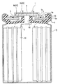
図1は、実施の形態1に係る圧力スイッチ内蔵式密閉型蓄電池の構成を説明するための要部縦断面図であり、この圧力スイッチ内蔵式密閉型蓄電池は、図示のように、電極群10をアルカリ溶液(図示省略)と共に内部に収納した電槽缶(負極)5が素蓋2によって封止されており、その素蓋2の上面に、充電電流を外部に取り出すための電池キャップ(正極)1が、例えば、スポット溶接等により接合されている。その蓋2とガスケット6の肉薄部6fの間には、電池内部圧力の変化に応じて充電電流の継切を行うためのスイッチ機構Sを構成するスイッチ板8を蓋2に対して接離可能に付勢する皿バネ(本発明の弾発部材)4が配設されている。
[Embodiment 1]
FIG. 1 is a longitudinal sectional view of a main part for explaining the configuration of a pressure switch built-in type sealed storage battery according to
図1から明らかな如く、スイッチ機構Sは、電池内部圧力が上昇してガスケットの肉薄部6fが図の上方に向かって撓むことによって動作する。ガスケットの肉薄部6fが図の上方に向かって撓むには、蓋2とガスケットの肉薄部6fの間に少なくとも撓代に相当する間隔を設ける必要がある。本発明によれば、図1に示すように、蓋2とガスケットの肉薄部6fの間に間隔を設けることによって生じたスペースを前記弾発部材4の収納スペースとして活用することによって、弾発部材をキャップ内に配設していた従来電池に比べて、キャップ1の高さを小さくし、キャップ1の高さを低くしただけ電槽の深さを大きくして、極板10の幅(図では高さ)を大きくすることができる。
As apparent from FIG. 1, the switch mechanism S operates when the internal pressure of the battery rises and the
また、蓋2と電池キャップ1を溶接により接合するため、その接合状態が確実なものとなり接合不良の発生を回避することができ、その接合部(本発明の溶接部)3における電気抵抗が少なくなり充電効率が向上する。また、素蓋2と電池キャップ1を予め溶接により一体化しておくことにより、組み立て作業の能率が顕著に向上すると共に、組み付け精度を安定的に向上させることもでき、かつ、塵や埃等の異物が接合面に介在するような不具合を回避することができる。従って、高い封口精度(密封性)を安定に維持することができ、ガス漏れや漏液等の不具合が発生しにくくなる。
Further, since the
全体について詳しく説明すると、電槽缶5の上周縁には、絶縁性素材からなるガスケット6の周縁部を密嵌させるための凹溝部5aが形成されており、下部開放の偏平な有天円筒状に形成された電池キャップ1の下部に外向きに形成されたフランジ部1aを、ガスケット6の内周部6aよりも内側の位置に配設して、そのフランジ部1aを円板状の素蓋2の上に、例えば、スポット溶接等により作業性よく溶接することができる。なお、電池キャップ1の側壁面には、電池内部圧力の変化に応じてガスケット6が無理なく変形できるように、脱気用の孔hが形成されている。
The whole will be described in detail. On the upper peripheral edge of the battery case can 5, a
ガスケット6の内周部6aには係止溝6bが形成され、その係止溝6bに、素蓋2の周縁部のみを係止させている。このように、一枚の板部材(素蓋2)のみを係止溝6bに係止させるので、図7に示す従来の二枚合わせで係止させる場合よりも、電槽缶5を深く形成することができ、充電容量(電池容量)の増大を図ることができる。また、その組み
付け精度が安定するため、高い密封性を確保しやすくなり、その密封性を維持しやすくなる。
A locking
ガスケット6の中央部に形成された円筒状の保持部6cの貫通孔6dには、例えば、円柱状に形成された接続端子9が一体的に嵌装固定され、その下部がリード線7を介して電極群10に接続されている。一方、貫通孔6dから突出した接続端子9の上部には、孔付き円板状のスイッチ板(他方の端子)8が固定されている。その接続端子9の上部とスイッチ板8の上面には絶縁部材を被嵌してスイッチ板8と接続端子9を電池キャップ1に対して絶縁することができる。なお、皿バネ4に代えて、コイルバネや板バネ等を用いてもよい。
In the through
ガスケット6の係止溝6bに係止された素蓋2の中央部には、円形孔(本発明の開口)2aが形成され、その円形孔2aに、ガスケット6の保持部6cが所定の隙間を有して下方から嵌入しており、これにより、電池内部圧力の変化に応じてガスケット6が自在に変形し、そのガスケット6と共に、スイッチ板8の上下方向の変位が許容される。なお、本発明の開口2aは、円形孔に限定されることなく、楕円や方形(矩形、正方形等)等の孔であってもよい。
A circular hole (opening of the present invention) 2a is formed in the central portion of the
また、ガスケット6の上面には、電池内部圧力が急に上昇した場合に、電槽缶5を保護するために、亀裂を発生させやすくするノッチ状の安全弁(本発明の切欠き部)6eが形成されており、充電中に電池内部圧力が急に増大した場合に、安全弁6eからガスケット6に亀裂を生じさせて、電池キャップ1の小孔hからガスを外部に放出させることができ、これにより、電槽缶5を変形させたり破損させたりせずに済み、安全性も向上する。
In addition, on the upper surface of the
充電電流の継切を行うためのスイッチ機構Sは、本実施の形態では、電池キャップ1と素蓋2の間に設けられており、このスイッチ機構Sは、皿バネ4によって付勢される平板状のスイッチ板(本発明の第1端子)8と、平板状の素蓋(本発明の第2端子)2と、からなる。より具体的には、スイッチ板8は、ガスケット6の中央部に貫通して固定状態に貫設された接続端子9の上部に固定され、その接続端子9は変形可能なリード線7を介して電極群10の正極集電板(図示省略)に接続されており、その接続端子9の上端部とスイッチ板8の一部が、前述したように、絶縁部材によって覆われ、その外側の外周縁8bが第1端子となる。一方、素蓋2は、溶接部3よりも内側の部分が円形状に切り抜かれ、その円形孔2aの周縁(本発明の開口縁)2bが第2端子となる。
In this embodiment, the switch mechanism S for switching the charging current is provided between the
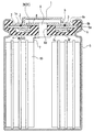
このような構成により、電池内部圧力が低い状態では、図1に示すように、素蓋2の周縁2bにスイッチ板8の外周縁8bが付勢状態に接触してスイッチ機構Sがオンとなり、電池内部圧力が一定圧力以上になると、図2に示すように、ガスケット6が図の上方へ変形することによりスイッチ板8の外周縁8bが素蓋2の周縁2bから離間し、スイッチ機構Sがオフとなり充電電流が切断され、電池内部圧力の変化に連動したパルス充電が行われる。このように、電池内部圧力の変化に応じて充電電流が制御されるため、電池温度の上昇が抑えられ、高い充電効率を得ることができ、急速充電が可能となる。
With such a configuration, when the internal pressure of the battery is low, as shown in FIG. 1, the outer
図1に示す如く、弾発部材4と極板10が近い位置にあり、極板10で発熱がおきると弾発部材4にも熱が伝わり易いが、弾発部材としての皿バネ4を金属材で形成することにより、従来のように、ゴムを用いる場合よりも弾性特性が安定化し、温度上昇の影響を受けることが少なくなり、常に、電池内部圧力の変化に適切に拡縮動作し圧力スイッチ機構Sのオン・オフ動作が安定化し、信頼性が向上する。
As shown in FIG. 1, the
該実施の形態1では、図1および図2に示すように、弾発部材4として適用した皿バネのうち径の小さい一端をガスケットに設けた筒状の保持部6cの外周の下端部に当接させる。該構成によって、図1に示した圧力スイッチがオンの状態においても、また、図2に示したように圧力スイッチがオフの状態においても、筒状の保持部6cに対する皿バネの押圧力によって、保持部6cが蓋2に対して傾くことなく付勢されるので、スイッチ板8と蓋2の接触が良好で両者間の電気抵抗が小さく、且つ、スイッチ板8と蓋2が確実に接離するため、信頼性の高い圧力スイッチ機能を得ることができる。
In the first embodiment, as shown in FIGS. 1 and 2, one end having a small diameter of the disc spring applied as the
〔実施の形態2〕
本実施の形態2では、図3に示すように、実施形態1に於いて弾発部材4として皿バネに替えて円錐形のコイルバネを適用する。該円錐形のコイルバネの場合は、円柱形のコイルバネと異なり、バネを構成する線材が上下方向に重ならないのでバネの高さを小さくできる利点がある。
[Embodiment 2]
In the second embodiment, as shown in FIG. 3, instead of the disc springs apply a conical coil spring as the
該実施の形態2では、図3に示すように、円錐形のコイルバネのうち径の小さい一端をガスケットに設けた筒状の保持部6cの外周の下端部に当接させる。該構成によって、筒状の保持部6cに対するコイルバネの押圧力によって、保持部6cが蓋2に対して傾くことなく付勢されるので、スイッチ板8と蓋2の接触が良好で両者間の電気抵抗が小さく、且つ、スイッチ板8と蓋2が確実に接離するため、信頼性の高い圧力スイッチ機能を得ることができる。
In the second embodiment, as shown in FIG. 3, one end having a small diameter of the conical coil spring is brought into contact with the lower end portion of the outer periphery of the cylindrical holding
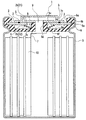
〔実施の形態3〕
本実施の形態3では、図4に示すように、ガスケット6の中央部に形成された円筒状の保持部6dを、素蓋2に形成された開口2aに対して、摺接状態となるように嵌挿させ、封口性を向上させると共に、蓋2の周縁2bに対してスイッチ板8の外周縁8bを平行な状態で接触させることができるようにしている。なお、前実施の形態1と同一又は同等部材については同一符号を付し、その説明を省略している。
[Embodiment 3]
In the third embodiment, as shown in FIG. 4, the
例えば、その保持部6dと開口2aとの間における密封性が確保されうる程度の設計条件で保持部6dの外径と開口2aの内径を設定すれば、封口性が向上しガス漏れや液漏れをより一層効果的に防止することができ、また、接続端子9を保持した保持部6dの上下方向の変位動作が安定化するため、素蓋2に対するスイッチ板8の接触状態が確実となり、高い充電効率を安定して得ることができる。
For example, if the outer diameter of the holding
なお、本実施の形態3では、電池内部圧力が増大した状態は、図2の状態と基本的には同じであり図示を省略している。また、本発明の開口2aは、円形孔に限定されることなく、楕円や方形(矩形、正方形等)等の孔であってもよいのは、前実施の形態1と同じである。
In the third embodiment, the state in which the battery internal pressure is increased is basically the same as the state in FIG. 2 and is not shown. Further, the
(実施例)
幅が45.5mmのニッケル電極を正極とし、幅が45.5mmの水素吸蔵合金電極をセパレータを介して捲回し極板群を構成した。該極板群を適用して、図1に示す構成(キャップ1が蓋2と溶接により接合され、ガスケット6の係止溝6bに素蓋2のみが係止されている)を備え、動作圧力が2.4MPaの圧力スイッチ(S)を内蔵する定格容量1800mAhのAAサイズの圧力スイッチ内蔵式の密閉型ニッケル水素蓄電池を10000個作製した。なお、図1に示した構成とすることにより、後記比較例として記載した従来の蓄電池に比べてキャップならびに圧力スイッチの高さ寸法を小さくし、電極の幅を2.5mm大きくすることが可能となり、従来の蓄電池に比べて約6%容量を大きくすることができた。
(Example)
A nickel electrode having a width of 45.5 mm was used as a positive electrode, and a hydrogen storage alloy electrode having a width of 45.5 mm was wound through a separator to constitute an electrode plate group. Applying the polar plate group, the configuration shown in FIG. 1 (
作製した電池全数を常温常湿の雰囲気に1週間放置した後、目視による外観検査を行い、漏液の有無、組立不良の有無を調査した。目視検査で正常と判定された蓄電池(漏液がなく、正常に組立られた蓄電池)の中からサンプル電池20個を抜き取り、所定の方法にて化成を行った後、化成済みの電池を、周囲温度20℃、充電レート0.1ItAで16時間充電し、同温度で1時間放置した後放電レート0.2ItA、放電カット電圧1.0Vとして放電し、前記定格容量に等しい放電容量が得られることを確認した。次いで、周囲温度20℃、充電電圧1.65Vで15分間定電圧充電を行い、同温度で1時間放置後、放電レート0.2ItA、放電カット電圧1.0Vとして定電流放電をおこなった。該充放電操作を5回繰り返し行い、5回目の放電で得られた放電容量の定格容量に対する比率をもって急速充電における充電受け入れ性能を評価する指標とした。 All the produced batteries were left in a normal temperature and humidity atmosphere for one week, and then a visual appearance inspection was performed to investigate the presence of liquid leakage and assembly failure. After removing 20 sample batteries from a storage battery that has been judged to be normal by visual inspection (a storage battery that has not been leaked and has been assembled normally) and formed by a predetermined method, Charge for 16 hours at a temperature of 20 ° C. and a charge rate of 0.1 ItA, leave for 1 hour at the same temperature, and then discharge at a discharge rate of 0.2 ItA and a discharge cut voltage of 1.0 V to obtain a discharge capacity equal to the rated capacity. It was confirmed. Next, constant voltage charging was performed for 15 minutes at an ambient temperature of 20 ° C. and a charging voltage of 1.65 V. After standing at the same temperature for 1 hour, constant current discharging was performed at a discharge rate of 0.2 ItA and a discharge cut voltage of 1.0 V. This charge / discharge operation was repeated 5 times, and the ratio of the discharge capacity obtained by the fifth discharge to the rated capacity was used as an index for evaluating the charge acceptance performance in the rapid charge.
(比較例)
幅が43mmのニッケル電極を正極とし、幅が43mmの水素吸蔵合金電極をセパレータを介して積層し、該積層体を捲回し捲回式極板群を構成した。該極板群を適用して、図7に示す構成(キャップ21の内部にゴム製の弾発部材4を備え、キャップ21が蓋22に溶接されておらず、キャップ21と素蓋22は、その周縁部で互いに重ね合わされて二枚重ねでガスケット26の係止溝に係止されている)を備え、それ以外は前記実施例と同じ構成を有し、定格容量1700mAhのAAサイズの圧力スイッチ内蔵式密閉型蓄電池10000個を作製した。該電池を、実施例と同様に常温常湿で1週間放置し、全数目視検査により、漏液の有無、組み付け不良の有無を調べた。また、目視による外観検査において正常と判定された電池10個を抜き取り、実施例と同様の試験に供した。
(Comparative example)
A nickel electrode having a width of 43 mm was used as a positive electrode, a hydrogen storage alloy electrode having a width of 43 mm was laminated via a separator, and the laminate was wound to form a wound electrode group. Applying the electrode plate group, the structure shown in FIG. 7 (with the
(目視による外観調査結果)
実施例および比較例の目視による外観調査の結果を表1に示す。

Table 1 shows the results of visual inspection of the examples and comparative examples.
(急速充電試験結果)
前記充電にて行った急速充電試験結果を図5に示す。図5において横軸は、5回目の放電容量{定格容量に対する比率(%)}、縦軸は電池個数である。図5に示すように比較例の密閉型蓄電池は、実施例の密閉型蓄電池に比較して、放電容量がかなり低くなっており、さらに、10セル中2セルの放電容量が極端に低くなっていることが確認された。比較例電池の放電容量が実施例電池に比べて全体的に低いのは、キャップと蓋が接合されていないために、その間の接触抵抗が大きく急速充電時の充電受け入れが低かったためであり、10個中2個の放電容量が極端に低いのは、キャップと蓋の組み付け精度に、目視検査では確認できない程度の軽度の不具合が生じたために、キャップと蓋の間の接触抵抗が極端に大きくなったためと考えられる。
(Quick charge test results)
FIG. 5 shows the result of the quick charge test performed by the above charging. In FIG. 5, the horizontal axis represents the fifth discharge capacity {ratio to the rated capacity (%)}, and the vertical axis represents the number of batteries. As shown in FIG. 5, the sealed storage battery of the comparative example has a considerably lower discharge capacity than the sealed storage battery of the example, and the discharge capacity of 2 cells out of 10 cells is extremely low. It was confirmed that The reason why the discharge capacity of the comparative example battery is generally lower than that of the example battery is that the cap and the lid are not joined, and therefore the contact resistance between them is large and the charge acceptance during rapid charging is low. The reason why the discharge capacity of 2 pieces is extremely low is that the contact resistance between the cap and the lid becomes extremely large because the assembling accuracy of the cap and the lid has a minor problem that cannot be confirmed by visual inspection. It is thought that it was because of.
図6に、前記実施例に係る密閉型ニッケル水素蓄電池を定電圧充電したときの、充電電流および電池温度の時間的推移の1例を示す。図6に示すように充電の鋼板において圧力スイッチが動作し、圧力スイッチが動作している間はパルス常の充電が行われ、電池温度のさらなる上昇が抑制される。ここで示した周囲温度20℃での充電においては、比較例電池においても圧力スイッチが正常に動作したが、例えば周囲温度が30℃を超えるような高温で充電した場合は電池温度がさらに上昇するため、ゴムの弾性が劣化して圧力スイッチが正常に動作せず、圧力スイッチがオンの状態になったままになり、電池温度が異常に上昇する虞がある。 FIG. 6 shows an example of the temporal transition of the charging current and the battery temperature when the sealed nickel-metal hydride storage battery according to the embodiment is charged at a constant voltage. As shown in FIG. 6, the pressure switch is operated in the steel plate for charging, and pulse charging is performed while the pressure switch is operating, and further increase in battery temperature is suppressed. In the charging at the ambient temperature of 20 ° C. shown here, the pressure switch operated normally also in the comparative battery. However, for example, when charging at a high temperature such that the ambient temperature exceeds 30 ° C., the battery temperature further increases. For this reason, the elasticity of the rubber deteriorates, the pressure switch does not operate normally, the pressure switch remains on, and the battery temperature may rise abnormally.
1…電池キャップ、1a…外向きフランジ、2…素蓋、2b…開口縁、3…溶接部、4…弾発部材、5…電槽缶、6…ガスケット、6a…内周部、6b…係止溝、6c…保持部、6e…切欠き部、6f…肉薄部、8…スイッチ板、8b…外周縁、9…接続端子、10…電極群、S…スイッチ機構、S1…第1端子、S2…第2端子、h…小孔
DESCRIPTION OF
Claims (2)
、ガスケット(6)およびガスケット(6)の透孔(6d)に嵌着した接続端子(9)によって封止され、該蓋(2)に、正極端子または負極端子を兼ねるキャップ(1)が載設され、かつ、電池内部圧力の変化に応じて拡縮動作する弾発部材を備えたスイッチ機構(S)によって充電電流の継切を行うようにした密閉型蓄電池において、前記弾発部材(4)が、前記蓋(2)の内面とガスケット(6)の肉薄部(6f)の間に配設されたこと、前記接続端子(9)の上部に固定されたスイッチ板と前記蓋(2)とは互いに接触していること、および、電池内部圧力が一定圧力以上になると前記弾発部材が収縮して前記ガスケット(6)が変形することにより前記スイッチ板と前記蓋(2)とが離間することを特徴とする密閉型蓄電池。 The battery case (5) containing the electrode group (10) together with the alkaline solution is a metal lid (2)
The cap (1) serving as a positive electrode terminal or a negative electrode terminal is mounted on the lid (2) by sealing the gasket (6) and the connection terminal (9) fitted in the through hole (6d) of the gasket (6). In the sealed storage battery, the charging member (4), wherein the charging current is cut off by a switch mechanism (S) provided with a resilient member that expands and contracts in response to a change in the internal pressure of the battery. Is disposed between the inner surface of the lid (2) and the thin part (6f) of the gasket (6), the switch plate fixed to the upper part of the connection terminal (9), and the lid (2). Are in contact with each other, and when the internal pressure of the battery exceeds a certain level, the elastic member contracts and the gasket (6) is deformed to separate the switch plate and the lid (2). A sealed storage battery characterized by that .
Priority Applications (1)
| Application Number | Priority Date | Filing Date | Title |
|---|---|---|---|
| JP2003430996A JP4678128B2 (en) | 2003-12-25 | 2003-12-25 | Sealed storage battery |
Applications Claiming Priority (1)
| Application Number | Priority Date | Filing Date | Title |
|---|---|---|---|
| JP2003430996A JP4678128B2 (en) | 2003-12-25 | 2003-12-25 | Sealed storage battery |
Publications (3)
| Publication Number | Publication Date |
|---|---|
| JP2005190836A JP2005190836A (en) | 2005-07-14 |
| JP2005190836A5 JP2005190836A5 (en) | 2007-02-15 |
| JP4678128B2 true JP4678128B2 (en) | 2011-04-27 |
Family
ID=34789201
Family Applications (1)
| Application Number | Title | Priority Date | Filing Date |
|---|---|---|---|
| JP2003430996A Expired - Fee Related JP4678128B2 (en) | 2003-12-25 | 2003-12-25 | Sealed storage battery |
Country Status (1)
| Country | Link |
|---|---|
| JP (1) | JP4678128B2 (en) |
Families Citing this family (1)
| Publication number | Priority date | Publication date | Assignee | Title |
|---|---|---|---|---|
| KR20080072443A (en) * | 2007-02-02 | 2008-08-06 | 삼성에스디아이 주식회사 | Fixing cap by welding and cell module equipped it |
Citations (1)
| Publication number | Priority date | Publication date | Assignee | Title |
|---|---|---|---|---|
| JP2001135301A (en) * | 1999-10-27 | 2001-05-18 | Samsung Sdi Co Ltd | Sealed battery |
Family Cites Families (5)
| Publication number | Priority date | Publication date | Assignee | Title |
|---|---|---|---|---|
| JPS5933751A (en) * | 1982-08-17 | 1984-02-23 | Hitachi Maxell Ltd | Cylindrical alkaline battery |
| JPS625564U (en) * | 1985-06-26 | 1987-01-13 | ||
| JPH10334873A (en) * | 1997-05-30 | 1998-12-18 | Shin Kobe Electric Mach Co Ltd | Sealed battery |
| JP3056457B2 (en) * | 1997-12-16 | 2000-06-26 | 富士電気化学株式会社 | Sealed secondary battery |
| JP3331946B2 (en) * | 1998-02-06 | 2002-10-07 | エフ・ディ−・ケイ株式会社 | Current interrupting element and battery having current interrupting element |
-
2003
- 2003-12-25 JP JP2003430996A patent/JP4678128B2/en not_active Expired - Fee Related
Patent Citations (1)
| Publication number | Priority date | Publication date | Assignee | Title |
|---|---|---|---|---|
| JP2001135301A (en) * | 1999-10-27 | 2001-05-18 | Samsung Sdi Co Ltd | Sealed battery |
Also Published As
| Publication number | Publication date |
|---|---|
| JP2005190836A (en) | 2005-07-14 |
Similar Documents
| Publication | Publication Date | Title |
|---|---|---|
| KR101514827B1 (en) | Secondary battery and method for manufacturing the same | |
| CN1145230C (en) | Current interrupter for electrochemical cells | |
| JP5011664B2 (en) | Sealed secondary battery | |
| JP4515371B2 (en) | Cylindrical lithium ion battery and manufacturing method thereof | |
| KR101310015B1 (en) | Sealed battery | |
| KR102487217B1 (en) | Cap Assembly Having Rivet, and Cylindrical Battery Comprising Beading-part free and Climping-part free and the Cap Assembly | |
| CN107112473B (en) | Battery with a battery cell | |
| KR101706382B1 (en) | Galvanic element for high stresses | |
| US11189880B2 (en) | Feed-through forming a terminal for a metal-ion electrochemical accumulator, integrating a gas relief valve, associated accumulator | |
| US6703158B1 (en) | Cylindrical storage battery | |
| JP5783138B2 (en) | Current interrupt device and power storage device including the same | |
| EP2485292B1 (en) | Secondary battery | |
| JPH06140011A (en) | Explosion-proof sealed battery | |
| JP2009289695A (en) | Flat battery | |
| KR101446153B1 (en) | Cap assembly for secondary battery, secondary battery using the same, and method for manufacturing the secondary battery | |
| JP4678128B2 (en) | Sealed storage battery | |
| JP2005190837A (en) | Sealed storage battery | |
| JP2017162563A (en) | Secondary battery and secondary battery assembly | |
| KR101453782B1 (en) | Secondary battery and method for manufacturing the same | |
| JP4617671B2 (en) | Sealed storage battery | |
| JP6880452B2 (en) | Sealed battery | |
| KR102489229B1 (en) | Cylindrical Battery Having no Beading Part and Method For Manufacturing Thereof | |
| KR20060037844A (en) | Cylindrical li secondary battery | |
| KR101279408B1 (en) | Method for manufacturing secondary battery | |
| JP4867118B2 (en) | battery |
Legal Events
| Date | Code | Title | Description |
|---|---|---|---|
| A711 | Notification of change in applicant |
Free format text: JAPANESE INTERMEDIATE CODE: A712 Effective date: 20060404 |
|
| A521 | Request for written amendment filed |
Free format text: JAPANESE INTERMEDIATE CODE: A523 Effective date: 20061221 |
|
| A621 | Written request for application examination |
Free format text: JAPANESE INTERMEDIATE CODE: A621 Effective date: 20061221 |
|
| A711 | Notification of change in applicant |
Free format text: JAPANESE INTERMEDIATE CODE: A711 Effective date: 20080220 |
|
| A977 | Report on retrieval |
Free format text: JAPANESE INTERMEDIATE CODE: A971007 Effective date: 20100226 |
|
| A711 | Notification of change in applicant |
Free format text: JAPANESE INTERMEDIATE CODE: A712 Effective date: 20100507 |
|
| A131 | Notification of reasons for refusal |
Free format text: JAPANESE INTERMEDIATE CODE: A131 Effective date: 20100622 |
|
| A521 | Request for written amendment filed |
Free format text: JAPANESE INTERMEDIATE CODE: A523 Effective date: 20100819 |
|
| TRDD | Decision of grant or rejection written | ||
| A01 | Written decision to grant a patent or to grant a registration (utility model) |
Free format text: JAPANESE INTERMEDIATE CODE: A01 Effective date: 20110105 |
|
| A01 | Written decision to grant a patent or to grant a registration (utility model) |
Free format text: JAPANESE INTERMEDIATE CODE: A01 |
|
| A61 | First payment of annual fees (during grant procedure) |
Free format text: JAPANESE INTERMEDIATE CODE: A61 Effective date: 20110118 |
|
| R150 | Certificate of patent or registration of utility model |
Free format text: JAPANESE INTERMEDIATE CODE: R150 |
|
| FPAY | Renewal fee payment (event date is renewal date of database) |
Free format text: PAYMENT UNTIL: 20140210 Year of fee payment: 3 |
|
| LAPS | Cancellation because of no payment of annual fees |