JP4674024B2 - Gear shift device - Google Patents
Gear shift device Download PDFInfo
- Publication number
- JP4674024B2 JP4674024B2 JP2001534961A JP2001534961A JP4674024B2 JP 4674024 B2 JP4674024 B2 JP 4674024B2 JP 2001534961 A JP2001534961 A JP 2001534961A JP 2001534961 A JP2001534961 A JP 2001534961A JP 4674024 B2 JP4674024 B2 JP 4674024B2
- Authority
- JP
- Japan
- Prior art keywords
- gear
- fluid pressure
- gear shift
- sensor
- computer
- Prior art date
- Legal status (The legal status is an assumption and is not a legal conclusion. Google has not performed a legal analysis and makes no representation as to the accuracy of the status listed.)
- Expired - Fee Related
Links
- 239000012530 fluid Substances 0.000 claims description 42
- 238000012790 confirmation Methods 0.000 claims description 5
- 230000002093 peripheral effect Effects 0.000 description 5
- 230000007935 neutral effect Effects 0.000 description 4
- 230000006835 compression Effects 0.000 description 1
- 238000007906 compression Methods 0.000 description 1
- 238000001514 detection method Methods 0.000 description 1
- 238000010586 diagram Methods 0.000 description 1
- 230000005611 electricity Effects 0.000 description 1
- 239000000446 fuel Substances 0.000 description 1
- 238000004519 manufacturing process Methods 0.000 description 1
- 230000001360 synchronised effect Effects 0.000 description 1
Images
Classifications
-
- B—PERFORMING OPERATIONS; TRANSPORTING
- B60—VEHICLES IN GENERAL
- B60W—CONJOINT CONTROL OF VEHICLE SUB-UNITS OF DIFFERENT TYPE OR DIFFERENT FUNCTION; CONTROL SYSTEMS SPECIALLY ADAPTED FOR HYBRID VEHICLES; ROAD VEHICLE DRIVE CONTROL SYSTEMS FOR PURPOSES NOT RELATED TO THE CONTROL OF A PARTICULAR SUB-UNIT
- B60W30/00—Purposes of road vehicle drive control systems not related to the control of a particular sub-unit, e.g. of systems using conjoint control of vehicle sub-units
- B60W30/18—Propelling the vehicle
-
- B—PERFORMING OPERATIONS; TRANSPORTING
- B60—VEHICLES IN GENERAL
- B60W—CONJOINT CONTROL OF VEHICLE SUB-UNITS OF DIFFERENT TYPE OR DIFFERENT FUNCTION; CONTROL SYSTEMS SPECIALLY ADAPTED FOR HYBRID VEHICLES; ROAD VEHICLE DRIVE CONTROL SYSTEMS FOR PURPOSES NOT RELATED TO THE CONTROL OF A PARTICULAR SUB-UNIT
- B60W10/00—Conjoint control of vehicle sub-units of different type or different function
- B60W10/04—Conjoint control of vehicle sub-units of different type or different function including control of propulsion units
-
- B—PERFORMING OPERATIONS; TRANSPORTING
- B60—VEHICLES IN GENERAL
- B60W—CONJOINT CONTROL OF VEHICLE SUB-UNITS OF DIFFERENT TYPE OR DIFFERENT FUNCTION; CONTROL SYSTEMS SPECIALLY ADAPTED FOR HYBRID VEHICLES; ROAD VEHICLE DRIVE CONTROL SYSTEMS FOR PURPOSES NOT RELATED TO THE CONTROL OF A PARTICULAR SUB-UNIT
- B60W10/00—Conjoint control of vehicle sub-units of different type or different function
- B60W10/10—Conjoint control of vehicle sub-units of different type or different function including control of change-speed gearings
-
- B—PERFORMING OPERATIONS; TRANSPORTING
- B60—VEHICLES IN GENERAL
- B60W—CONJOINT CONTROL OF VEHICLE SUB-UNITS OF DIFFERENT TYPE OR DIFFERENT FUNCTION; CONTROL SYSTEMS SPECIALLY ADAPTED FOR HYBRID VEHICLES; ROAD VEHICLE DRIVE CONTROL SYSTEMS FOR PURPOSES NOT RELATED TO THE CONTROL OF A PARTICULAR SUB-UNIT
- B60W30/00—Purposes of road vehicle drive control systems not related to the control of a particular sub-unit, e.g. of systems using conjoint control of vehicle sub-units
- B60W30/18—Propelling the vehicle
- B60W30/1819—Propulsion control with control means using analogue circuits, relays or mechanical links
-
- B—PERFORMING OPERATIONS; TRANSPORTING
- B60—VEHICLES IN GENERAL
- B60W—CONJOINT CONTROL OF VEHICLE SUB-UNITS OF DIFFERENT TYPE OR DIFFERENT FUNCTION; CONTROL SYSTEMS SPECIALLY ADAPTED FOR HYBRID VEHICLES; ROAD VEHICLE DRIVE CONTROL SYSTEMS FOR PURPOSES NOT RELATED TO THE CONTROL OF A PARTICULAR SUB-UNIT
- B60W2510/00—Input parameters relating to a particular sub-units
- B60W2510/06—Combustion engines, Gas turbines
- B60W2510/0657—Engine torque
-
- B—PERFORMING OPERATIONS; TRANSPORTING
- B60—VEHICLES IN GENERAL
- B60W—CONJOINT CONTROL OF VEHICLE SUB-UNITS OF DIFFERENT TYPE OR DIFFERENT FUNCTION; CONTROL SYSTEMS SPECIALLY ADAPTED FOR HYBRID VEHICLES; ROAD VEHICLE DRIVE CONTROL SYSTEMS FOR PURPOSES NOT RELATED TO THE CONTROL OF A PARTICULAR SUB-UNIT
- B60W2510/00—Input parameters relating to a particular sub-units
- B60W2510/10—Change speed gearings
- B60W2510/1015—Input shaft speed, e.g. turbine speed
-
- B—PERFORMING OPERATIONS; TRANSPORTING
- B60—VEHICLES IN GENERAL
- B60W—CONJOINT CONTROL OF VEHICLE SUB-UNITS OF DIFFERENT TYPE OR DIFFERENT FUNCTION; CONTROL SYSTEMS SPECIALLY ADAPTED FOR HYBRID VEHICLES; ROAD VEHICLE DRIVE CONTROL SYSTEMS FOR PURPOSES NOT RELATED TO THE CONTROL OF A PARTICULAR SUB-UNIT
- B60W2510/00—Input parameters relating to a particular sub-units
- B60W2510/10—Change speed gearings
- B60W2510/104—Output speed
-
- F—MECHANICAL ENGINEERING; LIGHTING; HEATING; WEAPONS; BLASTING
- F16—ENGINEERING ELEMENTS AND UNITS; GENERAL MEASURES FOR PRODUCING AND MAINTAINING EFFECTIVE FUNCTIONING OF MACHINES OR INSTALLATIONS; THERMAL INSULATION IN GENERAL
- F16H—GEARING
- F16H59/00—Control inputs to control units of change-speed-, or reversing-gearings for conveying rotary motion
- F16H59/68—Inputs being a function of gearing status
- F16H2059/6807—Status of gear-change operation, e.g. clutch fully engaged
-
- F—MECHANICAL ENGINEERING; LIGHTING; HEATING; WEAPONS; BLASTING
- F16—ENGINEERING ELEMENTS AND UNITS; GENERAL MEASURES FOR PRODUCING AND MAINTAINING EFFECTIVE FUNCTIONING OF MACHINES OR INSTALLATIONS; THERMAL INSULATION IN GENERAL
- F16H—GEARING
- F16H59/00—Control inputs to control units of change-speed-, or reversing-gearings for conveying rotary motion
- F16H59/36—Inputs being a function of speed
- F16H59/38—Inputs being a function of speed of gearing elements
- F16H59/40—Output shaft speed
-
- F—MECHANICAL ENGINEERING; LIGHTING; HEATING; WEAPONS; BLASTING
- F16—ENGINEERING ELEMENTS AND UNITS; GENERAL MEASURES FOR PRODUCING AND MAINTAINING EFFECTIVE FUNCTIONING OF MACHINES OR INSTALLATIONS; THERMAL INSULATION IN GENERAL
- F16H—GEARING
- F16H59/00—Control inputs to control units of change-speed-, or reversing-gearings for conveying rotary motion
- F16H59/36—Inputs being a function of speed
- F16H59/38—Inputs being a function of speed of gearing elements
- F16H59/42—Input shaft speed
-
- F—MECHANICAL ENGINEERING; LIGHTING; HEATING; WEAPONS; BLASTING
- F16—ENGINEERING ELEMENTS AND UNITS; GENERAL MEASURES FOR PRODUCING AND MAINTAINING EFFECTIVE FUNCTIONING OF MACHINES OR INSTALLATIONS; THERMAL INSULATION IN GENERAL
- F16H—GEARING
- F16H61/00—Control functions within control units of change-speed- or reversing-gearings for conveying rotary motion ; Control of exclusively fluid gearing, friction gearing, gearings with endless flexible members or other particular types of gearing
- F16H61/26—Generation or transmission of movements for final actuating mechanisms
- F16H61/28—Generation or transmission of movements for final actuating mechanisms with at least one movement of the final actuating mechanism being caused by a non-mechanical force, e.g. power-assisted
- F16H61/30—Hydraulic or pneumatic motors or related fluid control means therefor
-
- F—MECHANICAL ENGINEERING; LIGHTING; HEATING; WEAPONS; BLASTING
- F16—ENGINEERING ELEMENTS AND UNITS; GENERAL MEASURES FOR PRODUCING AND MAINTAINING EFFECTIVE FUNCTIONING OF MACHINES OR INSTALLATIONS; THERMAL INSULATION IN GENERAL
- F16H—GEARING
- F16H63/00—Control outputs from the control unit to change-speed- or reversing-gearings for conveying rotary motion or to other devices than the final output mechanism
- F16H63/40—Control outputs from the control unit to change-speed- or reversing-gearings for conveying rotary motion or to other devices than the final output mechanism comprising signals other than signals for actuating the final output mechanisms
- F16H63/50—Signals to an engine or motor
- F16H63/502—Signals to an engine or motor for smoothing gear shifts
-
- Y—GENERAL TAGGING OF NEW TECHNOLOGICAL DEVELOPMENTS; GENERAL TAGGING OF CROSS-SECTIONAL TECHNOLOGIES SPANNING OVER SEVERAL SECTIONS OF THE IPC; TECHNICAL SUBJECTS COVERED BY FORMER USPC CROSS-REFERENCE ART COLLECTIONS [XRACs] AND DIGESTS
- Y10—TECHNICAL SUBJECTS COVERED BY FORMER USPC
- Y10T—TECHNICAL SUBJECTS COVERED BY FORMER US CLASSIFICATION
- Y10T74/00—Machine element or mechanism
- Y10T74/19—Gearing
- Y10T74/19219—Interchangeably locked
- Y10T74/19251—Control mechanism
-
- Y—GENERAL TAGGING OF NEW TECHNOLOGICAL DEVELOPMENTS; GENERAL TAGGING OF CROSS-SECTIONAL TECHNOLOGIES SPANNING OVER SEVERAL SECTIONS OF THE IPC; TECHNICAL SUBJECTS COVERED BY FORMER USPC CROSS-REFERENCE ART COLLECTIONS [XRACs] AND DIGESTS
- Y10—TECHNICAL SUBJECTS COVERED BY FORMER USPC
- Y10T—TECHNICAL SUBJECTS COVERED BY FORMER US CLASSIFICATION
- Y10T74/00—Machine element or mechanism
- Y10T74/20—Control lever and linkage systems
- Y10T74/20012—Multiple controlled elements
- Y10T74/20018—Transmission control
Landscapes
- Engineering & Computer Science (AREA)
- Chemical & Material Sciences (AREA)
- Combustion & Propulsion (AREA)
- Transportation (AREA)
- Mechanical Engineering (AREA)
- Automation & Control Theory (AREA)
- Control Of Transmission Device (AREA)
- Gear-Shifting Mechanisms (AREA)
- Seal Device For Vehicle (AREA)
- Massaging Devices (AREA)
Description
【0001】
【発明の属する技術分野】
本発明は請求項1の導入部に示す如き車両用のギヤシフト装置に関する。
【0002】
【従来の技術】
この種のギヤシフト装置は、アメリカ特許第4,593,580号から公知である。駆動ギヤホイールが第1の従動歯車ホイールに噛合しており、この従動ギヤホイールとの噛合から外れて第2の従動歯車ホイールと噛合する必要がある場合、駆動軸のトルクが最初にゼロに減らされてから駆動ギヤホイールが第1の従動ギヤホイールとの噛合から外される。次いで、調整装置により駆動軸と第2従動ギヤホイールの周速を等しくすることによって駆動軸の回転数を第2従動ギヤホイールの回転数に一致させてから駆動ギヤホイールと後者を噛合させる。
【0003】
【発明が解決しようとする課題】
斯かる一致を達成するためのギヤチェンジ時に、エンジン出力や車両速度ひいては従動ギヤホイールの回転数が比較的急速に変えられることで駆動ギヤホイールの回転数又は第2従動ギヤホイールの回転数、又はこれらギヤーホイール両方の回転数が変化するので、ギヤシフト可能な合間が非常に小さいことがあり得る。ギヤシフト達成のため車両の運転者はギヤレバーに力を働かせ続けるので、即ち、ギヤホイールを噛合させようと試みるので、ギヤチェンジが起き得る程にギヤホイールの回転数が一致するまでに、ギヤホイール相互の連続した滑りまたは擦れが容易に生じ得る。又、回転数が完全に一致する前にギヤホイールが噛合すれば、歯の破損が生じ得る。
【0004】
手動操作のギヤボックスでは、噛合時に、スレーブシリンダにより動かされるギヤホイールの移動速度は、ギヤレバーに働く力の関数である。従って、上記の合間にギヤシフト操作がなされ得ないかもしれず、ギヤホイールが相互に滑る又は擦れ合い得る。
【0005】
例えば、この力が大きいと、ギヤシフトは過剰に急速に行われ得る。他方、力が小さいと、上記した合間ではギヤシフト操作が開始・終了しないという結果になり得る。
【0006】
複動流体圧シリンダを備えた流体圧ギヤシフト装置は、本出願人のノルウェー特許第171426号から公知である。
【0007】
本発明の目的は、上記した不具合を被ることがはるかに少ない、導入部で言及した種類のギヤシフト装置を提供することである。
【0008】
【課題を解決するための手段】
本発明の特徴は、請求項に示した特徴節の特徴から明らかであろう。
【0009】
【発明の実施の形態】
図面に関し、本発明を更に詳細に説明する。
【0010】
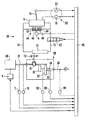
図示しているように、本発明の装置は、複動流体圧マスタシリンダ11、複動流体圧スレーブシリンダ12及びこれらのシリンダを相互接続する2つの流体圧ライン13,14を備えた流体圧ギヤシフト装置10で構成される。
【0011】
しかしながら、シリンダは単動にして、戻しばねで構成してもよいと理解され、その場合に、単に1つのラインがシリンダ間を延びる。
【0012】
マスタシリンダはセレクタ装置、例えばギヤレバー15によって操作でき、スレーブシリンダ12はそのピストンに接続した操作アーム16を有することができ、アームは双頭矢印で示すように例えば前後に動くことができる。
【0013】
ギヤシフト装置を備えた車両は、駆動軸21を備えたエンジン20で構成される。駆動軸の端部がギヤボックス30内に延び、この端部に駆動ギヤホイール31が回転不能に接続される。しかしながら、駆動ギヤホイールは、例えば、操作アーム6により駆動軸に沿って可動である。
【0014】
ギヤボックスには径の異なる複数の従動ギヤホイールが据付けられる。図では第1及び第2従動ギヤホイール32,33のみを示している。従動ギヤホイール32,33と各々共回りするようになっている第1及び第2従動ギヤホイール軸34,35はギヤボックス30内に回転可能に取付られ、ギヤボックスから延びる出力軸36に接続されている。この出力軸36は、車両の駆動ホイール(図示せず)に接続されている。
【0015】
駆動ギヤホイール31をスレーブシリンダの操作アーム16により駆動軸21に沿って動かすと、駆動ギヤホイール31ひいてはエンジンの駆動軸21は従動ギヤホイール32,33のいずれかに接続できる。このように様々な従動ギヤホイールとの噛合で、一定のエンジン出力及び一定の駆動軸21回転数時に種々のトルクを働かせるという目的を達成できる。
【0016】
本発明のギヤシフト装置は、コンピュータ40で構成される。
【0017】
コンピュータの接続先は
ギヤシフト操作・センサ装置S0であり、それを構成するギヤシフト操作開始表示装置S1は、例えば複動マスタシリンダ11のシリンダ室(図示せず)の作動流体圧検出センサであり、セレクタ装置、即ちギヤレバー15により開始されるギヤシフト操作の発生を確認(establish)するよう構成されている。若しくは、ギヤシフト操作・センサ装置は各流体圧ラインの流体圧を確認する2つの圧力センサからなっていて良い。ギヤシフト操作・センサ装置S0は更に、シフトをしなければならないギヤを示すインパルスを送るセレクタ装置又はセンサS2で構成することができる。
【0018】
コンピュータ40の更なる接続先は、
エンジン出力を制御する出力制御装置P、
入力軸に働くトルクの値を確認するトルク確認装置T、及び
駆動軸21及び従動ギヤホイール32,33各々の軸34,35の回転数の値を確認する回転数センサR1、R2、R3である。
【0019】
トルク確認装置Tを、たとえば、駆動軸のトルクに相当するインパルスをコンピュータに送るよう構成された電気抵抗ひずみゲージ等のセンサで構成できる。或いは、この装置を、例えば車両速度と共にエンジン温度と単位時間当たりの燃料消費の値を検出し、相当するインパルスをコンピュータに送るセンサ(図示せず)で構成することもできる。これらのインパルスにより、コンピュータは駆動軸21に働くトルクの値を計算する。
【0020】
回転数センサR2,R3の代わりに、回転数センサR4を設けて従動軸36の回転数を確認し、従動ギヤホイールの軸34,35は出力軸36に常に接続しそれに対し固定のギヤ比で回転してもよい。従って、回転数センサR4は、従動ギヤホイールの回転数に比例した回転数を検出する。そのようなギヤ比をコンピュータに入れることができる。
【0021】
コンピュータは、
ギヤシフト操作・センサ装置S0、トルク確認装置T及び回転数センサR1、R2、R3(場合によってはR4)からインパルスを受取り、
以下で更に詳細に説明する仕方で出力制御装置Pにインパルスを送るよう構成されている。
【0022】
流体圧ラインのうちの1つ(たとえばライン13)に挿入される2位置遮断弁42は、作動流体が流体圧ラインに流入できる第1開位置と、この流体のこのラインへの流入を妨げる第2位置とを任意に選ぶことができる。この遮断弁は、電気的に操作されるものでよく、コンピュータによって同様に制御される。
【0023】
更に、流体圧ライン13、14が複動流体圧アキュームレータ(蓄圧器)44に接続される。ライン13に接続される流体圧アキュームレータ44の側は、遮断弁42とマスタシリンダ11との間の部分に位置した部分に接続される。流体圧アキュームレータをシリンダ部46で構成し、自由に可動なピストン48を取付られて2つのシリンダ空間を限定し、それらの各々に圧縮ばね52,54を取付けることができる。これらのばね52,54はピストン48をシリンダ部の中央に置こうとする。位置センサAはシリンダ部46内のピストン位置を確認し、この位置に関しアキュームレータのチャージ割合を示すインパルスをコンピュータ40に送るよう構成されている。
【0024】
本発明によるギヤシフト装置の作動は下記の通りである。
【0025】
初期段階では、従動ギヤホイール、例えば回転数センサR2に接続されたギヤホイール32が駆動ギヤホイール31に噛合し、遮断弁42が開である、と想定すべきである。ギヤシフトが必要ならば、例えば回転数センサR3に接続された従動ギヤホイール33を駆動ギヤホイール31に噛合させねばならないなら、ギヤレバーをニュートラルポジションへ動かすことが最初試みられる。
【0026】
ギヤレバーのこの動きによりマスタシリンダ11の1シリンダ室の作動流体圧力が増加する。圧力センサS1は直ちにこの圧力増加を確認し、対応するインパルスをコンピュータ40に送る。
【0027】
このギヤシフト操作の途中で運転者が力を減らさず、かくして駆動軸のトルクをほぼゼロに減らすと、コンピュータ40が遮断弁42の閉止を行い、出力装置Pにインパルスを送ることができ、その結果、斯かるエンジン出力の減少を行なう。しかしながら、車両の運転者がギヤレバーに絶え間なく働かせる力により、流体圧アキュームレータ44のチャージも引起こされ、それにより有利にもギヤレバー15を動かすことができ、かくして運転者にはギヤを操作しているという満足感が与えられる。
【0028】
遮断弁が閉じられて駆動軸21のトルクがほぼゼロに減らされると、コンピュータ40は遮断弁42の開を引起こし、アキュームレータ44がスレーブシリンダ12に流体を急速供給する。供給し得る量が多いので、スレーブシリンダのピストンひいては駆動ギヤホイールが急速に動かされる結果、駆動ギヤホイールがニュートラルポジションへと急速に動かされて、いずれの従動ギヤホイールとも噛合しなくなる。例えば、位置センサ(図示せず)が斯かるニュートラルポジションを検出し、対応するインパルスをコンピュータに送ることができる。
【0029】
次いで、ギヤレバーが先に進んでニュートラルポジジョンを通過すると、ギヤセレクタセンサS2が所望のギヤを検出する。このセンサは例えばギヤボックス内に取付られる。
【0030】
次いで、遮断弁42が再び閉じられ、コンピュータ40が駆動ギヤホイール31及び駆動ギヤホイール31を接続すべきギヤホイール33の回転数を比較する。
【0031】
これらの回転数が、これらのギヤホイールの周速が一致するか許容できる速度差範囲内となるよう、合致しているならば、遮断弁が開けられ、ギヤレバーはこれらの歯車を噛合させる最終位置へと移動できる。
【0032】
駆動ギヤホイール21の回転数が低すぎるならば、遮断弁42は閉のままであり、コンピュータ40がインパルスを出力装置Pに送り、エンジンひいては駆動ギヤホイールの回転数を増加させることができる。
【0033】
駆動ギヤホイール21の回転数が高すぎるならば、出力装置Pはエンジンの回転数を減らすよう制御される。
【0034】
駆動ギヤホイール21の周速と所望の従動ギヤホイール33の周速とが互いに十分に近づいて、駆動ギヤホイール21を所望の従動ギヤホイール33に噛合させることができたら、両ギヤホイールの回転数をこの結果変更できるという了解で遮断弁42は開けられ、従って、流体圧アキュームレータ44は多量の作動流体を急速にライン14に送給することによりギヤホイール31,33を可能な最少時間内の間に、即ち、ギヤホイールの回転数がそれらの周速が一定の差範囲内にあるような回転数である間に確実に噛合させることができ、従って、相いに歯が許容できないほど滑ったり擦れたりすることなくギヤホイール31,33を噛合させることができる。
【0035】
ギヤチェンジ完了後、出力装置Pはコンピュータから、選択されたアクセルペダル位置即ち出力値に相当する出力増加に関する情報を与えられる。
【0036】
それにより、噛合し合わねばならないギヤボックスのギヤホイールが互いに合致する回転数を得ることを確保することによって、遮断弁42はギヤシフトを確実なものとし、従って、ギヤホイールの歯が滑ったり欠損したりすることが防がれる。
【0037】
流体圧アキュームレータが保証するのは、ギヤ入れ時にギヤレバーを充分に滑らかに動かすことができ、たとえライン13,14の流体流が一時的に止まってもギヤ入れがほぼ連続的に行われているという感覚を車両の運転者に持たせられること、及び、ギヤ入れ時に噛合させるべきギヤボックスのギヤホイールの回転数が騒音・損傷なしにギヤ入れを起こせる限度内なら、急速操作のために多量の流体をスレーブシリンダへと送給することである。
【0038】
上記ではギヤボックスの単純化した実施の形態を記述した。ギヤボックスを他の仕方で設計してもよいことが理解される。例えば、各ギヤ用の複数の従動ギヤホイールで構成してもよい。更に又、駆動軸を歯付きの軸にして、従動ギヤホイールが噛合できる駆動ギヤホイールを形成してもよい。
【0039】
上記した遮断弁設置の利点に加え、遮断弁は車両前進の際に不注意により逆のギヤにシフトしてしまうのを防ぐこともできる。更に、噛合されるギヤに隣接したギヤでないギヤ、例えば低すぎるギヤ、へと不注意によりシフトしてエンジンを損害させるのを防ぐことができる。
【0040】
本発明によるギヤシフト装置は上記では同期装置なしのギヤボックスについて記述しているが、同期制御装置を備えたギヤボックスについても、これが例えば製造時の何らかの技術的な理由やギヤチェンジ時に車両の運転者が大きな力を働かせる必要のない同期されたギヤボックスを得るために望ましいならば、用いることができると理解される。
【0041】
ギヤシフト装置が流体圧を用いるものであると述べたが、代わりに例えば電気を用いるものであってもよいと理解される。この場合、流体圧のマスタシリンダとスレーブシリンダは電気トランスミッタ装置又はスレーブ装置に替えられる。流体圧の遮断弁42は、流体圧ギヤシフト装置と同様にスレーブ装置の作動を防ぐ電気装置に替えられる。
【図面の簡単な説明】
【図1】 本発明のギヤシフト装置の概略接続図であり、装置構成要素の相互接続を示す。[0001]
BACKGROUND OF THE INVENTION
The present invention relates to a vehicle gear shift device as shown in the introduction portion of
[0002]
[Prior art]
A gear shift device of this kind is known from U.S. Pat. No. 4,593,580. When the drive gear wheel is engaged with the first driven gear wheel and needs to be engaged with the second driven gear wheel out of engagement with the driven gear wheel, the torque on the drive shaft is first reduced to zero. Then, the drive gear wheel is disengaged from the first driven gear wheel. Subsequently, the rotational speed of the drive shaft is matched with the rotation speed of the second driven gear wheel by equalizing the peripheral speeds of the drive shaft and the second driven gear wheel by the adjusting device, and then the drive gear wheel and the latter are meshed.
[0003]
[Problems to be solved by the invention]
At the time of a gear change to achieve such coincidence, the engine output, the vehicle speed, and thus the rotational speed of the driven gear wheel are changed relatively rapidly, so that the rotational speed of the driving gear wheel or the rotational speed of the second driven gear wheel, or Since the rotational speeds of both of these gear wheels change, the interval between gear shifts can be very small. Since the vehicle driver continues to apply force to the gear lever to achieve the gear shift, i.e., it tries to engage the gear wheel, the gear wheel mutual speed is not reached until the gear wheel rotation speed is matched to the extent that a gear change can occur. Continuous sliding or rubbing can easily occur. Also, if the gear wheel meshes before the rotational speeds completely coincide, tooth damage can occur.
[0004]
In a manually operated gear box, the speed of movement of the gear wheel moved by the slave cylinder at the time of meshing is a function of the force acting on the gear lever. Therefore, a gear shift operation may not be performed between the above intervals, and the gear wheels may slide or rub against each other.
[0005]
For example, if this force is large, the gear shift can occur too quickly. On the other hand, if the force is small, the gear shift operation may not start or end between the above intervals.
[0006]
A fluid pressure gearshift device with a double-acting fluid pressure cylinder is known from the applicant's Norwegian patent 171426.
[0007]
The object of the present invention is to provide a gearshift device of the kind mentioned in the introduction, which is far less susceptible to the disadvantages described above.
[0008]
[Means for Solving the Problems]
The features of the invention will be apparent from the features of the features section set forth in the claims.
[0009]
DETAILED DESCRIPTION OF THE INVENTION
The invention is explained in more detail with reference to the drawings.
[0010]
As shown, the apparatus of the present invention comprises a fluid pressure gear shift comprising a double acting fluid
[0011]
However, it is understood that the cylinders may be single acting and may consist of return springs, in which case only one line extends between the cylinders.
[0012]
The master cylinder can be operated by a selector device, such as a
[0013]
A vehicle equipped with a gear shift device is constituted by an
[0014]
A plurality of driven gear wheels having different diameters are installed in the gear box. In the figure, only the first and second driven
[0015]
When the
[0016]
The gear shift device of the present invention is constituted by a
[0017]
The computer is connected to the gear shift operation / sensor device S0, and the gear shift operation start display device S1 constituting the computer is, for example, a working fluid pressure detection sensor in a cylinder chamber (not shown) of the double-acting
[0018]
The further connection destination of the
Output control device P for controlling engine output,
A torque confirmation device T for confirming the value of torque acting on the input shaft, and rotational speed sensors R1, R2, and R3 for confirming the rotational speed values of the
[0019]
The torque confirmation device T can be constituted by a sensor such as an electrical resistance strain gauge configured to send an impulse corresponding to the torque of the drive shaft to a computer, for example. Alternatively, this device can be constituted by a sensor (not shown) that detects the engine temperature and the value of fuel consumption per unit time together with the vehicle speed and sends a corresponding impulse to the computer. With these impulses, the computer calculates the value of the torque acting on the
[0020]
Instead of the rotational speed sensors R2 and R3, the rotational speed sensor R4 is provided to check the rotational speed of the driven
[0021]
Computer
The impulse is received from the gear shift operation / sensor device S 0 , the torque confirmation device T and the rotational speed sensors R1, R2, R3 (in some cases R4),
It is configured to send impulses to the output control device P in the manner described in more detail below.
[0022]
A two-position shut-off valve 42 inserted into one of the fluid pressure lines (eg, line 13) has a first open position where working fluid can flow into the fluid pressure line and a first position that prevents the fluid from flowing into this line. Two positions can be arbitrarily selected. This shut-off valve may be electrically operated and is similarly controlled by a computer.
[0023]
Further, the
[0024]
The operation of the gear shift device according to the present invention is as follows.
[0025]
In the initial stage, it should be assumed that the driven gear wheel, for example the
[0026]
This movement of the gear lever increases the working fluid pressure in one cylinder chamber of the
[0027]
If the driver does not reduce the force during the gear shift operation and thus reduces the torque of the drive shaft to almost zero, the
[0028]
When the shut-off valve is closed and the torque of the
[0029]
Next, when the gear lever advances and passes through the neutral position, the gear selector sensor S2 detects a desired gear. This sensor is mounted in a gear box, for example.
[0030]
Next, the shut-off valve 42 is closed again, and the
[0031]
If these rotational speeds are matched so that the peripheral speeds of these gear wheels match or are within an acceptable speed differential range, the shut-off valve is opened and the gear lever is in its final position to engage these gears. Can move to.
[0032]
If the rotational speed of the
[0033]
If the rotational speed of the
[0034]
If the peripheral speed of the
[0035]
After the gear change is completed, the output device P is given information about the output increase corresponding to the selected accelerator pedal position, that is, the output value, from the computer.
[0036]
Thereby, the shut-off valve 42 ensures a gear shift by ensuring that the gear wheels of the gear box that must be engaged with each other have a matching rotational speed, so that the gear wheel teeth slip and chip. Is prevented.
[0037]
The fluid pressure accumulator guarantees that the gear lever can be moved sufficiently smoothly when the gear is engaged, and that the gear engagement is performed almost continuously even if the fluid flow in the
[0038]
Above, a simplified embodiment of the gearbox has been described. It will be appreciated that the gearbox may be designed in other ways. For example, a plurality of driven gear wheels for each gear may be used. Furthermore, a drive gear wheel that can mesh with a driven gear wheel may be formed by using a drive shaft as a toothed shaft.
[0039]
In addition to the above-described advantages of installing the shut-off valve, the shut-off valve can also prevent inadvertent shifting to the reverse gear when the vehicle moves forward. In addition, inadvertent shifting to non-gear gears adjacent to the gears being engaged, such as gears that are too low, can be prevented from damaging the engine.
[0040]
Although the gear shift device according to the present invention describes a gear box without a synchronization device in the above description, this also applies to a gear box equipped with a synchronization control device, for example, for some technical reason at the time of manufacture or at the time of gear change. It is understood that can be used if desired to obtain a synchronized gearbox that does not require great force to be applied.
[0041]
Although the gearshift device has been described as using fluid pressure, it will be understood that it may instead use, for example, electricity. In this case, the fluid pressure master cylinder and the slave cylinder are replaced with an electric transmitter device or a slave device. The fluid pressure shut-off valve 42 is replaced with an electric device that prevents the operation of the slave device in the same manner as the fluid pressure gear shift device.
[Brief description of the drawings]
FIG. 1 is a schematic connection diagram of a gear shift device of the present invention, showing the interconnection of device components.
Claims (6)
車両のエンジン(20)に接続されるギヤボックス(30)内の入力駆動軸(21)と、
ギヤボックス(30)からの出力従動軸(36)と、
ギヤレバー(15)等のセレクタ装置に接続される流体圧ギヤシフト装置(10)と、
駆動軸(21)に接続される少なくとも1つの駆動ギヤホイール(31)、及び従動軸(36)に接続されてギヤセレクタ装置(15)により任意に駆動軸(21)に接続し得る少なくとも第1及び第2の従動ギヤホイール(32,33)で構成された前記ギヤボックス(30)と、
コンピュータ(40)とを備え、コンピュータに接続されるのが
セレクタ装置(15)及びシフトを成すべきギヤによりギヤシフト操作の発生を確認するよう構成したギヤシフト操作・センサ装置(S0)、
エンジン(20)出力を制御する出力制御装置(P)、
駆動軸(21)に働くトルク値を確認するトルク値確認装置(T)及び、
各々駆動軸と従動ギヤホイール又は従動軸の回転数の値を確認する回転数センサ(R1,R2,R3又はR4)であり、
コンピュータ(40)が
ギヤシフト操作・センサ装置(S0)、トルク確認装置(T)回転数センサ(R1,R2,R3またはR4)からインパルスを受取り、出力制御装置(P)へ制御インパルスを送るよう構成されている、ギヤシフト装置において、
前記流体圧ギヤシフト装置(10)が、前記ギヤレバー(15)等の前記セレクタ装置に接続されるマスタシリンダ(11)と、ギヤボックス(30)のセレクタ装置に接続されるスレーブシリンダ(12)とシリンダ(11,12)を相互に接続する少なくとも1つの流体圧ライン(13)とを含み、
ギヤシフト装置を流体圧ライン(13)に取付られる遮断弁(42)で構成し、
コンピュータ(40)が、受取ったインパルスに基づいて遮断弁(42)制御インパルスを送るよう構成されていることを特徴とするギヤシフト装置。A manually operated gearbox (30), in particular without a mechanical synchronizer;
An input drive shaft (21) in a gear box (30) connected to the engine (20) of the vehicle;
An output driven shaft (36) from the gear box (30);
A fluid pressure gear shift device (10) connected to a selector device such as a gear lever (15);
At least a first drive gear wheel (31) connected to the drive shaft (21) and at least a first connected to the driven shaft (36) and optionally connected to the drive shaft (21) by a gear selector device (15); The gear box (30) composed of second driven gear wheels (32, 33);
A gear shift operation / sensor device (S 0 ) comprising a computer (40), and connected to the computer, the selector device (15) and a gear shift operation / sensor device configured to confirm the occurrence of a gear shift operation by a gear to be shifted;
An output control device (P) for controlling the output of the engine (20);
A torque value confirmation device (T) for confirming a torque value acting on the drive shaft (21);
A rotational speed sensor (R1, R2, R3 or R4) for confirming the rotational speed value of each drive shaft and driven gear wheel or driven shaft;
The computer (40) receives the impulse from the gear shift operation / sensor device (S 0 ), the torque confirmation device (T), the rotation speed sensor (R1, R2, R3 or R4), and sends the control impulse to the output control device (P). In the configured gear shift device,
The fluid pressure gear shift device (10) includes a master cylinder (11) connected to the selector device such as the gear lever (15), a slave cylinder (12) and a cylinder connected to the selector device of the gear box (30). At least one fluid pressure line (13) interconnecting (11, 12),
The gear shift device comprises a shutoff valve (42) attached to the fluid pressure line (13),
A gearshift device, wherein the computer (40) is configured to send a shutoff valve (42) control impulse based on the received impulse.
Applications Claiming Priority (3)
| Application Number | Priority Date | Filing Date | Title |
|---|---|---|---|
| NO19995409 | 1999-11-04 | ||
| NO19995409A NO312281B1 (en) | 1999-11-04 | 1999-11-04 | Gearshift device |
| PCT/NO2000/000360 WO2001033112A1 (en) | 1999-11-04 | 2000-10-31 | Gear shift device |
Publications (3)
| Publication Number | Publication Date |
|---|---|
| JP2003513219A JP2003513219A (en) | 2003-04-08 |
| JP2003513219A5 JP2003513219A5 (en) | 2007-12-13 |
| JP4674024B2 true JP4674024B2 (en) | 2011-04-20 |
Family
ID=19903944
Family Applications (1)
| Application Number | Title | Priority Date | Filing Date |
|---|---|---|---|
| JP2001534961A Expired - Fee Related JP4674024B2 (en) | 1999-11-04 | 2000-10-31 | Gear shift device |
Country Status (6)
| Country | Link |
|---|---|
| US (1) | US6695745B1 (en) |
| JP (1) | JP4674024B2 (en) |
| BR (1) | BR0015246A (en) |
| DE (1) | DE10085167B3 (en) |
| NO (1) | NO312281B1 (en) |
| WO (1) | WO2001033112A1 (en) |
Families Citing this family (2)
| Publication number | Priority date | Publication date | Assignee | Title |
|---|---|---|---|---|
| US7464621B2 (en) | 2004-11-09 | 2008-12-16 | Steeda Autosports, Inc. | Longitudinally displaced shifter |
| US9651138B2 (en) | 2011-09-30 | 2017-05-16 | Mtd Products Inc. | Speed control assembly for a self-propelled walk-behind lawn mower |
Citations (3)
| Publication number | Priority date | Publication date | Assignee | Title |
|---|---|---|---|---|
| JPS54108317A (en) * | 1978-02-09 | 1979-08-24 | Caterpillar Tractor Co | Control system of car |
| JPS57109026U (en) * | 1980-12-05 | 1982-07-06 | ||
| JP3191938B2 (en) * | 1990-11-15 | 2001-07-23 | コンクスベル オウトモーティヴ アクシェ セールスカープ | Gear shift device |
Family Cites Families (11)
| Publication number | Priority date | Publication date | Assignee | Title |
|---|---|---|---|---|
| US2974766A (en) * | 1959-08-24 | 1961-03-14 | Fuller Mfg Co | Automotive device |
| DE1930046A1 (en) * | 1969-06-13 | 1971-02-11 | Ardie Werk Gmbh | Method and device for switching multi-stage gear change transmissions |
| GB1307068A (en) * | 1969-07-24 | 1973-02-14 | Beech Co Ltd Austin S | Pressure fluid operated control system |
| DE2139346A1 (en) * | 1971-08-06 | 1973-02-15 | Bosch Gmbh Robert | GEAR SHIFTING DEVICE. ADDITIONAL TO 2124624 |
| DE3128266C2 (en) * | 1981-07-17 | 1984-05-10 | Zahnradfabrik Friedrichshafen Ag, 7990 Friedrichshafen | Linkage-free hydraulic switching device for mechanical change gears in motor vehicles |
| DE3914792A1 (en) | 1989-05-05 | 1990-11-08 | Piv Antrieb Reimers Kg Werner | Vehicle drive with engine and cone pulley stepless drive - has power-dependent clutch regulated by adjusting element with hydraulic system and control value to produce required transmission ratio |
| DE4408209A1 (en) * | 1993-03-24 | 1994-09-29 | Volkswagen Ag | Device for transmitting the selective and shift movements of a shift lever to the shift elements of a mechanical change-speed gear |
| GB9416836D0 (en) * | 1994-08-19 | 1994-10-12 | Automotive Products Plc | Fluid pressure supply system |
| NO300076B1 (en) * | 1995-02-03 | 1997-04-01 | Kongsberg Automotive As | Pressure Reducing Valve |
| NO303032B1 (en) * | 1996-09-27 | 1998-05-18 | Kongsberg Automotive Asa | Pressure fluid device for operation of a device |
| SE509819C2 (en) * | 1997-06-27 | 1999-03-08 | Scandmec Ab | Operating device |
-
1999
- 1999-11-04 NO NO19995409A patent/NO312281B1/en not_active IP Right Cessation
-
2000
- 2000-10-31 US US10/129,390 patent/US6695745B1/en not_active Expired - Lifetime
- 2000-10-31 DE DE10085167T patent/DE10085167B3/en not_active Expired - Fee Related
- 2000-10-31 JP JP2001534961A patent/JP4674024B2/en not_active Expired - Fee Related
- 2000-10-31 WO PCT/NO2000/000360 patent/WO2001033112A1/en active Search and Examination
- 2000-10-31 BR BR0015246-3A patent/BR0015246A/en not_active Application Discontinuation
Patent Citations (3)
| Publication number | Priority date | Publication date | Assignee | Title |
|---|---|---|---|---|
| JPS54108317A (en) * | 1978-02-09 | 1979-08-24 | Caterpillar Tractor Co | Control system of car |
| JPS57109026U (en) * | 1980-12-05 | 1982-07-06 | ||
| JP3191938B2 (en) * | 1990-11-15 | 2001-07-23 | コンクスベル オウトモーティヴ アクシェ セールスカープ | Gear shift device |
Also Published As
| Publication number | Publication date |
|---|---|
| NO995409L (en) | 2001-05-07 |
| WO2001033112A1 (en) | 2001-05-10 |
| DE10085167B3 (en) | 2012-01-05 |
| JP2003513219A (en) | 2003-04-08 |
| DE10085167T1 (en) | 2002-11-07 |
| NO995409D0 (en) | 1999-11-04 |
| US6695745B1 (en) | 2004-02-24 |
| NO312281B1 (en) | 2002-04-22 |
| BR0015246A (en) | 2002-07-16 |
Similar Documents
| Publication | Publication Date | Title |
|---|---|---|
| US11065950B2 (en) | Transmission with a mode selection apparatus | |
| CA2552900C (en) | Hybrid powertrain system including smooth shifting automated transmission | |
| JP3280976B2 (en) | Driving torque control device for automatic transmission | |
| KR101948512B1 (en) | Double transition shift control in an automatic powershifting transmission | |
| CN102278463B (en) | Electro-hydraulic and electro-mechanical control system for a dual clutch transmission | |
| US7121970B2 (en) | Control system for a hydro-mechanical transmission | |
| JPH08261250A (en) | Method and equipment for controlling shift of transmission and information processor | |
| DE102006058003A1 (en) | Method for controlling a drive and drive system | |
| AT514979B1 (en) | Torque transmission device with a planetary gear device and method for operating such a torque transmission device | |
| WO2011037085A1 (en) | Shift device for vehicle | |
| EP2982559A1 (en) | Vehicle control device | |
| CN102844591A (en) | Integrated transmission and auxiliary gearbox control | |
| CN108071786A (en) | For determining system and method that when selectable one-way clutch mechanically discharges | |
| EP2505875A1 (en) | Transmission device comprising a gearbox having multiple input axles and method using such device | |
| US5910067A (en) | Final drive gear ratio selection system for a harvester | |
| EP2119933A2 (en) | Clutch control system | |
| JP4674024B2 (en) | Gear shift device | |
| JP5549302B2 (en) | Work vehicle | |
| US9440656B2 (en) | Torque control for dog clutch differential engagement | |
| EP1195544A2 (en) | Control of shift actuator in a synchromesh-type transmission | |
| JP2011020515A (en) | Working vehicle | |
| JP4496714B2 (en) | Transfer mode switching control device for transfer | |
| JPH01312254A (en) | Automatic transmission | |
| JP4347963B2 (en) | Abnormality detection device for transmission | |
| CN103711888A (en) | Method for mitigating clunk of parking disengagement |
Legal Events
| Date | Code | Title | Description |
|---|---|---|---|
| A521 | Written amendment |
Free format text: JAPANESE INTERMEDIATE CODE: A523 Effective date: 20070912 |
|
| A621 | Written request for application examination |
Free format text: JAPANESE INTERMEDIATE CODE: A621 Effective date: 20070912 |
|
| A521 | Written amendment |
Free format text: JAPANESE INTERMEDIATE CODE: A523 Effective date: 20070912 |
|
| A131 | Notification of reasons for refusal |
Free format text: JAPANESE INTERMEDIATE CODE: A131 Effective date: 20100525 |
|
| A521 | Written amendment |
Free format text: JAPANESE INTERMEDIATE CODE: A523 Effective date: 20100824 |
|
| TRDD | Decision of grant or rejection written | ||
| A01 | Written decision to grant a patent or to grant a registration (utility model) |
Free format text: JAPANESE INTERMEDIATE CODE: A01 Effective date: 20110104 |
|
| A01 | Written decision to grant a patent or to grant a registration (utility model) |
Free format text: JAPANESE INTERMEDIATE CODE: A01 |
|
| A61 | First payment of annual fees (during grant procedure) |
Free format text: JAPANESE INTERMEDIATE CODE: A61 Effective date: 20110124 |
|
| R150 | Certificate of patent or registration of utility model |
Free format text: JAPANESE INTERMEDIATE CODE: R150 |
|
| FPAY | Renewal fee payment (event date is renewal date of database) |
Free format text: PAYMENT UNTIL: 20140128 Year of fee payment: 3 |
|
| R250 | Receipt of annual fees |
Free format text: JAPANESE INTERMEDIATE CODE: R250 |
|
| R250 | Receipt of annual fees |
Free format text: JAPANESE INTERMEDIATE CODE: R250 |
|
| R250 | Receipt of annual fees |
Free format text: JAPANESE INTERMEDIATE CODE: R250 |
|
| LAPS | Cancellation because of no payment of annual fees |