JP4672887B2 - Playback device - Google Patents
Playback device Download PDFInfo
- Publication number
- JP4672887B2 JP4672887B2 JP2001065283A JP2001065283A JP4672887B2 JP 4672887 B2 JP4672887 B2 JP 4672887B2 JP 2001065283 A JP2001065283 A JP 2001065283A JP 2001065283 A JP2001065283 A JP 2001065283A JP 4672887 B2 JP4672887 B2 JP 4672887B2
- Authority
- JP
- Japan
- Prior art keywords
- information
- signal
- power supply
- unit
- controller
- Prior art date
- Legal status (The legal status is an assumption and is not a legal conclusion. Google has not performed a legal analysis and makes no representation as to the accuracy of the status listed.)
- Expired - Fee Related
Links
Images


Landscapes
- Television Signal Processing For Recording (AREA)
- Two-Way Televisions, Distribution Of Moving Picture Or The Like (AREA)
- Television Receiver Circuits (AREA)
Description
【0001】
【発明の属する技術分野】
本発明は、外部から入力される映像音声信号と、内蔵された光ディスク等の記録媒体から再生される映像音声信号を切り替えて再生表示する再生装置に関する。
【0002】
【従来の技術】
図12に、特願平6−30003号公報(特開平7−240882号公報)に提案されている、従来のビデオCD再生装置内蔵テレビジョン受像機の構成を模式的に示す。ビデオCD再生装置内蔵テレビジョン受像機1000(「再生装置内蔵テレビ」と略称する)は、通常のテレビジョン受信機にビデオCD再生装置を組み込んだものである。再生装置内蔵テレビ1000は、主にTV入力端子1、ビデオ入力端子2、AV入力切替スイッチ3(図においては、「AVSW」と表示)、RGBプロセッサ4、ディスプレイ5、オーディオコントローラ6、スピーカ7、制御器8、操作キー入力器9、およびビデオCD再生装置10を含む。操作キー入力器9は、ユーザによるキー操作に応じて、操作信号Soを生成する。
【0003】
CD再生装置10は、再生装置内蔵テレビ1000の内部に収納されて、ビデオCDを再生して内部AV信号Savを生成する。
一方、TV入力端子1およびビデオ入力端子2は、それぞれ、再生装置内蔵テレビ1000の外部に設けられたAV信号源に接続されて、AV信号を内部に導入するために設けられている。つまり、TV入力端子1は、外部の放送局から有線や無線で配信されるテレビ放送波の受信装置に代表される外部テレビジョン信号源(図示せず)に接続されて、テレビジョン信号Stvが入力される。ビデオ入力端子2は、携帯型あるいは据え置き型のビデオカセットレコーダやビデオカメラに代表される外部AV信号源(図示せず)に接続されて、外部AV信号Svcが入力される。
【0004】
RGBプロセッサ4およびディスプレイ5は、AV入力切替スイッチ3を介して、TV入力端子1、ビデオ入力端子2、およびビデオCD再生装置10のいずれか一つに選択的に接続されて、接続状態に応じてテレビジョン信号Stv、外部AV信号Svc、および内部AV信号Savのいずれかが入力される。
AV入力切替スイッチ3は、制御器8を介して、操作キー入力器9に接続されて。制御器8は、操作キー入力器9から入力される操作信号Soに基づいて、AV入力切替スイッチ3をTV入力端子1、ビデオ入力端子2、およびビデオCD再生装置10のうちで、ユーザが所望するサービス提供源に対応するもの一つに選択的に接続させる。結果、テレビジョン信号Stv、ビデオ信号Sv、および内部AV信号Savのうちでユーザが視聴を希望するもの一つがRGBプロセッサ4およびディスプレイ5に出力される。
【0005】
RGBプロセッサ4は、AV入力切替スイッチ3からの入力される信号の音声成分をRGB信号に変換して出力する。ディスプレイ5はRGBプロセッサ4に接続されて、入力されるRGB信号に基づいて、画像表示をおこなう。
同様に、オーディオコントローラ6は、AV入力切替スイッチ3から入力される信号の音声成分を音声信号に変換して出力する。スピーカ7は、オーディオコントローラ6に接続されて、入力される音声信号に基づいて、音声を発生する。
【0006】
制御器8は、さらにビデオCD再生装置10、RGBプロセッサ4、およびオーディオコントローラ6とも接続されて、操作信号Soに基づいて、それらの動作を制御するとともに、上述のテレビジョン信号Stv、ビデオ信号Sv、および内部AV信号Savのうちでユーザの所望するものを選択的に出力するようにAV入力切替スイッチ3を制御する。
【0007】
このように構成された再生装置内蔵テレビ1000の動作について、簡単に説明する。ユーザは操作キー入力器9に備えられたキーを操作して、利用できるサービスの提供源(本例においては外部に設けられたテレビジョン信号源、ビデオ信号源、およびビデオCD再生装置10)のうち一つを選択する。このユーザによる選択は、操作信号Soとして制御器8に伝えられる。ユーザはビデオCD再生装置10を選択する場合、制御器8は、操作信号Soに基づいて、ビデオCD再生装置10を駆動制御するとともに、AV入力切替スイッチ3をビデオCD再生装置10から出力される内部AV信号Savを選択させる。
【0008】
なお、ビデオCD再生中にユーザーがテレビ放送の視聴を望む場合、操作キー入力器9を介して操作をおこなうと制御器8は、ビデオCD再生装置10に対して一時停止信号を出すとともに、AV入力切替スイッチ3の接続先をビデオCD再生装置10からTV入力端子1に切り替える。その後ユーザーが元のビデオCD再生装置10を再度選択する操作をおこなうと、制御器8はAV入力切替スイッチ3の接続先をトグル式にTV入力端子1からビデオ入力端子2に切り替え、さらにビデオ入力端子2からビデオCD再生装置10に切り替える。
【0009】
そして、接続先がビデオCD再生装置10に切り替わるのと同時に、ビデオCD再生装置10に対し一時停止を解除する信号を送ることで、始めにビデオCD再生装置10からTV入力端子1に切り替えて中断した時点から再生を待機していたビデオCDの再生を再開させる。なお、AV入力切替スイッチ3を切り替えた時点でもビデオCD再生装置10に対し一時停止信号を出さずにそのまま再生を継続させるようにしても良い。
【0010】
【発明が解決しようとする課題】
上述の再生装置内蔵テレビ1000に代表されるように、従来の構成においては、一時停止(待機)期間中も、ビデオCDは継続して回転され、ビデオCD再生装置内のCDデータ読取用のレーザ照射部も動作しつづけており、省エネルギーの観点からも好ましくない。しかも、従来のMPEG1を用いたビデオCD等よりさらに高画質なMPEG2の圧縮方式を用いたデジタルビデオディスク(以降、「DVD」と略称する)が普及している。DVDの再生装置は、ビデオCDに比べて、より高速でディスクを回転させてデータを読み込む。そのため、DVD再生装置を内蔵したテレビジョン装置において、サービス提供源の切り替えによる、DVD再生装置の一時停止期間中も従来と同様に、DVDの回転およびレーザ照射部の動作の継続は、ビデオCDの場合と比べてより大きな電力消費を招く。
【0011】
さらに、一時停止(待機)期間中にとどまらず、ユーザがサービス提供源を、内蔵再生装置であるビデオCDから、外部の信号源である有線放送などに切り替えてそのまま放置しておいた場合にも、ビデオCDの回転およびレーザ照射部の動作が継続されることになり、省エネルギーばかりでなく装置の品質劣化しいては短寿命化を招く。
【0012】
本発明は、外部から入力される映像音声信号と、内蔵された光ディスク等の記録媒体から再生される映像音声信号を切り替ておこなわれる再生表示に関して、省エネルギー、装置寿命、およびユーザの使用感と言う異なる因子間で相互にバランス取りながら、それぞれの因子が改善された再生装置を提供することを目的とする。
【0013】
【課題を解決するための手段および発明の効果】
第1の発明は、ユーザの選択に応じて、内部の記録媒体から読み出された第1の情報と、外部に設けられた情報源から供給される複数のチャンネルで提供される第2の情報とを選択的に切り替えて再生する再生装置であって、
記録媒体から第1の情報を読み出して第1の情報信号を生成する情報信号生成器と、
情報源に対して要求チャンネルを指示するとともに、指示したチャンネルによって提供される第2の情報を受けて第2の情報信号を入力する情報信号入力器と、
ユーザによる操作に応答して、ユーザの選択を示す選択信号を生成する選択信号生成器と、
選択信号に応答して、第1および第2の情報信号のいずれか一方を選択する情報信号選択器と、
情報信号選択器によって選択された第1または第2の情報信号から情報を再生する情報再生器と、
選択信号に基づいて再生すべき情報信号を切り替える際に、第1および第2の情報の再生開始状態を制御する情報再生制御器とを備え、
情報再生制御器は、
記録媒体における第1の情報の読み出し位置を記憶する読み出し位置記憶器と、
情報信号入力器が情報源に指示する要求チャンネルを記憶するチャンネル記憶器と、
選択信号によって第1の情報が選択された場合は、情報信号入力器が現に情報源に対して指示している要求チャンネルをチャンネル記憶器に記憶させるとともに、読み出し位置記憶器に記憶されている読み出し位置から第1の情報を読み出すように情報信号生成器を制御する第1の制御器と、
選択信号によって第2の情報が選択された場合は、情報信号生成器が現に第1の情報を読み出している位置を読み出し位置記憶器に記憶させるとともに、チャンネル記憶器に記憶されている要求チャンネルを情報源に指示するように情報信号入力器を制御する第2の制御器とを含む。
【0014】
上記のように、第1の発明では、記録媒体から情報を再生中に、表示する再生情報の切り替えをする際に、記録媒体の現再生位置を記憶した後に再生を中断させ、記録媒体からの情報再生が再度要求がなされた場合には、記憶した再生中断位置から直ちに再生を再開できるので、中断後の再生再開までの待機期間中に記録媒体および情報信号生成器を稼働を停止できる。結果、省エネルギー、騒音、ノイズ、装置寿命に関して優れた改善効果を得られる。
【0015】
第2の発明は、第1の発明において、情報再生制御器は、選択信号によって第2の情報が選択された場合には情報信号生成器を停止させる第3の制御器をさらに含む。
【0016】
第3の発明は、第2の発明において、情報再生制御器は、選択信号によって第1の情報が再度選択された場合には停止させられた情報信号生成器を再稼働させる第4の制御器をさらに含む。
【0017】
第4の発明は、第1の発明において、チャンネル記憶器は初期設定されたチャンネルを記憶し、
選択信号によって第2の情報が始めて選択された場合は、第2の制御器は、初期設定されたチャンネルを情報源に指示することを特徴とする。
【0018】
第5の発明は、第3の発明において、記録媒体は光ディスクであり、情報信号生成器は、
光ディスクの記録面からデータを読み取るディスクデータ読取器と、
読み取られたデータを映像音声信号に変換して第1の情報信号を生成するAVデコーダ器とを含み、
ディスクデータ読取器は第3の制御器および第4の制御器によってその稼働の停止および再開が制御されることを特徴とする。
【0019】
第6の発明は、第5の発明において、情報信号生成器は、静止画を表示するためのスクリーンセーバ出力器をさらに含み、
情報再生制御器は、選択信号によって第1の情報の再生の一時停止が選択された場合には、ディスクデータ読取器を停止させるとともにスクリーンセーバ出力器にスクリーンセーバ映像信号を第1の情報信号の代わりに出力させる第5の制御器を含む。
【0020】
第7の発明は、第5の発明において、情報信号生成器は、
読み取られたデータから光ディスクに記録されているデータがシングルシーケンシャル構成とマルチシーケンシャル構成のいずれであるかを判定するデータ構成判定器と、
判定結果を記憶するデータ構成記憶器とをさらに含み、
情報再生制御器は、
マルチシーケンシャル構成と判定される場合には、読み出し位置記憶器に記憶されている読み出し位置から第1の情報を読み出すように、第1の制御器が情報信号生成器を制御することを禁ずる第6の制御器をさらに含む。
【0021】
第8の発明は、第1の発明において、情報信号生成器に駆動電力を供給する駆動電源をさらに備え、
第3の制御器は、駆動電力の供給を停止させるように駆動電源を制御する電力供給停止器を含む。
【0022】
上記のように、第8の発明では、情報信号生成器に対する駆動電力の供給を絶つことにより、より一層の省エネルギーがはかれる。
【0023】
第9の発明は、第8の発明において、選択信号によって第2の情報が選択された時点から、所定の時間を計測するタイマと、
所定の時間が経過するまで、電力供給停止器の動作を遅延させる電力供給停止遅延器とをさらに備える。
【0024】
上記のように、第9の発明では、記録媒体および情報信号生成器を稼働を停止させた後に再稼働させるより、稼働状態を保持した方が省エネルギーおよび装置寿命の観点から有利である、中断後の再生再開までの待機時が短い場合に効果がある。
【0025】
第10の発明は、第1の発明において、駆動電源は、
外部に設けられた主電源から供給される主電力から駆動電力を生成する駆動電力生成器と、
駆動電力生成器を主電源に接続して、主電力を供給させる主電力供給スイッチとを含み、
第3の制御器は、主電力の供給を停止させるように前主電力供給スイッチを制御する主電力供給停止器を含む。
【0026】
上記のように、第10の発明では、主電力から駆動電力を生成する駆動電力生成器に対する主電力そのものの供給を絶つことによって、情報信号生成器に関係なく駆動電力生成器自身が主電力を消費する損出をも防止でき、なおより一層の省エネルギーがはかれる。
【0027】
第11の発明は、第10の発明において、選択信号によって第2の情報が選択された時点から、所定の時間を計測するタイマと、
所定の時間が経過するまで、主電力供給停止器の動作を遅延させる主電力供給停止遅延器とをさらに備える。
【0028】
上記のように、第9の発明におけるのと同様の効果を有する。
【0029】
第12の発明は、第5の発明において、情報信号生成器は、
静止画を表示するためのスクリーンセーバ出力器と、
読み取られたデータから光ディスクの記録されているデータデータがシングルシーケンシャル構成とマルチシーケンシャル構成のいずれであるかを判定するデータ構成判定器と、
判定結果を記憶するデータ構成記憶器とをさらに含み、
情報再生制御器は、
選択信号によって第1の情報の再生の一時停止が選択された場合には、ディスクデータ読取器を停止させるとともにスクリーンセーバ出力器にスクリーンセーバ映像信号を第1の情報信号の代わりに出力させる第5の制御器と、
マルチシーケンシャル構成と判定される場合には、読み出し位置記憶器に記憶されている読み出し位置から第1の情報を読み出すように情報信号生成器を制御することを第1の制御器に禁ずる第6の制御器とを含む。
【0030】
上記のように、第1、第2、第3、第4、第5、第6、および第7の発明における効果を併せ持つ。
【0031】
第13の発明は、第12の発明において、情報信号生成器に駆動電力を供給する駆動電源をさらに備え、
第3の制御器は、駆動電力の供給を停止させるように駆動電源を制御する電力供給停止器を含む。
【0032】
上記のように、第8の発明におけるのと同様の効果を有する。
【0033】
第14の発明は、第13の発明において、選択信号によって第2の情報が選択された時点から、所定の時間を計測するタイマと、
所定の時間が経過するまで、電力供給停止器の動作を遅延させる電力供給停止遅延器とをさらに備える。
【0034】
上記のように、第9の発明におけるのと同様の効果を有する。
【0035】
第15の発明は、第12の発明において、駆動電源は、
外部に設けられた主電源から供給される主電力から駆動電力を生成する駆動電力生成器と、
駆動電力生成器を主電源に接続して、主電力を供給させる主電力供給スイッチとを含み、
第3の制御器は、主電力の供給を停止させるように前主電力供給スイッチを制御する主電力供給停止器を含む。
【0036】
上記のように、第10の発明におけるのと同様の効果を有する。
【0037】
第16の発明は、第15の発明において、選択信号によって第2の情報が選択された時点から、所定の時間を計測するタイマと、
所定の時間が経過するまで、主電力供給停止器の動作を遅延させる主電力供給停止遅延器とをさらに備える。
【0038】
上記のように、第9の発明におけるのと同様の効果を有する。
【0039】
【発明の実施の形態】
(第1の実施の形態)
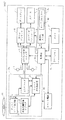
図1を参照して、本発明の第1の実施の形態にかかる再生装置内蔵テレビビジョン受像器について説明する。本例にかかる再生装置内蔵テレビジョン受像器(以降、「再生装置内蔵テレビ」と略称する)100Aは、情報が記録されたディスク状の記録媒体11を回転させながら、その記録トラックから情報を再生する再生装置を内蔵している。このような記録媒体11としては、ビデオCDやDVDに代表される光ディスクやハードディスクに代表される磁気ディスクなどが含まれる。そして、再生装置は、回転している記録媒体の記録トラックに対して概ね垂直方向に読み取り部を移動させながら情報を読み取るものが含まれる。なお、本明細書においては、記録媒体11として光ディスクを用いる光ディスク再生装置Paを例として、以下に述べる。
【0040】
再生装置内蔵テレビ100Aは、主にTV入力端子1、ビデオ入力端子2、AV入力切替スイッチ3、RGBプロセッサ4、ディスプレイ5、オーディオコントローラ6、スピーカ7、制御器8a、操作キー入力器9a、ラストメモリ41、および光ディスク再生装置Paを含む。なお、再生装置内蔵テレビ100Aには、上述のもの以外にも多くの構成要素が含まれるが、本発明の特徴を述べるに特に必要ないので説明を割愛する。
【0041】
操作キー入力器9aは、図12に示した操作キー入力器9に、R−TUNEキー42が追加されて構成されている。R−TUNEキー42は、直前に選択したチャンネルに戻すこと(つまりRapid TUNE)のユーザの要求を入力する手段である。なお、操作キー入力器9aは、赤外線あるいは無線によるリモートコントローラによる入力手段を含む。
【0042】
なお、R−TUNEキー42は、以下に述べるような主に3種類の異なるテレビジョン視聴形態を選択的に提供するために設けられている。
1番目の視聴形態においては、ある放送局から放送されている番組(テレビ放送)を視聴している時に初めて操作されると、テレビチューナのチャンネルが操作される前に視聴していた番組の放送局に切り替えられる。そして、再度操作されると、テレビチューナのチャンネルは、初めて操作された時に視聴していた番組の放送局に再び切り替えられる。
2番目の視聴形態においては、光ディスク11を再生視聴している時に操作されると、光ディスク11の再生が中断されて、光ディスク11の再生視聴の前に選択視聴されていた番組の放送局からの放送が視聴に供される。そして、再度操作されると、中断されていた光ディスク11の再生が再開されて視聴に供される。
3番目の視聴形態においては、ビデオカセットレコーダでビデオコンテンツを再生して視聴している時に操作されると、この再生ビデオコンテンツに代わって、このビデオコンテンツの視聴の前に視聴していたテレビ放送が視聴に供される。そして、再度操作されると、再生ビデオコンテンツが再度視聴に供される。
【0043】
さらに、ラストメモリ41には、直前に選択されたチャンネル番号等の、ユーザが新たな選択をおこなうまで有効であった選択内容が記憶される。なお、ユーザによる選択がおこなわれない場合のために、ラストメモリ41には、予め定められた選択情報が初期値として記憶されており、ユーザが選択をおこなうたびに記憶されている選択情報が更新される。
【0044】
光ディスク再生装置Paは、ディスク再生制御器12、再生位置記憶レジスタ13、AVデコーダ20、およびディスクデータ読取器30を含む。 ディスクデータ読取器30は、光ディスク11を回転させながら、レーザ光を照射して情報を読み出す。AVデコーダ20は、ディスクデータ読取器30に接続されて、光ディスク11から読み出された映像および音声成分をデコードして内部AV信号Savを生成する。なお、AVデコーダ20およびディスクデータ読取器30については、後ほど図2および図3を参照してそれぞれ詳しく説明する。
【0045】
再生位置記憶レジスタ13は、光ディスク11の再生中断時に、その再生中断位置を記憶する。これは、後にユーザが光ディスク11の再生の再開を指示した場合に、中断された位置から再生を再開できるようにするためである。
【0046】
ディスク再生制御器12は、ディスクデータ読取器30、AVデコーダ20、再生位置記憶レジスタ13、および制御器8aに双方向に接続されている。つまり、ディスク再生制御器12は、制御器8aからの制御信号に基づいてディスクデータ読取器30およびAVデコーダ20の動作を制御するとともに、ディスクデータ読取器30から入力される再生制御信号と、AVデコーダ20から入力される再生記録信号とに基づいてディスクデータ読取器30の動作をモニターして、モニター結果を制御器8aに出力する。制御器8aは、当該モニター結果に基づいて、ディスク再生制御器12の動作を決定して制御する。
【0047】
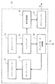
図2を参照して、AVデコーダ20について説明する。AVデコーダ20は、SDRAM21、ビデオデコーダ22、オーディオデコーダ23、NTSCデコーダ24、DAC25、およびDAC26を含む。SDRAM21は、16Mbのメモリで構成されて、ビデオデコーダ22にワーキングエリアを提供する。
【0048】
ビデオデコーダ22は、ディスクデータ読取器30に接続されて、再生信号Spが入力される。ビデオデコーダ22は、入力される再生信号Spの音声成分をオーディオデコーダ23に出力するとともに、映像成分をMPEGデータおよびMP@MLに代表される各種フォーマットに復号して映像信号を生成する。
【0049】
NTSCデコーダ24は、ビデオデコーダ22に接続されて、入力される映像信号をデジタルNTSC信号に変換する。DAC25は、NTSCデコーダ24に接続されて、入力されるデジタルNTSC信号をデジタル/アナログ変換してビデオ信号Svを生成する。なお、DAC25は、上述のAV入力切替スイッチ3に接続されている。
【0050】
オーディオデコーダ23は、ビデオデコーダ22に接続されて、入力される再生信号Spに含まれるAC3、MPEG、およびリニアPCMに代表される各種フォーマットの音声データを復号して音声データを生成する。DAC26は、オーディオデコーダ23に接続されて、入力される音声信号をデジタル/アナログ変換してオーディオ信号Saを生成する。なお、DAC26は、上述のAV入力切替スイッチ3に接続されている。このようにして、DAC25からの出力であるビデオ信号SvおよびDAC26からの出力であるオーディオ信号Saは、上述の内部AV信号SavとしてAV入力切替スイッチ3に出力される。
【0051】
図3を参照して、ディスクデータ読取器30について説明する。ディスクデータ読取器30は、スピンドルモータ31、モータードライバ32、光ピックアップ33、ヘッドアンプ34、信号処理器35、ディスクサーボ制御器36、およびデスクランブラ37を含む。モータードライバ32は、光ディスク11を回転させるスピンドルモータ31を駆動させる。
【0052】
光ピックアップ33は回転している光ディスク11の記録面からデータを読み取って、読み取り信号を生成する。ヘッドアンプ34は、光ピックアップ33から入力される読み取り信号を増幅して信号処理器35およびディスクサーボ制御器36に出力する。
【0053】
信号処理器35は、入力された読み取り信号の中のコンテンツ情報成分をデジタル信号に変換して、デスクランブラ37に出力する。デスクランブラ37は、入力されたデジタル読み取り信号をデスクランブルして、上述の再生信号Spを生成する。
【0054】
ディスクサーボ制御器36は、ヘッドアンプ34から入力された読み取り信号の中の制御情報成分に基づいて、光ディスク11の回転状態を示すサーボ制御信号Scを生成する。上述のように、ディスク再生制御器12は、このサーボ制御信号Scによってディスクデータ読取器30の動作を制御する。ディスクサーボ制御器36は、ディスク再生制御器12からの指示に基づいて、モータードライバ32を制御する。
【0055】
上述の如く構成された再生装置内蔵テレビ100Aの動作について、以下に簡単に説明する。ユーザが光ディスク再生装置Paから出力される内部AV信号Savの表示再生を所望する場合、ユーザは図1に示す操作キー入力器9aを操作して、その意志を入力する。操作キー入力器9aは、ユーザの操作に対応する操作信号Soを生成して制御器8aに出力する。制御器8aは、操作信号Soに基づいて、AV入力切替スイッチ3の接続先を、TV入力端子1あるいはビデオ入力端子2から光ディスク再生装置Paに切り替えさせる。同時に、制御器8aは、光ディスク再生装置Paのディスク再生制御器12に対し再生要求をおこなう。
【0056】
ディスク再生制御器12は、ディスクデータ読取器30に対し読取制御をおこなう。ディスクデータ読取器30は、モータードライバ32を動作させ、スピンドルモータ31を回転させる。また光ピックアップ33の読取部を適正位置に移動させ、光ディスク11からデータを光信号として読み出す。
【0057】
読み出されたデータは、ヘッドアンプ34で増幅され、信号処理器35およびディスクサーボ制御器36に供給される。ディスクサーボ制御器36は読み出された信号よりスピンドルモータ31の回転を正しく制御するためのサーボ制御をモータードライバ32に対しておこなう。また、信号処理器35は、読み出された信号をデジタル化するための処理をおこないデスクランブラ37に供給する。
【0058】
デスクランブラ37は、送られて来た信号のスクランブルを解読し、処理しやすい形態に変換した再生信号SpをAVデコーダ20に供給する。ビデオデコーダ22はSDRAM21を用いて、AVデコーダ20に供給された再生信号Spを映像データと音声データにデコードする。
【0059】
オーディオデコーダ23は、音声データをさらに復号しデジタル音声データとしてDAC26に出力する。デジタル音声データは、DAC26でアナログのオーディオ信号Saに変換される。ビデオデコーダ22から出力される映像データは、NTSCエンコーダでデジタル形式NTSCに変換された後、DAC25でさらにビデオ信号Svに変換される。
【0060】
これらのオーディオ信号Saおよびビデオ信号Svは、内部AV信号SavとしてAV入力切替スイッチ3に入力される。つまり、ビデオ信号Svは、AV入力切替スイッチ3を介してRGBプロセッサ4に入力され、RGB信号に変換され、CRT等のディスプレイ5で表示される。同様に、オーディオ信号Saも、AV入力切替スイッチ3を介してオーディオコントローラ6に入力され、音量、およびトーンが制御された後に、スピーカ7で音声として出力される。
【0061】
次に、ユーザが光ディスク11を再生中に、光ディスク11の再生を開始する直前に視聴していたテレビ放送を再び視聴することを所望する場合の動作について説明する。なお、視聴していたテレビ放送とは、視聴していたチャンネルにおける放送を意味する。ユーザは操作キー入力器9aのR−TUNEキー42を操作して、自身の視聴していたテレビ放送の再視聴の要求を入力する。操作キー入力器9aは、このユーザの操作に対応する操作信号Soを生成して制御器8aに出力する。
【0062】
制御器8aは、操作信号Soに基づいて、ユーザのR−TUNEキー42の操作状態に応じて、上述の3種類の視聴形態を実現するべく再生装置内蔵テレビ100Aを制御する。3種類の視聴形態をAV入力切替スイッチ3の観点から説明する。いま、TV入力端子1にはN種類の放送局から、テレビ放送がN種類のチャンネルでテレビジョン信号Stvとして配信されているとする(Nは任意の自然数)。この場合、配信元の放送局(チャンネル)を識別するために、テレビジョン信号Stv(N)と表現する。
【0063】
上述の1番目の視聴形態においては、ユーザはまず、チャンネルNの放送局からテレビジョン信号Stv(N)で配信されるテレビ放送を視聴していた後に、チューナを切り替えてチャンネルN−1の放送局からテレビジョン信号Stv(N−1)で配信されるテレビ放送を視聴している状態を想定する。つまり、AV入力切替スイッチ3は入力信号源としてTV入力端子1に接続し、入力されるテレビジョン信号Stv(N−1)がRGBプロセッサ4およびオーディオコントローラ6に供給されている。
【0064】
そして、R−TUNEキー42が操作されると、制御器8aはAV入力切替スイッチ3を引き続きTV入力端子1に接続させるとともに、テレビジョン受信機のチューナのチャンネルをN−1から、ラストメモリ41から読み出したチャンネルNに切り替え、さらにラストメモリ41にチャンネルN−1を記憶させる。結果、TV入力端子1からはテレビジョン信号Stv(N−1)の代わりにテレビジョン信号Stv(N)が入力されて、テレビジョン信号Stv(N)で配信されるテレビ放送が視聴に供される。なお、R−TUNEキー42を操作する前に、チャンネルN−1のテレビ放送を視聴していない、つまりNが記憶されていない場合は、ラストメモリ41に記憶されている初期値のチャンネルに切り替えられる。
【0065】
2番目の視聴形態においては、ユーザはまず、チャンネルNの放送局からテレビジョン信号Stv(N)で配信されるテレビ放送を視聴している途中で、光ディスク再生装置Paによる光ディスク11の再生を開始して視聴している場合を想定する。つまり、AV入力切替スイッチ3は入力信号源として光ディスク再生装置Paに接続し、入力される内部AV信号SavがRGBプロセッサ4およびオーディオコントローラ6に供給されている。
【0066】
R−TUNEキー42が操作されると、制御器8aは光ディスク再生装置Paを一時停止させるとともに、テレビジョン受信機のチューナのチャンネルをラストメモリ41から読み出したチャンネルNに設定する。さらに、制御器8aはAV入力切替スイッチ3をTV入力端子1に接続させる。結果、内部AV信号Savの代わりにテレビジョン信号Stv(N)がRGBプロセッサ4およびオーディオコントローラ6に供給されて、チャンネルNで配信されるテレビ放送が視聴に供される。
【0067】
そして、再度操作されると、制御器8aは中断されていた光ディスク11の再生を再開させ、現在のチャンネルNをラストメモリ41に記憶させ、そしてAV入力切替スイッチ3を光ディスク再生装置Paに接続させる。結果、内部AV信号Savが再びRGBプロセッサ4およびディスプレイ5に供給されて光ディスク11が再生視聴に供される。
【0068】
3番目の視聴形態においては、ユーザはまず、チャンネルNの放送局からテレビジョン信号Stv(N)で配信されるテレビ放送を視聴している途中で、ビデオ入力端子2に接続された据え置き型ビデオカセットレコーダによるビデオコンテンツを再生視聴している場合を想定する。つまり、AV入力切替スイッチ3はビデオ入力端子2に接続し、入力される外部AV信号SvcがRGBプロセッサ4およびオーディオコントローラ6に供給されている。
【0069】
R−TUNEキー42が操作されると、制御器8aはテレビジョン受信機のチューナのチャンネルをラストメモリ41から読み出したチャンネルNに設定するとともに、AV入力切替スイッチ3をTV入力端子1に接続させる。結果、外部AV信号Svcの代わりにテレビジョン信号Stv(N)がRGBプロセッサ4およびオーディオコントローラ6に供給されて、チャンネルNで配信されるテレビ放送が視聴に供される。
【0070】
そして、再度操作されると、制御器8aは、現在のチャンネルNをラストメモリ41に記憶させるとともに、AV入力切替スイッチ3をビデオ入力端子2に接続させる。結果、外部AV信号Svcが再びRGBプロセッサ4およびディスプレイ5に供給されてビデオコンテンツが再生視聴に供される。
【0071】
上述の2番目の視聴形態に関して述べたように、ユーザがR−TUNEキー42を操作して、AV入力切替スイッチ3に対して光ディスク再生装置PaからTV入力端子1への切り替えを要求すれば、制御器8aはAV入力切替スイッチ3をTV入力端子1に切り替えるとともにディスク再生制御器12に対し、保持要求をおこなう。ディスク再生制御器12は、この要求を受けると直ちに再生位置記憶レジスタ13に現在の再生位置データを書き込みディスクデータ読取器30の動作を停止させる。さらにR−TUNEキー42が操作されると、制御器8aはAV入力切替スイッチ3を光ディスク再生装置Paに切り替え、ディスク再生制御器12に対して保持解除要求をおこなう。ディスク再生制御器12は、再生位置記憶レジスタ13の書込値に基づいて、記憶内容読取りディスクデータ読取器30の読み出し位置の再設定をおこなう。そして、ディスクデータ読取器30は、再設定された位置から光ディスク11からデータ読み出しを再開してAVデコーダ20に出力する。
【0072】
(第2の実施の形態)
図4を参照して、本発明の第2の実施の形態にかかる再生装置内蔵テレビについて説明する。本例にかかる再生装置内蔵テレビ100Bは、光ディスク再生装置Paが光ディスク再生装置Pbに置き換えられている点を除いて図1に示した再生装置内蔵テレビ100Aと同様に構成されている。さらに、光ディスク再生装置Pbは、ディスクデータ読取器30が停止していることを示す映像をディスプレイ5に表示させるために設けられているスクリーンセーバ14が付加されている点を除けば光ディスク再生装置Paと同様に構成されている。よって、第1の実施の形態にかかる再生装置内蔵テレビ100Aと共通の部分についての説明は省くとともに、本実施の形態にかかる再生装置内蔵テレビ100Bに固有の特徴についてのみ説明する。
【0073】
以下に、再生装置内蔵テレビ100Bの動作について説明する。本実施の形態においては、上述の2番目の視聴形態における動作が上述の第1の実施の形態の場合と異なる。つまり、光ディスク11を再生視聴している時にR−TUNEキー42が操作されると、制御器8aはディスク再生制御器12に対して一時保持要求をおこなう。
ディスク再生制御器12は、直ちに現在の再生位置を再生位置記憶レジスタ13に記憶させると同時にディスクデータ読取器30を停止させる。ディスク再生制御器12はさらに、AVデコーダ20を経由して、スクリーンセーバ14を駆動させスクリーンセーバ信号SsをAVデコーダ20に供給させる。AVデコーダ20は、光ディスク11からの再生信号の代わりに、スクリーンセーバ信号Ssを内部AV信号SavとしてAV入力切替スイッチ3に出力する。
【0074】
そして、R−TUNEキー42が再び操作されて、再び光ディスク11の再生視聴が要求された時に、制御器8aはディスク再生制御器12にスクリーンセーバ14の動作を停止させ、再生位置記憶レジスタ13の内容を読み取りその位置から再生するようにディスクデータ読取器30を動作させる。
【0075】
(第3の実施の形態)
図5を参照して、本発明の第3の実施の形態にかかる再生装置内蔵テレビについて説明する。本例にかかる再生装置内蔵テレビ100Cは、光ディスク再生装置Paが光ディスク再生装置Pcに置き換えられている点を除いて図1に示した再生装置内蔵テレビ100Aと同様に構成されている。さらに、光ディスク再生装置Pcは、光ディスク11に記録されているデータがシングルシーケンシャル構造とマルチシーケンシャル構造のいずれであるかを記憶するシーケンスレジスタが付加されている点を除いて光ディスク再生装置Paと同様に構成されている。よって、第1の実施の形態にかかる再生装置内蔵テレビ100Aと共通の部分についての説明は省くとともに、本実施の形態にかかる再生装置内蔵テレビ100Cに固有の特徴についてのみ説明する。
【0076】
再生装置内蔵テレビ100Cは、光ディスク11として、DVDに代表されるビデオディスクの再生に対応している。このようなビデオディスクは、コンテンツデータの構造から、シングルシーケンシャルタイプとマルチシーケンシャルタイプとのいずれかに分類される。コンテンツが映画などのビデオディスクは、一般的にシングルシーケンシャル構造でデータが記録されている。一方、デモンストレーション等の特殊用途のビデオディスクは、マルチシーケンシャル構造でデータで記録されている。
【0077】
シングルシーケンシャルタイプのビデオディスクは、一時保持をした際の再生位置を明確に把握できる。しかしながら、マルチシーケンシャルタイプのビデオディスクは、一般的に、一時保持処理をした際の再生位置を明確に把握できず、保持した時点から再生を再開しようとすると、予期しないところから再生されるような不都合が起こりうる。このような事態を避けるために、本実施の形態においては、光ディスク11がシングルシーケンシャルタイプの場合と、マルチシーケンシャルタイプの場合で、上述の2番目の視聴形態における動作を変化させるものである。
【0078】
光ディスク11がデータ構造タイプがシングルシーケンシャルであるのか、マルチシーケンシャルであるのかは、光ディスク11の再生開始時にディスク再生制御器12によって判別されて、再生位置記憶レジスタ13に記憶される。そして、ユーザがR−TUNEキー42を操作して光ディスク再生装置Pcの一時保持要求をした場合、制御器8aはディスク再生制御器12に現在再生されているディスクのデータ構造タイプを問い合わせる。ディスク再生制御器12は、シーケンスレジスタ15から光ディスク11のデータ構造タイプを読み出して制御器8aに知らせる。
【0079】
光ディスク11がシングルシーケンシャルタイプであれば、制御器8aは、第1の実施の形態にかかる再生装置内蔵テレビ100Aと同様に、ディスク再生制御器12に対して一時保持指令を発する。一方、光ディスク11がマルチシーケンシャルタイプであれば、制御器8aはディスク再生制御器12に対し一時保持指令はおこなわない。一時保持指令が、AV入力切替スイッチ3の切り替えを伴う場合は、制御器8aはAV入力切替スイッチ3の切り替え動作のみをおこなわせる。
【0080】
(第4の実施の形態)
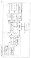
図6を参照して、本発明の第4の実施の形態にかかる再生装置内蔵テレビについて説明する。本例にかかる再生装置内蔵テレビ100Dは、光ディスク再生装置Paに電力を供給するユニット電源16が付加されている点を除いて図1に示した再生装置内蔵テレビ100Aと同様に構成されている。ユニット電源16は、制御器8aによって制御されて、外部の主電源(図示せず)から供給される主電力から光ディスク再生装置Paの駆動に必要なユニット電力を生成する。
【0081】
本実施の形態においては、光ディスク再生装置Paの一時保持要求時の電力消費を改善することを目的としている。つまり、上述の2番目の視聴形態における動作が第1の実施の形態の場合と異なる。具体的には、光ディスク11を再生視聴している時にR−TUNEキー42が操作されると、制御器8aはディスク再生制御器12に対して一時保持要求をおこなう。ディスク再生制御器12は、現在の再生位置を判別し、再生位置記憶レジスタ13にその内容を書き込むとともに、停止要求をディスクデータ読取器30に対しておこなう。さらに、ディスク再生制御器12は、データバックアップ後、完了報告を制御器8aに対しておこなう。制御器8aはその内容を検出した後、ユニット電源16を停止させる。
【0082】
そして、操作キー入力器9より再度、光ディスク再生装置Paの再生要求がなされた場合、制御器8aはユニット電源16を動作させる。ユニット電源16からの電力供給が再開されて、ディスク再生制御器12は動作を開始し、まず再生位置記憶レジスタ13の書き込み内容を判別する。この内容が有効なものであればこの内容を読み取りこの位置から再生を開始するようにディスクデータ読取器30に対し指令をおこなう。制御器8aは、その後直ちにAV入力切替スイッチ3を光ディスク再生装置Pa側に切り替える。このようにして、光ディスク再生装置Paを稼働する必要が無い一時保持(待機)時に、電力供給に断つことによって、無駄な電力消費を防止できる。
【0083】
図7を参照して、本発明の第4の実施の形態にかかる再生装置内蔵テレビの変形例について説明する。本例にかかる再生装置内蔵テレビ100Drは、再生装置内蔵テレビ100Dr全体に電力を供給する主電源MPSが付加されているとともに、ユニット電源16はユニット電力供給器16rに置き換えられている。ユニット電力供給器16rは、主電力から光ディスク再生装置Paの駆動用ユニット電力を生成するユニット電力生成器UPSと主電源供給スイッチPSWを含む。ユニット電力生成器UPSは主電源供給スイッチPSWを介して主電源MPSに接続される。
【0084】
これは、再生装置内蔵テレビ100Dにおける光ディスク再生装置Paの一時保持要求時の電力消費低減をさらに改善することを目的としているつまり、上述の2番目の視聴形態における光ディスク再生装置Paへの電力供給方法が第4の実施の形態の場合と若干異なる。具体的には、再生装置内蔵テレビ100Drにおいては、光ディスク再生装置Paに対する一時保持要求時には、制御器8aは電力供給スイッチSWを操作して、ユニット電力生成器UPS(しいては、ユニット電力供給器16r)への主電力の供給を絶つ。一方、再生装置内蔵テレビ100Dにおいては、ユニット電源16を停止させる時にも、ユニット電源16に対する主電力の供給を断たない。
【0085】
つまり、ユニット電源16やユニット電力供給器16r(ユニット電力生成器UPS)は、入力される一時電力を変換して、二次電力を生成してユニット電力として出力する電力変換器である。電力変換器は、二次電力を出力しなくても、印加されている一時電力を熱などの形で放出するエネルギーロスを生じる。このエネルギーロスは光ディスク再生装置Pa全体やその一部の構成要素によって消費される電力に比べると小さい。しかしながら、再生装置内蔵テレビ100Dに通電されている間は常に生じる、稼働の観点から不必要な電力消費である。本変形例においては、そのような電力変換にかかる不必要なロスをも防止するものである。
【0086】
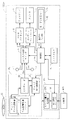
(第5の実施の形態)
図8を参照して、本発明の第5の実施の形態にかかる再生装置内蔵テレビについて説明する。本例にかかる再生装置内蔵テレビ100Eは、AV入力切替スイッチ3に対する切り替え要求がなされた時点から任意時間Tを測定するタイマ17が付加されている点を除いて図6に示した再生装置内蔵テレビ100Dと同様に構成されている。
【0087】
本実施の形態においては、光ディスク再生装置Paの一時保持要求時の光ディスク再生装置Paの停止を所定時間だけ遅延させることによって、ユーザの使用感、電力消費および製品寿命の改善することを目的としている。一般的に電力消費の観点からは、一時保持要求時には光ディスク再生装置Paへの電力供給を直ちに絶つことが望ましい。しかしながら、一旦停止した光ディスク再生装置Paを再起動させるには、運転時に比べて多大な起動電力が必要になる。そのため、ユーザが光ディスク再生装置Paの視聴時を中断して、例えばテレビ放送の内容を確認後、再度光ディスク再生装置Paの視聴を再開する場合などは、その中断時間によっては、光ディスク再生装置Paの稼働を継続させておいた方が、電力消費を抑えることができる。さらに、光ディスク再生装置Paの寿命の観点からみると、多大な起動電力での再起動の回数を抑える方が有利である。また、光ディスク再生装置Paの再起動には時間を要するために、ユーザが光ディスク再生装置Paの視聴を中断後に、再度視聴する際に、視聴が待たされるというユーザの使用感を損なうと言う問題がある。
【0088】
つまり、省資源を含めた省エネルギーの観点から言えば、一時保持要求時には光ディスク再生装置Paへの電力供給を直ちに絶つことが最善とは言えない。光ディスク再生装置Paへの即時電力供給停止による省電力量と、光ディスク再生装置Paの再起動に要する消費電力量と、連続稼働と断続稼働による光ディスク再生装置Paの寿命という3つの主因子間のバランスをとることが大事である。さらに、商品としてのユーザの使用感も大事な4番目の主因子である。これらの因子の最適値は、装置毎にその物性や使用状態に応じて適正に決定されるものであり、一義的に決めることはできない。そこで、本変形例においては、これらの異なる4つの主因子を考慮した再生装置内蔵テレビを提供するべく、一時保持要求時には光ディスク再生装置Paへの電力供給停止時間を調整する手段をさらに提供するものである。
【0089】
つまり、上述の2番目の視聴形態における動作が第5の実施の形態の場合と若干異なる。具体的には、R−TUNEキー42により光ディスク再生装置PaからTV入力側に入力の切り替え要求がなされた場合、制御器8aは、直ちにタイマ17の動作を開始させる。制御器8aは、さらにAV入力切替スイッチ3に対し入力の切り替えを指示するとともに、ディスク再生制御器12に対して一時保持を指示する。ディスク再生制御器12は、現時点での再生位置を再生位置記憶レジスタ13に対し書き込んだ後、ディスクデータ読取器30を停止させる。その後、任意時間Tが経過(タイマ17からの割り込み信号を検出)する迄に、操作キー入力器9による入力信号の切り替え要求がなされない場合、制御器8aは、ディスク再生制御器12に対し停止処理をおこなう。
【0090】
そして、ディスク再生制御器12から完了信号を受け取ると、制御器8aは直ちにユニット電源16を停止させる。その後、R−TUNEキー42が操作されて光ディスク再生装置Paの再生が指示されると、制御器8aはユニット電源16を立ち上げて、光ディスク再生装置Paに対する電力供給を再開する。ディスク再生制御器12は稼働を再開して、再生位置記憶レジスタ13に記憶されている再生記憶位置を読み出しディスクデータ読取器30に対し位置設定の処理をおこなう。ディスクデータ読取器30から読み出されたデータはAVデコーダ20によってAVデータ再生されAV入力切替スイッチ3を介して提示される。
【0091】
図9を参照して、本発明の第5の実施の形態にかかる再生装置内蔵テレビの変形例について説明する。本例にかかる再生装置内蔵テレビ100Erは、再生装置内蔵テレビ100Er全体に電力を供給する主電源MPSが付加されているとともに、ユニット電源16はユニット電力供給器16rに置き換えられている。これらの主電源MPSおよびユニット電力供給器16rは、図7を参照して説明した、再生装置内蔵テレビ100Erにおけるのと同じ構成のものが同じ目的のために設けられている。再生装置内蔵テレビ100Eにおける光ディスク再生装置Paの一時保持要求時の電力消費低減をさらに改善することを目的としている。つまり、上述の2番目の視聴形態における光ディスク再生装置Paへの電力供給方法が第5の実施の形態の変形例である再生装置内蔵テレビ100Drの場合と同様に、再生装置内蔵テレビ100Erにおいても、ユニット電力供給器16rへの主電力の供給を絶って光ディスク再生装置Paを停止させる。
【0092】
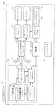
(第6の実施の形態)
図10を参照して、本発明の第6の実施の形態にかかる再生装置内蔵テレビについて説明する。本例にかかる再生装置内蔵テレビ100Fは、上述の第1の実施の形態、第2の実施の形態、第3の実施の形態、第4の実施の形態、および第5の実施の形態にかかる再生装置内蔵テレビの特徴を全て取り込んで構成されている。つまり、再生装置内蔵テレビ100Fは、図8に示した再生装置内蔵テレビ100Eの光ディスク再生装置Paにスクリーンセーバ14とシーケンスレジスタ15が不要されて構成された光ディスク再生装置Peに置き換えられている。なお、光ディスク再生装置Peにおいて、スクリーンセーバ14との関係は図4を参照して光ディスク再生装置Pbに関して説明した通りであり、シーケンスレジスタ15との関係は図5を参照して光ディスク再生装置Pcに関して説明した通りである。
【0093】
本実施の形態においても、光ディスク再生装置Peの一時保持要求時の電力消費を改善することを目的としている。つまり、R−TUNEキー42の操作により元のチャンネル番号に切り替え要求がなされると、制御器8aはその内容を判別し、ラストメモリ41に記憶されたチャンネル番号をAV入力切替スイッチ3に接続されるTV入力のチューナの設定をおこなうと同時にAV入力切替スイッチ3をTV入力側に切り替える。
【0094】
さらに制御器8aは、ディスク再生制御器12に対し、シーケンシャル判別要求をおこなう。ディスク再生制御器12は、シーケンスレジスタ15の内容を制御器8aに対し返す。マルチシーケンシャルであれば、制御器8aは、ディスク再生制御器12に対し停止要求をおこなう。それに伴いディスク再生制御器12は、ディスクデータ読取器30を停止させるとともに、スクリーンセーバ14を動作させAVデコーダ20を介してスクリーンセーバ信号SsをAV入力切替スイッチ3に出力する。
【0095】
シーケンスレジスタ15の内容がシングルシーケンシャルであれば、タイマ17を起動させるとともにディスク再生制御器12に対し一時保持要求をおこなう。ディスク再生制御器12は、現在の再生位置を再生位置記憶レジスタ13に書き込みディスクデータ読取器30を停止させる。
【0096】
任意の時間T経過するまでに、操作キー入力器9aに対し、光ディスク11再生装置11dへの再生処理要求がおこなわれた場合、制御器8aは直ちにそれを判別し、ディスク再生制御器12に要求する。ディスク再生制御器12は、再生位置記憶レジスタ13から再生位置を読み出し、ディスクデータ読取器30に対しその位置を設定し再生を開始するように指令する。
【0097】
任意時間Tが経過するまでに、光ディスク11再生装置11dへの再生処理要求が行われれない場合には、タイマ17より割り込み要求が制御器8aに対しておこなわれる。制御器8aは、光ディスク11再生装置11dのバックアップ完了を確認した後、ユニット電源16を停止させて、光ディスク再生装置Paへの電力供給を絶つ。
【0098】
光ディスク再生装置Paへの電力供給断絶の後に、R−TUNEキー42が再度操作がなされると、制御器8aはその内容を判別しユニット電源16を立ち上げる。電源が立ち上がったことによりディスク再生制御器12は、シーケンスレジスタ15の内容を読取り、シングルシーケンシャルであれば、再生位置記憶レジスタ13に記憶された位置からの、マルチシーケンシャルであれば初期位置からの再生をディスクデータ読取器30に対しておこなう。
【0099】
ディスクデータ読取器30から呼び出されたデータはAVデコーダ20でAV信号にデコードされ、制御器8aにより光ディスク11側に切り替えられたAV入力切替スイッチ3を介してRGBプロセッサ4によりRGB信号に復号されディスプレイ5に表示され、オーディオコントローラ6で音声に復号されスピーカ7より再生される。
【0100】
図11を参照して、本発明の第6の実施の形態にかかる再生装置内蔵テレビの変形例について説明する。本例にかかる再生装置内蔵テレビ100Frは、再生装置内蔵テレビ100Fr全体に電力を供給する主電源MPSが付加されているとともに、ユニット電源16はユニット電力供給器16rに置き換えられている。これらの主電源MPSおよびユニット電力供給器16rは、図7を参照して説明した、再生装置内蔵テレビ100Erにおけるのと同じ構成のものが同じ目的のために設けられている。再生装置内蔵テレビ100Eにおける光ディスク再生装置Paの一時保持要求時の電力消費低減をさらに改善することを目的としている。
【0101】
つまり、上述の2番目の視聴形態における光ディスク再生装置Peへの電力供給方法が第5の実施の形態の変形例である再生装置内蔵テレビ100Erの場合と同様に、再生装置内蔵テレビ100Frにおいても、ユニット電力供給器16rへの主電力の供給を絶って光ディスク再生装置Paを停止させる。またキー操作に関しては、R−TUNEキー42を用いる場合を例に説明したが、操作キー入力器9aより直接チャンネル番号を入力するように場合も同等の効果が得られ、本発明に含まれることは言うまでもない。
【図面の簡単な説明】
【図1】本発明の第1の実施の形態にかかる再生装置の構成を示すブロック図である。
【図2】図1に示したAVデコーダの詳細な構成を示すブロック図である。
【図3】図1に示したディスクデータ読取器の詳細な構成を示すブロック図である。
【図4】本発明の第2の実施の形態にかかる再生装置の構成を示すブロック図である。
【図5】本発明の第3の実施の形態にかかる再生装置の構成を示すブロック図である。
【図6】本発明の第4の実施の形態にかかる再生装置の構成を示すブロック図である。
【図7】図6に示した再生装置の変形例の構成を示すブロック図である。
【図8】本発明の第5の実施の形態にかかる再生装置の構成を示すブロック図である。
【図9】図8に示した再生装置の変形例の構成を示すブロック図である。
【図10】本発明の第6の実施の形態にかかる再生装置の構成を示すブロック図である。
【図11】図10に示した再生装置の変形例の構成を示すブロック図である。
【図12】従来の再生装置の構成を示すブロック図である。
【符号の説明】
100A、100B、100C、100D、100E、100Er、100F、100Fr、1000 再生装置内蔵テレビ
1 TV入力端子
2 ビデオ入力端子
3 AV入力切替スイッチ
4 RGBプロセッサ
5 ディスプレイ
6 オーディオコントローラ
7 スピーカ
8、8a 制御器
9、9a 操作キー入力器
41 ラストメモリ
42 R−TUNEキー
Pa 光ディスク再生装置
12 ディスク再生制御器
13 再生位置記憶レジスタ
14 スクリーンセーバ
15 シーケンスレジスタ
16 ユニット電源
16r ユニット電力供給器16
SW 電力供給スイッチ
MPS 主電源
20 AVデコーダ
21 SDRAM
22 ビデオデコーダ
23 オーディオデコーダ
24 NTSCデコーダ
25、26 DAC
30 ディスクデータ読取器
31 スピンドルモータ
32 モータードライバ
33 光ピックアップ
34 ヘッドアンプ
35 信号処理器
36 ディスクサーボ制御器
37 デスクランブラ[0001]
BACKGROUND OF THE INVENTION
The present invention relates to a playback apparatus that switches between a video / audio signal input from the outside and a video / audio signal played back from a recording medium such as a built-in optical disk.
[0002]
[Prior art]
FIG. 12 schematically shows a configuration of a conventional television receiver with a built-in video CD reproducing device proposed in Japanese Patent Application No. 6-30003 (Japanese Patent Laid-Open No. 7-240882). A
[0003]
The
On the other hand, the
[0004]
The
The AV
[0005]
The
Similarly, the
[0006]
The
[0007]
The operation of the playback apparatus built-in
[0008]
If the user wishes to watch a television broadcast during video CD playback, the
[0009]
At the same time that the connection destination is switched to the video
[0010]
[Problems to be solved by the invention]
As represented by the above-mentioned
[0011]
Furthermore, not only during the pause (standby) period, but also when the user switches the service providing source from a video CD that is a built-in playback device to a wired broadcast that is an external signal source, and is left as it is. Then, the rotation of the video CD and the operation of the laser irradiation unit are continued, and not only energy saving but also deterioration of the quality of the apparatus leads to a shortened life.
[0012]
The present invention refers to energy saving, device life, and user's feeling of use with respect to playback display performed by switching between an externally input video / audio signal and a video / audio signal played back from a recording medium such as an internal optical disk. An object of the present invention is to provide a reproducing apparatus in which each factor is improved while balancing between different factors.
[0013]
[Means for Solving the Problems and Effects of the Invention]
According to a first aspect of the present invention, first information read from an internal recording medium and second information provided by a plurality of channels supplied from an information source provided externally according to a user's selection A playback device for selectively switching between and
An information signal generator for reading the first information from the recording medium and generating a first information signal;
An information signal input device for indicating a requested channel to an information source and receiving a second information provided by the indicated channel and inputting a second information signal;
A selection signal generator for generating a selection signal indicative of the user's selection in response to an operation by the user;
An information signal selector for selecting one of the first and second information signals in response to the selection signal;
An information regenerator for reproducing information from the first or second information signal selected by the information signal selector;
An information reproduction controller for controlling the reproduction start state of the first and second information when switching the information signal to be reproduced based on the selection signal;
The information reproduction controller
A reading position storage for storing a reading position of the first information in the recording medium;
A channel store for storing a request channel that the information signal input unit instructs the information source;
When the first information is selected by the selection signal, the request channel currently instructed by the information signal input device to the information source is stored in the channel memory and the reading stored in the reading position memory is stored. A first controller for controlling the information signal generator to read the first information from the position;
When the second information is selected by the selection signal, the position where the information signal generator is currently reading the first information is stored in the reading position memory, and the request channel stored in the channel memory is stored. And a second controller for controlling the information signal input device to instruct the information source.
[0014]
As described above, in the first invention, when switching the reproduction information to be displayed during reproduction of information from the recording medium, the reproduction is interrupted after the current reproduction position of the recording medium is stored, When the information reproduction is requested again, the reproduction can be resumed immediately from the stored reproduction interruption position, so that the operation of the recording medium and the information signal generator can be stopped during the waiting period until the reproduction is resumed after the interruption. As a result, it is possible to obtain an excellent improvement effect regarding energy saving, noise, noise, and device life.
[0015]
In a second aspect based on the first aspect, the information reproduction controller further includes a third controller that stops the information signal generator when the second information is selected by the selection signal.
[0016]
In a third aspect based on the second aspect, the information reproduction controller restarts the stopped information signal generator when the first information is selected again by the selection signal. Further included.
[0017]
In a fourth aspect based on the first aspect, the channel memory stores the initialized channel,
When the second information is selected for the first time by the selection signal, the second controller is characterized by instructing the information source of the initially set channel.
[0018]
In a fifth aspect based on the third aspect, the recording medium is an optical disc, and the information signal generator is
A disc data reader for reading data from the recording surface of the optical disc;
An AV decoder that converts the read data into a video and audio signal to generate a first information signal;
The disc data reader is controlled to be stopped and restarted by a third controller and a fourth controller.
[0019]
In a sixth aspect based on the fifth aspect, the information signal generator further includes a screen saver output device for displaying a still image,
The information reproduction controller stops the disc data reader and, when the selection signal is selected to pause the reproduction of the first information, causes the screen saver output unit to output the screen saver video signal instead of the first information signal. A fifth controller for outputting is included.
[0020]
In a seventh aspect based on the fifth aspect, the information signal generator is
A data configuration determiner that determines whether the data recorded on the optical disc from the read data is a single sequential configuration or a multi-sequential configuration;
A data structure storage device for storing the determination result;
The information reproduction controller
When it is determined that the multi-sequential configuration is used, the sixth controller prohibits the first controller from controlling the information signal generator so as to read the first information from the reading position stored in the reading position memory. A controller.
[0021]
An eighth invention according to the first invention further comprises a drive power supply for supplying drive power to the information signal generator,
The third controller includes a power supply stop device that controls the drive power supply to stop the supply of drive power.
[0022]
As described above, in the eighth invention, further energy saving can be achieved by stopping the supply of driving power to the information signal generator.
[0023]
In a ninth aspect based on the eighth aspect, a timer for measuring a predetermined time from the time when the second information is selected by the selection signal;
The power supply stop delay device further delays the operation of the power supply stop device until a predetermined time elapses.
[0024]
As described above, in the ninth invention, it is more advantageous from the viewpoint of energy saving and the life of the apparatus to maintain the operating state than to restart the recording medium and the information signal generator after stopping the operation. This is effective when the waiting time for restarting the playback is short.
[0025]
In a tenth aspect based on the first aspect, the drive power supply is
A driving power generator that generates driving power from main power supplied from a main power source provided outside;
A main power supply switch for connecting the drive power generator to the main power source and supplying main power;
The third controller includes a main power supply stop device that controls the front main power supply switch to stop the supply of the main power.
[0026]
As described above, in the tenth invention, the main power is not supplied to the driving power generator that generates the driving power from the main power, so that the driving power generator itself generates the main power regardless of the information signal generator. It is possible to prevent loss of consumption and further save energy.
[0027]
In an eleventh aspect based on the tenth aspect, a timer for measuring a predetermined time from the time when the second information is selected by the selection signal;
A main power supply stop delay device that delays the operation of the main power supply stop device until a predetermined time elapses.
[0028]
As described above, the same effect as in the ninth invention is obtained.
[0029]
In a twelfth aspect based on the fifth aspect, the information signal generator is
A screen saver output device for displaying still images;
A data configuration determination unit that determines whether the data data recorded on the optical disc is a single sequential configuration or a multi-sequential configuration from the read data;
A data structure storage device for storing the determination result;
The information reproduction controller
Fifth control for stopping the disc data reader and causing the screen saver output device to output a screen saver video signal instead of the first information signal when the reproduction of the first information is selected by the selection signal. And
If the multi-sequential configuration is determined, a sixth controller prohibits the first controller from controlling the information signal generator to read the first information from the read position stored in the read position memory. And a controller.
[0030]
As described above, the effects of the first, second, third, fourth, fifth, sixth, and seventh inventions are combined.
[0031]
A thirteenth aspect of the invention is the twelfth aspect of the invention, further comprising a drive power supply for supplying drive power to the information signal generator,
The third controller includes a power supply stop device that controls the drive power supply to stop the supply of drive power.
[0032]
As described above, the same effect as in the eighth invention is obtained.
[0033]
In a fourteenth aspect based on the thirteenth aspect, a timer for measuring a predetermined time from the time when the second information is selected by the selection signal;
The power supply stop delay device further delays the operation of the power supply stop device until a predetermined time elapses.
[0034]
As described above, the same effect as in the ninth invention is obtained.
[0035]
In a fifteenth aspect based on the twelfth aspect, the drive power source is
A driving power generator that generates driving power from main power supplied from a main power source provided outside;
A main power supply switch for connecting the drive power generator to the main power source and supplying main power;
The third controller includes a main power supply stop device that controls the front main power supply switch to stop the supply of the main power.
[0036]
As described above, the same effect as in the tenth invention is obtained.
[0037]
In a fifteenth aspect based on the fifteenth aspect, a timer for measuring a predetermined time from the time when the second information is selected by the selection signal;
A main power supply stop delay device that delays the operation of the main power supply stop device until a predetermined time elapses.
[0038]
As described above, the same effect as in the ninth invention is obtained.
[0039]
DETAILED DESCRIPTION OF THE INVENTION
(First embodiment)
With reference to FIG. 1, a television vision receiver with a built-in playback device according to a first embodiment of the present invention will be described. The reproduction apparatus built-in television receiver (hereinafter abbreviated as “reproduction apparatus built-in television”) 100A according to the present example reproduces information from the recording track while rotating the disk-shaped
[0040]
The reproduction apparatus built-in
[0041]
The operation
[0042]
The R-
In the first viewing mode, when the first operation is performed while viewing a program (television broadcast) broadcast from a certain broadcasting station, the program being viewed before the channel of the TV tuner is operated is broadcast. Switch to the station. When the operation is performed again, the channel of the TV tuner is switched again to the broadcast station of the program that was being viewed when the operation was performed for the first time.
In the second viewing mode, if the operation is performed while the
In the third viewing mode, if the video content is operated while being played back and viewed on a video cassette recorder, the television broadcast that was being watched before viewing the video content instead of the played video content is displayed. Is available for viewing. When the operation is performed again, the reproduced video content is again viewed.
[0043]
Further, the
[0044]
The optical disk playback apparatus Pa includes a
[0045]
The reproduction
[0046]
The
[0047]
The
[0048]
The
[0049]
The
[0050]
The
[0051]
The
[0052]
The
[0053]
The
[0054]
The
[0055]
The operation of the playback apparatus built-in
[0056]
The
[0057]
The read data is amplified by the
[0058]
The
[0059]
The
[0060]
These audio signal Sa and video signal Sv are input to the AV
[0061]
Next, a description will be given of an operation in a case where the user desires to view again the television broadcast that was viewed immediately before the reproduction of the
[0062]
Based on the operation signal So, the
[0063]
In the first viewing mode described above, the user first watches a television broadcast distributed from the broadcasting station of channel N using the television signal Stv (N), and then switches the tuner to broadcast the channel N-1. A state is assumed in which a television broadcast distributed from the station by the television signal Stv (N-1) is viewed. That is, the AV
[0064]
When the R-
[0065]
In the second viewing mode, the user first starts playback of the
[0066]
When the R-
[0067]
When operated again, the
[0068]
In the third viewing mode, the user first views the stationary video connected to the
[0069]
When the R-
[0070]
When operated again, the
[0071]
As described above with respect to the second viewing mode, if the user operates the R-
[0072]
(Second Embodiment)
With reference to FIG. 4, a television with a built-in playback device according to the second embodiment of the present invention will be described. The reproduction apparatus built-in
[0073]
Hereinafter, an operation of the reproduction apparatus built-in
The
[0074]
When the R-
[0075]
(Third embodiment)
With reference to FIG. 5, a television with a built-in playback device according to the third embodiment of the present invention will be described. The reproduction apparatus built-in
[0076]
The reproduction apparatus built-in
[0077]
Single sequential type video discs can clearly grasp the playback position when temporarily held. However, a multi-sequential type video disc generally cannot clearly grasp the playback position when the temporary holding process is performed, and if playback is resumed from the held point, it may be played from an unexpected place. Inconvenience can occur. In order to avoid such a situation, in the present embodiment, the operation in the second viewing mode described above is changed depending on whether the
[0078]
Whether the optical structure of the
[0079]
If the
[0080]
(Fourth embodiment)
With reference to FIG. 6, a television with a built-in playback device according to the fourth embodiment of the present invention will be described. The playback device built-in
[0081]
The purpose of this embodiment is to improve the power consumption at the time of the temporary holding request of the optical disc playback apparatus Pa. That is, the operation in the second viewing mode described above is different from that in the first embodiment. Specifically, when the R-
[0082]
When the operation key input unit 9 requests the optical disc playback apparatus Pa again, the
[0083]
With reference to FIG. 7, a modification of the television with a built-in playback device according to the fourth embodiment of the present invention will be described. In the reproduction apparatus built-in television 100Dr according to this example, a main power source MPS for supplying power to the entire reproduction apparatus built-in television 100Dr is added, and the
[0084]
This is intended to further improve the power consumption reduction at the time of the temporary holding request of the optical disc playback device Pa in the playback device built-in
[0085]
That is, the
[0086]
(Fifth embodiment)
With reference to FIG. 8, a television with a built-in playback device according to the fifth embodiment of the present invention will be described. The reproduction apparatus built-in
[0087]
In the present embodiment, an object of the present invention is to improve the user's feeling of use, power consumption and product life by delaying the stop of the optical disc playback device Pa when the optical disc playback device Pa is temporarily held for a predetermined time. . In general, from the viewpoint of power consumption, it is desirable to immediately cut off the power supply to the optical disc playback apparatus Pa when a temporary holding request is made. However, in order to restart the optical disk reproducing apparatus Pa that has been stopped, a large amount of startup power is required as compared to during operation. Therefore, when the user interrupts viewing of the optical disc playback apparatus Pa, for example, when viewing of the optical disc playback apparatus Pa is resumed after confirming the contents of the television broadcast, depending on the interruption time, the optical disc playback apparatus Pa Those who have continued operation can reduce power consumption. Furthermore, from the viewpoint of the life of the optical disc playback apparatus Pa, it is advantageous to suppress the number of restarts with a large start-up power. Further, since it takes time to restart the optical disc playback device Pa, there is a problem that the user's feeling that viewing is awaited is impaired when the user views the optical disc playback device Pa again after the viewing is interrupted. is there.
[0088]
That is, from the viewpoint of energy saving including resource saving, it cannot be said that it is best to immediately cut off the power supply to the optical disc reproducing apparatus Pa at the time of temporary holding request. Balance between three main factors: energy savings due to immediate stoppage of power supply to the optical disc playback device Pa, power consumption required for restarting the optical disc playback device Pa, and life of the optical disc playback device Pa due to continuous operation and intermittent operation It is important to take Furthermore, the user's feeling of use as a product is an important fourth main factor. The optimum values of these factors are appropriately determined according to the physical properties and use conditions for each apparatus, and cannot be uniquely determined. Therefore, in the present modification, in order to provide a television with a built-in playback device that takes into account these four different main factors, a means for adjusting the power supply stop time to the optical disc playback device Pa at the time of a temporary holding request is further provided. It is.
[0089]
That is, the operation in the second viewing mode described above is slightly different from that in the fifth embodiment. Specifically, when an input switching request is made from the optical disc playback apparatus Pa to the TV input side by the R-
[0090]
When the completion signal is received from the
[0091]
With reference to FIG. 9, a modification of the television with a built-in playback device according to the fifth embodiment of the present invention will be described. The reproduction apparatus built-in television 100Er according to this example is provided with a main power supply MPS for supplying power to the entire reproduction apparatus built-in television 100Er, and the
[0092]
(Sixth embodiment)
With reference to FIG. 10, a TV with a built-in playback device according to the sixth embodiment of the present invention will be described. The reproduction apparatus built-in
[0093]
The purpose of this embodiment is also to improve the power consumption when the optical disk reproducing apparatus Pe requests temporary holding. That is, when a request for switching to the original channel number is made by operating the R-
[0094]
Further, the
[0095]
If the contents of the
[0096]
Until an arbitrary time T elapses, Operation
[0097]
If a playback process request to the
[0098]
When the R-
[0099]
The data called from the
[0100]
A modification of the television with a built-in playback device according to the sixth embodiment of the present invention will be described with reference to FIG. The reproduction apparatus built-in television 100Fr according to this example is provided with a main power supply MPS for supplying power to the entire reproduction apparatus built-in television 100Fr, and the
[0101]
That is, as in the case of the playback device built-in television 100Er in which the power supply method to the optical disc playback device Pe in the second viewing mode described above is a modification of the fifth embodiment, also in the playback device built-in television 100Fr, The main power supply to the
[Brief description of the drawings]
FIG. 1 is a block diagram showing a configuration of a playback apparatus according to a first embodiment of the present invention.
2 is a block diagram showing a detailed configuration of the AV decoder shown in FIG. 1. FIG.
FIG. 3 is a block diagram showing a detailed configuration of the disk data reader shown in FIG. 1;
FIG. 4 is a block diagram showing a configuration of a playback apparatus according to a second embodiment of the present invention.
FIG. 5 is a block diagram showing a configuration of a playback apparatus according to a third embodiment of the present invention.
FIG. 6 is a block diagram showing a configuration of a playback apparatus according to a fourth embodiment of the present invention.
7 is a block diagram showing a configuration of a modified example of the playback apparatus shown in FIG. 6. FIG.
FIG. 8 is a block diagram showing a configuration of a playback apparatus according to a fifth embodiment of the present invention.
9 is a block diagram showing a configuration of a modified example of the playback apparatus shown in FIG.
FIG. 10 is a block diagram showing a configuration of a playback apparatus according to a sixth embodiment of the present invention.
11 is a block diagram showing a configuration of a modified example of the playback apparatus shown in FIG.
FIG. 12 is a block diagram illustrating a configuration of a conventional playback device.
[Explanation of symbols]
100A, 100B, 100C, 100D, 100E, 100Er, 100F, 100Fr, 1000 TV with built-in playback device
1 TV input terminal
2 Video input terminal
3 AV input selector switch
4 RGB processor
5 display
6 Audio controller
7 Speaker
8, 8a Controller
9, 9a Operation key input device
41 Last memory
42 R-TUNE key
Pa optical disk playback device
12 Disc playback controller
13 Playback position storage register
14 screen saver
15 Sequence register
16 Unit power supply
16r
SW power supply switch
MPS main power
20 AV decoder
21 SDRAM
22 Video decoder
23 Audio decoder
24 NTSC decoder
25, 26 DAC
30 Disc data reader
31 Spindle motor
32 Motor driver
33 Optical pickup
34 Head Amplifier
35 Signal processor
36 disk servo controller
37 Descrambler
Claims (5)
前記記録媒体から前記第1の情報を読み出して第1の情報信号を生成する情報信号生成手段と、
前記情報源に対して要求チャンネルを指示するとともに、指示したチャンネルによって提供される前記第2の情報を受けて第2の情報信号を入力する情報信号入力手段と、
ユーザによる操作に応答して、ユーザの選択を示す選択信号を生成する選択信号生成手段と、
前記選択信号に応答して、前記第1および第2の情報信号のいずれか一方を選択する情報信号選択手段と、
前記情報信号選択手段によって選択された前記第1または第2の情報信号から情報を再生する情報再生手段と、
前記選択信号に基づいて再生すべき情報信号を切り替える際に、前記第1および第2の情報の再生開始状態を制御する情報再生制御手段とを備え、
前記情報信号生成手段は、
前記記録媒体から読み出された前記第1の情報から前記記録媒体に記録されているデータがシングルシーケンシャル構成とマルチシーケンシャル構成とのいずれであるかを判定するデータ構成判定部と、
前記判定結果を記憶するデータ構成記憶部とを含み、
前記情報再生制御手段は、
前記記録媒体における前記第1の情報の読み出し位置を記憶する読み出し位置記憶部と、
前記情報信号入力手段が前記情報源に指示する要求チャンネルを記憶するチャンネル記憶部と、
前記選択信号によって前記第1の情報が選択された場合に、前記データ構成記憶部によって記憶されている判定結果がシングルシーケンシャル構成であるときは、前記情報信号入力手段が現に前記情報源に対して指示している要求チャンネルを前記チャンネル記憶部に記憶させるとともに、前記情報信号生成手段が前記読み出し位置記憶部に記憶されている読み出し位置から当該第1の情報を読み出すように制御する第1の制御部と、
前記選択信号によって前記第1の情報が選択された場合に、前記データ構成記憶部によって記憶されている判定結果がマルチシーケンシャル構成であるときは、前記情報信号入力手段が現に前記情報源に対して指示している要求チャンネルを前記チャンネル記憶部に記憶させるとともに、前記情報信号生成手段が前記読み出し位置記憶部に記憶されている読み出し位置から当該第1の情報を読み出さないように制御する第2の制御部と、
前記選択信号によって前記第2の情報が選択された場合に、前記データ構成記憶部によって記憶されている判定結果がシングルシーケンシャル構成であるときは、前記情報信号生成手段が現に前記第1の情報を読み出している位置を前記読み出し位置記憶部に記憶させるとともに、前記チャンネル記憶部に記憶されている要求チャンネルを前記情報源に指示するように前記情報信号入力手段を制御する第3の制御部と、
前記選択信号によって前記第2の情報が選択された場合に、前記データ構成記憶部によって記憶されている判定結果がマルチシーケンシャル構成であるときは、前記情報信号生成手段が現に前記第1の情報を読み出している位置を前記読み出し位置記憶部に記憶させることを停止させるとともに、前記チャンネル記憶部に記憶されている要求チャンネルを前記情報源に指示するように前記情報信号入力手段を制御する第4の制御部とを含む、再生装置。According to a user's selection, the first information read from the internal recording medium and the second information provided by a plurality of channels supplied from an information source provided outside are selectively switched. A playback device for playback,
Information signal generating means for reading the first information from the recording medium and generating a first information signal;
An information signal input means for instructing a request channel to the information source and receiving the second information provided by the indicated channel and inputting a second information signal;
A selection signal generating means for generating a selection signal indicating a user's selection in response to an operation by the user;
Information signal selecting means for selecting one of the first and second information signals in response to the selection signal;
Information reproducing means for reproducing information from the first or second information signal selected by the information signal selecting means;
An information reproduction control means for controlling a reproduction start state of the first and second information when switching an information signal to be reproduced based on the selection signal;
The information signal generating means includes
A data configuration determination unit that determines whether the data recorded on the recording medium is a single sequential configuration or a multi-sequential configuration from the first information read from the recording medium;
A data configuration storage unit for storing the determination result,
The information reproduction control means includes
A read position storage unit for storing a read position of the first information in the recording medium;
A channel storage unit for storing a request channel instructed by the information signal input means to the information source;
When the first information is selected by the selection signal and the determination result stored in the data configuration storage unit is a single sequential configuration, the information signal input means is actually connected to the information source. the request channel is indicated with is stored in the channel storage unit, the information signal generating means from said reading position stored in the read-out position storage unit the first information reading control Gosuru first as A control unit ;
When the first information is selected by the selection signal and the determination result stored in the data configuration storage unit is a multi-sequential configuration, the information signal input means is actually connected to the information source. A second channel that stores the instructed request channel in the channel storage unit and controls the information signal generation unit not to read the first information from the read position stored in the read position storage unit. A control unit;
When the second information is selected by the selection signal and the determination result stored in the data configuration storage unit has a single sequential configuration, the information signal generation means actually stores the first information. A third control unit that stores the read position in the read position storage unit , and controls the information signal input means to instruct the information source of a request channel stored in the channel storage unit ;
When the second information is selected by the selection signal and the determination result stored in the data configuration storage unit is a multi-sequential configuration, the information signal generation means actually stores the first information. A fourth control unit that stops storing the read position in the read position storage unit and controls the information signal input unit to instruct the information source of a request channel stored in the channel storage unit. A playback device including a control unit .
前記第4の制御部は、前記情報信号生成手段への駆動電力の供給を停止させるように前記駆動電源手段を制御する電力供給停止部を含む、請求項1に記載の再生装置。Drive power supply means for supplying drive power to the information signal generation means,
The reproduction apparatus according to claim 1, wherein the fourth control unit includes a power supply stop unit that controls the drive power supply unit to stop the supply of drive power to the information signal generation unit .
前記選択信号によって前記第2の情報が選択された時点から、所定の時間を計測するタイマ部と、
前記所定の時間が経過するまで、前記電力供給停止部の動作を遅延させる電力供給停止遅延部とをさらに含む、請求項2に記載の再生装置。 The fourth control unit is
A timer unit for measuring a predetermined time from the time when the second information is selected by the selection signal;
The playback apparatus according to claim 2 , further comprising : a power supply stop delay unit that delays an operation of the power supply stop unit until the predetermined time has elapsed.
外部に設けられた主電源手段から供給される主電力から前記駆動電力を生成する駆動電力生成部と、
前記駆動電力生成部を前記主電源手段に接続して、主電力を供給させる主電力供給スイッチとを含み、
前記第4の制御部は、前記主電力の供給を停止させるように前記主電力供給スイッチを制御する主電力供給停止部をさらに含む、請求項2に記載の再生装置。The drive power supply means
A driving power generation unit that generates the driving power from main power supplied from main power supply means provided outside;
A main power supply switch for connecting the drive power generation unit to the main power supply means and supplying main power;
The reproduction apparatus according to claim 2 , wherein the fourth control unit further includes a main power supply stop unit that controls the main power supply switch to stop the supply of the main power.
前記選択信号によって前記第2の情報が選択された時点から、所定の時間を計測するタイマ部と、
前記所定の時間が経過するまで、前記主電力供給停止部の動作を遅延させる主電力供給停止遅延部とをさらに含む、請求項4に記載の再生装置。 The information signal generating means includes
A timer unit for measuring a predetermined time from the time when the second information is selected by the selection signal;
The reproduction apparatus according to claim 4 , further comprising : a main power supply stop delay unit that delays an operation of the main power supply stop unit until the predetermined time elapses.
Priority Applications (1)
| Application Number | Priority Date | Filing Date | Title |
|---|---|---|---|
| JP2001065283A JP4672887B2 (en) | 2000-03-13 | 2001-03-08 | Playback device |
Applications Claiming Priority (3)
| Application Number | Priority Date | Filing Date | Title |
|---|---|---|---|
| JP2000-68312 | 2000-03-13 | ||
| JP2000068312 | 2000-03-13 | ||
| JP2001065283A JP4672887B2 (en) | 2000-03-13 | 2001-03-08 | Playback device |
Publications (3)
| Publication Number | Publication Date |
|---|---|
| JP2001333342A JP2001333342A (en) | 2001-11-30 |
| JP2001333342A5 JP2001333342A5 (en) | 2008-03-06 |
| JP4672887B2 true JP4672887B2 (en) | 2011-04-20 |
Family
ID=26587294
Family Applications (1)
| Application Number | Title | Priority Date | Filing Date |
|---|---|---|---|
| JP2001065283A Expired - Fee Related JP4672887B2 (en) | 2000-03-13 | 2001-03-08 | Playback device |
Country Status (1)
| Country | Link |
|---|---|
| JP (1) | JP4672887B2 (en) |
Families Citing this family (2)
| Publication number | Priority date | Publication date | Assignee | Title |
|---|---|---|---|---|
| JP2010016490A (en) * | 2008-07-01 | 2010-01-21 | Sharp Corp | Video display system, display and reproducing device |
| JP2011053454A (en) * | 2009-09-02 | 2011-03-17 | Seiko Epson Corp | Projector and reproduction control method |
Family Cites Families (5)
| Publication number | Priority date | Publication date | Assignee | Title |
|---|---|---|---|---|
| JP2792934B2 (en) * | 1989-08-29 | 1998-09-03 | 三洋電機株式会社 | VTR with PIP function |
| JP3443129B2 (en) * | 1993-02-05 | 2003-09-02 | 三洋電機株式会社 | Composite video equipment |
| JPH0767026A (en) * | 1993-08-30 | 1995-03-10 | Canon Inc | Image input device and motion detection method |
| JPH09186979A (en) * | 1995-12-28 | 1997-07-15 | Sony Corp | Teletext receiver |
| JP2000013678A (en) * | 1998-06-19 | 2000-01-14 | Canon Inc | Recording / reproducing device and computer-readable storage medium |
-
2001
- 2001-03-08 JP JP2001065283A patent/JP4672887B2/en not_active Expired - Fee Related
Also Published As
| Publication number | Publication date |
|---|---|
| JP2001333342A (en) | 2001-11-30 |
Similar Documents
| Publication | Publication Date | Title |
|---|---|---|
| JP2000149391A (en) | Disk reproducing device | |
| CA2373958C (en) | Reproducing apparatus | |
| JP4672887B2 (en) | Playback device | |
| WO2004102561A1 (en) | Content recording/reproducing apparatus and method | |
| US20060098958A1 (en) | Optical disk system and combination of video display system with optical disk system | |
| JP4349324B2 (en) | Video signal playback device | |
| JP4122861B2 (en) | Recording / reproducing apparatus and television apparatus using the same | |
| US20040042766A1 (en) | Information reproducing apparatus and method | |
| JP3702882B2 (en) | Disc playback device having screen display control device | |
| KR0164188B1 (en) | Video compact disc player for double televiewer | |
| JP3856319B2 (en) | Recording / playback device | |
| JP4479468B2 (en) | Playback device | |
| JP2002051290A (en) | Broadcast signal recording and reproducing device | |
| JP2007066478A (en) | Recording / playback device | |
| JP4379303B2 (en) | Editing device | |
| US7457514B2 (en) | Television apparatus embedded with optical disk device | |
| JP2001176249A (en) | Display switching device | |
| KR100453044B1 (en) | Apparatus and method for playing image signal | |
| JP2009037684A (en) | Recording and reading device | |
| JP2002269919A (en) | Disk reproducing device | |
| JPH05189943A (en) | Multimedia device | |
| JP2004023465A (en) | Television receiver, recording device, and reproducing device | |
| JP2000236500A (en) | Recording and reproducing device | |
| KR20020096624A (en) | combination system for controlling independently providing power about internal each devices | |
| JP2008099081A (en) | Recording reproduction device |
Legal Events
| Date | Code | Title | Description |
|---|---|---|---|
| A521 | Request for written amendment filed |
Free format text: JAPANESE INTERMEDIATE CODE: A523 Effective date: 20080123 |
|
| A621 | Written request for application examination |
Free format text: JAPANESE INTERMEDIATE CODE: A621 Effective date: 20080123 |
|
| A131 | Notification of reasons for refusal |
Free format text: JAPANESE INTERMEDIATE CODE: A131 Effective date: 20101021 |
|
| A521 | Request for written amendment filed |
Free format text: JAPANESE INTERMEDIATE CODE: A523 Effective date: 20101214 |
|
| TRDD | Decision of grant or rejection written | ||
| A01 | Written decision to grant a patent or to grant a registration (utility model) |
Free format text: JAPANESE INTERMEDIATE CODE: A01 Effective date: 20110106 |
|
| A01 | Written decision to grant a patent or to grant a registration (utility model) |
Free format text: JAPANESE INTERMEDIATE CODE: A01 |
|
| A61 | First payment of annual fees (during grant procedure) |
Free format text: JAPANESE INTERMEDIATE CODE: A61 Effective date: 20110120 |
|
| R150 | Certificate of patent or registration of utility model |
Free format text: JAPANESE INTERMEDIATE CODE: R150 |
|
| FPAY | Renewal fee payment (event date is renewal date of database) |
Free format text: PAYMENT UNTIL: 20140128 Year of fee payment: 3 |
|
| LAPS | Cancellation because of no payment of annual fees |