JP4672843B2 - Stencil printing machine - Google Patents
Stencil printing machine Download PDFInfo
- Publication number
- JP4672843B2 JP4672843B2 JP2000275778A JP2000275778A JP4672843B2 JP 4672843 B2 JP4672843 B2 JP 4672843B2 JP 2000275778 A JP2000275778 A JP 2000275778A JP 2000275778 A JP2000275778 A JP 2000275778A JP 4672843 B2 JP4672843 B2 JP 4672843B2
- Authority
- JP
- Japan
- Prior art keywords
- ink
- printing
- printing apparatus
- drum
- pack
- Prior art date
- Legal status (The legal status is an assumption and is not a legal conclusion. Google has not performed a legal analysis and makes no representation as to the accuracy of the status listed.)
- Expired - Fee Related
Links
Images


Landscapes
- Rotary Presses (AREA)
- Inking, Control Or Cleaning Of Printing Machines (AREA)
Description
【0001】
【発明の属する技術分野】
本発明は、孔版印刷装置に関し、さらに詳しくは、孔版印刷装置におけるインキ供給装置およびインキ供給制御装置に関する。
【0002】
【従来の技術】
従来より簡便な印刷方式として孔版印刷装置を使用した孔版印刷方法が知られている。これは、画像情報に基づいて穿孔・製版されたマスタを版胴とも呼ばれている多孔性円筒状の印刷ドラムの外周面に巻き付け、その印刷ドラム上のマスタに対してプレスローラ等の押圧手段で印刷用紙を連続的に押付け、インキポンプ等の駆動によりインキ容器からのインキを印刷ドラムの内部に設けられたインキ溜まりに供給し、さらにインキ溜まりからインキローラ等のインキ供給部材へ供給することで、印刷ドラムの開孔部分およびマスタの穿孔部分からインキを通過させ印刷用紙に転移させることで印刷画像を形成させるようになっている。
そして、単一の印刷ドラムを有して単色印刷だけを行う単色孔版印刷装置や、複数の印刷ドラムを有して多色印刷が可能な多色孔版印刷装置等では、通常、印刷用紙やマスタのジャム処理あるいは色替え等を行う上から、印刷装置本体に対して着脱自在な印刷ドラムユニットを構成しているものが多い。インキ容器は、通常、印刷ドラムユニットを構成している印刷ドラムの内側または外側、すなわち印刷ドラムユニット自身にセットできるようになっている。
【0003】
このような複数の印刷ドラムユニットを備えた多色孔版印刷装置の各印刷ドラムにインキを供給するためのインキ供給装置周りの構成例としては、例えば後述する第1の実施形態の図4(2つの印刷ドラムを1つの印刷ドラムで図示)を借りて、2つの印刷ドラムを有して多色(ここでは2色)印刷を行う例が挙げられる。
以下、図1、図2および図4を借り、図7を参照して従来例の問題点を説明する。借用する図1および図2において、括弧を付して示す符号500は、従来の多色孔版印刷装置を示す。従来の多色孔版印刷装置500は、後述する本発明を適用した多色孔版印刷装置100と比較して、インキパックドア15a,15bが前ドア14に設けられていない前ドア14を有すること、および図4に示す制御装置30を含む制御構成を有していないことが主に相違する。
【0004】
図4を借りて示すように、一方の印刷ドラム21a(以下、「第1ドラム21a」という)は、印刷装置本体50に対して着脱自在に構成された印刷ドラムユニット20aの構成要素となっている。これと同様に、他方の印刷ドラム21b(以下、「第2ドラム21b」という)は、印刷装置本体50に対して着脱自在に構成された印刷ドラムユニット20bの構成要素となっている。これらの印刷ドラムユニット20aと印刷ドラムユニット20bとは、印刷装置本体50に装着されたときの配置位置およびインキの色を除き、同様の構成要素および機能を有しているので、各アラビア数字の同一符号の末尾に英小文字a,bを付加することで区別するに留め、重複説明を避ける上からその一方を説明した場合には、他方の説明をできるだけ省略する。
【0005】
印刷ドラムユニット20aは、例えば黒色のインキを収納したインキ容器3a(以下、「インキパック3a」と言い替える)を着脱自在に支持するインキ容器受台としてのインキパックトレイ4aと、このインキパックトレイ4aに装着されたインキパック3aのインキを用いて印刷を行う前記した第1ドラム21aと、インキパック3a内のインキの有無を、第1ドラム21a内のインキ溜まり27aのインキ量で検知するインキ有無検知手段としてのインキ有無検知センサ1aと、第1ドラム21aにインキを供給するインキポンプ11aと、インキ有無検知センサ1aによりインキ溜まり27aのインキ無しが検知されたとき、第1ドラム21aにインキを供給すべくインキポンプ11aを駆動するポンプ駆動手段としてのポンプモータ10aと、インキパックトレイ4aへのインキパック3aの装着有無を検知するインキ容器有無検知手段としてのインキパック有無センサ12aと、印刷ドラムユニット20aを着脱する際に把持・操作するためのドラム取っ手28aと、印刷ドラムユニット20aを印刷装置本体50内に装着して所定位置にロックするためのドラムロックレバー35aとを具備している。
【0006】
印刷ドラムユニット20bは、例えば赤色のインキを収納したインキ容器3b(以下、「インキパック3b」と言い替える)を着脱自在に支持するインキ容器受台としてのインキパックトレイ4bと、このインキパックトレイ4bに装着されたインキパック3bのインキを用いて印刷を行う前記した第2ドラム21bと、インキパック3b内のインキの有無を、第2ドラム21b内のインキ溜まり27bのインキ量で検知するインキ有無検知手段としてのインキ有無検知センサ1bと、第2ドラム21bにインキを供給するインキポンプ11bと、インキ有無検知センサ1bによりインキ溜まり27bのインキ無しが検知されたとき、第2ドラム21bにインキを供給すべくインキポンプ11bを駆動するポンプ駆動手段としてのポンプモータ10bと、インキパックトレイ4bへのインキパック3bの装着有無を検知するインキ容器有無検知手段としてのインキパック有無センサ12bと、印刷ドラムユニット20bを着脱する際に把持・操作するためのドラム取っ手28bと、印刷ドラムユニット20bを印刷装置本体50内に装着して所定位置にロックするためのドラムロックレバー35bを具備している。
【0007】
この例では、インキパックトレイ4aは、印刷ドラムユニット20aを構成している第1ドラム21aの内側から外側に摺動自在に設けられていることにより、インキパックトレイ4aに装着・セットされたインキパック3aは、インキパックトレイ4aを介して、第1ドラム21aの内側から外側に摺動自在になっている。これは、インキパックトレイ4b側でも同様である。
なお、インキパック3a、インキパックトレイ4aおよびインキポンプ11a等の配置位置は、本来、図4では紙面の手前側および奥側に略沿った位置となるが、図を見やすくするために図4の左側へ90°回転した状態で示している。
【0008】
図4において、印刷中に、あるいは印刷開始前の製版開始時等において、インキ有無検知センサ1aによりインキ検知針2aを介してインキ溜まり27aのインキなしが検知されたとき、ポンプモータ10aが作動開始(オン)することにより、インキポンプ11aがポンピングを始め、これによりインキパック3aからインキが吸引・汲み出されつつ印刷ドラム21aの内部に向けて送出・供給され、このように供給されたインキがインキ溜まり27aに溜められる。インキ溜まり27aにインキが所定量溜まると、インキ有無検知センサ1aによりインキ検知針2aを介してインキ溜まり27aのインキありが検知される。
そして、印刷中に、インキ有無検知センサ1aによりインキ溜まり27aのインキなしを検知してから、インキポンプ11aが一定時間動作しても(あるいはインキポンプ11aのポンピング回数が一定回数になっても)、インキ有無検知センサ1aがインキ溜まり27aのインキありを検知しないときに、インキ溜まり27aのインキなし(すなわちインキパック3aのインキなしでもある)と検知するようになっている。
【0009】
ここで、印刷中に、あるいは印刷開始前の製版開始時等において、インキ有無検知センサ1aによりインキ溜まり27aのインキなしが検知されるときのインキ溜まり27aのインキ量の程度は、インキ溜まり27aを形成する断面楔状の空間内にインキが完全に無い状態で検知するように設定されておらず、インキパック3a内のインキが完全に無い状態になっても、余裕を持って所望とする印刷画像品質を得られるように、ベタ画像に近い画像を使用可能な用紙の最大サイズに印刷できるようなインキ量を確保している状態に設定されている。換言すれば、インキパック3a内のインキが完全に無くなっても、ある程度の印刷を継続できるようなインキ量を第1ドラム21aに確保するような設定がなされている。
【0010】
この印刷中にインキパック3aのインキなしを検知した時に、多色孔版印刷装置に配設されている図示しない制御装置は、インキ有無検知センサ1aからのインキ無し信号に基づいて、印刷中のインキなしの表示を、例えば図1や図2に示す操作パネル40の液晶表示部49に出させて、多色孔版印刷装置の第1ドラム21aおよび第2ドラム21bの回転駆動および図示しない給紙装置による給紙動作等をインキパック3aの交換とインキ補給のために停止させていた。
【0011】
インキパック3aの交換手順は、以下のようである。印刷停止後、図7(a)および図2を借りて示すように、先ず、印刷装置本体50に装着された印刷ドラムユニット20a,20b(図7では印刷ドラムユニット20b側が省略されている)のインキパックトレイ4a,4b(図7ではインキパックトレイ4b側が省略されている)および第1,第2ドラム21a,21b(図7では見えない)を覆うべく印刷装置本体50に開閉自在に設けられた開閉部材としての前ドア14を開けて、インキパックトレイ4aに一体的に設けられているインキトレイ取っ手6aを持ってインキパックトレイ4aを手前側に引き出す。
【0012】
前ドア14を開けたときには、通常、各印刷ドラムユニット20a,20bを離脱させる操作が可能となること、および印刷装置本体50内の第1,第2ドラム21a,21b等の回転部分等が人体に触れる可能性があるので、この安全上の配慮からも印刷動作を停止するようになっている。このため、前ドア14の一側部には、図3を借りて示す第1,第2インキパックドアセンサ17a,17bと同様の、前ドア14の開閉状態を検知する開閉部材検知手段としての図示しないドアセンサが設けられている。前記ドアセンサは、例えばマイクロスイッチからなる。
【0013】
前記制御装置では、前記ドアセンサからのドア開信号に基づいて、印刷動作を停止させ、前記ドアセンサからのドア閉信号に基づいておよび印刷ドラムユニット20a装着後の所定操作終了後に、印刷動作を可能とする制御を行ったり、操作パネル40の液晶表示部49にその旨のメッセージ表示を行うように制御したり、また図2を借りて示す各印刷ドラムユニット20a,20bの着脱口近傍に設けられたLED(発光ダイオード)ランプを用いて赤・緑色等で点灯・点滅して警告を行うように制御したりするようになっている。
【0014】
次いで、図7(b)ないし図7(d)に示すように、空になったインキパック3aをインキパックトレイ4aから取り出し、新しいインキパック3aのインキキャップ7aを外してから、引き出されているインキパックトレイ4aの口金ガイド8aに新しいインキパック3aの口金部5aを差し込み・係合させて、新しいインキパック3aをインキパックトレイ4aにセット・交換する。この後、図7(e)に示すように、インキトレイ取っ手6aを持って、新しいインキパック3aがセットされたインキパックトレイ4aごと、印刷装置本体50の奥側に向けてカチッと音がするまで押し込み・戻す。次いで、前ドア14を閉めると、インキ補給動作に入り、インキ補給動作を開始してインキ補給中に、インキ有無検知センサ1aによりインキありが検知されると、インキ補給動作が停止する。この後、再度印刷開始のために、借用する図1および図2に示されている操作パネル40のプリントキー42を押して印刷動作を再開していた。
【0015】
【発明が解決しようとする課題】
しかしながら、インキパック3aのインキなしが発生すると印刷動作が中断するので、急いで印刷しているときなどには印刷開始までの待ち時間が長くなってしまい、時間の無駄になっていた。
特に、上述したような多色孔版印刷装置の場合には、印刷ドラムが複数あるために、インキパックも複数ある。印刷時は、この複数のインキパックの何れかあるいはランダムにインキなしと検知したときに、インキパック交換とインキ補給のために印刷動作を停止することになる。
さらに、両方の印刷ドラム側でのインキパックのインキなしと検知したときには、一度に複数のインキパックを同時に交換することはできないから、ランダムにインキパックのインキなしが発生したり、何れかのインキパックのインキなしが発生すると、そのたびに印刷動作が停止し、印刷が中断することになる。
【0016】
上述した問題点は、印刷ドラムユニット20a,20bの片方のみを有して構成された単色孔版印刷装置でも、程度の差こそあれ同様に生じてしまうことは自明であり、また例えばA4サイズのみの印刷用紙を使用して孔版印刷を行うように構成されたいわゆるA4サイズ専用機のように、印刷ドラムが着脱自在に構成されていない孔版印刷装置でも同様の問題点があることも明らかである。
【0017】
したがって、本発明は、上述した事情に鑑みてなされたものであり、その目的は、印刷ドラムを複数有し、これに対応してインキパック(インキ容器)を備えた多色孔版印刷装置であるか単色孔版印刷装置であるかを問わず、インキパックのインキなしと検知したときに、インキパック交換とインキ補給のために印刷動作を停止することなく、印刷が中断されずにインキパック交換を行える孔版印刷装置を実現し、時間の無駄をなくすることにある。
【0018】
【課題を解決するための手段】
本発明は、上述した課題を解決し前記目的を達成するために、請求項毎の発明においては以下の構成を採っていることを特徴とするものである。
請求項1記載の発明は、印刷装置本体に設けられ、インキを収納したインキ容器を着脱自在に支持するインキ容器受台と、このインキ容器受台に装着された前記インキ容器のインキを用いて印刷を行う印刷ドラムと、前記インキ容器受台および前記印刷ドラムを覆うべく前記印刷装置本体に開閉自在に設けられた開閉部材とを有する孔版印刷装置において、前記開閉部材を開けることなく前記インキ容器の着脱を行える、前記印刷装置本体に対して開閉自在なインキ容器着脱用開閉部材と、前記インキ容器のインキの無し状態を検知するインキ無し検知手段と、前記インキ容器着脱用開閉部材の開状態を検知する開検知手段と、印刷中に、前記インキ容器着脱用開閉部材を開けて前記インキ容器の着脱をしても、前記インキ無し検知手段からのインキ無し信号および前記開検知手段からの開信号に基づいて、印刷動作の停止を禁止させる制御手段とを有することを特徴とする。
ここで、印刷ドラムを用いて印刷を行う印刷方式としては、後述する実施形態のように、少なくとも印刷インキ通過性の金属薄板層で形成された支持円筒体を有して構成された印刷ドラムに対して、押圧手段(押圧部材)としてプレスローラや、給送されて来た印刷用紙の先端部を保持する保持手段を備えた印刷ドラムの外径と略同径の圧胴あるいは印刷ドラムの外径よりも大きい倍胴を、印刷用紙を相対的に押し付けて印刷を行う押圧手段接離方式と、製版済みのマスタを介して押圧手段に対して印刷ドラムを押し付けて印刷を行う印刷ドラム接離方式と、それらの併用方式とがある。印刷ドラム接離方式には、印刷ドラムが押圧手段側へ移動(印刷ドラム内部のインキ供給ローラ等が圧胴側へ突出するタイプも含む)して印刷を行う周知のものが挙げられる。
印刷ドラム接離方式としては、例えば、特開平1−204781号や、特開平3−197078号あるいは特開平3−254984号公報等に開示されているような金属製スクリーンを内側から外側に向けて膨出させる、いわゆる中押しローラ方式(インキ供給ローラを兼ねるものも含む)が挙げられる。
また、「インキ容器のインキの無し状態を検知するインキ無し検知手段」としては、文言とおりのインキ無し検知手段の他に、この代用として、後述する実施形態および一般的な孔版印刷装置等で採用されている印刷ドラム内に形成するインキ貯容部としてのインキ溜まりのインキの無し状態を検知するインキ無し検知手段を用いてもよい。また、これに限らず、印刷ドラムの内側または外側からインキを供給することを問わず、印刷ドラムに供給するインキの量を検知するインキ量検知手段を用いてもよい。このインキ量検知手段でも、インキの量を検知することにより、最終的には印刷ドラムに供給するインキの無し状態、すなわちインキ容器内のインキの無し状態を検知することになるからである。
【0019】
ここで、印刷ドラムを用いて印刷を行う印刷方式としては、後述する実施形態のように、少なくとも印刷インキ通過性の金属薄板層で形成された支持円筒体を有して構成された印刷ドラムに対して、押圧手段(押圧部材)としてプレスローラや、給送されて来た印刷用紙の先端部を保持する保持手段を備えた印刷ドラムの外径と略同径の圧胴あるいは印刷ドラムの外径よりも大きい倍胴を、印刷用紙を相対的に押し付けて印刷を行う押圧手段接離方式と、製版済みのマスタを介して押圧手段に対して印刷ドラムを押し付けて印刷を行う印刷ドラム接離方式と、それらの併用方式とがある。印刷ドラム接離方式には、印刷ドラムが押圧手段側へ移動(印刷ドラム内部のインキ供給ローラ等が圧胴側へ突出するタイプも含む)して印刷を行う周知のものが挙げられる。
印刷ドラム接離方式としては、例えば、特開平1−204781号や、特開平3−197078号あるいは特開平3−254984号公報等に開示されているような金属製スクリーンを内側から外側に向けて膨出させる、いわゆる中押しローラ方式(インキ供給ローラを兼ねるものも含む)が挙げられる。
【0020】
請求項2記載の発明は、請求項1記載の孔版印刷装置において、前記インキ容器着脱用開閉部材を前記開閉部材に設けたことを特徴とする。
【0021】
請求項3記載の発明は、請求項1または2記載の印刷装置において、前記インキ容器のインキの無し状態を検知するインキ無し検知手段と、前記インキ容器着脱用開閉部材の開状態を検知する開検知手段と、印刷中に、前記インキ容器着脱用開閉部材を開けて前記インキ容器の着脱をしても、前記インキ無し検知手段からのインキ無し信号および前記開検知手段からの開信号に基づいて、印刷動作の停止を禁止させる制御手段とを有することを特徴とする。
ここで、「インキ容器のインキの無し状態を検知するインキ無し検知手段」としては、文言とおりのインキ無し検知手段の他に、この代用として、後述する実施形態および一般的な孔版印刷装置等で採用されている印刷ドラム内に形成するインキ貯容部としてのインキ溜まりのインキの無し状態を検知するインキ無し検知手段を用いてもよい。また、これに限らず、印刷ドラムの内側または外側からインキを供給することを問わず、印刷ドラムに供給するインキの量を検知するインキ量検知手段を用いてもよい。このインキ量検知手段でも、インキの量を検知することにより、最終的には印刷ドラムに供給するインキの無し状態、すなわちインキ容器内のインキの無し状態を検知することになるからである。
【0022】
請求項3記載の発明は、請求項1または2記載の孔版印刷装置において、前記印刷ドラムにインキを供給するインキポンプと、前記インキポンプを駆動するポンプ駆動手段とを有し、前記制御手段は、前記印刷中に、前記インキ容器着脱用開閉部材を開けたとき、前記開検知手段からの開信号に基づいて、前記インキポンプの駆動を停止するように前記ポンプ駆動手段を制御することを特徴とする。
【0023】
請求項4記載の発明は、請求項1または2記載の孔版印刷装置において、前記インキ容器のインキ無し状態を報知する報知手段と、前記インキ無し検知手段からのインキ無し信号に基づいて、インキ無し状態を報知するように前記報知手段を制御する報知制御手段とを有することを特徴とする。
【0024】
報知手段には、表示して知らせる表示手段と、音や音声で知らせる手段とがある。表示手段の具体例としては、後述する実施形態で採用している液晶表示部があり、音や音声で知らせる手段としては、例えばブザー等がある。それ故に、報知手段としては、その目的・用途に併せて適宜の手段を選択したり、それらを組み合わせて用いたりしてもよい。
また、請求項1および4におけるインキ無し検知手段の下位概念のものとしては、インキ容器のインキの無し状態を検知する他に、インキ容器のインキの有り状態も検知するインキ有無検知手段を挙げることができる。インキ容器のインキの有無を検知するインキ有無検知手段の具体例としては、例えばインキを含むインキ容器の重量測定等で検知するものがある。
同様に、開検知手段の下位概念のものとしては、インキ容器着脱用開閉部材の開状態を検知する他に、インキ容器着脱用開閉部材の閉状態も検知する開閉検知手段がある。
【0025】
請求項5記載の発明は、請求項4記載の孔版印刷装置において、前記インキ容器のインキ無し状態を報知している間の報知継続時間を計時する計時手段と、前記報知継続時間が一定時間経過しても、前記インキ容器着脱用開閉部材を開けて前記インキ容器の着脱が行われないとき、前記計時手段からの報知継続時間信号および前記開検知手段からの開信号に基づいて、印刷動作を停止させる印刷停止制御手段とを有することを特徴とする。
報知継続時間の下位概念としては、表示継続時間がある。
請求項1および3の制御手段、請求項4の報知制御手段、請求項5の印刷停止制御手段の具体例としては、後述する実施形態で採用しているマイクロコンピュータ等を具備した制御装置が挙げられる他、制御回路等で構成してもよい。
【0026】
請求項6記載の発明は、請求項1ないし5の何れか一つに記載の孔版印刷装置において、前記印刷ドラムを複数有することを特徴とする。
【0028】
【発明の実施の形態】
以下、図を参照して実施例を含む本発明の実施の形態(以下、単に「実施形態」という)を説明する。前述した従来例および各実施形態等に亘り、同一の機能および形状等を有する構成要素(部材や構成部品)等については、同一符号を付すことによりその説明をできるだけ省略する。図において一対で構成されていて特別に区別して説明する必要がない構成要素は、説明の簡明化を図る上から、その片方を適宜記載することでその説明に代えるものとする。図および説明の簡明化を図るため、図に表されるべき構成要素であっても、その図において特別に説明する必要がない構成要素は適宜断わりなく省略することがある。
【0029】
図1ないし図6を参照して、一実施形態について説明する。
図1および図2において、符号100は、本発明を適用した孔版印刷装置の一例としての多色孔版印刷装置を示す。多色孔版印刷装置100は、図1および図2においてその符号に括弧を付して区別して示した従来の多色孔版印刷装置500と比較して、開閉部材としての前ドア14を開けることなくインキ容器としてのインキパック3aの着脱を行える、前ドア14を介して印刷装置本体50に対して開閉自在なインキ容器着脱用開閉部材としてのインキパックドア15aを前ドア14に設けたこと、前ドア14を開けることなくインキ容器としてのインキパック3bの着脱を行える、前ドア14を介して印刷装置本体50に対して開閉自在なインキ容器着脱用開閉部材としてのインキパックドア15bを前ドア14に設けたこと、および図4に示されている制御装置30を含む特有の制御構成を有していることが主に相違する。
【0030】
まず、図1ないし図3を参照して、従来の多色孔版印刷装置500において説明しなかった多色孔版印刷装置100の全体構成を補足説明すると共に、前ドア14およびインキパックドア15a,15b周りの構成を詳述する。
多色孔版印刷装置100は、図1および図2に示すように、従来の多色孔版印刷装置500と同様の上述した構成要素を具備している他、本願出願人が提案した例えば特開平10−297074号公報の図1に示されている複胴式孔版印刷装置Aと同様の基本構成を有していて、複胴式孔版印刷装置Aと同様の動作を行う。また、多色孔版印刷装置100は、本願出願人が提案した例えば特開平11−208085号公報の図4等に示されているように、原稿読取装置、製版・給版装置および排版装置等を具備しておらず、2つ(またはそれ以上)の印刷ドラムを用紙搬送方向に略水平状態に並べて配置し、印刷用紙を2つの印刷ドラム(またはそれ以上)の印刷部に給送し、印刷部において押圧手段として用いたプレスローラで印刷ドラム上の製版済みのマスタに用紙を押し付けることにより、2色(または多色)印刷を行う多色孔版印刷装置と同様の基本構成を有しているため、その構成要素の細部の説明を省略する。
【0031】
図1および図2において、符号55は、図示しない印刷用紙を積載する昇降可能な給紙台51および給紙手段(図示せず)を具備する給紙装置を示し、符号52は、印刷済みの印刷用紙(図示せず)を排出積載する排紙台を示す。
【0032】
前ドア14は、例えば適宜の合成樹脂等で一体的に形成されている。前ドア14は、図1および図2に示すように、右側の一側部に設けられたヒンジを介して、印刷装置本体50に装着された印刷ドラムユニット20a,20bのインキパックトレイ4a,4bおよび第1ドラム21a、第2ドラム21b(図1および図2では見えない)を覆うべく印刷装置本体50に開閉自在に設けられた開閉部材としての機能・構成を有する。
前ドア14の一側部には、従来例と同様の、前ドア14の開閉状態を検知する開閉部材検知手段としての図示しないドアセンサが設けられている。
【0033】
インキパックドア15aは、前ドア14の閉状態において、印刷装置本体50に装着された印刷ドラムユニット20aのインキパックトレイ4aに対向した前ドア14に開閉自在に設けられている。また、インキパックドア15bは、前ドア14の閉状態において、印刷装置本体50に装着された印刷ドラムユニット20bのインキパックトレイ4bに対向した前ドア14に開閉自在に設けられている。各インキパックドア15a,15bは、例えば適宜の合成樹脂等で一体的に形成されている。
【0034】
各インキパックドア15a,15bは、図3に示すように、右側の一側部に設けられたヒンジを介して、前ドア14に開閉自在に設けられている。各インキパックドア15a,15bの一側部には、各インキパックドア15a,15bの開閉状態を検知する開閉検知手段としての第1,第2インキパックドアセンサ17a,17bが設けられている。第1,第2インキパックドアセンサ17a,17bとしては、例えばリミットスイッチが用いられている。各インキパックドア15a,15bの一側側には、第1,第2インキパックドアセンサ17a,17bをオン/オフする検知レバー18a,18bが固定されている。各検知レバー18a,18bは、各インキパックドア15a,15bが図3(a)に示すように全閉状態のときには第1,第2インキパックドアセンサ17a,17bをオフ状態とし、各インキパックドア15a,15bが図3(b)に示すように開かれると第1,第2インキパックドアセンサ17a,17bをオン状態とする。第1,第2インキパックドアセンサ17a,17bは、オン状態となると開信号を出力し、オフ状態となると閉信号を出力するようになっている。
【0035】
なお、各インキパックドア15a,15bの前ドア14に対する配置位置および開状態時においては、各ドラム取っ手28a,28bや、各ドラムロックレバー35a,35bに触れてこれを把持して操作できないような配置位置およびインキパックドア15a,15bの開状態となるように設計することが好ましい。このため、例えば印刷ドラムユニット20a側で図2で説明すると、インキパックトレイ4aのインキトレイ取っ手6aにだけ触れて把持操作できるようにし、かつ、ドラム取っ手28aや、ドラムロックレバー35aに触れないようにするためのカバーやガイド部材等をインキパックドア15a配置部近傍の前ドア14の裏側等に配設することが望ましい。
【0036】
図1,図2および図4に示すように、印刷ドラムユニット20aは、その一部分について公開公報を挙げて上述したように、別の製版印刷一体機で製版された製版済みのマスタ61を外周面に巻装した第1ドラム21aと、第1ドラム21aの外周面の一部にその軸線方向に延在して製版済みのマスタ61の先端部を挟持する開閉可能なクランパ22aと、第1ドラム21aの回転方向と同方向に回転しながら第1ドラム21aの内周面にインキを供給するインキローラ25aと、インキローラ25aと微小間隙を置いて平行に配置され、インキローラ25aとの間に断面楔形状のインキ溜まり27aを形成するドクターローラ26aと、インキ溜まり27aへインキを供給するインキ供給管24aとを有する。インキローラ25aに対向する第1ドラム21aの外周面の近傍には、上下に揺動し図示しない印刷用紙を第1ドラム21aへ押し付ける押圧手段としてのプレスローラ23aが配置されている。
【0037】
第1ドラム21aは、周知の多孔性円筒状をなし、インキ供給管24aを兼ねるドラム軸24aの周りに回動自在に支持されている。第1ドラム21aは、インキ供給管24aの中心軸線方向に延在して設けられていて、印刷インキ通過性の多数かつ微細な開孔部が形成された金属製の支持円筒体と、この支持円筒体の外周面に巻き付けられ、その外周面にインキを保持、拡散し、押圧によりインキを吐出する層としての多孔質弾性体層(図示しない樹脂もしくは金属製のメッシュスクリーン層)との2層構造となっている。
前記支持円筒体には、クランパ22aの周辺を除くその円周上の所定の範囲にわたり前記開孔部が形成された印刷可能領域と、前記開孔部が形成されていない印刷インキ不通過性の非印刷領域とが形成されている。非印刷領域は前記支持円筒体の両側端縁部にも設けられている。
第1ドラム21aは、例えば特開平5−229243号公報の図2および図3に示されている版胴装置55や、特開平11−138961号公報の図3に示されているドラムユニット100a,100bと同様に、ユニット化されていて、印刷ドラムユニット20aを構成している。この印刷ドラムユニット20aを介して、第1ドラム21aは、印刷装置本体50に対して着脱自在となっている。印刷装置本体50側には、前記特開平5−229243号公報の図2に示されている保持手段36と同様の着脱手段が配設されていて、印刷装置本体50に装着される第1ドラム21aを着脱自在に保持するようになっている。第1ドラム21aは、メインモータ36により時計回りおよび反時計回り方向に回転駆動される。
【0038】
インキ供給管24aは、前記特開平5−229243号公報の図2に示されていると同様に、その両端部を前フレームおよび後フレーム(共に図示せず)に形成された挿通孔に挿入されていて、図示しない固定具を用いてネジ等により、前記前フレームおよび前記後フレームに固定されている。
【0039】
インキローラ25aは、アルミニウム、ステンレスなどの金属またはゴムなどにより形成され、図示しないギヤ列により第1ドラム21aと共に時計回り方向に回転する。ドクターローラ26aは、鉄やステンレスなどの金属で形成され、図示しないギヤ列により反時計回り方向に回転する。インキローラ25aおよびドクターローラ26aは、インキ供給管24aに垂設された図示しないインキ側板に回転自在に支持されている。
【0040】
次に、インキパックトレイ4a,4bに装着されたインキパック3a,3bのインキを第1,第2ドラム21a,21bに供給するインキ供給装置について説明する。
図4に示すように、印刷ドラムユニット20a側のインキ供給装置29aと印刷ドラムユニット20b側のインキ供給装置29bとは、印刷装置本体50に装着されたときの配置位置およびインキの色を除き、同様の構成要素および機能を有しているので、各アラビア数字の同一符号の末尾に英小文字a,bを付加することで区別するに留め、重複説明を避ける上からその一方を説明した場合には、他方の説明を省略する。
【0041】
印刷ドラムユニット20a側のインキ供給装置29aは、上述した、インキローラ25a、ドクターローラ26aおよびインキ供給管24aの他に、その本体に対して図中矢印で示す方向に往復動可能なピストンロッドおよび口金受けを有し、仮想線で示すインキ送給管9aを介してインキ供給管24aへインキを送出するインキポンプ11aと、このインキポンプ11aとインキ供給管24aとを挿通・接続する前記したインキ送給管9aと、インキパックトレイ4aに着脱可能に設けられると共に、インキポンプ11aの前記口金受けに対して着脱可能な口金部5aを備え、インキを収納したインキパック3aと、その出力軸に円板を取付け固定され、後述する態様で前記円板と連結されたリンクを介してインキポンプ11aの前記ピストンロッドを往復動させるポンプモータ10aと、このポンプモータ10aと前記円板とを後述する態様で連結する前記リンクとを具備している。印刷ドラムユニット20b側のインキ供給装置29bも、前述したと同様になっている。
図4では、インキ供給装置29a周りの構成を幾分拡大誇張して示している。インキポンプ11aは、公知の往復ポンプであり、そのピストンロッドが図中矢印で示す上下方向に往復動することにより、インキパック3a内のインキを吸引して汲み出し、インキ送給管9aを通してインキ供給管24aへインキを送り出すように構成されている。
【0042】
ポンプモータ10aは、DCモータからなる。前記後フレームの外側面には、ポンプモータ10aの入力側に電気的に接続・結合するための電気コネクタ(図示せず)が取付けられている。印刷装置本体50側には、前記電気コネクタと対向し係合することにより、ポンプモータ10aを作動するための電力を供給したり制御したりするための電気コネクタが取付けられている。この実施形態では、ポンプモータ10aは一定の回転速度で、かつ、インキポンプ11aによるポンピング間の周期を一定とするように作動するものとして説明する。ポンプモータ10b側でも前述したと同様になっている。
【0043】
したがって、ポンプモータ10aがオンして回転することにより、前記円板および前記ピンが回転し、この回転運動が前記リンクの揺動運動に変換され、さらに前記リンクの揺動運動が前記ピストンロッドの図中矢印で示す上下方向の往復運動に変換されることで、インキパック3a内のインキが吸引・汲み出され、インキ送給管9aおよびインキ供給管24aに送出されてインキ溜まり27aに補給・供給されることとなる。
【0044】
次に、図1、図2および図4を参照して多色孔版印刷装置100を操作するための操作パネル40を説明する。
操作パネル40は、印刷装置本体50の上部の一側部に配設されている。操作パネル40には、図1に示すように、原稿の画像の読み取りから排版、製版、給版、版付け印刷、排紙工程に至るまでの一連の工程(動作)を起動するための動作起動設定手段としてのスタートキー41と、印刷枚数等を入力・設定するためのテンキー43と、このテンキー43で置数(入力・設定)された印刷枚数分の印刷動作の起動を行うためのプリントキー42と、各インキパック3a,3bのインキ無し状態を報知する報知手段、すなわち各インキパック3a,3bのインキ無し状態を表示する表示手段としての液晶表示部49が配置されている。
【0045】
液晶表示部49は、液晶表示装置からなり、液晶駆動回路を介して第1、第2ドラム21a,21bの回転位置状態を絵表示したり、あるいは必要な操作内容を絵表示したり、文字表示したりする。
【0046】
次に、図4を参照してインキ供給制御構成を含む本実施形態の制御構成について、一部補足を加えながら説明する。
インキ有無検知センサ1aは、図4における紙面奥側に設けられている前記後フレームの上部に固設されている。インキ有無検知センサ1aの入力側には、静電容量式にインキ溜まり27aのインキ量を検知するインキ検知針2aが電気的に接続されていて、以下、インキ有無検知センサ1aにはインキ検知針2aが含まれるものとする。
インキ有無検知センサ1aは、実施例的に言えば、例えば前記特開平5−229243号公報の図4等に開示されているインキセンサ54と同様の構成を有する。すなわち、インキ有無検知センサ1aは、所定のパルス間隔のパルス信号を発生する基準信号発生回路(図示せず)と、この基準信号発生回路の出力パルス信号の立下がり(または立上がり)でトリガーされると共に、インキ検知針2aで検知された静電容量に応答した検知パルス幅のパルス信号を発生する単安定回路(図示せず)と、前記基準信号発生回路および前記単安定回路の各出力信号の位相比較をすると共に2値化信号を出力する位相比較部(図示せず)とから構成されている。また、インキ有無検知センサ1aは、特開平6−155885号公報の図44等に開示されている構成のものも好ましく使用される。
【0047】
インキ検知針2aは、インキ供給管24aの中央部に垂設した図示しない支持板を介して電気絶縁的に保持されていて、その先端がインキ溜まり27aに埋没し、インキ溜まり27aのインキ量に対応して変化する静電容量を検知する。インキ検知針2aは、前記した特開平6−155885号公報に開示されているように、インキの有無の検知パルス幅の変化量の差を大きくすることができて、これにより安定した検知を可能としインキ量の検知性能を向上するという点から、前記支持板に2本設けられている。
なお、インキ有無検知手段は、インキ有無検知センサ1aに限らず、静電容量の変化によって発信周波数が変化し、この変化を検知することによりインキの有無を検知するもの、あるいは光電式のもの等であってもよい。
【0048】
前記後フレームの外側面には、インキ有無検知センサ1aおよびインキパック有無センサ12a等の各出力側を後述する制御装置30に電気的に接続・結合するための電気コネクタ(図示せず)が取付けられ、印刷装置本体50側には前記電気コネクタと対向し係合する電気コネクタが取付けられている。
【0049】
インキパック有無センサ12aは、マイクロスイッチからなり、図示しない前フレーム側に固定されている。インキパック3aを装着・セットしたインキパックトレイ4aが第1ドラム21aの内部に押し込まれてインキポンプ11aの口金受けにインキパック3aの口金部5aが接続されたとき、インキパック有無センサ12aがインキパック3aの外箱に押されてオン検知するようになっている。これは、インキパック3bが装着・セットされるインキパックトレイ4b側でも同様である。
【0050】
図4において、符号30は本実施形態の特徴ある制御を行う制御装置を示す。制御装置30は、マイクロコンピュータを具備していて、CPU(中央演算処理装置)31、I/O(入出力)ポート(図示せず)、バックアップ電源を備え記憶保持可能なRAM(読み書き可能な記憶装置)32、ROM(読み出し専用記憶装置)33、バックアップ電源を備え記憶保持可能なタイマ34等を備え、信号バス(図示せず)等によって接続された構成を有する。
【0051】
制御装置30のCPU31は、後述する制御機能および計算・演算機能を有する。制御装置30のCPU31(以下、説明の簡単化のために単に「制御装置30」というときがある)は、前記入力ポートおよび前記一対の電気コネクタ等を介して、各インキ有無検知センサ1a,1b、各インキパック有無センサ12a,12b、第1インキパックドアセンサ17a、第2インキパックドアセンサ17bからの各出力信号を受信する。
また、制御装置30は、前記出力ポート、前記一対の電気コネクタおよびモータ駆動回路(図示せず)等を介して、各ポンプモータ10a,10b、操作パネル40の液晶表示部49、メインモータ36等に後述するような指令信号を送信してそれらの作動を制御する。
【0052】
第1に、制御装置30は、印刷中に、インキパックドア15aまたは15bを開けてインキパック3aまたは3bの着脱をしても、インキ有無検知センサ1aまたは1bからのインキ無し信号および第1インキパックドアセンサ17aまたは第2インキパックドアセンサ17bからの開信号に基づいて、印刷動作の停止を禁止させる、換言すれば印刷動作の継続を許可する制御手段としての制御機能を有する。
【0053】
第2に、制御装置30は、印刷中に、インキパックドア15aまたは15bを開けたとき、第1インキパックドアセンサ17aまたは第2インキパックドアセンサ17bからの開信号に基づいて、インキポンプ11aまたは11bの駆動を停止するようにポンプモータ10aまたは10bを制御する制御手段としての制御機能を有する。
【0054】
第3に、制御装置30は、インキ有無検知センサ1aまたは1bからのインキなし信号に基づいて、インキなし状態を表示するように液晶表示部49を制御する報知(表示)制御手段としての制御機能を有する。
【0055】
第4に、制御装置30は、インキパック3aまたは3bのインキなし状態を報知(表示)している間の報知(表示)継続時間が一定時間経過しても、インキパックドア15aまたは15bを開けてインキパック3aまたは3bの着脱が行われないとき、タイマ34からの表示継続時間信号および第1インキパックドアセンサ17aまたは第2インキパックドアセンサ17bからの開信号に基づいて、印刷動作を停止させる印刷停止制御手段としての制御機能を有する。
【0056】
なお、制御装置30の有する第1ないし第4の制御機能は、個別の各制御手段、印刷停止制御手段、報知(表示)制御手段にそれぞれ分担させても構わない。
【0057】
印刷動作の継続を許可したり、印刷動作を停止させたりする「印刷動作」に係る制御の対象となる駆動手段、すなわち制御対象駆動手段としては、各印刷ドラム21a,21bを連結して回転駆動するメインモータ36、および給紙装置55の図示しない給紙駆動手段(給紙ローラや分離ローラを回転駆動する給紙モータ)、タイミングを取って印刷ドラム21aとプレスローラ23aとの間へ印刷用紙を給送するレジストローラ対を駆動するレジストモータ等がある。
【0058】
RAM32は、CPU31の計算・演算結果を一時記憶したり、インキ有無検知センサ1a、1bや各インキパック有無センサ12a,12bや、第1インキパックドアセンサ17a、第2インキパックドアセンサ17bあるいは後述する実施形態における操作パネル40の各種キー等から入力されたオン/オフ信号やデータ信号を随時記憶したり記憶保持したりする。
ROM33には、制御装置30が実行する図5および図6に示すプログラム等が予め記憶されている。
タイマ34は、液晶表示部49がインキパック3aまたは3bのインキなし状態を表示している間の表示継続時間を計時する計時手段としての機能を有する。
【0059】
次に、図5および図6のフローチャートを併用して要部の動作について説明する。図5および図6において、各印刷ドラムユニット20a,20bの構成要素およびこれに対応した制御構成要素や制御対象駆動手段を区別するために、インキパック3aを第1ドラム用インキパックと、インキパック3bを第2ドラム用インキパックと、ポンプモータ10aを第1ドラム用ポンプモータと、ポンプモータ10bを第2ドラム用ポンプモータとして、それぞれ区別している。
【0060】
図5は、印刷装置本体50に装着された印刷ドラムユニット20a、20bにおけるインキパック3a,3bのインキなし解除処理に係る動作順序を表している。
まず、多色孔版印刷装置100の印刷ドラムユニット20a側において、印刷中に、インキ有無検知センサ1aによりインキ溜まり27aのインキなし、すなわちインキパック3aのインキなしを検知してから、ポンプモータ10aの駆動を介してインキポンプ11aが一定時間動作しても、インキ有無検知センサ1aがインキパック3aのインキありを検知しないときに、制御装置30はインキ有無検知センサ1aからのインキなし信号に基づいて、インキパック3aのインキなしと判断し、インキなし状態を表示するように液晶表示部49を制御する。この液晶表示部49へのインキなし表示例としては、例えば「第1ドラム側のインキパック3aのインキがなくなりました。新しいインキパック3aに交換して下さい。」というようになされる(ステップS1参照)。
ステップS1において、インキパック3aのインキなし表示が液晶表示部49になされないときには、ジョブ動作を終了する。
【0061】
次いで、ステップS2に進み、制御装置30により、液晶表示部49へのインキなし表示が一定時間経過したか否かが判断される。ここで、インキパック3aのインキなし状態を表示している間の表示継続時間が一定時間経過しても、インキパックドア15aを開けてインキパック3aの着脱・交換が行われないとき、タイマ34からの表示継続時間信号および第1インキパックドアセンサ17aからの開信号に基づいて、また、インキパック有無センサ12aからの「あり→なし→あり」という信号の変化を参酌して、メインモータ36、給紙装置55の前記給紙モータおよび前記レジストモータの回転駆動を停止して印刷動作を停止させる(ステップS3参照)。
【0062】
換言すれば、液晶表示部49へのインキなし表示中に一定時間表示していても、インキパックドア15aが開閉されてインキパック交換がされないときには、印刷中のインキなしの表示を液晶表示部49へ出して、多色孔版印刷装置100をインキパック3aの交換とインキ補給のために停止させることとなる。
【0063】
このように、印刷中に、インキパック3aのインキなし表示を液晶表示部49へ一定時間表示していてもインキパックドア15aが開閉されてインキパック3aの交換がされないときに、インキパック3aの交換とインキ補給のために印刷動作を停止させたのは、インキパック3aのインキなし表示中にインキパック3aの交換がされないときには、印刷が継続されていてインキを消費中であり、この状態にしておくとインキがなくなってしまうので、第1ドラム21a内のインキがなくならない時間の中で交換することが必要であるからである。
【0064】
ステップS2において、制御装置30により、液晶表示部49へのインキなし表示が一定時間経過する以前、つまりインキパック3aのインキなし状態を表示している間の表示継続時間が一定時間内であると判断されたとき、ステップS4へ進む。
ステップS4において、制御装置30により、インキパックドア15aが開状態であるか否かが判断される。ここで、制御装置30が第1インキパックドアセンサ17aからの閉信号を受信していれば、すなわちインキパックドア15aが閉じられたままであれば、ステップS5へ進む。ステップS5において、制御装置30は液晶表示部49に対してインキパックドア15aの閉表示、すなわちインキパックドア15aが閉じられている旨の表示を液晶表示部49にさせて、図6のステップS12へ進む。
【0065】
ステップS4において、使用者が液晶表示部49のインキなし表示メッセージを視認してインキパックドア15aを開けると、制御装置30が第1インキパックドアセンサ17aからの開信号を受信して、ステップS6へ進む。ステップS6において、制御装置30は液晶表示部49に対してインキパックドア15aの開表示、すなわちインキパックドア15aが開けられている旨の表示を液晶表示部49にさせて、ステップS7へ進む。
【0066】
ステップS7においては、ステップS4で使用者によりインキパックドア15aが開けられているので、制御装置30は第1インキパックドアセンサ17aからの開信号に基づいて、インキポンプ11aの駆動を停止するようにポンプモータ10aを制御することにより、インキポンプ11aの駆動が停止される。
【0067】
次いで、使用者は、前ドア14を開けることなく、インキパックドア15aだけを開けると、インキトレイ取っ手6aおよびインキのないインキパック3aを搭載したインキパックトレイ4aを視認することができる。このようにインキパックドア15aだけを開けた状態で、図7(a)ないし図7(e)に示したと略同様のインキパック3aの交換手順で、インキトレイ取っ手6aを把持してインキのない空のインキパック3aを搭載したインキパックトレイ4aを印刷装置本体50側からインキパックドア15aの開口部を介して前ドア14の外側(図1および図2では紙面手前側)へ引き出し、インキのない空のインキパック3aを新しいインキパック3aに交換してインキパックドア15aを閉める。
【0068】
このようなインキパック交換操作をしたときには、ステップS8において、インキパック有無センサ12aにより新しいインキパック3aのあり状態が検知され、かつ、インキパックドア15aが閉じられているので、制御装置30からの指令により、液晶表示部49に表示されていたインキパックドア15a開の表示が消される(ステップS9参照)。
その後、ポンプモータ10aの駆動が再開されて、新しいインキパック3aを用いてのインキ補給動作に入る。インキ補給動作を開始してインキ補給中にインキありになると、インキ補給動作が停止し、インキパックのインキなしの表示を消す(ステップS11参照)。つまり、印刷ドラムユニット20a側の第1ドラム21aに対するポンプモータ10aの停止解除がなされることとなる。
【0069】
ステップS8において、インキパックドア15aだけを開けた状態で、何らかの理由で使用者がインキパック交換操作を行わなかったときには、ステップS10に進み、液晶表示部49にインキパック3aなし表示をした後、図6のステップS12へ進む。このとき、インキパックドア15aは開けられたままの状態であるので、使用者は液晶表示部49の表示内容を確認したりして、インキパックドア15を閉めるというような動作の流れになるが、このような細部の操作を含む内容は省略している。
【0070】
次に図6のステップS12に進み、多色孔版印刷装置100の印刷ドラムユニット20b側におけるインキパックインキなし解除処理が行われる。図5のステップS1の場合と同様に、印刷中に、インキ有無検知センサ1bによりインキ溜まり27bのインキなし、すなわちインキパック3bのインキなしを検知してから、ポンプモータ10bの駆動を介してインキポンプ11bが一定時間動作しても、インキ有無検知センサ1bがインキパック3bのインキありを検知しないときに、制御装置30はインキ有無検知センサ1bからのインキなし信号に基づいて、インキパック3bのインキなしと判断し、インキなし状態を表示するように液晶表示部49を制御する。この液晶表示部49へのインキなし表示例としては、インキパック3aのインキなしと同様である(ステップS12参照)。
ステップS12において、インキパック3bのインキなし表示が液晶表示部49になされないときには、ジョブ動作を終了する。
【0071】
次いで、ステップS13に進み、制御装置30により、液晶表示部49へのインキなし表示が一定時間経過したか否かが判断される。ここで、インキパック3bのインキなし状態を表示している間の表示継続時間が一定時間経過しても、インキパックドア15bを開けてインキパック3bの着脱・交換が行われないとき、タイマ34からの表示継続時間信号および第2インキパックドアセンサ17bからの開信号に基づいて、また、インキパック有無センサ12bからの「あり→なし→あり」という信号の変化を参酌して、メインモータ36、給紙装置55の前記給紙モータおよび前記レジストモータの回転駆動を停止して印刷動作を停止させる(ステップS14参照)。
【0072】
換言すれば、液晶表示部49へのインキなし表示中に一定時間表示していても、インキパックドア15bが開閉されてインキパック交換がされないときには、印刷中のインキなしの表示を液晶表示部49へ出して、多色孔版印刷装置100をインキパック3bの交換とインキ補給のために停止させることとなる。
【0073】
このように、印刷中に、インキパック3bのインキなし表示を液晶表示部49へ一定時間表示していてもインキパックドア15bが開閉されてインキパック3bの交換がされないときに、インキパック3bの交換とインキ補給のために印刷動作を停止させたのは、インキパック3bのインキなし表示中にインキパック3bの交換がされないときには、印刷が継続されていてインキを消費中であり、この状態にしておくとインキがなくなってしまうので、第2ドラム21b内のインキがなくならない時間の中で交換することが必要であるからである。
【0074】
ステップS13において、制御装置30により、液晶表示部49へのインキなし表示が一定時間経過する以前、つまりインキパック3bのインキなし状態を表示している間の表示継続時間が一定時間内であると判断されたとき、ステップS15へ進む。
ステップS15において、制御装置30により、インキパックドア15bが開状態であるか否かが判断される。ここで、制御装置30が第2インキパックドアセンサ17bからの閉信号を受信していれば、すなわちインキパックドア15bが閉じられたままであれば、ステップS16へ進む。ステップS16において、制御装置30は液晶表示部49に対してインキパックドア15bの閉表示、すなわちインキパックドア15bが閉じられている旨の表示を液晶表示部49にさせてジョブ動作を終了する。
【0075】
ステップS15において、使用者が液晶表示部49のインキなし表示メッセージを視認してインキパックドア15bを開けると、制御装置30が第2インキパックドアセンサ17bからの開信号を受信して、ステップS17へ進む。ステップS17において、制御装置30は液晶表示部49に対してインキパックドア15bの開表示、すなわちインキパックドア15bが開けられている旨の表示を液晶表示部49にさせて、ステップS18へ進む。
【0076】
ステップS18においては、ステップS15で使用者によりインキパックドア15bが開けられているので、制御装置30は第2インキパックドアセンサ17bからの開信号に基づいて、インキポンプ11bの駆動を停止するようにポンプモータ10bを制御することにより、インキポンプ11bの駆動が停止される。
【0077】
次いで、使用者は、前ドア14を開けることなく、インキパックドア15bだけを開けた状態で、図7(a)ないし図7(e)に示したインキパック3aと略同様の交換手順で、インキのない空のインキパック3bを新しいインキパック3bに交換してインキパックドア15bを閉める。このようなインキパック交換操作をしたときには、ステップS19において、インキパック有無センサ12bにより新しいインキパック3bのあり状態が検知され、かつ、インキパックドア15bが閉じられているので、制御装置30からの指令により、液晶表示部49に表示されていたインキパックドア15b開の表示が消される(ステップS20参照)。
その後、ポンプモータ10bの駆動が再開されて、新しいインキパック3bを用いてのインキ補給動作に入る。インキ補給動作を開始してインキ補給中にインキありになると、インキ補給動作が停止し、インキパック3bのインキなしの表示を消す(ステップS22参照)。つまり、印刷ドラムユニット20b側の第2ドラム21bに対するポンプモータ10bの停止解除がなされることとなる。
【0078】
ステップS19において、インキパックドア15bだけを開けた状態で、何らかの理由で使用者がインキパック交換操作を行わなかったときには、ステップS21に進み、液晶表示部49にインキパック3bなし表示をした後、ジョブ動作を終了する。
【0079】
本実施形態によれば、2つの印刷ドラムユニット20a,20bを有する多色孔版印刷装置100において、インキパック3aまたは3bのインキなしを検知したときに、インキパック3aまたは3bの交換とインキ補給のために印刷動作を停止することなく、印刷が中断されずにインキパック3aまたは3bの交換を行うことができ、これにより時間の無駄をなくすることができた。
【0080】
上述した実施形態では、2つの印刷ドラムユニット20a,20bを有する多色孔版印刷装置100での第1ドラム21a、第2ドラム21bで印刷動作を行うときにおける、インキパックのインキなし表示中のインキパックドアの開閉によるインキパック交換例であったが、本発明の実施形態は上述した例に限らず、単色孔版印刷装置つまり単一の印刷ドラムや印刷ドラムユニットを有する孔版印刷装置においても同様の効果がある。
【0081】
上述した実施形態では、2つの印刷ドラムユニット20a,20bを有する多色孔版印刷装置100での第1ドラム21a、第2ドラム21bで印刷動作を行うときの例であったが、本発明の実施形態は上述した例に限らず、印刷ドラムユニットを3つ以上備えた多色孔版印刷装置、あるいは印刷ドラムユニットを構成しない印刷ドラムが据え付け状態の多色孔版印刷装置であっても適用できることは言うまでもない。
そして、印刷ドラムユニットや印刷ドラムの設置数が多くなればなるほど、印刷時の印刷中において、複数のインキパックの何れかがランダムにインキなしと検知される頻度が必然的に高くなるから、インキパック交換とインキ補給のために印刷動作を停止させないで、時間の無駄をなくする効果が一層高まる(請求項6参照)。
【0082】
本発明に係る孔版印刷装置は、上述した実施形態のように、インキポンプ11a,11bを駆動するポンプ駆動手段としてのポンプモータ10a,10bの作動によって、第1ドラム21aや第2ドラム21bにインキを供給するタイプの孔版印刷装置に限らず、例えば前記特開平5−229243号公報の図2等に示されているように、ポンプ駆動手段として、印刷ドラムの回転駆動力をインキポンプを駆動する駆動力に変換・伝達するための複数のギヤを用いた回転伝達手段および前記回転駆動力のインキポンプへの伝達をオン/オフ駆動する電磁クラッチを有するタイプの孔版印刷方法や孔版印刷装置にも適用できる。この場合、電磁クラッチのオン/オフと、上述した実施形態におけるポンプモータ10a,10b(またはインキポンプ11a,11b)のオン/オフとは、均等な関係にある。
【0083】
本発明に係る孔版印刷装置は、上述した実施形態の多色孔版印刷装置等に限らず、印刷装置本体に対して着脱自在に構成された印刷ドラムに代えて、例えば用紙サイズA4版等の1種類の印刷用紙だけに印刷を行う目的で製作され、印刷装置本体に対して取付け固定された印刷ドラムを備えたいわゆるA4版専用機にも適用できる。
【0085】
以上述べたとおり、本発明を特定の実施形態やこれらに包含されている実施例等について説明したが、本発明の構成は、上述したものに限定されるものではなく、これらを適宜組み合わせて、あるいは単独で構成してもよく、本発明の範囲内において、その必要性および目的・用途等に応じて種々の実施形態や実施例を構成し得ることは当業者ならば明らかである。
【0086】
【発明の効果】
以上説明したように、本発明によれば、上述したような従来の孔版印刷装置の有する諸問題点を解決して新規な孔版印刷装置を提供することができる。請求項毎の効果を挙げれば以下のとおりである。
請求項1記載の発明によれば、インキ容器受台および印刷ドラムを覆うべく印刷装置本体に開閉自在に設けられた開閉部材を開けることなくインキ容器の着脱を行える、印刷装置本体に対して開閉自在なインキ容器着脱用開閉部材を有するので、インキ容器交換とインキ補給のために印刷動作を停止することなく、印刷を中断せずにインキ容器交換を行うことが可能となり、また従来のようにインキ補給動作や例えばプリントキーを押して印刷を再開させるというような煩わしい操作も無くなり、これにより、急いで印刷しているときでも、印刷動作が停止するという時間の無駄をなくすることが可能となると共に、制御手段は、印刷中に、インキ容器着脱用開閉部材を開けてインキ容器の着脱をしても、インキ無し検知手段からのインキ無し信号および開検知手段からの開信号に基づいて、印刷動作の停止を禁止させるので、インキ容器のインキなしが検知されたときに、インキ容器の交換とインキ補給のために印刷動作を停止することなく、印刷が中断されずにインキ容器の交換を行うことができて、これにより印刷動作が停止するという時間の無駄をなくすることができる。
【0087】
請求項2記載の発明によれば、インキ容器着脱用開閉部材を開閉部材に設けたので、請求項1記載の発明の効果に加えて、インキ容器の着脱・交換時の操作性がよい。
【0089】
請求項3記載の発明によれば、制御手段は、印刷中に、インキ容器着脱用開閉部材を開けたとき、開検知手段からの開信号に基づいて、インキポンプの駆動を停止するようにポンプ駆動手段を制御するので、請求項1または2記載の発明の効果に加えて、インキポンプによるエアの吸い込みを未然に防止できる。
【0090】
請求項4記載の発明によれば、報知制御手段は、インキ無し検知手段からのインキなし信号に基づいて、インキなし状態を報知するように報知手段を制御するので、請求項1または2記載の発明の効果に加えて、使用者等はインキなし状態を容易に知ることができて、インキ容器交換のための準備を行える。
【0091】
請求項5記載の発明によれば、印刷停止制御手段は、インキ容器のインキ無し状態を報知している間の報知継続時間が一定時間経過しても、インキ容器着脱用開閉部材を開けてインキ容器の着脱が行われないとき、計時手段からの報知継続時間信号および開検知手段からの開信号に基づいて、印刷動作を停止させることにより、請求項4記載の発明の効果に加えて、印刷が継続されて印刷ドラムへ供給するインキが無くならない時間の中でインキ容器の交換作業ができるように、例えば機種や環境条件等も考慮して報知継続時間を自由に設定できるので、印刷ドラムへのインキ切れという不具合を未然に防止することができる。
【0092】
請求項6記載の発明によれば、請求項1ないし5の何れか一つに記載の発明の効果に加えて、印刷中において、複数の印刷ドラムに対応して配設されるインキ容器の何れかがランダムにインキなしと検知される頻度が必然的に高くなるから、インキパック交換とインキ補給のために印刷動作を停止させないで、時間の無駄をなくする効果が一層高まる。
【図面の簡単な説明】
【図1】本発明の一実施形態を示す多色孔版印刷装置の斜視図である。
【図2】図1における多色孔版印刷装置の前ドアを開けた状態で印刷ドラムユニット周りおよびインキパックドアの配置状態を示す斜視図である。
【図3】図1における多色孔版印刷装置のインキパックドアの開閉状態を検知するインキパックドアセンサの配置例を示す要部の平面図である。
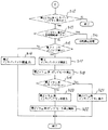
【図4】図1における多色孔版印刷装置のインキ供給制御周りの制御構成を示すブロック図である。
【図5】図1における多色孔版印刷装置のインキパックインキなし解除処理のフローチャートである。
【図6】図5のフローチャートの続きである。
【図7】(a)〜(e)は、従来の多色孔版印刷装置におけるインキパックの交換順序を説明するための説明図である。
【符号の説明】
1 インキ無し検知手段(インキ有無検知手段)としてのインキ有無検知センサ
3a,3b インキ容器としてのインキパック
10a,10b ポンプ駆動手段としてのポンプモータ
11a,11b インキポンプ
14 開閉部材としての前ドア
15a,15b インキ容器着脱用開閉部材としてのインキパックドア
17a 開検知手段(開閉検知手段)としての第1インキパックドアセンサ
17b 開検知手段(開閉検知手段)としての第2インキパックドアセンサ
20a,20b 印刷ドラムユニット
21a 印刷ドラムとしての第1ドラム
21b 印刷ドラムとしての第2ドラム
29a,29b インキ供給装置
30 制御手段、報知制御手段および印刷停止制御手段としての制御装置
31 CPU
34 計時手段としてのタイマ
40 操作パネル
49 報知手段(表示手段)としての液晶表示部[0001]
BACKGROUND OF THE INVENTION
The present invention Stencil printing machine In more detail, stencil printing equipment In place The present invention relates to an ink supply device and an ink supply control device.
[0002]
[Prior art]
Conventionally, a stencil printing method using a stencil printing apparatus is known as a simpler printing method. This means that a master punched and made on the basis of image information is wound around the outer peripheral surface of a porous cylindrical printing drum, also called a plate cylinder, and pressing means such as a press roller against the master on the printing drum Press the printing paper continuously and drive the ink pump to supply ink from the ink container to the ink reservoir provided inside the printing drum, and then supply it from the ink reservoir to the ink supply member such as an ink roller. The printing image is formed by passing the ink from the opening portion of the printing drum and the punching portion of the master and transferring it to the printing paper.
In a single-color stencil printing apparatus having a single printing drum and performing only single-color printing, a multi-color stencil printing apparatus having a plurality of printing drums and capable of multi-color printing, etc., printing paper and master In many cases, a printing drum unit that can be attached to and detached from the printing apparatus main body is configured in order to perform jam processing or color change. The ink container is usually set inside or outside the printing drum constituting the printing drum unit, that is, on the printing drum unit itself.
[0003]
As an example of the configuration around the ink supply device for supplying ink to each printing drum of the multicolor stencil printing machine provided with such a plurality of printing drum units, for example, FIG. An example of borrowing a printing drum (shown as one printing drum) and performing two-color printing using two printing drums is given.
Hereinafter, the problems of the conventional example will be described with reference to FIG. 7 by borrowing FIG. 1, FIG. 2 and FIG. In FIG. 1 and FIG. 2 to be borrowed,
[0004]
As shown in FIG. 4, one
[0005]
The
[0006]
The printing drum unit 20b includes, for example, an ink pack tray 4b that detachably supports an
[0007]
In this example, the
The arrangement positions of the
[0008]
In FIG. 4, when the ink presence / absence detection sensor 1a detects the absence of ink in the ink reservoir 27a through the ink detection needle 2a during printing or at the start of plate making before printing starts, the pump motor 10a starts operating. By turning on the ink pump 11a, the ink pump 11a starts pumping. As a result, the ink is sucked and pumped out from the
During printing, even if the ink pump 11a operates for a certain period of time after the ink presence / absence detection sensor 1a detects the absence of ink in the ink reservoir 27a (or even if the pumping frequency of the ink pump 11a reaches a certain number). When the ink presence / absence detection sensor 1a does not detect the presence of ink in the ink reservoir 27a, it detects that the ink reservoir 27a is out of ink (that is, the
[0009]
Here, the amount of ink in the ink reservoir 27a when the ink presence / absence detection sensor 1a detects that the ink reservoir 27a is out of ink during printing or at the start of printing before printing starts is determined by the ink reservoir 27a. It is not set to detect in a state where there is no ink in the wedge-shaped space to be formed, and even if there is no ink in the
[0010]
When the absence of ink in the
[0011]
The procedure for replacing the
[0012]
When the
[0013]
The control device stops the printing operation based on the door open signal from the door sensor, and enables the printing operation based on the door closing signal from the door sensor and after completion of a predetermined operation after mounting the
[0014]
Next, as shown in FIG. 7B to FIG. 7D, the emptied
[0015]
[Problems to be solved by the invention]
However, when the
In particular, in the case of the multicolor stencil printing apparatus as described above, since there are a plurality of printing drums, there are a plurality of ink packs. During printing, when any of the plurality of ink packs or at random detection of no ink, the printing operation is stopped for ink pack replacement and ink supply.
In addition, when it is detected that the ink packs on both printing drums are out of ink, it is not possible to replace multiple ink packs at the same time. Each time the pack runs out of ink, the printing operation stops and printing is interrupted.
[0016]
It is obvious that the above-described problems may occur in the same manner to some extent even in a single color stencil printing apparatus configured with only one of the
[0017]
Accordingly, the present invention has been made in view of the above-described circumstances, and an object of the present invention is to provide a plurality of colors having a plurality of printing drums and corresponding ink packs (ink containers). Stencil printing machine Or single color Stencil printing machine Regardless of whether the ink pack is out of ink, the ink pack can be replaced without interrupting printing without stopping the printing operation for ink pack replacement and ink replenishment. Stencil printing machine Is to eliminate the waste of time.
[0018]
[Means for Solving the Problems]
In order to solve the above-described problems and achieve the above object, the present invention is characterized in that the invention according to each claim adopts the following configuration.
The invention according to claim 1 is provided in the printing apparatus main body, using an ink container receiving base that detachably supports an ink container containing ink, and ink of the ink container mounted on the ink container receiving base. A printing drum for performing printing; and an opening / closing member provided on the printing apparatus main body so as to be openable and closable so as to cover the ink container cradle and the printing drum. Stencil printing machine The ink container can be attached and detached without opening the opening and closing member, and the ink container attaching and detaching opening and closing member that is openable and closable with respect to the printing apparatus main body, and the ink absence detecting means for detecting the ink absence state of the ink container And an open detection means for detecting an open state of the ink container attaching / detaching opening / closing member, and even if the ink container attaching / detaching member is opened / closed during printing, the ink absence detecting means Control means for prohibiting the stop of the printing operation on the basis of the no ink signal and the open signal from the open detecting means.
Here, as a printing method for performing printing using a printing drum, as in an embodiment described later, a printing drum having at least a support cylindrical body formed of a printing ink-permeable metal thin plate layer is used. On the other hand, a pressing roller (pressing member) or a pressure drum having a diameter substantially the same as the outer diameter of the printing drum provided with a pressing roller or a holding means for holding the leading end of the fed printing paper, or the outside of the printing drum. A pressing unit approaching / separating method in which printing is performed by relatively pressing printing paper against a double cylinder larger than the diameter, and a printing drum contacting / separating method in which printing is performed by pressing the printing drum against the pressing unit via a master plate-making There are methods and their combined methods. As the printing drum contact / separation method, a known one that performs printing by moving the printing drum to the pressing means side (including a type in which an ink supply roller or the like inside the printing drum protrudes to the impression cylinder side) is included.
As the printing drum contact / separation method, for example, a metal screen as disclosed in JP-A-1-204781, JP-A-3-197078 or JP-A-3-254984 is directed from the inside to the outside. A so-called intermediate pressing roller system (including an ink supply roller) is used.
In addition, as the “no ink detection means for detecting the absence of ink in the ink container”, in addition to the no ink detection means as written, it is used in the embodiments described later and general stencil printing devices as an alternative. An ink out detecting means for detecting the ink out condition of the ink reservoir as the ink storing portion formed in the printing drum may be used. The present invention is not limited to this, and an ink amount detecting means for detecting the amount of ink supplied to the printing drum may be used regardless of whether ink is supplied from the inside or outside of the printing drum. This is because this ink amount detection means also detects the ink absence state to be supplied to the printing drum, that is, the ink absence state in the ink container, by detecting the ink amount.
[0019]
Here, as a printing method for performing printing using a printing drum, as in an embodiment described later, a printing drum having at least a support cylindrical body formed of a printing ink-permeable metal thin plate layer is used. On the other hand, a pressing roller (pressing member) or a pressure drum having a diameter substantially the same as the outer diameter of the printing drum provided with a pressing roller or a holding means for holding the leading end of the fed printing paper, or the outside of the printing drum. A pressing unit approaching / separating method in which printing is performed by relatively pressing printing paper against a double cylinder larger than the diameter, and a printing drum contacting / separating method in which printing is performed by pressing the printing drum against the pressing unit via a master plate-making There are methods and their combined methods. As the printing drum contact / separation method, a known one that performs printing by moving the printing drum to the pressing means side (including a type in which an ink supply roller or the like inside the printing drum protrudes to the impression cylinder side) is included.
As the printing drum contact / separation method, for example, a metal screen as disclosed in JP-A-1-204781, JP-A-3-197078 or JP-A-3-254984 is directed from the inside to the outside. A so-called intermediate pressing roller system (including an ink supply roller) is used.
[0020]
The invention described in
[0021]
According to a third aspect of the present invention, there is provided the printing apparatus according to the first or second aspect, wherein the ink absence detecting means for detecting an ink outage state of the ink container and an opening state for detecting the open state of the ink container attaching / detaching member. Even if the ink container attachment / detachment opening / closing member is opened and the ink container is attached / detached during printing, the detection means and the ink absence signal from the ink absence detection means and the open signal from the opening detection means And a control means for prohibiting the stop of the printing operation.
Here, as the “no ink detection means for detecting the ink out condition of the ink container”, in addition to the no ink detection means as described in the text, as an alternative to this, in the embodiment described later and a general stencil printing apparatus, etc. You may use the ink absence detection means which detects the ink absence state of the ink reservoir as an ink storage part formed in the employ | adopted printing drum. The present invention is not limited to this, and an ink amount detecting means for detecting the amount of ink supplied to the printing drum may be used regardless of whether ink is supplied from the inside or outside of the printing drum. This is because this ink amount detection means also detects the ink absence state to be supplied to the printing drum, that is, the ink absence state in the ink container, by detecting the ink amount.
[0022]
The invention described in
[0023]
The invention according to
[0024]
The notification means includes display means for displaying and notifying, and means for notifying by sound or voice. As a specific example of the display means, there is a liquid crystal display unit adopted in an embodiment described later, and as a means for notifying by sound or voice, for example, there is a buzzer. Therefore, as the notification means, an appropriate means may be selected according to the purpose and application, or a combination thereof may be used.
Similarly, as a subordinate concept of the open detection means, in addition to detecting the open state of the ink container attaching / detaching opening / closing member, there is an open / close detecting means for detecting the closed state of the ink container attaching / detaching opening / closing member.
[0025]
The invention according to
As a subordinate concept of the notification duration, there is a display duration.
Specific examples of the control means according to
[0026]
A sixth aspect of the present invention is according to any one of the first to fifth aspects. Stencil printing machine And a plurality of the printing drums.
[0028]
DETAILED DESCRIPTION OF THE INVENTION
Hereinafter, embodiments of the present invention including examples will be described with reference to the drawings (hereinafter simply referred to as “embodiments”). Constituent elements (members and constituent parts) having the same functions and shapes in the conventional example and each embodiment described above are denoted by the same reference numerals, and description thereof is omitted as much as possible. In the figure, components that are configured in a pair and do not need to be specifically distinguished and described are described by appropriately describing one of them for the sake of simplification of description. In order to simplify the drawings and the description, even if the components are to be represented in the drawings, the components that do not need to be specifically described in the drawings may be omitted as appropriate.
[0029]
An embodiment will be described with reference to FIGS. 1 to 6.
1 and 2,
[0030]
First, with reference to FIGS. 1 to 3, the entire structure of the multicolor
As shown in FIGS. 1 and 2, the multicolor
[0031]
In FIGS. 1 and 2,
[0032]
The
One side portion of the
[0033]
The
[0034]
As shown in FIG. 3, each
[0035]
When the
[0036]
As shown in FIGS. 1, 2 and 4, the
[0037]
The
The support cylindrical body has a printable area in which the aperture is formed over a predetermined range on the circumference except the periphery of the
The
[0038]
The
[0039]
The ink roller 25a is formed of a metal such as aluminum or stainless steel or rubber, and rotates in the clockwise direction together with the
[0040]
Next, an ink supply device that supplies ink from the ink packs 3a and 3b mounted on the
As shown in FIG. 4, the
[0041]
In addition to the ink roller 25a, doctor roller 26a, and
In FIG. 4, the configuration around the
[0042]
The pump motor 10a is a DC motor. An electrical connector (not shown) for electrical connection and coupling to the input side of the pump motor 10a is attached to the outer surface of the rear frame. On the printing apparatus
[0043]
Accordingly, when the pump motor 10a is turned on and rotated, the disk and the pin rotate, and this rotational motion is converted into the rocking motion of the link. By being converted into a reciprocating motion in the vertical direction indicated by an arrow in the drawing, the ink in the
[0044]
Next, an
The
[0045]
The liquid
[0046]
Next, the control configuration of the present embodiment including the ink supply control configuration will be described with reference to FIG.
The ink presence / absence detection sensor 1a is fixed to the upper portion of the rear frame provided on the back side of the sheet in FIG. An ink detection needle 2a for detecting the ink amount of the ink reservoir 27a is electrically connected to the input side of the ink presence / absence detection sensor 1a in an electrostatic capacity type. 2a is included.
For example, the ink presence / absence detection sensor 1a has the same configuration as the ink sensor 54 disclosed in, for example, FIG. 4 of JP-A-5-229243. That is, the ink presence / absence detection sensor 1a is triggered by a reference signal generation circuit (not shown) that generates a pulse signal having a predetermined pulse interval, and a fall (or rise) of an output pulse signal of the reference signal generation circuit. And a monostable circuit (not shown) for generating a pulse signal having a detection pulse width in response to the capacitance detected by the ink detection needle 2a, and each of the output signals of the reference signal generation circuit and the monostable circuit. It comprises a phase comparison unit (not shown) that performs phase comparison and outputs a binarized signal. As the ink presence / absence detection sensor 1a, one having the configuration disclosed in FIG. 44 of JP-A-6-155585 is preferably used.
[0047]
The ink detection needle 2a is electrically insulated and held through a support plate (not shown) suspended from the center of the
The ink presence / absence detection means is not limited to the ink presence / absence detection sensor 1a, and the transmission frequency changes due to a change in capacitance, and the presence / absence of ink is detected by detecting this change, or the photoelectric type, etc. It may be.
[0048]
On the outer surface of the rear frame, electrical connectors (not shown) for electrically connecting and coupling the output sides of the ink presence / absence detection sensor 1a and the ink pack presence / absence sensor 12a to a
[0049]
The ink pack presence / absence sensor 12a includes a micro switch and is fixed to a front frame side (not shown). When the
[0050]
In FIG. 4,
[0051]
The
In addition, the
[0052]
First, even when the
[0053]
Second, when the
[0054]
Thirdly, the
[0055]
Fourthly, the
[0056]
Note that the first to fourth control functions of the
[0057]
As drive means to be controlled according to “printing operation” for permitting the continuation of the printing operation or stopping the printing operation, that is, as the controlled object driving means, the
[0058]
The
The
The
[0059]
Next, the operation of the main part will be described with reference to the flowcharts of FIGS. 5 and 6, in order to distinguish the constituent elements of the
[0060]
FIG. 5 shows an operation sequence related to the ink-free releasing process of the ink packs 3a and 3b in the
First, on the
If the
[0061]
Next, the process proceeds to step S <b> 2, and it is determined by the
[0062]
In other words, if the
[0063]
As described above, when the
[0064]
In step S2, if the
In step S4, the
[0065]
In step S4, when the user visually recognizes the no-ink display message on the liquid
[0066]
In step S7, since the
[0067]
Next, when the user opens only the
[0068]
When such an ink pack replacement operation is performed, in step S8, the presence of a
Thereafter, the driving of the pump motor 10a is restarted, and the ink supply operation using the
[0069]
In step S8, when only the
[0070]
Next, the process proceeds to step S12 in FIG. 6, and the ink pack ink no ink release process is performed on the printing drum unit 20b side of the multicolor
In step S12, when the ink out display of the
[0071]
Next, the process proceeds to step S13, and the
[0072]
In other words, if the
[0073]
As described above, when the
[0074]
In step S13, the display continuation time is within a certain period of time before the non-ink display on the liquid
In step S15, the
[0075]
In step S15, when the user visually recognizes the no-ink display message on the liquid
[0076]
In step S18, since the
[0077]
Next, the user does not open the
Thereafter, the driving of the pump motor 10b is resumed, and the ink supply operation using the
[0078]
In step S19, when only the
[0079]
According to the present embodiment, multicolor having two
[0080]
In the above-described embodiment, multicolor having two
[0081]
In the above-described embodiment, multicolor having two
As the number of installed printing drum units and printing drums increases, the frequency at which any of the plurality of ink packs is randomly detected as having no ink during printing during printing is inevitably increased. The effect of eliminating waste of time without stopping the printing operation for replacement and ink replenishment is further enhanced. 6 reference).
[0082]
According to the present invention Stencil printing machine Is a type of supplying ink to the
[0083]
According to the present invention Stencil printing machine Is not limited to the multi-color stencil printing apparatus of the above-described embodiment, and instead of a printing drum configured to be detachable with respect to the printing apparatus main body, printing is performed only on one type of printing paper such as a paper size A4 plate, for example. It can also be applied to a so-called A4 plate dedicated machine having a printing drum that is manufactured for the purpose of carrying out the above and is mounted and fixed to the printing apparatus main body.
[0085]
As described above, the present invention has been described with respect to specific embodiments and examples included therein, but the configuration of the present invention is not limited to the above-described configuration, Alternatively, it may be configured independently, and it is apparent to those skilled in the art that various embodiments and examples can be configured within the scope of the present invention in accordance with the necessity, purpose and application.
[0086]
【The invention's effect】
As described above, according to the present invention, the conventional technology as described above is used. Stencil printing machine Solve new problems and Stencil printing machine Can be provided. The effects for each claim are as follows.
According to the first aspect of the present invention, the ink container can be attached and detached without opening or closing the opening and closing member provided on the printing apparatus main body so as to cover the ink container cradle and the printing drum. Since it has a flexible ink container attachment / detachment member, it is possible to replace the ink container without interrupting printing without stopping the printing operation for ink container replacement and ink replenishment. Ink replenishment operations and troublesome operations such as resuming printing by pressing the print key are also eliminated, so that it is possible to eliminate the waste of time that the printing operation stops even when printing is in a hurry. In addition, during the printing, the control means opens the ink container attaching / detaching member and opens / closes the ink container. The printing operation is prohibited based on the signal and the opening signal from the opening detection means, so that when the ink container is detected to be out of ink, the printing operation is stopped for ink container replacement and ink replenishment. In addition, the ink container can be replaced without interrupting the printing, thereby eliminating the waste of time that the printing operation is stopped.
[0087]
According to the invention described in
[0089]
[0090]
[0091]
[0092]
Claim 6 According to the described invention, claims 1 to 5 In addition to the effect of the invention described in any one of the above, during printing, the frequency with which any of the ink containers arranged corresponding to the plurality of printing drums is randomly detected as having no ink is inevitably detected. Therefore, the effect of eliminating waste of time without stopping the printing operation for ink pack replacement and ink replenishment is further enhanced.
[Brief description of the drawings]
FIG. 1 is a perspective view of a multicolor stencil printing apparatus showing an embodiment of the present invention.
2 is a perspective view showing an arrangement state of a print drum unit and an ink pack door in a state where a front door of the multicolor stencil printing apparatus in FIG. 1 is opened. FIG.
3 is a plan view of a main part showing an arrangement example of an ink pack door sensor for detecting an open / closed state of the ink pack door of the multicolor stencil printing apparatus in FIG. 1. FIG.
4 is a block diagram showing a control configuration around ink supply control of the multicolor stencil printing apparatus in FIG. 1; FIG.
5 is a flowchart of an ink pack ink no-release process of the multicolor stencil printing apparatus in FIG. 1. FIG.
6 is a continuation of the flowchart of FIG.
FIGS. 7A to 7E are explanatory views for explaining an ink pack replacement order in a conventional multicolor stencil printing apparatus. FIGS.
[Explanation of symbols]
1 Ink presence / absence detection sensor as ink absence detection means (ink presence / absence detection means)
3a, 3b Ink pack as ink container
10a, 10b Pump motor as pump drive means
11a, 11b Ink pump
14 Front door as opening and closing member
15a, 15b Ink pack door as opening / closing member for attaching / detaching ink container
17a Open detection means (open / close detection means) 1st ink pack door sensor as
17b Open detection means (open / close detection means) As a second ink pack door sensor
20a, 20b Printing drum unit
21a First drum as printing drum
21b Second drum as printing drum
29a, 29b Ink supply device
30. Control device as control means, notification control means and printing stop control means
31 CPU
34 As a timekeeping means Timer
40 Operation panel
49 Liquid crystal display section as notification means (display means)
Claims (6)
前記開閉部材を開けることなく前記インキ容器の着脱を行える、前記印刷装置本体に対して開閉自在なインキ容器着脱用開閉部材と、
前記インキ容器のインキの無し状態を検知するインキ無し検知手段と、
前記インキ容器着脱用開閉部材の開状態を検知する開検知手段と、
印刷中に、前記インキ容器着脱用開閉部材を開けて前記インキ容器の着脱をしても、前記インキ無し検知手段からのインキ無し信号および前記開検知手段からの開信号に基づいて、印刷動作の停止を禁止させる制御手段と、
を有することを特徴とする孔版印刷装置。An ink container pedestal provided in the printing apparatus main body and detachably supporting an ink container containing ink; a printing drum that performs printing using the ink of the ink container mounted on the ink container pedestal; In a stencil printing apparatus having an ink container cradle and an opening / closing member provided on the printing apparatus main body so as to be openable and closable so as to cover the printing drum,
An ink container attachment / detachment opening / closing member that can be attached / detached to / from the printing apparatus main body, and that can be attached / detached without opening the opening / closing member;
No ink detection means for detecting the absence of ink in the ink container;
An open detection means for detecting an open state of the ink container attaching / detaching opening and closing member;
During printing, even if the ink container attaching / detaching member is opened and the ink container is attached / detached, the printing operation is performed based on the no-ink signal from the no-ink detecting means and the open signal from the open detecting means. Control means for prohibiting the stop,
A stencil printing apparatus comprising:
前記インキ容器着脱用開閉部材を前記開閉部材に設けたことを特徴とする孔版印刷装置。The stencil printing apparatus according to claim 1,
A stencil printing apparatus, wherein the ink container attaching / detaching member is provided on the opening / closing member.
前記印刷ドラムにインキを供給するインキポンプと、
前記インキポンプを駆動するポンプ駆動手段と、
を有し、
前記制御手段は、前記印刷中に、前記インキ容器着脱用開閉部材を開けたとき、前記開検知手段からの開信号に基づいて、前記インキポンプの駆動を停止するように前記ポンプ駆動手段を制御することを特徴とする孔版印刷装置。In the stencil printing apparatus according to claim 1 or 2,
An ink pump for supplying ink to the printing drum;
Pump driving means for driving the ink pump;
Have
The control means controls the pump driving means to stop driving the ink pump based on an open signal from the opening detection means when the ink container attaching / detaching opening / closing member is opened during the printing. A stencil printing apparatus .
前記インキ容器のインキ無し状態を報知する報知手段と、
前記インキ無し検知手段からのインキ無し信号に基づいて、インキ無し状態を報知するように前記報知手段を制御する報知制御手段と、
を有することを特徴とする孔版印刷装置。In the stencil printing apparatus according to claim 1 or 2,
Informing means for informing the ink container of the ink out condition,
Based on the no ink signal from the no ink detection means, a notification control means for controlling the notification means so as to notify the ink out condition;
A stencil printing apparatus comprising:
前記インキ容器のインキ無し状態を報知している間の報知継続時間を計時する計時手段と、
前記報知継続時間が一定時間経過しても、前記インキ容器着脱用開閉部材を開けて前記インキ容器の着脱が行われないとき、前記計時手段からの報知継続時間信号および前記開検知手段からの開信号に基づいて、印刷動作を停止させる印刷停止制御手段と、
を有することを特徴とする孔版印刷装置。In the stencil printing apparatus according to claim 4,
A time measuring means for measuring a notification continuation time while notifying the ink-out state of the ink container;
When the ink container attachment / detachment opening / closing member is opened and the ink container is not attached / detached even when the notification continuation time has elapsed, the notification continuation time signal from the time measuring means and the opening detection means from the opening detection means. Printing stop control means for stopping the printing operation based on the signal;
A stencil printing apparatus comprising:
前記印刷ドラムを複数有することを特徴とする孔版印刷装置。In the stencil printing apparatus according to any one of claims 1 to 5,
A stencil printing apparatus comprising a plurality of the printing drums.
Priority Applications (1)
| Application Number | Priority Date | Filing Date | Title |
|---|---|---|---|
| JP2000275778A JP4672843B2 (en) | 2000-09-12 | 2000-09-12 | Stencil printing machine |
Applications Claiming Priority (1)
| Application Number | Priority Date | Filing Date | Title |
|---|---|---|---|
| JP2000275778A JP4672843B2 (en) | 2000-09-12 | 2000-09-12 | Stencil printing machine |
Publications (2)
| Publication Number | Publication Date |
|---|---|
| JP2002086671A JP2002086671A (en) | 2002-03-26 |
| JP4672843B2 true JP4672843B2 (en) | 2011-04-20 |
Family
ID=18761342
Family Applications (1)
| Application Number | Title | Priority Date | Filing Date |
|---|---|---|---|
| JP2000275778A Expired - Fee Related JP4672843B2 (en) | 2000-09-12 | 2000-09-12 | Stencil printing machine |
Country Status (1)
| Country | Link |
|---|---|
| JP (1) | JP4672843B2 (en) |
Families Citing this family (1)
| Publication number | Priority date | Publication date | Assignee | Title |
|---|---|---|---|---|
| JP4758207B2 (en) * | 2005-11-24 | 2011-08-24 | 東北リコー株式会社 | Stencil printing machine |
Citations (2)
| Publication number | Priority date | Publication date | Assignee | Title |
|---|---|---|---|---|
| JPS55151542U (en) * | 1979-04-17 | 1980-10-31 | ||
| JP2000127600A (en) * | 1998-10-26 | 2000-05-09 | Riso Kagaku Corp | Stencil printing equipment |
-
2000
- 2000-09-12 JP JP2000275778A patent/JP4672843B2/en not_active Expired - Fee Related
Patent Citations (2)
| Publication number | Priority date | Publication date | Assignee | Title |
|---|---|---|---|---|
| JPS55151542U (en) * | 1979-04-17 | 1980-10-31 | ||
| JP2000127600A (en) * | 1998-10-26 | 2000-05-09 | Riso Kagaku Corp | Stencil printing equipment |
Also Published As
| Publication number | Publication date |
|---|---|
| JP2002086671A (en) | 2002-03-26 |
Similar Documents
| Publication | Publication Date | Title |
|---|---|---|
| US5699731A (en) | Ink-supply control device and stencil printing machine having the same | |
| US4846057A (en) | Screen printing machine with waste printing plate discharge means | |
| JP4672843B2 (en) | Stencil printing machine | |
| JP4584414B2 (en) | Master roll and ink container identification method | |
| JP2000203139A (en) | Stencil printer | |
| JP3965056B2 (en) | Printing method and printing apparatus | |
| JP2002086686A (en) | Printing control device, recording medium wherein computer readable program is recorded, and printing system | |
| JP4515577B2 (en) | Double cylinder printer | |
| US6356293B1 (en) | Printer including a plurality of print drums | |
| JP2838222B2 (en) | A device for detecting the remaining amount of ink in an ink container in a stencil printing machine | |
| US7333123B2 (en) | Thermal type image forming apparatus and method of removing jammed medium therefrom | |
| CN207825755U (en) | Small print device simple cap-opening mechanism | |
| JP2004155170A (en) | Printing press | |
| JP2005165061A (en) | Image forming apparatus | |
| JP4712933B2 (en) | Printing method and printing apparatus | |
| JP4138063B2 (en) | Stencil printing machine | |
| CN207998347U (en) | A kind of print copying all-in-one machine | |
| JP2007301747A (en) | Image forming apparatus with accounting function | |
| JPH08183238A (en) | Screen printing machine | |
| JP2001260327A (en) | Stencil printing apparatus | |
| JP4658297B2 (en) | Printing device | |
| JP4275789B2 (en) | Ink supply control device for printing device | |
| JPH0761739B2 (en) | Ink supply control device in printing device | |
| JPH0541027Y2 (en) | ||
| JP4473521B2 (en) | Printer |
Legal Events
| Date | Code | Title | Description |
|---|---|---|---|
| A621 | Written request for application examination |
Free format text: JAPANESE INTERMEDIATE CODE: A621 Effective date: 20070829 |
|
| A977 | Report on retrieval |
Free format text: JAPANESE INTERMEDIATE CODE: A971007 Effective date: 20100528 |
|
| A131 | Notification of reasons for refusal |
Free format text: JAPANESE INTERMEDIATE CODE: A131 Effective date: 20100608 |
|
| A521 | Written amendment |
Free format text: JAPANESE INTERMEDIATE CODE: A523 Effective date: 20100804 |
|
| A131 | Notification of reasons for refusal |
Free format text: JAPANESE INTERMEDIATE CODE: A131 Effective date: 20100907 |
|
| A521 | Written amendment |
Free format text: JAPANESE INTERMEDIATE CODE: A523 Effective date: 20101029 |
|
| TRDD | Decision of grant or rejection written | ||
| A01 | Written decision to grant a patent or to grant a registration (utility model) |
Free format text: JAPANESE INTERMEDIATE CODE: A01 Effective date: 20110111 |
|
| A01 | Written decision to grant a patent or to grant a registration (utility model) |
Free format text: JAPANESE INTERMEDIATE CODE: A01 |
|
| A61 | First payment of annual fees (during grant procedure) |
Free format text: JAPANESE INTERMEDIATE CODE: A61 Effective date: 20110120 |
|
| R150 | Certificate of patent or registration of utility model |
Free format text: JAPANESE INTERMEDIATE CODE: R150 |
|
| FPAY | Renewal fee payment (event date is renewal date of database) |
Free format text: PAYMENT UNTIL: 20140128 Year of fee payment: 3 |
|
| LAPS | Cancellation because of no payment of annual fees |