JP4671692B2 - Automotive internal combustion engine - Google Patents
Automotive internal combustion engine Download PDFInfo
- Publication number
- JP4671692B2 JP4671692B2 JP2004558953A JP2004558953A JP4671692B2 JP 4671692 B2 JP4671692 B2 JP 4671692B2 JP 2004558953 A JP2004558953 A JP 2004558953A JP 2004558953 A JP2004558953 A JP 2004558953A JP 4671692 B2 JP4671692 B2 JP 4671692B2
- Authority
- JP
- Japan
- Prior art keywords
- engine
- torque
- output torque
- internal combustion
- control unit
- Prior art date
- Legal status (The legal status is an assumption and is not a legal conclusion. Google has not performed a legal analysis and makes no representation as to the accuracy of the status listed.)
- Expired - Fee Related
Links
Images
Classifications
-
- F—MECHANICAL ENGINEERING; LIGHTING; HEATING; WEAPONS; BLASTING
- F16—ENGINEERING ELEMENTS AND UNITS; GENERAL MEASURES FOR PRODUCING AND MAINTAINING EFFECTIVE FUNCTIONING OF MACHINES OR INSTALLATIONS; THERMAL INSULATION IN GENERAL
- F16H—GEARING
- F16H59/00—Control inputs to control units of change-speed-, or reversing-gearings for conveying rotary motion
- F16H59/14—Inputs being a function of torque or torque demand
- F16H59/16—Dynamometric measurement of torque
-
- B—PERFORMING OPERATIONS; TRANSPORTING
- B60—VEHICLES IN GENERAL
- B60W—CONJOINT CONTROL OF VEHICLE SUB-UNITS OF DIFFERENT TYPE OR DIFFERENT FUNCTION; CONTROL SYSTEMS SPECIALLY ADAPTED FOR HYBRID VEHICLES; ROAD VEHICLE DRIVE CONTROL SYSTEMS FOR PURPOSES NOT RELATED TO THE CONTROL OF A PARTICULAR SUB-UNIT
- B60W10/00—Conjoint control of vehicle sub-units of different type or different function
- B60W10/04—Conjoint control of vehicle sub-units of different type or different function including control of propulsion units
- B60W10/06—Conjoint control of vehicle sub-units of different type or different function including control of propulsion units including control of combustion engines
-
- B—PERFORMING OPERATIONS; TRANSPORTING
- B60—VEHICLES IN GENERAL
- B60W—CONJOINT CONTROL OF VEHICLE SUB-UNITS OF DIFFERENT TYPE OR DIFFERENT FUNCTION; CONTROL SYSTEMS SPECIALLY ADAPTED FOR HYBRID VEHICLES; ROAD VEHICLE DRIVE CONTROL SYSTEMS FOR PURPOSES NOT RELATED TO THE CONTROL OF A PARTICULAR SUB-UNIT
- B60W10/00—Conjoint control of vehicle sub-units of different type or different function
- B60W10/10—Conjoint control of vehicle sub-units of different type or different function including control of change-speed gearings
- B60W10/11—Stepped gearings
-
- B—PERFORMING OPERATIONS; TRANSPORTING
- B60—VEHICLES IN GENERAL
- B60W—CONJOINT CONTROL OF VEHICLE SUB-UNITS OF DIFFERENT TYPE OR DIFFERENT FUNCTION; CONTROL SYSTEMS SPECIALLY ADAPTED FOR HYBRID VEHICLES; ROAD VEHICLE DRIVE CONTROL SYSTEMS FOR PURPOSES NOT RELATED TO THE CONTROL OF A PARTICULAR SUB-UNIT
- B60W30/00—Purposes of road vehicle drive control systems not related to the control of a particular sub-unit, e.g. of systems using conjoint control of vehicle sub-units, or advanced driver assistance systems for ensuring comfort, stability and safety or drive control systems for propelling or retarding the vehicle
- B60W30/18—Propelling the vehicle
-
- B—PERFORMING OPERATIONS; TRANSPORTING
- B60—VEHICLES IN GENERAL
- B60W—CONJOINT CONTROL OF VEHICLE SUB-UNITS OF DIFFERENT TYPE OR DIFFERENT FUNCTION; CONTROL SYSTEMS SPECIALLY ADAPTED FOR HYBRID VEHICLES; ROAD VEHICLE DRIVE CONTROL SYSTEMS FOR PURPOSES NOT RELATED TO THE CONTROL OF A PARTICULAR SUB-UNIT
- B60W2510/00—Input parameters relating to a particular sub-units
- B60W2510/06—Combustion engines, Gas turbines
- B60W2510/0614—Position of fuel or air injector
- B60W2510/0623—Fuel flow rate
-
- B—PERFORMING OPERATIONS; TRANSPORTING
- B60—VEHICLES IN GENERAL
- B60W—CONJOINT CONTROL OF VEHICLE SUB-UNITS OF DIFFERENT TYPE OR DIFFERENT FUNCTION; CONTROL SYSTEMS SPECIALLY ADAPTED FOR HYBRID VEHICLES; ROAD VEHICLE DRIVE CONTROL SYSTEMS FOR PURPOSES NOT RELATED TO THE CONTROL OF A PARTICULAR SUB-UNIT
- B60W2510/00—Input parameters relating to a particular sub-units
- B60W2510/06—Combustion engines, Gas turbines
- B60W2510/0657—Engine torque
-
- B—PERFORMING OPERATIONS; TRANSPORTING
- B60—VEHICLES IN GENERAL
- B60W—CONJOINT CONTROL OF VEHICLE SUB-UNITS OF DIFFERENT TYPE OR DIFFERENT FUNCTION; CONTROL SYSTEMS SPECIALLY ADAPTED FOR HYBRID VEHICLES; ROAD VEHICLE DRIVE CONTROL SYSTEMS FOR PURPOSES NOT RELATED TO THE CONTROL OF A PARTICULAR SUB-UNIT
- B60W2540/00—Input parameters relating to occupants
- B60W2540/10—Accelerator pedal position
-
- B—PERFORMING OPERATIONS; TRANSPORTING
- B60—VEHICLES IN GENERAL
- B60W—CONJOINT CONTROL OF VEHICLE SUB-UNITS OF DIFFERENT TYPE OR DIFFERENT FUNCTION; CONTROL SYSTEMS SPECIALLY ADAPTED FOR HYBRID VEHICLES; ROAD VEHICLE DRIVE CONTROL SYSTEMS FOR PURPOSES NOT RELATED TO THE CONTROL OF A PARTICULAR SUB-UNIT
- B60W2552/00—Input parameters relating to infrastructure
-
- F—MECHANICAL ENGINEERING; LIGHTING; HEATING; WEAPONS; BLASTING
- F16—ENGINEERING ELEMENTS AND UNITS; GENERAL MEASURES FOR PRODUCING AND MAINTAINING EFFECTIVE FUNCTIONING OF MACHINES OR INSTALLATIONS; THERMAL INSULATION IN GENERAL
- F16H—GEARING
- F16H59/00—Control inputs to control units of change-speed-, or reversing-gearings for conveying rotary motion
- F16H59/14—Inputs being a function of torque or torque demand
- F16H2059/142—Inputs being a function of torque or torque demand of driving resistance calculated from weight, slope, or the like
-
- F—MECHANICAL ENGINEERING; LIGHTING; HEATING; WEAPONS; BLASTING
- F16—ENGINEERING ELEMENTS AND UNITS; GENERAL MEASURES FOR PRODUCING AND MAINTAINING EFFECTIVE FUNCTIONING OF MACHINES OR INSTALLATIONS; THERMAL INSULATION IN GENERAL
- F16H—GEARING
- F16H59/00—Control inputs to control units of change-speed-, or reversing-gearings for conveying rotary motion
- F16H59/36—Inputs being a function of speed
- F16H59/44—Inputs being a function of speed dependent on machine speed of the machine, e.g. the vehicle
-
- F—MECHANICAL ENGINEERING; LIGHTING; HEATING; WEAPONS; BLASTING
- F16—ENGINEERING ELEMENTS AND UNITS; GENERAL MEASURES FOR PRODUCING AND MAINTAINING EFFECTIVE FUNCTIONING OF MACHINES OR INSTALLATIONS; THERMAL INSULATION IN GENERAL
- F16H—GEARING
- F16H61/00—Control functions within control units of change-speed- or reversing-gearings for conveying rotary motion ; Control of exclusively fluid gearing, friction gearing, gearings with endless flexible members or other particular types of gearing
- F16H61/02—Control functions within control units of change-speed- or reversing-gearings for conveying rotary motion ; Control of exclusively fluid gearing, friction gearing, gearings with endless flexible members or other particular types of gearing characterised by the signals used
- F16H61/0202—Control functions within control units of change-speed- or reversing-gearings for conveying rotary motion ; Control of exclusively fluid gearing, friction gearing, gearings with endless flexible members or other particular types of gearing characterised by the signals used the signals being electric
- F16H61/0204—Control functions within control units of change-speed- or reversing-gearings for conveying rotary motion ; Control of exclusively fluid gearing, friction gearing, gearings with endless flexible members or other particular types of gearing characterised by the signals used the signals being electric for gearshift control, e.g. control functions for performing shifting or generation of shift signal
- F16H61/0213—Control functions within control units of change-speed- or reversing-gearings for conveying rotary motion ; Control of exclusively fluid gearing, friction gearing, gearings with endless flexible members or other particular types of gearing characterised by the signals used the signals being electric for gearshift control, e.g. control functions for performing shifting or generation of shift signal characterised by the method for generating shift signals
Abstract
Description
本発明は、自動車用内燃機関において、運転者により要求されるとともに少なくともエンジンの燃焼室内に噴射される燃料量を表す信号によってエンジンの出力トルクを制御する記憶機能を持つ電子制御部材を有する内燃機関に関する。 The present invention relates to an internal combustion engine having an electronic control member having a memory function for controlling an output torque of the engine by a signal which is required by a driver and represents at least the amount of fuel injected into the combustion chamber of the engine. About.
内燃機関のトルクおよび回転数の制御と、関連ある自動変速ギヤボックスにおけるギヤシフトの制御とのために、一般に、運転者(アクセル位置)により要求される燃料量、エンジン速度、ギヤボックスの入力軸における回転数および走行速度を含む異なるエンジンおよび自動車データを表すさまざまな信号の送信を受けるとともに、多数の調整要素、たとえばサーボモータを用いてエンジン速度とギヤボックスにおけるギヤシフトとを正確に調整するマイクロプロセッサの形態をとる制御部材を用いることが一般に知られている。 For the control of the torque and speed of the internal combustion engine and the control of the gear shift in the relevant automatic transmission gearbox, in general, the amount of fuel required by the driver (accelerator position), the engine speed, the gearbox input shaft A microprocessor that receives various signals representing different engine and vehicle data, including speed and travel speed, and uses a number of adjustment elements, such as servo motors, to accurately adjust engine speed and gear shift in the gearbox. It is generally known to use a control member that takes the form.
本発明の目的は、冒頭部分に記載の種類の内燃機関において、エンジンのトルク性能を常に診断して、エンジンがアクセルレバーに対応するトルクを供給できなくなる原因となる欠陥を有するかどうか、たとえば、エンジンは、吸気マニホルドにおける漏れのために過度に低いトルクを供給しているか、または給気圧力調整不良の結果として過度に高い給気圧力を、以って過度に高いトルクを生じしめているかを発見することを可能にする内燃機関を創出することにある。 The object of the present invention is, in an internal combustion engine of the kind described in the opening part, to constantly diagnose the torque performance of the engine and to determine whether it has a defect that causes the engine to be unable to supply the torque corresponding to the accelerator lever, for example, The engine discovers whether it is supplying too low torque due to a leak in the intake manifold, or is causing excessively high charge pressure as a result of supply pressure misalignment, resulting in excessively high torque It is to create an internal combustion engine that makes it possible.
これは、本発明にしたがって、異なる回転速度におけるエンジンの基準値を制御部材の記憶装置に記憶させることと、エンジンのクランク軸から現在の出力トルクを検出するとともに、前記制御部材に前記現在の出力トルクを表す信号を送信するトルク送信機を配設することと、前記制御部材を、前記トルク送信機により検出される現在のトルクを常に記録するとともに問題の回転速度における前記記憶された基準値と比較し、かつ前記基準値と前記検出された現在値との間における不一致に関する情報を記憶するように構成することとによって達成される。 According to the present invention, the engine reference value at different rotational speeds is stored in the storage device of the control member, the current output torque is detected from the crankshaft of the engine, and the current output is output to the control member. Providing a torque transmitter for transmitting a signal representative of torque, the control member constantly recording the current torque detected by the torque transmitter and the stored reference value at the rotational speed in question; And comparing and storing information relating to the discrepancy between the reference value and the detected current value.
好ましくは、本発明にしたがった前記エンジン診断機能は、エンジン制御機能とは別に、さらに変速制御機能を有するとともに、特許文献1に記載されているように、内燃機関と関連ある自動変速ギヤボックスとを制御するために用いられる制御装置にプログラムされる。現在のエンジントルクは、この場合は、ギヤボックスの入力軸と調和せしめられるトルク送信機から受信される。トルク送信機により検出される入力軸トルクを用いて現在の路面抵抗を計算するとともに、前記計算された路面抵抗に基づいてギヤを選択することとは別に、トルク送信機により検出されるトルクは、この場合は、エンジン診断にも用いられる。 Preferably, the engine diagnosis function according to the present invention has a shift control function in addition to the engine control function, and an automatic transmission gearbox associated with the internal combustion engine as described in Patent Document 1. Programmed into a control device used to control the. The current engine torque is received in this case from a torque transmitter that is harmonized with the gearbox input shaft. Aside from calculating the current road resistance using the input shaft torque detected by the torque transmitter and selecting a gear based on the calculated road resistance, the torque detected by the torque transmitter is: In this case, it is also used for engine diagnosis.
付随するギヤボックスを有する内燃機関の実施例の略図を示す添付図面に示される例証的な実施例を参照して、本発明をより詳細に説明する。 The invention will be described in more detail with reference to an illustrative embodiment shown in the accompanying drawings, which shows a schematic illustration of an embodiment of an internal combustion engine with an associated gearbox.
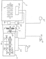
図において、1は、クラッチケース4内に密閉される、一般に3により示される単板乾式クラッチに結合されるクランク軸2を有する6気筒内燃機関、たとえばディーゼル機関を示す。単板乾式クラッチの代わりに、二枚板クラッチが用いられうる。クランク軸2は、クラッチ3のクラッチハウジング5に回転不能に接続される一方で、円板6は、一般に9により示されるギヤボックスのケーシング8内において回転可能に取り付けられる入力軸7に回転不能に接続される。ケーシング8内において、主軸10と中間軸11とが回転可能に取り付けられる。
In the figure, 1 designates a 6-cylinder internal combustion engine, for example a diesel engine, having a crankshaft 2 which is sealed in a clutch case 4 and is coupled to a single plate dry clutch, generally indicated by 3. Instead of the single plate dry clutch, a two plate clutch can be used. The crankshaft 2 is non-rotatably connected to the clutch housing 5 of the clutch 3, while the disc 6 is non-rotatable to an input shaft 7 that is rotatably mounted in a
ギヤボックス9は、特許文献1に図示および説明される種類のものとされ得、内燃機関1とあわせて、ギヤボックス9の構造および作用のより詳細な説明については、前記文献を参照されたい。 The gear box 9 may be of the type illustrated and described in Patent Document 1, and refer to the above document for a more detailed description of the structure and operation of the gear box 9 along with the internal combustion engine 1.
エンジン1は、アクセル21と調和せしめられる送信機22から受信されうる、運転者により要求される燃料量を表す信号によってエンジントルクを調整する記憶機能を有する電子制御装置20により制御される。このエンジン制御装置は、ギヤボックスにおけるギヤシフトを制御する電子変速制御装置23と通信する。変速制御装置23は、燃料噴射量に関する一定の情報を受信するとともに、該噴射量による現在のエンジントルクを記録する。
The engine 1 is controlled by an
変速制御装置23は、さらにまた、ギヤボックスの入力軸7における現在のトルクに関する一定の情報を、本質的に周知であり、かつ従来的に研究所において用いられてきた種類のものとされうる、前記入力軸と調和せしめられるトルク送信機24を介して受信するとともに、前記トルク送信機24からの前記信号を用いて、現在の路面抵抗を計算する。これにより、変速制御装置23は、クラッチ3の前における1個以上のエンジン駆動/エンジン取付け動力点26により駆動される1個以上の補助装置25により影響される、燃料噴射量により計算されるエンジントルクに呼応するのではなしに、実際の路面抵抗に基づいてギヤ選択とギヤシフト時期とを判断する。たとえば油圧ポンプ、冷却ファン、発電機、圧縮空気式コンプレッサまたはACコンプレッサでありうる前記補助装置25は、エンジン制御装置20に接続される手動かつ/または自動制御装置27によって、エンジンの駆動のために接続または接続解除されうる。
The speed
ギヤボックスの入力軸7においてトルク送信機24により検出されるトルクは、本発明にしたがって用いられて、エンジンのトルク性能が診断されて、エンジンが故障してアクセルレバーに対応するトルクを供給していないかどうかが発見される。たとえば、エンジンシリンダへの給気に影響を及ぼす漏れによる「低調化」または過度に高い給気圧力とシリンダへの過剰な給気量とを生じしめる給気圧力調整不良による「激烈化」が感知される。 The torque detected by the torque transmitter 24 at the gearbox input shaft 7 is used in accordance with the present invention to diagnose the torque performance of the engine and supply the torque corresponding to the accelerator lever when the engine fails. Whether or not is discovered. For example, “degradation” due to leakage that affects the supply to the engine cylinder, or “intensification” due to poor supply pressure adjustment that causes excessively high supply pressure and excessive supply to the cylinder. Is done.
この目的のために、異なる回転数におけるエンジントルクの基準値が、本発明にしたがって、エンジン制御装置20において記憶される。これらの基準値は、手動的にプログラム入力される値と、出荷に先立つ、試験運転装置におけるエンジンの試験運転時のエンジン機能測定とによって得られうる。多数の異なる回転数において最大エンジントルクを測定するとともに、これらの測定値を外挿することによって、エンジンの回転速度範囲内におけるエンジンの最大トルク曲線を判断することができ、その後、この最大トルク曲線が制御装置に記憶せしめられる。
For this purpose, engine torque reference values at different rotational speeds are stored in the
変速制御装置23は、エンジン制御装置20を介して(燃料噴射量によって)現在のエンジントルクを、トルク送信機24を介して現在のエンジン速度におけるギヤボックスの入力軸7での現在のトルクを記録する。この情報を補助装置25の状態(接続状態または接続解除状態)に関する情報とあわせて用いて、変速制御装置23は、異なるエンジン速度におけるエンジントルクを計算するとともに、これを基準値と比較して、エンジン性能が正常であるかどうかを判断することができる。正常な性能との不一致が指示される場合は、この不一致が、制御装置に記憶されて、たとえば整備員は、制御装置に測定器を接続すると、性能が正常値を上回るかまたは下回るかどうか、すなわち出力トルクが基準値を上回るかまたは下回るかどうかを判断することができるようになる。正常な性能との不一致が指示される場合は、さらにまた、直接車上、たとえば走行データ表示装置上において制御装置からこのことを報告させることが考えられうる。
The speed
正常な性能との不一致の記録には、当然ながら、エンジンの制動時に、運転者により要求される燃料量が零になりうるため、エンジントルクが負となる不一致の記録も含まれる。基準値との正のトルクの不一致の記録では、1個以上の補助装置25がオン状態にあるかどうかが考慮されるのと全く同様に、負のトルクの記録では、1個以上の補助ブレーキ装置(図示せず)、たとえば圧縮ブレーキまたは排気ブレーキが作動しているかどうかが考慮される。 The discrepancy record with the normal performance naturally includes a discrepancy record in which the engine torque becomes negative because the amount of fuel required by the driver can be zero when the engine is braked. Just as the recording of the positive torque discrepancy with the reference value takes into account whether one or more auxiliary devices 25 are in the on state, the recording of negative torque has one or more auxiliary brakes. It is considered whether a device (not shown), for example a compression brake or an exhaust brake, is activated.
互いに通信する別々のエンジンと変速装置とを有する、図面に示された実施例を参照して、前記に本発明を説明したが、本発明の範囲内において、エンジンおよび変速制御機能は、さらにまた、当然ながら、同じ1個の制御装置に一体化されうる。トルク送信機がギヤシフトの制御に用いられない場合は、トルク送信機をギヤボックスの入力軸と調和させる必要はないが、その代わりに、それが適切である場合は、エンジンのクランク軸と調和せしめられうる。 Although the present invention has been described above with reference to the embodiments shown in the drawings having separate engines and transmissions in communication with each other, within the scope of the present invention, the engine and the shift control function Of course, it can be integrated into the same single control device. If the torque transmitter is not used to control the gearshift, it is not necessary to tune the torque transmitter with the gearbox input shaft, but instead tune it with the engine crankshaft if it is appropriate. Can be.
Claims (4)
前記基準値は、当該自動車に搭載されるエンジンの出荷前に、少なくとも前記エンジンの試験運転時におけるエンジン機能測定により得られた固定の値であり、
前記エンジンが搭載された当該自動車の実走行時において、前記エンジンのクランク軸(2)から現在の出力トルクを検出するとともに、前記現在の出力トルクを表す信号を前記制御部(20、23)に送信するトルク送信機(24)が配設され、前記制御部は、前記トルク送信機により検出される前記現在の出力トルクを常に記録するとともに、問題の回転数における前記記憶された基準値と前記現在の出力トルクとを比較し、該基準値と現在の出力トルクとの比較に基づき前記エンジンの実走行時における現在のエンジン機能が正常であるか非正常であるかを評価し、前記エンジン機能が非正常である評価がされた場合に、前記エンジン機能が非正常である評価情報として記憶するように設計されることを特徴とする内燃機関。An electronic control unit (20, 23) having a storage function that controls the output torque of the engine by a signal that is required by the driver and at least represents the amount of fuel injected into the combustion chamber of the engine mounted on the automobile In an automotive internal combustion engine in which a reference value of engine torque at different rotational speeds is stored in the control unit,
The reference value is a fixed value obtained by measuring an engine function at least during a test operation of the engine before shipment of the engine mounted on the vehicle.
During actual driving of the vehicle on which the engine is mounted, the current output torque is detected from the crankshaft (2) of the engine , and a signal indicating the current output torque is sent to the control unit (20, 23). A transmitting torque transmitter (24) is provided, and the control unit always records the current output torque detected by the torque transmitter, and stores the stored reference value at the rotational speed in question and the comparing the current output torque, to assess whether the non whether the current engine function is normal normal during actual running of the engine based on a comparison between the reference value and the current output torque, the engine functions An internal combustion engine designed to store evaluation information indicating that the engine function is abnormal when the evaluation is abnormal.
Applications Claiming Priority (2)
| Application Number | Priority Date | Filing Date | Title |
|---|---|---|---|
| SE0203674A SE524759C2 (en) | 2002-12-12 | 2002-12-12 | Combustion engine for motor vehicles |
| PCT/SE2003/001864 WO2004052676A1 (en) | 2002-12-12 | 2003-12-01 | Combustion engine for a motor vehicle |
Publications (2)
| Publication Number | Publication Date |
|---|---|
| JP2006509945A JP2006509945A (en) | 2006-03-23 |
| JP4671692B2 true JP4671692B2 (en) | 2011-04-20 |
Family
ID=20289835
Family Applications (1)
| Application Number | Title | Priority Date | Filing Date |
|---|---|---|---|
| JP2004558953A Expired - Fee Related JP4671692B2 (en) | 2002-12-12 | 2003-12-01 | Automotive internal combustion engine |
Country Status (9)
| Country | Link |
|---|---|
| US (1) | US7235033B2 (en) |
| EP (1) | EP1572490B1 (en) |
| JP (1) | JP4671692B2 (en) |
| AT (1) | ATE465924T1 (en) |
| AU (1) | AU2003302918A1 (en) |
| BR (1) | BR0317236A (en) |
| DE (1) | DE60332390D1 (en) |
| SE (1) | SE524759C2 (en) |
| WO (1) | WO2004052676A1 (en) |
Families Citing this family (7)
| Publication number | Priority date | Publication date | Assignee | Title |
|---|---|---|---|---|
| SE524512C2 (en) * | 2002-12-30 | 2004-08-17 | Volvo Lastvagnar Ab | Methods of controlling the exhaust gas recirculation in an internal combustion engine and vehicles with an internal combustion engine with electronic control means for controlling the exhaust gas recirculation |
| DE102010002376A1 (en) * | 2010-02-26 | 2011-09-01 | Zf Friedrichshafen Ag | Drive strand operating method for e.g. tractor, involves detecting error in region of prime mover when deviation between current actual rotational torque of prime mover and input moment of gear box is larger than threshold value |
| GB2478720B (en) * | 2010-03-15 | 2017-05-03 | Gm Global Tech Operations Llc | Method to diagnose a fault in a fuel injection system of an internal combustion engine |
| DE102011004773A1 (en) * | 2011-02-25 | 2012-08-30 | Robert Bosch Gmbh | Method and device for monitoring a drive of a drive system of a vehicle |
| SE537700C2 (en) * | 2012-04-05 | 2015-09-29 | Scania Cv Ab | Fuel economy propulsion of vehicles by controlling the gear ratio at reduced fuel supply |
| US10473554B2 (en) * | 2016-02-02 | 2019-11-12 | Moog Inc. | Gearbox torque measurement system |
| WO2019069211A1 (en) * | 2017-10-04 | 2019-04-11 | The Board Of Trustees Of Western Michigan University | Torque sensor for engines |
Family Cites Families (14)
| Publication number | Priority date | Publication date | Assignee | Title |
|---|---|---|---|---|
| US4691288A (en) * | 1985-03-18 | 1987-09-01 | United Technologies Corporation | Torque sensor for internal-combustion engine |
| JP2767793B2 (en) * | 1987-04-20 | 1998-06-18 | 三菱自動車工業株式会社 | Input power on / off determination method for automatic transmission |
| JP2515340B2 (en) * | 1987-06-26 | 1996-07-10 | 日産自動車株式会社 | Automatic transmission control device |
| HU206654B (en) * | 1987-10-14 | 1992-12-28 | Csepeli Autogyar | Method for ratio switching of automatic or automatized mechanical synchronous gear box at motor vehicles |
| KR940009849B1 (en) * | 1990-04-17 | 1994-10-18 | 미쓰비시덴키가부시키가이샤 | Auto-transmission control device |
| US5481909A (en) * | 1994-03-07 | 1996-01-09 | Motorola, Inc. | Apparatus and method for measuring reciprocating engine performance dependent on positional behavior of a member driven by engine torque |
| DE19744051A1 (en) * | 1996-10-10 | 1998-04-16 | Luk Getriebe Systeme Gmbh | Motor vehicle with manually-operated gearbox and automatically-operated clutch |
| DE19733106A1 (en) * | 1997-07-31 | 1999-02-04 | Siemens Ag | Method for controlling an internal combustion engine |
| US6234149B1 (en) * | 1999-02-25 | 2001-05-22 | Cummins Engine Company, Inc. | Engine control system for minimizing turbocharger lag including altitude and intake manifold air temperature compensation |
| US6714852B1 (en) * | 2000-02-11 | 2004-03-30 | Ford Global Technologies, Llc | Observer for engine crankshaft torque |
| DE10102773B4 (en) * | 2001-01-23 | 2010-04-29 | Robert Bosch Gmbh | Drive train monitoring |
| SE522591C2 (en) | 2002-06-17 | 2004-02-24 | Volvo Lastvagnar Ab | Power units for motor vehicles |
| US6705286B1 (en) * | 2002-09-20 | 2004-03-16 | Ford Global Technologies, Llc | Method and system for minimizing torque intervention of an electronic throttle controlled engine |
| US7010417B2 (en) * | 2002-12-03 | 2006-03-07 | Cummins, Inc. | System and method for determining maximum available engine torque |
-
2002
- 2002-12-12 SE SE0203674A patent/SE524759C2/en not_active IP Right Cessation
-
2003
- 2003-12-01 WO PCT/SE2003/001864 patent/WO2004052676A1/en active Application Filing
- 2003-12-01 JP JP2004558953A patent/JP4671692B2/en not_active Expired - Fee Related
- 2003-12-01 AU AU2003302918A patent/AU2003302918A1/en not_active Abandoned
- 2003-12-01 BR BR0317236-8A patent/BR0317236A/en not_active IP Right Cessation
- 2003-12-01 AT AT03812739T patent/ATE465924T1/en not_active IP Right Cessation
- 2003-12-01 DE DE60332390T patent/DE60332390D1/en not_active Expired - Lifetime
- 2003-12-01 EP EP03812739A patent/EP1572490B1/en not_active Expired - Lifetime
-
2005
- 2005-06-03 US US11/144,517 patent/US7235033B2/en not_active Expired - Fee Related
Also Published As
| Publication number | Publication date |
|---|---|
| AU2003302918A1 (en) | 2004-06-30 |
| EP1572490A1 (en) | 2005-09-14 |
| US20060105881A1 (en) | 2006-05-18 |
| BR0317236A (en) | 2005-11-01 |
| EP1572490B1 (en) | 2010-04-28 |
| DE60332390D1 (en) | 2010-06-10 |
| SE524759C2 (en) | 2004-09-28 |
| SE0203674L (en) | 2004-06-13 |
| JP2006509945A (en) | 2006-03-23 |
| US7235033B2 (en) | 2007-06-26 |
| SE0203674D0 (en) | 2002-12-12 |
| ATE465924T1 (en) | 2010-05-15 |
| WO2004052676A1 (en) | 2004-06-24 |
Similar Documents
| Publication | Publication Date | Title |
|---|---|---|
| US5142903A (en) | Driving power source unit for automotive power transmisson testing apparatus employing motor | |
| JP2805546B2 (en) | Drives for cars | |
| US9180768B2 (en) | Method for operating a hybrid drive device | |
| US7111611B1 (en) | Torque sensor-based engine and powertrain control system | |
| US5558178A (en) | Method and arrangement for controlling a motor vehicle | |
| US6732572B1 (en) | Method and device for monitoring and/or determining motor oil quality | |
| JP5189173B2 (en) | Compressed air supply control method for internal combustion engine and transmission | |
| KR960006313B1 (en) | Electric motor powder testing apparatus for automotive power transmission | |
| US8666620B2 (en) | Method for controlling an automated geared transmission | |
| CN1980807A (en) | Method for operating a hybrid motor vehicle | |
| US6315693B1 (en) | Control system for controlling continuously variable transmission | |
| RU2718388C2 (en) | Secondary system and engine control method | |
| JP2005508779A (en) | Method for adapting clutch adjustments in a vehicle's unconventional drivetrain | |
| US7235033B2 (en) | Combustion engine for a motor vehicle | |
| CN101349891B (en) | Vehicle controller and control method | |
| CN201531318U (en) | Electronic injection engine managing system | |
| JP2000511493A (en) | Clutch system | |
| US5941925A (en) | Method and arrangement for controlling a motor vehicle | |
| US20080201046A1 (en) | Method for operating an automotive drive | |
| US9145840B2 (en) | Automotive vehicle and method for operating an engine therein | |
| US5499952A (en) | Method and arrangement for controlling the power of a drive unit of a motor vehicle | |
| US7862469B2 (en) | Method for controlling a drivetrain of a motor vehicle | |
| JP2002168273A (en) | Automobile | |
| JP2003120407A (en) | Sensor diagnosis | |
| CN103818383B (en) | Dual learn windows for brake pedal released position |
Legal Events
| Date | Code | Title | Description |
|---|---|---|---|
| A621 | Written request for application examination |
Free format text: JAPANESE INTERMEDIATE CODE: A621 Effective date: 20061024 |
|
| A131 | Notification of reasons for refusal |
Free format text: JAPANESE INTERMEDIATE CODE: A131 Effective date: 20080805 |
|
| A521 | Request for written amendment filed |
Free format text: JAPANESE INTERMEDIATE CODE: A523 Effective date: 20081030 |
|
| A02 | Decision of refusal |
Free format text: JAPANESE INTERMEDIATE CODE: A02 Effective date: 20090421 |
|
| A521 | Request for written amendment filed |
Free format text: JAPANESE INTERMEDIATE CODE: A523 Effective date: 20090807 |
|
| A521 | Request for written amendment filed |
Free format text: JAPANESE INTERMEDIATE CODE: A821 Effective date: 20090807 |
|
| A911 | Transfer to examiner for re-examination before appeal (zenchi) |
Free format text: JAPANESE INTERMEDIATE CODE: A911 Effective date: 20090904 |
|
| A912 | Re-examination (zenchi) completed and case transferred to appeal board |
Free format text: JAPANESE INTERMEDIATE CODE: A912 Effective date: 20091204 |
|
| A521 | Request for written amendment filed |
Free format text: JAPANESE INTERMEDIATE CODE: A523 Effective date: 20100803 |
|
| A01 | Written decision to grant a patent or to grant a registration (utility model) |
Free format text: JAPANESE INTERMEDIATE CODE: A01 |
|
| A61 | First payment of annual fees (during grant procedure) |
Free format text: JAPANESE INTERMEDIATE CODE: A61 Effective date: 20110118 |
|
| R150 | Certificate of patent or registration of utility model |
Ref document number: 4671692 Country of ref document: JP Free format text: JAPANESE INTERMEDIATE CODE: R150 Free format text: JAPANESE INTERMEDIATE CODE: R150 |
|
| FPAY | Renewal fee payment (event date is renewal date of database) |
Free format text: PAYMENT UNTIL: 20140128 Year of fee payment: 3 |
|
| R250 | Receipt of annual fees |
Free format text: JAPANESE INTERMEDIATE CODE: R250 |
|
| R250 | Receipt of annual fees |
Free format text: JAPANESE INTERMEDIATE CODE: R250 |
|
| R250 | Receipt of annual fees |
Free format text: JAPANESE INTERMEDIATE CODE: R250 |
|
| R250 | Receipt of annual fees |
Free format text: JAPANESE INTERMEDIATE CODE: R250 |
|
| R250 | Receipt of annual fees |
Free format text: JAPANESE INTERMEDIATE CODE: R250 |
|
| LAPS | Cancellation because of no payment of annual fees |