JP4671451B2 - Synchronous electronic network with built-in backup master - Google Patents
Synchronous electronic network with built-in backup master Download PDFInfo
- Publication number
- JP4671451B2 JP4671451B2 JP50673097A JP50673097A JP4671451B2 JP 4671451 B2 JP4671451 B2 JP 4671451B2 JP 50673097 A JP50673097 A JP 50673097A JP 50673097 A JP50673097 A JP 50673097A JP 4671451 B2 JP4671451 B2 JP 4671451B2
- Authority
- JP
- Japan
- Prior art keywords
- synchronization signal
- reader
- synchronization
- signal
- devices
- Prior art date
- Legal status (The legal status is an assumption and is not a legal conclusion. Google has not performed a legal analysis and makes no representation as to the accuracy of the status listed.)
- Expired - Fee Related
Links
Images


Classifications
-
- H—ELECTRICITY
- H04—ELECTRIC COMMUNICATION TECHNIQUE
- H04Q—SELECTING
- H04Q9/00—Arrangements in telecontrol or telemetry systems for selectively calling a substation from a main station, in which substation desired apparatus is selected for applying a control signal thereto or for obtaining measured values therefrom
- H04Q9/04—Arrangements for synchronous operation
-
- G—PHYSICS
- G07—CHECKING-DEVICES
- G07C—TIME OR ATTENDANCE REGISTERS; REGISTERING OR INDICATING THE WORKING OF MACHINES; GENERATING RANDOM NUMBERS; VOTING OR LOTTERY APPARATUS; ARRANGEMENTS, SYSTEMS OR APPARATUS FOR CHECKING NOT PROVIDED FOR ELSEWHERE
- G07C9/00—Individual registration on entry or exit
- G07C9/20—Individual registration on entry or exit involving the use of a pass
- G07C9/28—Individual registration on entry or exit involving the use of a pass the pass enabling tracking or indicating presence
-
- H—ELECTRICITY
- H04—ELECTRIC COMMUNICATION TECHNIQUE
- H04J—MULTIPLEX COMMUNICATION
- H04J3/00—Time-division multiplex systems
- H04J3/02—Details
- H04J3/06—Synchronising arrangements
- H04J3/0635—Clock or time synchronisation in a network
- H04J3/0638—Clock or time synchronisation among nodes; Internode synchronisation
- H04J3/0641—Change of the master or reference, e.g. take-over or failure of the master
Description
発明の分野
本発明は、複数の電子装置各々の作動時間を同期させる方法及び装置に関する。
発明の背景
共出願中の特許出願第08/437,313号『ゾーンを基礎とする資産追跡制御システム』(譲受人及び発明者が本願と同一)は、個人又は対象物につけられたトランスポンダによって個人又は対象物の位置を自動的に追跡し続ける集積システムを開示している。同出願の開示内容は参照により本明細書に組み入れる。同出願に開示された資産追跡制御システムは、一種の電子物品監視システムと考えられ、マーカの存在を検出するのに加えてマーカによって発生される多重ビットマーカ識別信号を検出する。
上記共願中の特許出願に開示された資産追跡制御システムにつき図1を参照して概説する。図1の参照番号50は概して資産追跡制御システムを示す。同システムは、入口又は出入口と関連して設けられるアンテナ52のグループを含む。出入口アンテナ52は、マーカ54によって発生される信号を受信するように配置される。マーカ信号読取り装置56が出入口アンテナ52に接続される。読取り装置56は、出入口アンテナ52の作動を制御しマーカ54で発生される信号内のデータを読み取る。読取り装置56はまた、出入口に設けられる他の装置からデータを受信し、それを制御するための制御信号を提供する。これらの他の装置はブロック58で表され、電子機械的ドアロック(戸口の錠)、生物測定読取り装置、現状指示光等を含む。
読取り装置56は、局地制御モジュール60とデータ交換するために同様に接続される。読取り装置56から局地制御モジュール60へ提供されるデータは、マーカ54から送信され、出入口アンテナ52を通して読取り装置56で受信される個人または資産識別データを含む。制御モジュール60から読取り装置56へ提供されるデータは、出入口を通して個人又は資産が通過するのを許す指令等適切なコマンドを含み得る。
制御モジュール60はデータ交換するために図1に示す読取り装置56のような幾つかの他の読取り装置と接続される。制御モジュール60は同様にビデオカメラ62及びVCR64を制御する。制御モジュール60はデータ通信するためにホストコンピュータ66と接続される。ホストコンピュータ66はプリンタ67とインターフェースで接続され、ホストコンピュータ66に記憶されるデータベースから得られる記録を印字するために用い得る。ホストコンピュータ66は、図1に示す局地制御モジュール60に加えて他の局地制御モジュールとも接続される。他の局地制御モジュールの数は多く、場合によっては数百に達するであろう。他の局地制御モジュールの各々は、幾つかの読取り装置から成る読取り装置の各グループからのデータを集めるために接続し得る。従って、システム内の読取り装置の総数は極めて多く、実施形態によっては千を越え、それぞれ1以上の出入口における各アンテナ装置から信号を受信するために接続される。
各種の出入口を通して通過する個人又は資産を示すデータは、システム内で用いられるトランスポンダを帯びた個人及び資産の移動を示す広範な事実上実時間のデータベース記録を与えるために、局地制御モジュールを介してホストコンピュータ66に載せられる。
システム50の望ましい実施形態においてマーカ54として用いられるトランスポンダは、『ティリス』(TIRIS)自動識別システムと共にテキサスインストルメンンツ(Texas Instruments)によって提供される種類のものである。この種のトランスポンダは、電池又は他のあらゆる種類の内部電源は備えていない。逆に、その独特の識別信号を送信させるようにトランスポンダを励起するために、出入口アンテナ52から問合せ信号が送信される。問合せ信号も同様に放射された電力信号で、トランスポンダ内の電力蓄積コンデンサを荷電させる。蓄積された電力は、トランスポンダの識別信号を送信するためにその後トランスポンダによって用いられる。
『ティリス』トランスポンダに対する典型的な問合せ・応答周期は図2に示す。
図2の水平軸は経過時間を表し、垂直軸はトランスポンダ蓄積コンデンサの荷電状態を表す。
時間T1からT2までの時間期間に亘って問合せ信号・電力バーストがアンテナ52から送信され、それに応じてこの時間期間に亘りトランスポンダ蓄電コンデンサが荷電される。次いで、周波数変換キー操作システムを用いて変調された識別信号を送信するために、時間間T2からT3までの時間期間に亘って蓄積された電力がトランスポンダによって使用される。キー操作システムでは、送信される周波数の1つが問合せ・電力信号の周波数と同一である。時間T3からT4までの期間は、読取り装置56における信号処理等のために確保され、次いで時間T4が別の問合せ・応答周期の開始を示す。
この種のトランスポンダシステムで遭遇する問題は、隣接するアンテナ装置を制御する読取り装置の作動を同期させる必要性である。特に、もし一アンテナから送信される問合せ信号が、隣接アンテナによって丁度問合せされたマーカによって送信されるマーカ識別信号と同時に発生するなら、当該マーカ識別信号は同時発生の隣接問合せ信号によって干渉、即ち、妨害される。
この問題を解決せんとする公知の技術によると、読取り装置又は他の装置は『マスタ(親)』と呼ばれ、システム内の全読取り装置又は隣接読取り装置グループ内の全読取り装置にタイミング、即ち、同期信号を送信する。読取り装置は同期信号を確認し、マスタ装置によって送信された同期信号により決められたタイミングにおいてのみ問合せ信号を送信する。この技術の欠点は、もしマスタ装置がたまたま停止するなら、資産制御システムの大部分又は全体が作動不能になることである。
他の公知の技術では、同期信号を発生させるマスタ装置は用いられない。その代わりに、各読取り装置は、潜在的干渉信号を傾聴し、妨害信号が検出されない時においてのみ問合せ・応答周期を開始することが求められる。この技術の欠点は、各読取り装置が問合せ信号を送信するタイミングが決定されずかつ不定的に遅延され、その結果単位時間辺りの問合せ周期数が減少し、トランスポンダの検出及び追跡面でシステム性能が劣化することである。
マスタ装置を用いるシステムでは、マスタ装置の作動を監視し、マスタ装置の機能停止検出に際してマスタとして肩代わりするバックアップ装置を与えることが考えられる。(この方法はディスク駆動装置で用いられてきた、そこでは装置内の複数の駆動装置の各々の回転位相を同期させることが望ましい。)しかし、この場合においてさえも、マスタ及びバックアップ装置の双方の機能停止は、システム又はその大部分の能力をなくすであろう。
本発明の目的及び概要
従って、複数の電子装置の作動を同期させる方法及び装置を提供することが本発明の目的である。
本発明のさらなる目的は、資産追跡制御システムにおいて複数の読取り装置によって問合せ応答周期の開始を同期させる方法及び装置を提供することである。
本発明の一面によると、マスタ装置及び複数の他の装置を含む複数の電子装置を同期させる方法が提供される。同方法は、所定の間隔で他の装置の少なくとも1つにマスタ装置から同期信号を送信し、他の装置の少なくとも2つの各々において、それぞれの所定の時間周期以内に少なくとも2つの他の装置の各々によって同期信号が受信されたかどうかを検出し、もし同期信号がそれぞれの所定の時間周期以内にそれぞれの他の装置によって受信されなかったなら、それぞれの他の装置の作動モードを変更することから成る。
さらに本発明のこの面によれば、もし同期信号がそれぞれの所定の時間周期以内にそれぞれの他の装置によって受信されなかったなら、それぞれの他の装置の作動モードは、同期信号を受信することにのみ応答してそれぞれの他の装置が同期信号を送信する第1モードから、同期信号を受信することなくそれぞれの他の装置が所定の間隔で同期信号を送信する第2モードへ切り替え得る。その代わりに、もし同期信号がそれぞれの所定の時間周期以内にそれぞれの他の装置へ送信されないなら、それぞれの他の装置の作動モードは、それぞれの他の装置が同期信号を送信しない第1モードから、それぞれの他の装置が所定の間隔で同期信号を送信する第2モードへ切り替え得る。
本発明の他の面によると電子装置の同期された回路が与えられる。同回路は複数の電子装置及び装置間に同期信号を送信する装置を相互接続する手段とから成る。同複数の装置は、a)同期信号を所定の間隔で電子装置の少なくとも1つに送信するマスタ装置と、b)少なくとも2つのバックアップ装置であって、各々がそれぞれの所定の時間期間以内にバックアップ装置によって同期信号が受信されたかどうかを検出し、もしそれぞれの所定の時間期間以内にそれぞれのバックアップ装置によって同期信号が受信されないなら、所定の間隔で同期信号を送信するバックアップ装置とから成る。
上記本発明の後者の面によれば、該相互接続装置は装置を連鎖型に相互接続する手段を含み得る。マスタ装置以外の各装置は、先の装置から同期信号を受信することに応答して次の装置に同期信号を送信する。各装置は、同期信号を受信する第1ポート(出入口)と、同期信号を送信する第2ポートと、第1及び第2ポート間を選択的に短絡接続するリレー手段とを含み得る。
その代わりに、相互接続手段は全装置を共通に接続するバスラインを含み、各バックアップ装置に対するそれぞれの所定の時間期間が他の各バックアップ装置に対するそれぞれの所定の時間期間と持続時間の点で異なるようにされ得る。
装置回路の望ましい実施形態によると、各装置は電子物品監視問合せ信号を送信する手段を含み、マスタ装置以外の各装置は同期信号を受信することに応答して問合せ信号を送信する。
本発明のさらなる面によると電子装置の同期された回路が提供される。電子装置同期回路は、一定間隔で同期信号を発生させる手段及び同期信号を出力する出力端子を含むマスタ装置と、マスタ装置の出力端子と接続される入力端子を含む第2装置と、入力端子において同期信号を受信することに応答して同期信号を発生させる手段と、第2装置の発生手段によって発生される同期信号を出力する出力端子と、第2装置の出力手段と接続される入力端子を含む第3装置と、第3装置の入力端子において同期信号を受信することに応答して同期信号を発生させる手段と、第3装置の発生手段によって発生される同期信号を出力する出力端子とから成る。さらに、第2装置は、所定の時間期間中に第2装置の入力端子において同期信号が受信されるかどうかを決定し、もし所定の時間期間中に第2装置の入力端子において同期信号が受信されなら、一定の間隔で同期信号を発生させる手段を含む。電子装置同期回路は、第3装置の出力端子と接続される入力端子を有する第4装置をさらに含み、それぞれの所定の時間期間中に第3装置の入力端子において同期信号が受信されるかどうかを決定し、もしそれぞれの所定の時間期間中に第3装置の入力端子において同期信号が受信されないことが決定されるなら、一定の間隔で同期信号を発生させるようにし得る。第2、第3、第4装置は、すべて互いに同一であり、それぞれの装置の入力端子において同期信号を受信することに応答して電子物品監視マーカに問合わせる信号を発生させる手段を含む読取り装置であり得る。同様にマスタ装置も電子物品監視読取り装置であり得る。同読取り装置は、マスタ装置によって発生される同期信号と同期して一定間隔で電子物品監視マーカに問合わせる信号を発生させる手段を含む。
本発明のさらなる面によると、電子物品監視マーカを読取る装置が与えられる。同装置は、同期信号を受信する受信手段と、受信手段によって同期信号を受信することに応答してマーカに問合わせる問合せ信号を発生させる手段と、所定の時間期間中に受信手段によって同期信号が受信されるかどうかを決定する制御手段と、制御手段に応答して一定間隔で周期的同期信号発生させ、もし所定の時間期間中に受信手段によって同期信号が受信されないことが制御手段によって決定されるなら、一定間隔で発生される周期的同期信号と同期し他一定間隔で問合せ信号を発生させる同期手段とから成る。
本発明のさらに別の面によると、電子物品監視マーカを読取る装置が与えられる。同読取り装置は、同期信号を受信する受信手段と、マーカに問合わせるを発生させる手段と、同期信号を発生させる同期手段とから成り、読取り装置は第1及び第2モードで選択的に作動され、第1モードにおいて問合せ手段及び同期手段は、受信装置によって同期信号が受信されるとすぐ問合せ信号及び同期信号をそれぞれ発生させるために受信手段に応答し、第2モードにおいて問合せ手段及び同期手段は、受信装置が同期信号を受信していない期間中互いに同期して一定の間隔でそれぞれ問合せ信号及び同期信号を発生するように作動され、さらに読取り装置は、受信手段、問合せ手段及び同期手段と作動的に共同する、第1及び第2モード間で装置を切替える制御手段を含む。
本発明のさらなる面によると、電子装置の同期された回路網が与えられる。同同期回路網は、一定間隔で同期信号を発生させる回路機構を含むマスタ装置、同期信号バス接続と接続される、同期信号をバス接続上に送信する第1出力端子及び同期信号を出力する第2出力端子を含む同期信号バス接続と、バックアップ装置であって、一定間隔で同期信号を選択的に発生させる回路機構、バックアップ装置で選択的に発生される同期信号をバス接続上に送信する、同期信号バス接続と接続される出力端子及びマスタ装置の第2出力端子と接続される、第2出力端子から出力される同期信号を受信する入力端子を含むバックアップ装置と、同期信号バス接続と接続される、マスタ装置の第1出力端子から送信される同期信号を受信し、スレーブ、即ち、従装置によって受信される同期信号と同期して作動する複数のスレーブとから成る。さらに上記発明の後者の面によるバックアップ装置は、バックアップ装置で発生される同期信号を出力する第2出力端子をも含み得ると共に、回路網は、一定の間隔で同期信号を選択的に発生させる回路機構を含む追加の装置と、同期信号バス接続と接続される、追加装置で選択的に発生される同期信号をバス接続上に送信する同期信号バスと接続される出力端子と、バックアップ装置の第2出力端子と接続される、バックアップ装置で発生される同期信号を受信する入力端子とを含み得る。同様に上記発明の後者の面によるスレーブの各々は、同期信号を受取ることに応答して電子物品監視マーカに問い合わせるための信号を発生させる回路機構を含む電子物品監視読取り装置であり得ると共に、マスタ装置及びバックアップ装置の各々は電子物品監視読取り装置であり得る。
さらに上記発明の後者の面によるバックアップ装置は、所定の時間期間中にバックアップ装置の入力端子において同期信号が受信されるかどうかを決定する回路機構を含むことが可能である。もし所定の時間期間中にバックアップ装置の入力端子において同期信号が受信されないなら、バックアップ装置が一定の間隔で同期信号を発生させかつこれらの信号を同期信号バス接続上に送信する動作モードに入るようにバックアップ装置は配置され得る。
本発明の上記及び他の目的及び特徴は、以下に述べる望ましい実施形態及び実施例の詳細な説明並びに全体的に同一参照番号で同一構成成分及び部品を表す図面から理解されるであろう。
【図面の簡単な説明】
図1は、本発明が適用可能な資産制御及び追跡システムのシステム構成図である。
図2は、図1のシステムで用いられるトランスポンダと共に用いられる問合せ及び応答周期を例示する波形図である。
図3は、図1のシステムで用いられるトランスポンダ信号を読取る読取り装置の構成図である。
図4は、図3の読取り装置の一部を構成する主制御ボードの構成図である。
図5は、図1のシステムで用いられる読取り装置を相互接続する、本発明による一連の同期信号回路網を例示する。
図6Aは、一連のバックアップ装置を備えたマスタ装置によってスレーブ読取り装置を同期させる、本発明の他の実施形態による同期信号バス配置を例示する。
図6Bは、本発明による読取り装置を同期させるために与えられる同期信号バス配置の他の実施形態を例示する。
図7は、図5の連鎖型同期信号回路網と共に用いるようにされた読取り装置の簡素化された構成図を示す。
図8Aは、図6Aのハイブリッドバス・連鎖型配置内のマスタ装として用いられるようにされた読取り装置の簡素化された構成図を示す。
図8Bは、図6Aのハイブリッドバス・連鎖型配置内のスレーブとして用いられるようにされた読取り装置の簡素化された構成図を示す。
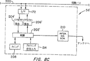
図8Cは、図6Bの同期信号バス配置と共に用いるようにされた読取り装置の簡素化された構成図を示す。
図9は、図7の読取り装置の作動を例示するフローチャートを例示する。
図10Aは、図8Aのマスタ読取り装置の作動を例示するフローチャートを例示する。
図10Bは、図8Bの従読取り装置の作動を例示するフローチャートを例示する。
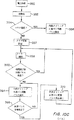
図10Cは、図8Cの読取り装置の作動を例示するフローチャートを例示する。
望ましい実施形態の説明
図1と共に論じた読取り装置56の別の面につき図3及び4を参照して以下に述べる。
まず図3を参照すると、読取り装置56の主構成要素は、コントローラボード142、無線周波数モジュール144、送信・受信多重ボード146、L拡張ボード148及びダイナミック自動同調モジュール150である。
コントローラボード142は、読取り装置56と接続される局地制御モジュール60(図1)とデータを交換しかつ他の出入口装置58(図1)に対する指令信号提供、データ交換を行うこともできる。
読取り装置コントローラボード142は、出入口アンテナ52からの問合せ信号の送信又は出入口アンテナ52を通したトランスポンダ信号の受信を制御するために、RFモジュール144及び送信・受信多重ボード146をも制御する。RF(無線周波数)モジュール144と関連するL拡張ボード148は、読取り装置56とアンテナ52を接続するケーブルの長さの変化に対し読取り装置56を適応させるために設けられる。ダイナミック自動同調モジュール150は、出入口アンテナを適切な同調状態に保つためにRFモジュール144と関連して設けられる。
読取り装置コントローラボード142の詳細は図4に示す。コントローラボード142は制御器152を含む。同制御器は、ダラスセミコンダクタ社(Dallas Semiconductor Corp.、ダラス、テキサス)から入手可能な80C32型マイクロコントローラのような、従来の制御回路から構成することができる。各種の制御及び較正設定信号を与えるために、入力装置154が制御器152と接続される。制御器152は同様に従来の電力調節及び電磁障害抑制回路機構156とも接続される。マイクロコントローラ152及び各種の入出力・周辺装置間でデータ及び制御信号を送るためにインタフェースデコーダ158が設けられる。同装置には、ウエイガンド(Weigand)符号化装置160、RS232インタフェース162、RS485インタフェース164、リレードライバ・インタフェース166、LEDドライバ・インタフェース168及びピエゾドライバ・インタフェース170が含まれる。これらの装置を通して与えられるか若しくは受信される信号の特性は、既に参照した出願第08/437,313号に詳述されている。
RS422インタフェース172も同様に周辺デコーダ158を介して制御器152と接続される。RS422インタフェース172は、以下に述べる技術により、資産追跡制御システム50内の読取り装置56及び他の読取り装置の作動を同期させるのに用いられる同期信号を受信、送信するために設けられる。
資産追跡制御システムに含まれる読取り装置のすべて又は一部のものを相互接続する連鎖配置は図5に示す通りである。もし全数未満の読取り装置が共に相互接続されるなら、少なくとも隣接読取り装置の各グループが相互接続されることを理解すべきである。図5に示す通り、読取り装置56−1は一連の読取り装置の先頭にあり、他の読取り装置56は読取り装置56−1の下流に設けられる。信号路接続201は、読取り装置56−1から連鎖内の次の読取り装置まで設けられかつ読取り装置56−1の下流の各読取り装置から連鎖内の後続の読取り装置まで設けられる。信号路接続201は、例えば、18ゲージのねじれ対ワイヤの形で設けられる。各読取り装置の場合、同期信号接続はそれぞれの読取り装置のRS422インタフェース及び関連した出入口を通してなされることを理解されたい。
図5は各読取り装置56によって制御されるそれぞれのアンテナ52も示す。共に連鎖されたアンテナ52の数は、もちろん図5に明示的に示す4つの読取り装置を越える。
図7は、図5の連鎖配置で用いるようにされた読取り装置56の実施形態を図式的に簡素化した形で例示する。
図7に示す通り読取り装置56は、制御機能202、同期パルス検出機能204、同期パルス発生機能206、タイミング機能208及び問合せ信号発生機能210を含む。機能202、204、206及び208は、少なくとも部分的に、制御器152(図4)によって構成し得る。
制御機能202に対するプログラミング信号は、既に述べた入力装置154(同様に図7に示す)によって与えられる。
電源装置212(少なくとも部分的に電力調節及びEMI回路156によって構成し得る)は、読取り装置56を構成する構成要素に対する電源として読取り装置56内に設けられる。電力感知機能214は、電源装置212の故障を検出する目的で電源装置212と結合される。電力感知機能214は、部分的に制御器152によって構成し得る。
読取り装置56は、同期信号を受信する入力ポート216及び読取り装置56で発生される同期信号を送信する出力ポート218をも有する。リレイ回路220は、入力ポート216及び出力ポート218間に接続される。リレイ回路220は通常図7の位置に保持され、入力ポート216で受信される同期信号が提供されて同期パルス検出機能204によって検出されるようにされる。しかし、電力感知機能214を通して電力停止が検出されるなら、リレイ回路220の位置は切り替えられ、入力ポート216が直接出力ポート218と接続される。このように読取り装置56に対する給電停止では、図5に示す同期信号回路網の『連鎖は決して遮断』されない。ポート216、218、リレイ回路220及びパルス検出及び発生機能の一部は、図4に示すRS422インタフェース172によって構成し得る。
図7に示す読取り装置56の作動につき図9のフローチャートを参照して以下に述べる。
読取り装置に電力が供給された後(段階250)、初期化ルーチンが実施される(段階252)。
段階252に次いで段階258が行われる。段階258において所定の休止間隔が開始される。例えば、休止間隔は図2に示す問合せ信号周期の持続時間の2倍程度であってもよい(すなわち、時間T1から時間T2までの間隔の2倍)。段階258に続く段階260において、休止期間の満了に先立って同期信号が読取り装置の入力ポート216で受信されるかどうかが決定される。
問題の読取り装置が連鎖の先頭ではなくて当該読取り装置から上流の他の読取り装置がマスタ装置として適切に機能していると初めに仮定し得る。この場合、同期信号は休止に先立って受信され、問題の読取り装置がスレーブとして機能しかつ段階262が段階260に続くようになる。段階262において当該読取り装置は、入力ポート216で受信する同期信号に応答して同期信号を発生させ、当該読取り装置によって発生される同期信号を出力信号218から送信する。同様に当該読取り装置によって受信される同期信号に応答しかつ出力信号218を通して送信されるべき同期信号の発生と同期して、同読取り装置は問合せ信号を発生させる。従って、当該読取り装置がスレーブとして機能している場合、同読取り装置によって問合せ信号が発生されるタイミングは、同期信号が入力ポート216で受信されるタイミングによって制御されることが理解されるであろう。
段階262に次いで、図9の手順は輪をなして段階258に戻り、そこで休止期間が再開始される。同期信号が所望の一定間隔で受信されると仮定すると、図9の手順は、単純に段階258、260及び262を通して反復的に輪を形成し、受信される同期信号と同期して一定間隔で連鎖を下って再送信していくために問合せ信号及び同期信号を発生させる。
読取り装置56は、受信される同期信号の検出並びに受信される同期信号に応答して行われる同期信号の発生及び再送信が極めて速やかに行われかつ連鎖を下って行われる信号伝播遅延が所望の問合せ信号周期(図2)の持続時間と比べて最小になるように配置される。
次に、先の仮定とは反対に、問題の読取り装置が連鎖の先頭に位置するか若しくは何等かの理由で(マスタ装置として作動していた上流の読取り装置の停止のような)同期信号が所定の停止期間内に受信されないと仮定される。いずれの場合においても段階264が段階260に続き、問題の読取り装置がマスタ装置として作動するようにされる。特に、段階264において、読取り装置は同期信号を発生させ、また読取り装置の内部タイミング機能に基づきかつ図2に示すタイミング周期に従って同期信号と同期して問合せ信号をも発生させる。しかし、読取り装置はそれに加えて入力ポート216(段階266)で受信する同期信号を『傾聴』し続ける。入力ポート216で同期信号が受信されない限り、独自のタイミングに基づいて同期信号及び問合せ信号を発生し続け、それによって全連鎖に対してマスタ装置として機能するか若しくは読取り装置から下流の連鎖部分に対してバックアップマスタ装置として機能する。しかしもし入力ポート216で同期信号が受信されるなら、次いで段階268が段階266に続く。段階268においては、段階262と同様な方法で、読取り装置は出力ポート218を介して送信されるべき同期信号を内部的に発生させることによって受信される同期信号に応答し、また読取り装置56は同様に問合せ信号を発生させる。さらに読取り装置は、その内部タイミング(段階270)に基づいて同期信号及び問合せ信号の発生を停止し、手順が輪に沿って段階258に戻り、それによって読取り装置がスレーブとして機能する段階258、260及び262から成るループに戻される。
本発明の望ましい実施形態によると、図5に示す各読取り装置は図7に示すものと同一であり、図9のフローチャートに従って作動する。すなわち、連鎖の先頭にある読取り装置56−1は、マスタ装置として作動し、他の読取り装置はスレーブとして作動する。マスタ装置以外の各読取り装置は同期信号を受信し、受信する同期信号に応答して連鎖を下って伝播されるべき同期信号を発生させる。同様にマスタ装置以外の各読取り装置は、問合せ信号を発生させることによって受信する同期信号に応答する。このように連鎖を通して(既に述べた通り最小の遅延で)伝播する同期信号は、連鎖を構成するすべての読取り装置が同期した問合せ信号周期で作動するようにさせ、それによって各アンテナが隣接アンテナの問合せ信号周期のトランスポンダ信号受信部分と干渉することを防止する。
資産追跡制御システムに含まれるどの読取り装置も同一連鎖と接続されることが本発明の計画範囲内にある。その代わりに、互いに相互干渉するのに十分な程度近接するあらゆるアンテナ対が同一連鎖を介して接続されるように構成される場合には2以上の連鎖も可能である。
マスタ装置として作動している読取り装置が停止する場合には、連鎖内の次の装置がその入力ポートにおいて同期信号の不在を検出し、図9の段階264に従ってバックアップマスタ装置として肩代わりするであろう。もしバックアップマスタ装置として作動している読取り装置が停止するなら、連鎖内の次の読取り装置がマスタ装置の機能を代わりに引き受けるであろう。既に述べた通り、一スレーブが停止するなら、当該スレーブがその入出力ポート間を直接接続し、停止したスレーブのみが外されて連鎖の作動バランスは保たれるようにされる。図5の配置により設けられ得るバックアップ装置数は、実際問題として、共に連鎖結合されている読取り装置の数によってのみ限定されることを理解されるであろう。このように高度な冗長性が設けられ、たとえマスタ装置及び1以上のバックアップ装置が停止しても資産追跡制御システムは十分な作動を継続する。
マスタ装置の停止に際して2以上のスレーブ間ではバックアップマスタ装置として肩代わりするための争奪が起きる可能性があるが、このような争奪はマスタからすぐ下流の装置が有利になるように1又は2問合せサイクル以内に即座に解決されるであろう。争奪の解決は、マスタに最も近いスレーブから下流の装置において段階266、268、270の作動に起因するものである。
図5に示す連鎖配置は本発明の望ましい実施形態である。その理由は、同期信号の送信及び再送信に要する信号電流レベルが比較的低くかつ前節で述べたバックアップ装置の自動優先化が行えるためである。それにもかかわらず図6Aに例示する通り、共通バス構成配置でマスタ装置に対する多重バックアップを提供することも考慮されている。特に図6Aの配置は、多くの読取り装置56M(56M−1を含めて)が接続され、マスタ装置として作動し得る共通同期バス300及び読取り装置56Sのさらなるグループを含む。同読取り装置はスレーブとして機能し、マスタとして作動する読取り装置56Sの1つから同期バス300を介してスレーブに送信される同期信号に応答して問合せ信号を発生させる。
各スレーブ56Sは、同期バスに存在する同期信号を受信するように同期バス300と接続されることは理解されるであろう。さらに、同期信号を同期バスに適用し得るように読取り装置56Mは同期バス300と接続されるが、マスタ装置として作動する装置のみが同期バスに同期信号を与える。
読取り装置56Mは接続301によって連鎖配置内に接続され、読取り装置56M−1が連鎖の先頭になり、次いで2つのバックアップ装置が続くことが観察分されるであろう。1つ又は3つ以上のバックアップ装置が読取り装置56M−1と連鎖され得ることが考慮されている。また同期バス300には、図6Aに明示するように2つ以下又は4つ以上のスレーブ56Sが接続されかつ同期バス300の任意の点にスレーブが接続されることが考慮されている。マスタ及びバックアップ装置も同様に同期バス300の任意の点に接続し得るが、マスタ及びバックアップ装置が互いに近接してい場合にはマスタ及びバックアップ装置の連鎖結合がより容易に行い得る。
それぞれ8A及び8Bに示す通り、マッスタ及びバックアップ装置並びにスレーブ56Sは、図5の連鎖配置で用いられる読取り装置56Mとは幾分異なる。特に、図8Aに示す装置56Mでは、入力ポート216及び同期信号検出機能204を介して同期信号を受信するために制御機能202Mが接続される。さらに各読取り装置56Mは、読取り装置が同期信号をバス300に加え得るようにするために同期信号発生回路206を介して同期バス300と接続される制御機能202M及びRS422インタフェース172を有する。問合せ信号発生機能210及びプログラミング信号入力装置154も同様に制御機能202Mと関連し、これらの全てが図7に示す読取り装置の対応部分と同様であり得る。
先頭装置56M−1及びバックアップ装置の連鎖配置は、ポート216及び218を通して実施される。各装置56Mは、その入力ポート216を先行装置の出力ポート218と接続されかつ出力ポート218が次ぎの装置の入力ポート216と接続されるようにされるが、先頭装置56M−1の入力ポートは他のいかなるポートとも接続されず、それゆえにいかなる同期信号も受信せず、また最後(右端)の装置56の出力装置は、同期信号を送信するために他のいかなる装置56Mの入力ポートへも接続されない。図8Aには示してないが、各読取り装置56Mは、その入力及び出力ポート間を選択的に直接接続する機構(図7のスイッチ220及び電力関知機能214のような)を含み得る。
連鎖読取り装置56Mの作動は図10Aに例示されているが、読取り装置56(図7及び9)ものとの同様である。図10Aの作動手順は図9のものと類似してので詳説は要せず、図10Aの段階264及び266間に段階265を含めることに止める。段階265は、装置56Mがマスタ装置として機能している時その出力ポート218を介して同期信号を第1バックアップ装置(補助装置)へ送信すると同時に同期信号を同期バス300に加えることを示す。(対照してみると、連鎖配置では先頭装置のみがその出力ポートから同期信号を送信する。)それとは異なり、図10Aの手順は図9のものと同様である。即ち、段階258−262のループはバックアップ装置としての作動を表し、段階264−266のループはマスタ装置としての作動を表す。マスタ装置として作動する時、読取り装置は内部タイミングに基づいて問合せ及び同期信号を発生させ、同期バスを介して同期信号をスレーブの全てにかつ出力ポート218を介してすぐ下流のバックアップ装置の双方に送信する。
バックアップ装置として作動する時、読取り装置はその入力ポートを介して受信する同期信号に応答してのみ問合せ及び同期信号を発生させかつ、このモードでは、読取り装置はその出力ポートを介して同期信号を再送信するのみである。即ち、バックアップ装置は、マスタ装置として作動しない限り同期バスを通して同期信号を再送信することはない。
図9の手順におけるように、読取り装置56が作動するモードは、その入力ポートにおける同期信号の有無によって決定される。もし同期信号が休止期間より短い短い一定間隔で受信されるなら、読取り装置56は補助モードに止まる。連鎖の先頭にある装置56M−1に対しては、もちろん同期信号は与えられず、装置56M−1は自動的にマスタモードに入るようにされる。他の装置は、マスタ装置が停止しない限り補助モードに止まる。図9で論じた通り、争奪は連鎖内の位置に基づいて解決される。
スレーブ56Sは、簡略化された機能的形で図8Bに例示される。各装置56Sは、インタフェース172及び同期検出機能204Sを介して同期バス300から同期信号を受信するために接続される制御機能202Sを含む。問合せ信号発生機能210は、制御機能202Sの制御下で問合せ信号を発生させる。図10Bに示す通り、従読取り装置56Sは、同期バス300に与えられる同期信号に応答してのみ問合せ信号を発生するように作動する。特に、従読取り装置は給電されかつ初期化され(図10の段階280及び282)てから同期信号(段階284)を受信するために待機する。同期信号の受信に際し従読取り装置は問合せ信号(段階2869を発生させ、その後同期信号を受信するために再び待機する。従読取り装置のすべてが同一方法で作動し、従ってすべての読取り装置56Sの作動は、マスタ装置として作動する読取り装置56の制御下で同期バスを通して同期化される。
スレーブが同期バス300を通して制御されかつマスタ装置とバックアップ装置間の優先順位が連鎖接続を通して決定されるので、図6Aの同期回路網配置はバス及び連鎖配置の混成物(ハイブリッド)と考え得る。マスタ及びバックアップ装置が読取り装置である必要はなく、即ち、問合せ信号発生及びマーカ信号読取り機能を含むことを要しないことに注目のこと。
本発明によりマスタ同期装置及び多重バックアップ装置を有する『純』バス配置を与えることも同様に考慮されている。図6に示すこのような配置は、そのすべてがマスタ装置として作動可能にバスに取付けられる複数の読取り装置56′を有する同期バス300を示す。
バス300に取付けられる読取り装置の数は、勿論、図6Bの明示する4つの装置より遥かに多い。他の装置の同期を制御するマスタ装置と呼ばれる読取り装置56′は、同期バス300に沿った任意の点に位置づけられ得る。
図8Cに例示する通り、読取り装置56′はインタフェース回路(図4に示すRS422インタフェース172によって構成される)を通してバス300と接続され、制御機能202′、同期信号検出機能204′、同期信号発生機能206′を含む。機能202′、204′、206′は、概して図7に関して述べた読取り装置56の機能202、204、206と同様である。図8Cの読取り装置56′も同様にプログラミング信号入力装置154、内部タイミング機能208、問合せ信号発生機能210を含み、これらのすべては読取り装置56の対応部分とほぼ同一である。
図10Cを参照して以下に読取り装置56′につき記載する。
給電(段階350)された後、初期化ルーチン(段階352)が行われる。その後段階354において読取り装置56′が、同期バスと接続されるすべての読取り装置のタイミングを制御するマスタ装置として作動するようにされたかどうかが決定される。この決定は、例えば、入力装置154を通して適切なプログラミング信号を受信することによるか若しくは読取り装置56′をマスタ装置として選定する信号が、先に入力装置154介して読取り装置内に入力された後読取り装置56′に記憶されたかどうかを決定することによってなし得る。
もし段階354において読取り装置がマスタ装置として選定されたことが決定されたなら、段階356に進み、そこで読取り装置56′は、読取り装置56′に含まれるタイミング機能208によって与えられるタイミングに基づいて一定間隔で同期信号を発生させる。この場合読取り装置56′は、読取り装置56′内で発生される同期信号と同期して問合せ信号発生機能を通して問合せ信号をも発生させる。特に、同期信号及び問合せ信号の双方が図2に例示するタイミング周期により発生されることが理解されるであろう。
図6Bの共通バス配置は、図5及び6Aの配置で与えられるように、連鎖の先頭に近いことに基づいてバックアップ装置間の優先順位を設定させることはない。従って潜在的補助マスタ装置間の優先順位を設定する他の方法が必要となる。図6Bのバスに基づく望ましい実施形態によると、バックアップ装置が異なったそれぞれの休止期間を持つようにさせることによってバックアップ装置間の優先順位が設定される。特に、図10Cの手順では、特定の読取り装置がマスタ装置として作動するように選定されないなら、段階357が段階354に続く。さらなる初期化段階と考えられる段階357において、他のいかなる読取り装置の休止期間とも異なる休止期間(より長いか又はより短い)を持つように、読取り装置はその休止期間を設定する。これは、例えば、各バックアップ装置(2、3、4等)に対する独特なアドレスを与え、次いでそのアドレスを基準として各読取り装置に対する休止期間を計算することによって行い得る。このアドレス計画を用いて、アドレス2の読取り装置は持続時間が問合せ信号周期の2倍と等しい休止期間を持つこと、アドレス3の読取り装置は持続時間が問合せ信号周期の3倍と等しい休止期間を持つこと等が可能であろう。
段階357に続く段階358において休止期間が開始される。その後読取り装置は同期バス300を介して同期信号を受信するために待機し、読取り装置の休止期間の終りまでに同期信号が検出されるなら、読取り装置は同期信号の受信に応答して問合せ信号を発生させ、次いでループルーチンにより段階358に戻る。マスタ装置が適切に作動する限り、他の各読取り装置の先決休止期間より短い一定間隔で、マスタ装置によって同期信号が同期バス300に与えられ、各読取り装置は段階358及び360で与えられる従モードでの作動を継続するであろう。その結果読取り装置のすべてが、マスタ装置によって生成される同期信号と同期して問合せ信号を発生するであろう。しかし、もしマスタ装置が停止するなら、少なくとも1つの読取り装置が休止し、この場合その読取り装置が段階360から段階364へ進むであろう。段階364で休止する当該読取り装置はマスタ装置として引継ぎ、その内部タイミングに基づいて同期信号を発生させる。これらの同期同期信号は同期バス300を通して他の読取り装置に送信され、補助マスタ装置として作動する読取り装置を含めて読取り装置のすべてが、バックアップ装置によって発生される同期信号と同期して問合せ信号周期を発生するようにされる。この間にバックアップ装置は、マスタ装置が作動状態に戻るか若しくは他の装置が補助マスタ装置として肩代わりせんとしている場合起こり得る同期パルス争奪を聴取するためにバスに波長を合わせる。もし争奪が検出されるなら、読取り装置は段階366から段階370に進み、そこで読取り装置はその内部タイミングに基づく同期信号の発生を中止し、段階358及び360のループへ戻る。読取り装置間の休止周期の差のためにいかなる争奪も速やかに解決される(即ち、数問合せ周期以内に解決される)。
図6A及び6Bの同期バス300は、適切な導線又はケーブル接続の形をとるのが望ましいが、分担された無線通信チャンネルの形で与えることもできることに注目のこと。図8Bに示すスレーブ56Sの数は、図6Bの純バス配置の形で同期バス300と接続し得ることも考慮されている。
本明細書で開示される同期技術は資産追跡制御システム読取り装置に関して記載したが、本発明は他の種類の電子装置にも適用できることも同様に考慮されている。例えば、開示された技術は、回転位相の形て同期される多数のディスク駆動機構から成るディスク駆動機構装置で用いることができる。資産追跡制御システム内の読取り装置は、システムの一部である局部制御モジュール60(図1)を通して同期し得ることも同様に考慮されている。特に局部制御モジュールは、既に開示した連鎖、バス技術により同期させることが可能であり、その後各局部制御モジュールは、局部制御モジュールを相互接続するために用いる連鎖又はバス同期回路網を通して与えられるそれぞれの読取り装置に同期信号を送る。
本発明から逸脱することなく上記実施形態の各種の改変が可能である。従って、本明細書で述べた特に望ましい実施形態は、制限ではなくて例示を意図とするものである。本発明の真の趣旨及び範囲は以下の特許請求の範囲に明記する通りである。 Field of Invention
The present invention relates to a method and apparatus for synchronizing the operating time of each of a plurality of electronic devices.
Background of the Invention
Co-pending application Ser. No. 08 / 437,313 “Zone-based asset tracking control system” (assignee and inventor is the same as the present application) is an individual or object by a transponder attached to the individual or object. An integrated system is disclosed that continues to automatically track the position of the device. The disclosure of that application is incorporated herein by reference. The asset tracking control system disclosed in the same application is considered as a kind of electronic article monitoring system and detects a multi-bit marker identification signal generated by the marker in addition to detecting the presence of the marker.
The asset tracking control system disclosed in the above-mentioned co-pending patent application will be outlined with reference to FIG. Reference numeral 50 in FIG. 1 generally indicates an asset tracking control system. The system includes a group of
Reader 56 is similarly connected to exchange data with
The
Data representing individuals or assets passing through various gateways is passed through the local control module to provide a wide range of virtually real-time database records showing the movement of individuals and assets carrying the transponders used in the system. Is mounted on the
The transponder used as the marker 54 in the preferred embodiment of the system 50 is of the type provided by Texas Instruments with a "TIRIS" automatic identification system. This type of transponder does not have a battery or any other type of internal power supply. Conversely, an interrogation signal is transmitted from the
A typical query / response cycle for a "Tiris" transponder is shown in FIG.
The horizontal axis in FIG. 2 represents the elapsed time, and the vertical axis represents the charge state of the transponder storage capacitor.
An interrogation signal / power burst is transmitted from the
A problem encountered with this type of transponder system is the need to synchronize the operation of readers that control adjacent antenna devices. In particular, if an interrogation signal transmitted from one antenna is generated simultaneously with a marker identification signal transmitted by a marker just interrogated by an adjacent antenna, the marker identification signal is interfered by a concurrent adjacent interrogation signal, i.e. Be disturbed.
According to known techniques to solve this problem, a reader or other device is called a “master” and is timed to all readers in the system or all readers in an adjacent reader group, i.e. , Send a synchronization signal. The reader confirms the synchronization signal and transmits an inquiry signal only at a timing determined by the synchronization signal transmitted by the master device. The disadvantage of this technique is that most or all of the asset control system becomes inoperable if the master device happens to stop.
Other known techniques do not use a master device that generates a synchronization signal. Instead, each reader is required to listen for potential interference signals and initiate an interrogation / response cycle only when no interference signals are detected. The disadvantage of this technique is that the timing at which each reader sends an interrogation signal is not determined and is indefinitely delayed, resulting in a reduction in the number of interrogation periods per unit time, and system performance in terms of transponder detection and tracking. It is to deteriorate.
In a system using a master device, it is conceivable to monitor the operation of the master device and provide a backup device that takes over as the master when detecting a malfunction of the master device. (This method has been used in disk drives, where it is desirable to synchronize the rotational phases of each of the multiple drives in the device.) However, even in this case, both the master and backup devices The outage will eliminate the system or most of its capabilities.
Objects and Summary of the Invention
Accordingly, it is an object of the present invention to provide a method and apparatus for synchronizing the operation of a plurality of electronic devices.
It is a further object of the present invention to provide a method and apparatus for synchronizing the start of an inquiry response period with multiple readers in an asset tracking control system.
According to one aspect of the invention, a method for synchronizing a plurality of electronic devices including a master device and a plurality of other devices is provided. The method transmits a synchronization signal from the master device to at least one of the other devices at a predetermined interval, and in each of at least two of the other devices, at least two other devices within each predetermined time period. From detecting whether a synchronization signal has been received by each and changing the operating mode of each other device if the synchronization signal has not been received by each other device within each predetermined time period. Become.
Further in accordance with this aspect of the invention, if the synchronization signal is not received by each other device within each predetermined time period, the operating mode of each other device is to receive the synchronization signal. From the first mode in which each other device transmits a synchronization signal in response to only, it is possible to switch to the second mode in which each other device transmits a synchronization signal at a predetermined interval without receiving the synchronization signal. Instead, if the synchronization signal is not transmitted to each other device within each predetermined time period, the operation mode of each other device is the first mode in which each other device does not transmit a synchronization signal. To the second mode in which each other device transmits a synchronization signal at a predetermined interval.
According to another aspect of the invention, a synchronized circuit of an electronic device is provided. The circuit comprises a plurality of electronic devices and means for interconnecting devices for transmitting synchronization signals between the devices. The plurality of devices are: a) a master device that transmits a synchronization signal to at least one of the electronic devices at a predetermined interval; and b) at least two backup devices, each backed up within a predetermined time period. A backup device for detecting whether a synchronization signal has been received by the device, and for transmitting a synchronization signal at a predetermined interval if no synchronization signal is received by each backup device within each predetermined time period.
According to the latter aspect of the invention described above, the interconnect device may include means for interconnecting the devices in a chained fashion. In response to receiving the synchronization signal from the previous device, each device other than the master device transmits the synchronization signal to the next device. Each device may include a first port (entrance / exit) for receiving a synchronization signal, a second port for transmitting the synchronization signal, and relay means for selectively short-circuiting the first and second ports.
Instead, the interconnect means includes a bus line that connects all the devices in common, and the respective predetermined time periods for each backup device differ in their respective predetermined time periods and durations for each of the other backup devices. Can be done.
According to a preferred embodiment of the device circuit, each device includes means for transmitting an electronic article monitoring inquiry signal, and each device other than the master device transmits the inquiry signal in response to receiving the synchronization signal.
According to a further aspect of the invention, a synchronized circuit of an electronic device is provided. An electronic device synchronization circuit includes: a master device including means for generating a synchronization signal at regular intervals; an output terminal for outputting the synchronization signal; a second device including an input terminal connected to the output terminal of the master device; Means for generating a synchronization signal in response to receiving the synchronization signal; an output terminal for outputting a synchronization signal generated by the generation means of the second device; and an input terminal connected to the output means of the second device. A third device including: means for generating a synchronization signal in response to receiving a synchronization signal at an input terminal of the third device; and an output terminal for outputting a synchronization signal generated by the generation means of the third device. Become. Further, the second device determines whether a synchronization signal is received at the input terminal of the second device during a predetermined time period, and if the synchronization signal is received at the input terminal of the second device during the predetermined time period. If so, it includes means for generating a synchronization signal at regular intervals. The electronic device synchronization circuit further includes a fourth device having an input terminal connected to the output terminal of the third device, and whether a synchronization signal is received at the input terminal of the third device during each predetermined time period. If it is determined that no synchronization signal is received at the input terminal of the third device during each predetermined time period, the synchronization signal may be generated at regular intervals. The second, third, and fourth devices are all identical to each other and include a means for generating a signal for interrogating the electronic article monitoring marker in response to receiving a synchronization signal at the input terminal of each device It can be. Similarly, the master device can be an electronic article monitoring and reading device. The reading device includes means for generating a signal for inquiring the electronic article monitoring marker at regular intervals in synchronization with a synchronization signal generated by the master device.
According to a further aspect of the invention, an apparatus for reading an electronic article surveillance marker is provided. The apparatus comprises: a receiving means for receiving a synchronization signal; a means for generating an inquiry signal for querying a marker in response to receiving the synchronization signal by the receiving means; and a receiving means for receiving the synchronization signal during a predetermined time period. A control means for determining whether to receive the signal, and a periodic synchronization signal is generated at regular intervals in response to the control means, and the control means determines that the synchronization signal is not received by the receiving means during a predetermined time period. In other words, the synchronization means is synchronized with a periodic synchronization signal generated at a constant interval and generates a query signal at another fixed interval.
According to yet another aspect of the invention, an apparatus for reading an electronic article surveillance marker is provided. The reader comprises receiving means for receiving a synchronization signal, means for generating an inquiry to the marker, and synchronization means for generating a synchronization signal, and the reader is selectively operated in the first and second modes. In the first mode, the inquiry means and the synchronization means respond to the reception means to generate the inquiry signal and the synchronization signal, respectively, as soon as the synchronization signal is received by the receiving device, and in the second mode, the inquiry means and the synchronization means The receiver is operated to generate an inquiry signal and a synchronization signal at regular intervals in synchronization with each other during a period when the receiver is not receiving the synchronization signal, and the reader is operated with the receiving means, the inquiry means and the synchronization means. Control means for switching the device between the first and second modes in common.
According to a further aspect of the invention, a synchronized network of electronic devices is provided. The synchronization circuit network includes a master device including a circuit mechanism for generating a synchronization signal at regular intervals, a first output terminal connected to the synchronization signal bus connection, a first output terminal for transmitting the synchronization signal on the bus connection, and a synchronization signal output unit. A synchronization signal bus connection including two output terminals, a backup device that selectively generates a synchronization signal at regular intervals, and a synchronization signal that is selectively generated by the backup device is transmitted over the bus connection. A backup device including an output terminal connected to the synchronization signal bus connection and an input terminal connected to the second output terminal of the master device for receiving a synchronization signal output from the second output terminal, and a connection to the synchronization signal bus connection Receiving a synchronization signal transmitted from the first output terminal of the master device and operating in synchronization with the synchronization signal received by the slave, ie, the slave device. Consisting of. Further, the backup device according to the latter aspect of the present invention can also include a second output terminal that outputs a synchronization signal generated by the backup device, and the circuit network is a circuit that selectively generates the synchronization signal at regular intervals. An additional device including a mechanism, an output terminal connected to the synchronization signal bus connection, and an output terminal connected to the synchronization signal bus for transmitting a synchronization signal selectively generated by the additional device on the bus connection; And an input terminal for receiving a synchronization signal generated by the backup device, which is connected to the two output terminals. Similarly, each of the slaves according to the latter aspect of the invention can be an electronic article surveillance reader that includes circuitry for generating a signal for interrogating an electronic article surveillance marker in response to receiving a synchronization signal and a master. Each of the device and the backup device can be an electronic article surveillance reader.
Further, the backup device according to the latter aspect of the invention can include a circuit mechanism for determining whether a synchronization signal is received at the input terminal of the backup device during a predetermined time period. If no synchronization signal is received at the backup device input terminal during a predetermined time period, the backup device enters an operation mode in which it generates synchronization signals at regular intervals and transmits these signals on the synchronization signal bus connection. A backup device can be arranged.
The above and other objects and features of the invention will be understood from the following detailed description of the preferred embodiments and examples and the drawings, which generally represent the same components and parts with the same reference numerals.
[Brief description of the drawings]
FIG. 1 is a system configuration diagram of an asset control and tracking system to which the present invention is applicable.
FIG. 2 is a waveform diagram illustrating an inquiry and response period used with the transponder used in the system of FIG.
FIG. 3 is a block diagram of a reader for reading the transponder signal used in the system of FIG.
FIG. 4 is a block diagram of a main control board that constitutes a part of the reading device of FIG.
FIG. 5 illustrates a series of synchronization signal networks according to the present invention that interconnect the readers used in the system of FIG.
FIG. 6A illustrates a synchronization signal bus arrangement according to another embodiment of the present invention in which a slave reader is synchronized by a master device with a series of backup devices.
FIG. 6B illustrates another embodiment of a synchronization signal bus arrangement provided to synchronize a reader according to the present invention.
FIG. 7 shows a simplified block diagram of a reader adapted for use with the chained synchronization signal network of FIG.
FIG. 8A shows a simplified block diagram of a reader adapted to be used as a master device in the hybrid bus / chained arrangement of FIG. 6A.
FIG. 8B shows a simplified block diagram of a reader adapted to be used as a slave in the hybrid bus-chained arrangement of FIG. 6A.
FIG. 8C shows a simplified block diagram of a reader adapted for use with the synchronization signal bus arrangement of FIG. 6B.
FIG. 9 illustrates a flowchart illustrating the operation of the reader of FIG.
FIG. 10A illustrates a flowchart illustrating the operation of the master reader of FIG. 8A.
FIG. 10B illustrates a flowchart illustrating the operation of the slave reader of FIG. 8B.
FIG. 10C illustrates a flowchart illustrating the operation of the reader of FIG. 8C.
Description of preferred embodiments
Other aspects of the
Referring first to FIG. 3, the main components of the
The
The
Details of the
Similarly, the
A chain arrangement interconnecting all or some of the readers included in the asset tracking control system is as shown in FIG. It should be understood that if less than a total number of readers are interconnected together, at least each group of adjacent readers is interconnected. As shown in FIG. 5, the reader 56-1 is at the beginning of a series of readers, and the
FIG. 5 also shows a
FIG. 7 illustrates, in a diagrammatically simplified form, an embodiment of a
As shown in FIG. 7, the
Programming signals for the
A power supply 212 (which may be configured at least in part by the power conditioning and EMI circuit 156) is provided within the
The
The operation of the
After power is supplied to the reader (step 250), an initialization routine is performed (step 252).
Step 252 is followed by
It can initially be assumed that the reader in question is not the head of the chain and that another reader upstream from the reader is functioning properly as a master device. In this case, the synchronization signal is received prior to the pause so that the reader in question functions as a slave and step 262 continues to step 260. In
Following
The
Next, as opposed to the previous assumption, the synchronization signal (such as the shutdown of the upstream reader that was operating as the master device) is not present because the reader in question is at the beginning of the chain or for some reason. It is assumed that it is not received within a predetermined outage period. In either case,
According to a preferred embodiment of the present invention, each reader shown in FIG. 5 is identical to that shown in FIG. 7 and operates according to the flowchart of FIG. That is, the reader 56-1 at the head of the chain operates as a master device and the other readers operate as slaves. Each reader other than the master device receives a synchronization signal and generates a synchronization signal to be propagated down the chain in response to the received synchronization signal. Similarly, each reader other than the master device responds to a received synchronization signal by generating an interrogation signal. This synchronization signal propagating through the chain (with minimal delay as already mentioned) will cause all readers that make up the chain to operate in a synchronized interrogation signal period, so that each antenna will be Interference with the transponder signal receiving part of the inquiry signal period is prevented.
It is within the planning scope of the present invention that any reader included in the asset tracking control system is connected to the same chain. Instead, two or more chains are possible if every antenna pair close enough to interfere with each other is configured to be connected through the same chain.
If the reader operating as the master device stops, the next device in the chain will detect the absence of a sync signal at its input port and will assume the backup master device in accordance with
There may be a contention between two or more slaves to take over as a backup master device when the master device is shut down, but such a contention is one or two inquiry cycles so that the device immediately downstream from the master is advantageous. Will be resolved immediately within. The resolution of the contention is due to the operation of
The chain arrangement shown in FIG. 5 is a preferred embodiment of the present invention. The reason is that the signal current level required for transmission and re-transmission of the synchronization signal is relatively low, and the automatic backup device priority described in the previous section can be performed. Nevertheless, as illustrated in FIG. 6A, it is also contemplated to provide multiple backups for the master device in a common bus configuration. In particular, the arrangement of FIG. 6A includes a further group of
It will be appreciated that each
It will be observed that
As shown in 8A and 8B, respectively, the master and backup device and
The chain arrangement of the
The operation of
When operating as a backup device, the reader generates an interrogation and synchronization signal only in response to a synchronization signal received via its input port, and in this mode, the reader receives a synchronization signal via its output port. Just retransmit. That is, the backup device does not retransmit the synchronization signal through the synchronization bus unless it operates as a master device.
As in the procedure of FIG. 9, the mode in which the
Since the slave is controlled through the
It is likewise contemplated to provide a “pure” bus arrangement with a master synchronizer and multiple backup devices according to the present invention. Such an arrangement shown in FIG. 6 shows a
The number of readers attached to
As illustrated in FIG. 8C, the reader 56 'is connected to the
The reader 56 'will be described below with reference to FIG. 10C.
After power is supplied (step 350), an initialization routine (step 352) is performed. Thereafter, in
If it is determined in
The common bus arrangement of FIG. 6B does not set priority between backup devices based on being close to the top of the chain, as given by the arrangement of FIGS. 5 and 6A. Therefore, another method of setting priorities among potential auxiliary master devices is required. According to the preferred embodiment based on the bus of FIG. 6B, priorities among backup devices are set by having the backup devices have different respective idle periods. In particular, in the procedure of FIG. 10C,
In
Note that the
Although the synchronization techniques disclosed herein have been described with respect to asset tracking control system readers, it is similarly contemplated that the present invention is applicable to other types of electronic devices. For example, the disclosed technique can be used in a disk drive mechanism apparatus that consists of multiple disk drive mechanisms that are synchronized in the form of a rotational phase. It is also contemplated that readers within the asset tracking control system can be synchronized through a local control module 60 (FIG. 1) that is part of the system. In particular, the local control modules can be synchronized by the previously disclosed chain, bus technology, after which each local control module is provided through a chain or bus synchronization network used to interconnect the local control modules. Send a synchronization signal to the reader.
Various modifications of the above embodiment are possible without departing from the invention. Accordingly, the particularly preferred embodiments described herein are intended to be illustrative rather than limiting. The true spirit and scope of the invention are as set forth in the following claims.
Claims (8)
一定間隔で同期信号を発生させる手段及び該同期信号を出力する出力端子を具備するマスタ装置と、
該マスタ装置の該出力端子と接続される入力端子を具備する第2装置であって、該入力端子において同期信号を受信することに応答して同期信号を発生させる手段と、該第2装置の発生手段によって発生した該同期信号を出力する出力端子とをさらに具備する第2装置と、
該第2装置の該出力手段と接続される入力端子を具備する第3装置であって、該第2装置の入力端子において同期信号を受信することに応答して同期信号を発生させる手段と、該第3装置の発生手段によって発生する同期信号を出力する出力端子とをさらに具備する第3装置から成り、
前記第2装置は、所定の時間期間中に該第2装置の入力端子において同期信号を受信したかどうかを判断し、かつ該所定の時間期間内に該第2装置の該入力端子において同期信号を受信しなかったと判断されたなら一定の間隔で同期信号を発生させる手段をさらに含み、前記同期信号の各々は該それぞれの同期信号を受信する装置の動作を開始するためのものであることを特徴とする同期させた電子装置の回路網。A network of synchronized electronic devices in an electronic article surveillance system,
A master device comprising means for generating a synchronization signal at regular intervals and an output terminal for outputting the synchronization signal;
A second device comprising an input terminal connected to the output terminal of the master device, the means for generating a synchronization signal in response to receiving the synchronization signal at the input terminal; A second device further comprising an output terminal for outputting the synchronization signal generated by the generating means;
A third device comprising an input terminal connected to the output means of the second device, the means generating a synchronization signal in response to receiving the synchronization signal at the input terminal of the second device; An output terminal for outputting a synchronization signal generated by the generating means of the third device, further comprising a third device,
The second device determines whether a synchronization signal has been received at the input terminal of the second device during a predetermined time period, and the synchronization signal at the input terminal of the second device within the predetermined time period. Means for generating a synchronization signal at regular intervals if it is determined that the synchronization signal has not been received, each of the synchronization signals being for initiating the operation of the device receiving the respective synchronization signal. Features a network of synchronized electronic devices.
Applications Claiming Priority (3)
| Application Number | Priority Date | Filing Date | Title |
|---|---|---|---|
| US08/502,827 US5751220A (en) | 1995-07-14 | 1995-07-14 | Synchronized network of electronic devices including back-up master units |
| US08/502,827 | 1995-07-14 | ||
| PCT/US1996/011504 WO1997004614A1 (en) | 1995-07-14 | 1996-07-10 | Synchronized electronic network including backup masters |
Publications (2)
| Publication Number | Publication Date |
|---|---|
| JPH11509394A JPH11509394A (en) | 1999-08-17 |
| JP4671451B2 true JP4671451B2 (en) | 2011-04-20 |
Family
ID=23999589
Family Applications (1)
| Application Number | Title | Priority Date | Filing Date |
|---|---|---|---|
| JP50673097A Expired - Fee Related JP4671451B2 (en) | 1995-07-14 | 1996-07-10 | Synchronous electronic network with built-in backup master |
Country Status (9)
| Country | Link |
|---|---|
| US (1) | US5751220A (en) |
| EP (1) | EP0878110B1 (en) |
| JP (1) | JP4671451B2 (en) |
| AR (1) | AR002821A1 (en) |
| AU (1) | AU705920B2 (en) |
| BR (1) | BR9609720A (en) |
| CA (1) | CA2226322C (en) |
| DE (1) | DE69635994T2 (en) |
| WO (1) | WO1997004614A1 (en) |
Families Citing this family (90)
| Publication number | Priority date | Publication date | Assignee | Title |
|---|---|---|---|---|
| US6134234A (en) * | 1996-07-19 | 2000-10-17 | Nokia Telecommunications Oy | Master-slave synchronization |
| US6094416A (en) * | 1997-05-09 | 2000-07-25 | I/O Control Corporation | Multi-tier architecture for control network |
| US6061600A (en) * | 1997-05-09 | 2000-05-09 | I/O Control Corporation | Backup control mechanism in a distributed control network |
| US6147967A (en) * | 1997-05-09 | 2000-11-14 | I/O Control Corporation | Fault isolation and recovery in a distributed control network |
| US5907486A (en) * | 1997-05-09 | 1999-05-25 | I/O Control Corporation | Wiring method and apparatus for distributed control network |
| US6128318A (en) * | 1998-01-23 | 2000-10-03 | Philips Electronics North America Corporation | Method for synchronizing a cycle master node to a cycle slave node using synchronization information from an external network or sub-network which is supplied to the cycle slave node |
| JP3609599B2 (en) * | 1998-01-30 | 2005-01-12 | 富士通株式会社 | Node proxy system, node monitoring system, method thereof, and recording medium |
| JP2001077919A (en) * | 1999-09-03 | 2001-03-23 | Fujitsu Ltd | Redundant configuration supervisory control system, supervisory controller thereof and controller to be supervised |
| US7065779B1 (en) * | 1999-10-13 | 2006-06-20 | Cisco Technology, Inc. | Technique for synchronizing multiple access controllers at the head end of an access network |
| US6732202B1 (en) | 1999-11-17 | 2004-05-04 | I/O Controls Corporation | Network node with plug-in identification module |
| US8645582B2 (en) * | 1999-11-17 | 2014-02-04 | I/O Controls Corporation | Network node with plug-in identification module |
| US6611860B1 (en) | 1999-11-17 | 2003-08-26 | I/O Controls Corporation | Control network with matrix architecture |
| US6396170B1 (en) | 2000-03-29 | 2002-05-28 | Powerware Corporation | Method and apparatus for coordinating uninterruptible power supply modules to provide scalable, redundant power |
| US6891805B2 (en) * | 2001-02-06 | 2005-05-10 | Telephonics Corporation | Communications system |
| US20020105916A1 (en) * | 2001-02-06 | 2002-08-08 | Bill Smith | Method and apparatus for allocating funtions in an electronics system |
| US6988203B2 (en) * | 2001-04-06 | 2006-01-17 | Honeywell International Inc. | System and method of extending communications with the wiegand protocol |
| US7139923B1 (en) | 2001-06-27 | 2006-11-21 | Cisco Technology, Inc. | Technique for synchronizing network devices in an access data network |
| US7349430B1 (en) | 2001-06-27 | 2008-03-25 | Cisco Technology, Inc. | Addressing scheme implemented in access networks |
| US7085287B1 (en) | 2001-06-27 | 2006-08-01 | Cisco Technology, Inc. | Map routing technique implemented in access networks |
| US7746215B1 (en) * | 2001-07-10 | 2010-06-29 | Fred Bishop | RF transactions using a wireless reader grid |
| US20030028584A1 (en) * | 2001-07-13 | 2003-02-06 | Mark Coniglio | System and method for providing network management |
| US6848933B1 (en) * | 2001-11-13 | 2005-02-01 | Rockwell Automation Technologies, Inc. | System and methodology providing coordinated and modular conveyor zone control |
| US20030117281A1 (en) * | 2001-12-21 | 2003-06-26 | Timur Sriharto | Dynamic control containment unit |
| US8339265B2 (en) | 2002-01-09 | 2012-12-25 | Sensormatic Electronics, Llc. | Method of assigning and deducing the location of articles detected by multiple RFID antennae |
| US7084769B2 (en) * | 2002-01-09 | 2006-08-01 | Vue Technology, Inc. | Intelligent station using multiple RF antennae and inventory control system and method incorporating same |
| KR100518795B1 (en) | 2003-03-13 | 2005-10-05 | 삼성전자주식회사 | Re-synchronization method for ad-hoc network environment |
| JP4080366B2 (en) * | 2003-04-01 | 2008-04-23 | シャープ株式会社 | Network terminal, network system, and network terminal control method |
| KR100552490B1 (en) * | 2003-06-13 | 2006-02-15 | 삼성전자주식회사 | Coordinator switching method in ad-hoc network environment and communication of using the same |
| US20050043859A1 (en) * | 2003-08-13 | 2005-02-24 | Chia-Ming Tsai | Modular uninterruptible power supply system and control method thereof |
| DE10393614B4 (en) * | 2003-10-06 | 2012-04-05 | Mitsubishi Denki K.K. | Slave control unit |
| US7415002B2 (en) * | 2003-10-24 | 2008-08-19 | Brocade Communications, Inc. | Circuit synchronization over asynchronous links |
| US7026935B2 (en) * | 2003-11-10 | 2006-04-11 | Impinj, Inc. | Method and apparatus to configure an RFID system to be adaptable to a plurality of environmental conditions |
| DE102004004843B4 (en) | 2004-01-30 | 2010-07-22 | Siemens Ag | Bus system for controlling a component of a printing press and corresponding method |
| US7408466B2 (en) * | 2004-04-13 | 2008-08-05 | Impinj, Inc. | Adjusting RFID waveform shape in view of detected RF energy |
| US7432814B2 (en) * | 2004-04-13 | 2008-10-07 | Impinj, Inc. | Reconstructing RFID waveform shape for reuse in individual channel |
| US7436308B2 (en) * | 2004-04-13 | 2008-10-14 | Impinj, Inc. | Adjusting RFID waveform shape in view of signal from another reader |
| US7391329B2 (en) * | 2004-04-13 | 2008-06-24 | Impinj, Inc. | Performance driven adjustment of RFID waveform shape |
| US7417548B2 (en) * | 2004-04-13 | 2008-08-26 | Impinj, Inc. | Adjusting RFID waveform shape in view of signal from an RFID tag |
| US7548153B2 (en) * | 2004-07-09 | 2009-06-16 | Tc License Ltd. | Multi-protocol or multi-command RFID system |
| JP4268983B2 (en) * | 2004-07-27 | 2009-05-27 | 富士通株式会社 | Wireless interrogator system and wireless communication method thereof |
| WO2006029288A2 (en) * | 2004-09-09 | 2006-03-16 | Inteligistics, Inc. | Modular shipping unit and system |
| JP3984643B2 (en) * | 2004-10-21 | 2007-10-03 | 株式会社メディアシーク | Synchronous communication method and synchronous communication apparatus |
| WO2006047701A2 (en) * | 2004-10-26 | 2006-05-04 | Wj Communications, Inc. | Distributed rfid interrogation system and method of operating the same |
| US7646284B2 (en) * | 2004-11-17 | 2010-01-12 | Lexmark International, Inc. | Systems and apparatus for writing data to multiple RF tags contained on print media |
| WO2006075367A1 (en) * | 2005-01-13 | 2006-07-20 | Fujitsu Limited | Information access system and method for accessing information in non-contact information storage device |
| US7978060B2 (en) * | 2005-02-14 | 2011-07-12 | Inteligistics, Inc. | Identification system |
| CA2599973A1 (en) * | 2005-03-03 | 2006-09-08 | Vue Technology, Inc. | Apparatus for and method of using an intelligent network and rfid signal router |
| US20060238303A1 (en) * | 2005-04-21 | 2006-10-26 | Sean Loving | Adaptable RFID reader |
| US20070046467A1 (en) * | 2005-08-31 | 2007-03-01 | Sayan Chakraborty | System and method for RFID reader to reader communication |
| US7659819B2 (en) * | 2005-04-21 | 2010-02-09 | Skyetek, Inc. | RFID reader operating system and associated architecture |
| US7570164B2 (en) * | 2005-12-30 | 2009-08-04 | Skyetek, Inc. | System and method for implementing virtual RFID tags |
| US20080001752A1 (en) * | 2005-04-21 | 2008-01-03 | Skyetek, Inc. | System and method for securing rfid tags |
| US7728713B2 (en) * | 2005-05-06 | 2010-06-01 | Intelleflex Corporation | Accurate persistent nodes |
| US20060279406A1 (en) * | 2005-06-07 | 2006-12-14 | Robert Stewart | Synchronization and adaptive timing method for multiple RFID reader system |
| US20060289650A1 (en) * | 2005-06-27 | 2006-12-28 | Mobile Aspects, Inc. | Networked monitoring system |
| WO2007009458A2 (en) * | 2005-07-15 | 2007-01-25 | Pinocchio Data Systems Aps | Time synchronization algorithm for measurement systems with random delays |
| US20070206786A1 (en) * | 2005-08-31 | 2007-09-06 | Skyetek, Inc. | Rfid security system |
| US20080042830A1 (en) * | 2005-12-30 | 2008-02-21 | Skyetek, Inc. | Virtual rfid-based tag sensor |
| US20080022160A1 (en) * | 2005-12-30 | 2008-01-24 | Skyetek, Inc. | Malware scanner for rfid tags |
| US20070206797A1 (en) * | 2006-03-01 | 2007-09-06 | Skyetek, Inc. | Seamless rfid tag security system |
| US8316156B2 (en) * | 2006-02-17 | 2012-11-20 | Intel-Ne, Inc. | Method and apparatus for interfacing device drivers to single multi-function adapter |
| US7830262B1 (en) | 2006-04-25 | 2010-11-09 | Impinj, Inc. | Adjusting communication parameters while inventorying RFID tags |
| US7509350B2 (en) * | 2006-06-01 | 2009-03-24 | Research In Motion Limited | Method and apparatus for synchronizing of databases |
| US7884725B2 (en) | 2006-06-21 | 2011-02-08 | Neology, Inc. | Systems and methods for stirring electromagnetic fields and interrogating stationary RFID tags |
| US7535338B2 (en) * | 2006-06-27 | 2009-05-19 | Sensormatic Electronics Corporation | Wireless synchronized operation of pulsed EAS systems |
| US7526666B1 (en) * | 2006-09-06 | 2009-04-28 | Nvidia Corporation | Derived clock synchronization for reduced skew and jitter |
| US8098135B2 (en) * | 2006-10-27 | 2012-01-17 | Symbol Technologies, Inc. | Coordination of radio frequency communications amongst radio frequency identification (RFID) readers |
| US7859411B2 (en) * | 2007-03-30 | 2010-12-28 | Skyetek, Inc. | RFID tagged item trajectory and location estimation system and method |
| US8414471B2 (en) * | 2008-10-28 | 2013-04-09 | Mobile Aspects, Inc. | Endoscope storage cabinet, tracking system, and signal emitting member |
| JP5481089B2 (en) * | 2009-04-09 | 2014-04-23 | 株式会社アイ・ライティング・システム | Remote lighting control system |
| US8531273B2 (en) * | 2009-10-12 | 2013-09-10 | Osa Acquisition, Llc | Systems and methods for controlling serially connected RFID transmitters and receivers |
| US8648699B2 (en) | 2010-07-19 | 2014-02-11 | Mobile Aspects, Inc. | Item tracking system and arrangement |
| EP3048536B1 (en) * | 2011-10-05 | 2020-02-19 | Analog Devices, Inc. | Two-wire communication system for high-speed data and power distribution |
| US10649948B2 (en) | 2011-10-05 | 2020-05-12 | Analog Devices, Inc. | Two-wire communication systems and applications |
| US10142124B2 (en) * | 2012-05-24 | 2018-11-27 | Infineon Technologies Ag | System and method to transmit data over a bus system |
| TW201405315A (en) * | 2012-07-30 | 2014-02-01 | Acer Inc | Data routing system supporting dual master apparatuses |
| US8942108B2 (en) * | 2012-12-14 | 2015-01-27 | General Electric Company | Method and system for current differential protection |
| US9396367B2 (en) | 2013-02-05 | 2016-07-19 | Amtech Systems, LLC | System and method for synchronizing RFID readers utilizing RF or modulation signals |
| US9548871B2 (en) * | 2013-03-07 | 2017-01-17 | General Electric Company | Systems and methods for master arbitration |
| US9892618B2 (en) | 2013-08-09 | 2018-02-13 | Mobile Aspects, Inc. | Signal emitting member attachment system and arrangement |
| US9348013B2 (en) | 2013-09-18 | 2016-05-24 | Mobile Aspects, Inc. | Item hanger arrangement, system, and method |
| US9224124B2 (en) | 2013-10-29 | 2015-12-29 | Mobile Aspects, Inc. | Item storage and tracking cabinet and arrangement |
| CA2968432C (en) * | 2013-11-23 | 2019-12-31 | Koenig-Pa Gmbh | Bus participant device and method for the operation of a bus participant device |
| US10034400B2 (en) | 2013-12-04 | 2018-07-24 | Mobile Aspects, Inc. | Item storage arrangement system and method |
| EP2884806B1 (en) * | 2013-12-13 | 2016-05-11 | Siemens Aktiengesellschaft | Timing control in an industrial control system |
| CN106170780B (en) * | 2014-01-10 | 2019-10-18 | 飞利浦灯具控股公司 | More host bus |
| US10121289B1 (en) | 2014-04-11 | 2018-11-06 | Amtech Systems, LLC | Vehicle-based electronic toll system with interface to vehicle display |
| CN106612253B (en) * | 2015-10-23 | 2019-10-22 | 中国科学院声学研究所 | A kind of linkage control power managing device and method |
| US11526683B2 (en) * | 2018-07-16 | 2022-12-13 | Lg Electronics Inc. | Method and device for reader to transmit signal in wireless communication system |
| US11620960B2 (en) * | 2020-10-20 | 2023-04-04 | Intermec Ip Corporation | Synchronous display blinking |
Family Cites Families (21)
| Publication number | Priority date | Publication date | Assignee | Title |
|---|---|---|---|---|
| US4521871A (en) * | 1982-04-12 | 1985-06-04 | Allen-Bradley Company | Programmable controller with back-up capability |
| US4677614A (en) * | 1983-02-15 | 1987-06-30 | Emc Controls, Inc. | Data communication system and method and communication controller and method therefor, having a data/clock synchronizer and method |
| US4596012A (en) * | 1983-05-25 | 1986-06-17 | Reed Lockwood W | Master controller succession system for bus control access for data-communications local area networks |
| JPS60111551A (en) * | 1983-11-21 | 1985-06-18 | Fujitsu Ltd | Terminal address setting system |
| GB8408538D0 (en) * | 1984-04-03 | 1984-05-16 | Senelco Ltd | Transmitter-responder systems |
| US4709347A (en) * | 1984-12-17 | 1987-11-24 | Honeywell Inc. | Method and apparatus for synchronizing the timing subsystems of the physical modules of a local area network |
| JPH07104984B2 (en) * | 1985-02-28 | 1995-11-13 | オムロン株式会社 | Electronic cash register system |
| JPS61283249A (en) * | 1985-06-10 | 1986-12-13 | Canon Inc | Network control system |
| JPS6282744A (en) * | 1985-10-07 | 1987-04-16 | Nec Corp | Data transmission system |
| DE3751571T2 (en) * | 1986-05-20 | 1996-04-11 | Mitsubishi Electric Corp | Method for synchronizing real-time clocks in a data transmission system. |
| US5166678A (en) * | 1987-08-11 | 1992-11-24 | Rosemount Inc. | Dual master implied token communication system |
| JP2579963B2 (en) * | 1987-10-26 | 1997-02-12 | シャープ株式会社 | Communication method |
| JPH01256843A (en) * | 1988-03-25 | 1989-10-13 | Ncr Corp | Link control system |
| JPH077964B2 (en) * | 1989-05-19 | 1995-01-30 | 三菱電機株式会社 | Current loop transmission system |
| JP3100716B2 (en) * | 1991-01-04 | 2000-10-23 | シーエスアイアール | Identification device |
| US5231273A (en) * | 1991-04-09 | 1993-07-27 | Comtec Industries | Inventory management system |
| EP0589499B1 (en) * | 1992-08-12 | 1999-04-07 | Koninklijke Philips Electronics N.V. | A multistation communication bus system, and a master station and a slave station for use in such system |
| KR100309082B1 (en) * | 1992-08-12 | 2001-12-15 | 요트.게.아. 롤페즈 | Multistation communication bus system, main station and slave station |
| JP2757700B2 (en) * | 1992-08-20 | 1998-05-25 | 富士通株式会社 | Condition monitoring system |
| US5477215A (en) * | 1993-08-02 | 1995-12-19 | At&T Corp. | Arrangement for simultaneously interrogating a plurality of portable radio frequency communication devices |
| JPH0779186A (en) * | 1993-09-08 | 1995-03-20 | Fuji Electric Co Ltd | Polling method accompanied with relay |
-
1995
- 1995-07-14 US US08/502,827 patent/US5751220A/en not_active Expired - Lifetime
-
1996
- 1996-07-10 CA CA002226322A patent/CA2226322C/en not_active Expired - Fee Related
- 1996-07-10 DE DE69635994T patent/DE69635994T2/en not_active Expired - Lifetime
- 1996-07-10 JP JP50673097A patent/JP4671451B2/en not_active Expired - Fee Related
- 1996-07-10 BR BR9609720A patent/BR9609720A/en not_active IP Right Cessation
- 1996-07-10 WO PCT/US1996/011504 patent/WO1997004614A1/en active IP Right Grant
- 1996-07-10 AU AU64878/96A patent/AU705920B2/en not_active Ceased
- 1996-07-10 EP EP96924415A patent/EP0878110B1/en not_active Expired - Lifetime
- 1996-07-12 AR ARP960103555A patent/AR002821A1/en unknown
Also Published As
| Publication number | Publication date |
|---|---|
| US5751220A (en) | 1998-05-12 |
| EP0878110A1 (en) | 1998-11-18 |
| WO1997004614A1 (en) | 1997-02-06 |
| DE69635994D1 (en) | 2006-05-18 |
| DE69635994T2 (en) | 2007-04-12 |
| CA2226322A1 (en) | 1997-02-06 |
| EP0878110B1 (en) | 2006-03-29 |
| EP0878110A4 (en) | 1999-05-19 |
| BR9609720A (en) | 1999-07-06 |
| CA2226322C (en) | 2007-02-27 |
| JPH11509394A (en) | 1999-08-17 |
| AR002821A1 (en) | 1998-04-29 |
| AU705920B2 (en) | 1999-06-03 |
| AU6487896A (en) | 1997-02-18 |
Similar Documents
| Publication | Publication Date | Title |
|---|---|---|
| JP4671451B2 (en) | Synchronous electronic network with built-in backup master | |
| US8714449B2 (en) | Method and device for arming and disarming status in a facility monitoring system | |
| US6400725B1 (en) | Fairness scheme for a serial interface | |
| CN102045227A (en) | Communication centralized control system and communication centralized control method | |
| US6598107B1 (en) | Method for communicating data on a serial bus | |
| US20020166014A1 (en) | Data bus for several users | |
| US6934775B2 (en) | Operating method for a data bus for several users with flexible timed access | |
| US5751770A (en) | Data transmission system | |
| JPS6156906B2 (en) | ||
| JP3393059B2 (en) | Method for unidirectional communication from multiple transmitters to a single receiver | |
| JPH066256A (en) | Transmission and reception system | |
| JP3891787B2 (en) | Multi-axis servo system | |
| JP3153014B2 (en) | Transmission / reception method of wireless alarm system | |
| JPH10224874A (en) | Remote control system | |
| JPH11261607A (en) | Phase synchronization system between devices and its method | |
| JPS6336587B2 (en) | ||
| JPH0621999A (en) | Serial communication equipment | |
| JPH0233418Y2 (en) | ||
| JPH0798750A (en) | Identification system and data carrier | |
| JPH10112706A (en) | Synchronization communication circuit | |
| JPH0479433A (en) | Distributed network control system for space communication | |
| JP2863455B2 (en) | Disaster prevention monitoring device | |
| JPS601953A (en) | Polling system remote supervising and controlling equipment | |
| JPH10154280A (en) | Theft monitoring device | |
| JPH08163182A (en) | System and device for serial communication |
Legal Events
| Date | Code | Title | Description |
|---|---|---|---|
| A131 | Notification of reasons for refusal |
Free format text: JAPANESE INTERMEDIATE CODE: A131 Effective date: 20070206 |
|
| A521 | Written amendment |
Free format text: JAPANESE INTERMEDIATE CODE: A523 Effective date: 20070427 |
|
| A131 | Notification of reasons for refusal |
Free format text: JAPANESE INTERMEDIATE CODE: A131 Effective date: 20070911 |
|
| A601 | Written request for extension of time |
Free format text: JAPANESE INTERMEDIATE CODE: A601 Effective date: 20071130 |
|
| A602 | Written permission of extension of time |
Free format text: JAPANESE INTERMEDIATE CODE: A602 Effective date: 20080121 |
|
| A521 | Written amendment |
Free format text: JAPANESE INTERMEDIATE CODE: A523 Effective date: 20080311 |
|
| A131 | Notification of reasons for refusal |
Free format text: JAPANESE INTERMEDIATE CODE: A131 Effective date: 20080729 |
|
| A521 | Written amendment |
Free format text: JAPANESE INTERMEDIATE CODE: A523 Effective date: 20081029 |
|
| A131 | Notification of reasons for refusal |
Free format text: JAPANESE INTERMEDIATE CODE: A131 Effective date: 20090616 |
|
| A02 | Decision of refusal |
Free format text: JAPANESE INTERMEDIATE CODE: A02 Effective date: 20091117 |
|
| A521 | Written amendment |
Free format text: JAPANESE INTERMEDIATE CODE: A523 Effective date: 20100318 |
|
| A911 | Transfer of reconsideration by examiner before appeal (zenchi) |
Free format text: JAPANESE INTERMEDIATE CODE: A911 Effective date: 20100422 |
|
| A912 | Removal of reconsideration by examiner before appeal (zenchi) |
Free format text: JAPANESE INTERMEDIATE CODE: A912 Effective date: 20100729 |
|
| A521 | Written amendment |
Free format text: JAPANESE INTERMEDIATE CODE: A523 Effective date: 20101129 |
|
| A01 | Written decision to grant a patent or to grant a registration (utility model) |
Free format text: JAPANESE INTERMEDIATE CODE: A01 |
|
| A61 | First payment of annual fees (during grant procedure) |
Free format text: JAPANESE INTERMEDIATE CODE: A61 Effective date: 20110118 |
|
| R150 | Certificate of patent or registration of utility model |
Free format text: JAPANESE INTERMEDIATE CODE: R150 |
|
| FPAY | Renewal fee payment (event date is renewal date of database) |
Free format text: PAYMENT UNTIL: 20140128 Year of fee payment: 3 |
|
| LAPS | Cancellation because of no payment of annual fees | ||
| S111 | Request for change of ownership or part of ownership |
Free format text: JAPANESE INTERMEDIATE CODE: R313111 |
|
| R350 | Written notification of registration of transfer |
Free format text: JAPANESE INTERMEDIATE CODE: R350 |
|
| S111 | Request for change of ownership or part of ownership |
Free format text: JAPANESE INTERMEDIATE CODE: R313113 Free format text: JAPANESE INTERMEDIATE CODE: R313111 |
|
| R360 | Written notification for declining of transfer of rights |
Free format text: JAPANESE INTERMEDIATE CODE: R360 |
|
| R360 | Written notification for declining of transfer of rights |
Free format text: JAPANESE INTERMEDIATE CODE: R360 |
|
| R371 | Transfer withdrawn |
Free format text: JAPANESE INTERMEDIATE CODE: R371 |