JP4670103B2 - Silencer structure - Google Patents
Silencer structure Download PDFInfo
- Publication number
- JP4670103B2 JP4670103B2 JP2007226815A JP2007226815A JP4670103B2 JP 4670103 B2 JP4670103 B2 JP 4670103B2 JP 2007226815 A JP2007226815 A JP 2007226815A JP 2007226815 A JP2007226815 A JP 2007226815A JP 4670103 B2 JP4670103 B2 JP 4670103B2
- Authority
- JP
- Japan
- Prior art keywords
- outer cylinder
- separator
- cylinder
- diameter
- welded
- Prior art date
- Legal status (The legal status is an assumption and is not a legal conclusion. Google has not performed a legal analysis and makes no representation as to the accuracy of the status listed.)
- Expired - Fee Related
Links
Images


Classifications
-
- F—MECHANICAL ENGINEERING; LIGHTING; HEATING; WEAPONS; BLASTING
- F01—MACHINES OR ENGINES IN GENERAL; ENGINE PLANTS IN GENERAL; STEAM ENGINES
- F01N—GAS-FLOW SILENCERS OR EXHAUST APPARATUS FOR MACHINES OR ENGINES IN GENERAL; GAS-FLOW SILENCERS OR EXHAUST APPARATUS FOR INTERNAL COMBUSTION ENGINES
- F01N1/00—Silencing apparatus characterised by method of silencing
- F01N1/08—Silencing apparatus characterised by method of silencing by reducing exhaust energy by throttling or whirling
- F01N1/084—Silencing apparatus characterised by method of silencing by reducing exhaust energy by throttling or whirling the gases flowing through the silencer two or more times longitudinally in opposite directions, e.g. using parallel or concentric tubes
-
- F—MECHANICAL ENGINEERING; LIGHTING; HEATING; WEAPONS; BLASTING
- F01—MACHINES OR ENGINES IN GENERAL; ENGINE PLANTS IN GENERAL; STEAM ENGINES
- F01N—GAS-FLOW SILENCERS OR EXHAUST APPARATUS FOR MACHINES OR ENGINES IN GENERAL; GAS-FLOW SILENCERS OR EXHAUST APPARATUS FOR INTERNAL COMBUSTION ENGINES
- F01N1/00—Silencing apparatus characterised by method of silencing
- F01N1/24—Silencing apparatus characterised by method of silencing by using sound-absorbing materials
-
- F—MECHANICAL ENGINEERING; LIGHTING; HEATING; WEAPONS; BLASTING
- F01—MACHINES OR ENGINES IN GENERAL; ENGINE PLANTS IN GENERAL; STEAM ENGINES
- F01N—GAS-FLOW SILENCERS OR EXHAUST APPARATUS FOR MACHINES OR ENGINES IN GENERAL; GAS-FLOW SILENCERS OR EXHAUST APPARATUS FOR INTERNAL COMBUSTION ENGINES
- F01N13/00—Exhaust or silencing apparatus characterised by constructional features ; Exhaust or silencing apparatus, or parts thereof, having pertinent characteristics not provided for in, or of interest apart from, groups F01N1/00 - F01N5/00, F01N9/00, F01N11/00
- F01N13/18—Construction facilitating manufacture, assembly, or disassembly
- F01N13/1872—Construction facilitating manufacture, assembly, or disassembly the assembly using stamp-formed parts or otherwise deformed sheet-metal
-
- Y—GENERAL TAGGING OF NEW TECHNOLOGICAL DEVELOPMENTS; GENERAL TAGGING OF CROSS-SECTIONAL TECHNOLOGIES SPANNING OVER SEVERAL SECTIONS OF THE IPC; TECHNICAL SUBJECTS COVERED BY FORMER USPC CROSS-REFERENCE ART COLLECTIONS [XRACs] AND DIGESTS
- Y10—TECHNICAL SUBJECTS COVERED BY FORMER USPC
- Y10T—TECHNICAL SUBJECTS COVERED BY FORMER US CLASSIFICATION
- Y10T29/00—Metal working
- Y10T29/49—Method of mechanical manufacture
- Y10T29/49398—Muffler, manifold or exhaust pipe making
Landscapes
- Engineering & Computer Science (AREA)
- Chemical & Material Sciences (AREA)
- Combustion & Propulsion (AREA)
- Mechanical Engineering (AREA)
- General Engineering & Computer Science (AREA)
- Exhaust Silencers (AREA)
Description
本発明は、内筒及びセパレータを小組みした状態で、この小組体を外側から板材で巻き締めし、合わせ面を溶接して外筒を形成した多室型の消音器構造に関する。 The present invention relates to a multi-chamber silencer structure in which an inner cylinder and a separator are assembled in a small assembly, the small assembly is wound with a plate from the outside, and a mating surface is welded to form an outer cylinder.
従来、車両の多室型のマフラーにおいては、マフラーの外筒の内側で内筒及び排気管等と接続されているセパレータが、外筒と内筒の伸び量の違いを吸収するため、外筒と溶接されずに外筒の内部で外筒の軸方向に移動可能に支持されるものがある(例えば、特許文献1参照)。この構成では、外筒は、例えば、板材を筒状に曲げ、板材の両側の合わせ面を予め溶接して形成され、内筒とセパレータとを組付けて構成された小組体を、外筒の内側に挿入してマフラーを製作していた。この場合、小組体を、外筒の内側に挿入する段階で、外筒の内側にある溶接による残留物を取り除く作業が困難であった。
また、従来、車両の多室型のマフラーにおいては、セパレータとパイプを小組みした状態で、この小組体を外側から巻き締めし、合わせ面を溶接して外筒を形成したものがあった(例えば、特許文献2参照)。
Conventionally, in a multi-chamber muffler of a vehicle, there is one in which an outer cylinder is formed by winding the small assembly from the outside in a state where the separator and the pipe are assembled, and welding the mating surfaces (see FIG. For example, see Patent Document 2).
しかしながら、消音器構造が、例えば、内筒と外筒とを備え、内筒には外筒の内径と略等しい外径を有したセパレータが設けられ、外筒は内筒及びセパレータを小組みした状態で、この小組体を外側から板材で巻き締めして、合わせ面を溶接して形成する場合、この溶接により外筒とセパレータの外周部とが接合され、熱膨張等があった場合にセパレータが外筒の内部で移動できなかった。 However, the silencer structure includes, for example, an inner cylinder and an outer cylinder, and the inner cylinder is provided with a separator having an outer diameter substantially equal to the inner diameter of the outer cylinder, and the outer cylinder is a small assembly of the inner cylinder and the separator. In this state, when this small assembly is wound with a plate material from the outside and the mating surfaces are welded, the outer cylinder and the outer periphery of the separator are joined by this welding, and there is thermal expansion or the like. Could not move inside the outer cylinder.
そこで、本発明の目的は、上述した従来の技術が有する課題を解消し、巻き締めした外筒の合わせ面溶接時に外筒の内部で小組体が外筒に接合されない消音器構造を提供することにある。 Accordingly, an object of the present invention is to provide a silencer structure that eliminates the above-described problems of the prior art and prevents the small assembly from being joined to the outer cylinder inside the outer cylinder when the outer surface of the wound outer cylinder is welded together. It is in.
上述課題を解決するため、本発明は、内筒及びセパレータを小組みし、この小組体を外筒で支持した消音器構造において、前記外筒は、前記小組体を外側から板材で巻き締めして、合わせ面を溶接して形成され、前記小組体は前記外筒の溶接部にかかる部分に凹部を備えたことを特徴とする。
この発明によれば、外筒は、内筒及びセパレータの小組体を外側から板材で巻き締めして、合わせ面を溶接して形成され、この小組体は外筒の溶接部にかかる部分に凹部を備えるので、外筒の合わせ面溶接時に、外筒の溶接部が、小組体に設けられた凹部によってかわされて、外筒の内部で小組体が外筒に接合されることを防止できる。
また、小組体を外側から板材で巻き締めして、合わせ面を溶接して外筒が形成されるので、小組体を外筒の内側に挿入する工程を省くことができ、小組体の挿入のために行われていた外筒の内側の溶接痕を取り除く作業が必要ないという利点がある。
In order to solve the above problems, the present invention provides a silencer structure in which an inner cylinder and a separator are assembled in a small assembly, and the small assembly is supported by an outer cylinder. The outer cylinder is formed by winding the small assembly from the outside with a plate material. The mating surfaces are welded to each other, and the small assembly is provided with a recess in a portion of the outer cylinder that is in contact with the welded portion.
According to this invention, the outer cylinder is formed by winding the small assembly of the inner cylinder and the separator with the plate material from the outside and welding the mating surfaces, and the small assembly is recessed in the portion of the outer cylinder that covers the welded portion. Therefore, it is possible to prevent the welded portion of the outer cylinder from being displaced by the concave portion provided in the small assembly during the mating surface welding of the outer cylinder, and joining the small assembly to the outer cylinder inside the outer cylinder.
In addition, the outer assembly is formed by winding the small assembly with a plate material from the outside and welding the mating surfaces, so the step of inserting the small assembly into the outer cylinder can be omitted, and the insertion of the small assembly can be omitted. For this reason, there is an advantage that it is not necessary to remove the welding marks inside the outer cylinder.
上記構成において、前記セパレータは、前記外筒の内径と略等しい外径を有し、このセパレータの外周部に前記凹部を設けることが好ましい。この構成によれば、外筒の合わせ面溶接時に、外筒の溶接部が、外筒の内径と略等しい外径を有したセパレータに形成された凹部によってかわされて、外筒の内部でセパレータが外筒に接合されることを防止できる。 The said structure WHEREIN: It is preferable that the said separator has an outer diameter substantially equal to the internal diameter of the said outer cylinder, and provides the said recessed part in the outer peripheral part of this separator. According to this configuration, during the mating surface welding of the outer cylinder, the welded portion of the outer cylinder is displaced by the recess formed in the separator having an outer diameter substantially equal to the inner diameter of the outer cylinder, and the separator is formed inside the outer cylinder. Can be prevented from being joined to the outer cylinder.
上記構成において、前記内筒は、その一部が拡径して前記外筒の内径と略等しい外径を有する拡径部を有し、前記拡径部の外周部に前記凹部を設けることが好ましい。この構成によれば、外筒の合わせ面溶接時に、外筒の溶接部が、外筒の内径と略等しい外径を有した内筒の拡径部に形成された凹部によってかわされて、外筒の内部で内筒が外筒に接合されることを防止できる。 In the above-described configuration, the inner cylinder has a diameter-expanded portion that has a diameter that is partially enlarged and has an outer diameter that is substantially equal to the inner diameter of the outer cylinder, and the concave portion is provided on an outer peripheral portion of the diameter-expanded portion. preferable. According to this configuration, during the mating surface welding of the outer cylinder, the welded portion of the outer cylinder is replaced by the recess formed in the enlarged diameter portion of the inner cylinder having an outer diameter substantially equal to the inner diameter of the outer cylinder, It is possible to prevent the inner cylinder from being joined to the outer cylinder inside the cylinder.
上記構成において、前記外筒と前記内筒との間に吸音材を設け、前記凹部と前記外筒との間を埋める栓部材を設けることが好ましい。この構成によれば、栓部材によって小組体の凹部と外筒との間が埋められ、外筒と内筒との間に設けられた吸音材が外部に飛散することを防止できる。 The said structure WHEREIN: It is preferable to provide the sound absorbing material between the said outer cylinder and the said inner cylinder, and to provide the plug member which fills between the said recessed part and the said outer cylinder. According to this configuration, the gap between the concave portion of the small assembly and the outer cylinder is filled with the plug member, and the sound absorbing material provided between the outer cylinder and the inner cylinder can be prevented from scattering to the outside.
本発明では、外筒は、内筒及びセパレータの小組体を外側から板材で巻き締めして、合わせ面を溶接して形成され、この小組体は外筒の溶接部にかかる部分に凹部を備えるため、外筒の合わせ面溶接時に外筒の内部で小組体が外筒に接合されることを防止できる。
また、セパレータは、外筒の内径と略等しい外径を有し、このセパレータの外周部に凹部を設けたため、外筒の合わせ面溶接時に外筒の内部でセパレータが外筒に接合されることを防止できる。
また、内筒は、その一部が拡径して外筒の内径と略等しい外径を有する拡径部を有し、拡径部の外周部に凹部を設けたため、外筒の合わせ面溶接時に外筒の内部で内筒が外筒に接合されることを防止できる。
また、外筒と内筒との間に吸音材を設け、凹部と外筒との間を埋める栓部材を設けているため、栓部材によって吸音材が外部に飛散することを防止できる。
In the present invention, the outer cylinder is formed by winding a small assembly of the inner cylinder and the separator with a plate material from the outside and welding the mating surfaces, and this small assembly is provided with a recess in a portion of the outer cylinder corresponding to the welded portion. For this reason, it is possible to prevent the small assembly from being joined to the outer cylinder inside the outer cylinder during the welding of the mating surfaces of the outer cylinder.
In addition, since the separator has an outer diameter substantially equal to the inner diameter of the outer cylinder, and a recess is provided in the outer peripheral portion of the separator, the separator is joined to the outer cylinder inside the outer cylinder when the outer cylinder is welded to the mating surface. Can be prevented.
In addition, the inner cylinder has a diameter-enlarged portion that is partially enlarged and has an outer diameter that is substantially equal to the inner diameter of the outer cylinder. Sometimes it is possible to prevent the inner cylinder from being joined to the outer cylinder inside the outer cylinder.
In addition, since the sound absorbing material is provided between the outer cylinder and the inner cylinder and the plug member that fills the space between the recess and the outer cylinder is provided, the sound absorbing material can be prevented from being scattered to the outside by the plug member.
以下、本発明の一実施形態を添付した図面を参照して説明する。以下の説明中、前後左右及び上下といった方向の記載は車体に対してのものとする。また、図中矢印FRは車体前方を、矢印Rは車体右方を、矢印UPは車体上方をそれぞれ示している。
[第1の実施の形態]
図1は、本発明を適用した第1の実施の形態に係る鞍乗り型車両の側面図であり、図2はその上面図である。
この鞍乗り型車両1は、ATV(不整地走行車両)に分類される4輪車両であり、小型軽量に構成された車体の前後に比較的大径の左右の前輪2及び後輪3を備え、最低地上高を十分に確保して不整地の走破性を高めている。
Hereinafter, an embodiment of the present invention will be described with reference to the accompanying drawings. In the following description, descriptions of directions such as front and rear, right and left, and up and down are for the vehicle body. In the drawing, an arrow FR indicates the front of the vehicle body, an arrow R indicates the right side of the vehicle body, and an arrow UP indicates the upper side of the vehicle body.
[First Embodiment]
FIG. 1 is a side view of a saddle-ride type vehicle according to a first embodiment to which the present invention is applied, and FIG. 2 is a top view thereof.
The saddle-ride type vehicle 1 is a four-wheel vehicle classified as an ATV (roughly terrain vehicle), and includes front and
鞍乗り型車両1は、図1に示すように、車体フレーム4を有し、この車体フレーム4の前部にフロントサスペンション50を介して左右の前輪2が懸架され、車体フレーム4の後部にリヤサスペンション59を介して左右の後輪3が懸架される。
車体フレーム4の略中央部には、複数のエンジンマウント70を介してエンジン(水冷エンジン)5が支持される。このエンジン5のシリンダ部7の後部には、スロットルボディ20が接続され、このスロットルボディ20の後部にはコネクティングチューブ21を介してエアクリーナケース22が接続され、これらがエンジン5の吸気系を構成している。また、エンジン5のシリンダ部7の前方には、排気管23が接続され、この排気管23は、図2に示すように、シリンダ部7の前方に延びた後に車体右方に屈曲して後方に向けて折り返し、シリンダ部7の右側方を後方に延びた後、車体後部に配置されたマフラー24に接続され、これらがエンジン5の排気系を構成している。
なお、図2において、符号11はシフトペダルであり、符号12はブレーキペダルであり、符号13、13は足置きステップであり、14はバッテリである。
As shown in FIG. 1, the saddle-ride type vehicle 1 has a
An engine (water-cooled engine) 5 is supported at a substantially central portion of the
In FIG. 2,
図1に示すように、エンジン5の前方には、エンジン冷却用のラジエータ25が配設されている。このラジエータ25は、ゴム製の冷却水配管を介してエンジン5に配管接続され、エンジン5から供給された冷却水を車両前方からの走行風により冷却してエンジン5に戻す。ラジエータ25の背面には、送風ファン25a(図1)が配設され、この送風ファン25aにより外気を強制的にラジエータ25に流して冷却水を冷却するように構成されている。また、ラジエータ25の下方(本例では左側下方)には、冷却水を蓄えるリザーバタンク(図示略)が配設され、ゴム製の冷却水配管を介してラジエータ25に接続されている。
As shown in FIG. 1, an
エンジン5は、クランクシャフト等を軸支するクランクケース6と、このクランクケース6の上に連結されるシリンダ部7とを備えている。クランクケース6は変速機を収容する変速機ケースを兼ね、クランクケース6は、クランクケース6内の変速機に連結された出力軸を有し、この出力軸の回動が図示せぬチェーン伝動機構を介して車体フレーム4後部のファイナルギヤケース(図示略)に伝達され、このファイナルギヤケースの左右に延びるドライブシャフト10(図2)を介して後輪3が回動駆動される。
The
上記車体フレーム4の上部における車幅方向中央部には、図1に示すように、前側から順に、前輪2、2を転舵するステアリングシャフト27、燃料タンク28及び鞍乗り型のシート29がそれぞれ配設されている。ステアリングシャフト27の上端部には、燃料タンク28の斜め上前方に位置するバー型のハンドル30が取付けられ、ステアリングシャフト27の下端部が操舵機構に連結され、この操舵機構を介してハンドル30により前輪2、2が操舵される。
As shown in FIG. 1, a
燃料タンク28は、エンジン5の上方に配置され、この燃料タンク28内の燃料が図示せぬ燃料ポンプを介してスロットルボディ20に配設されたインジェクタ(図示略)に供給され、このインジェクタによりエンジン5内へ燃料が供給される。
鞍乗り型のシート29は、車体前後方向に延出し、その前端が燃料タンク28の上方を覆うタンクカバー31に固定されると共に、車体フレーム4に固定される。
また、車体フレーム4には、車体を覆う樹脂製の車体カバー32と、両前輪2をその上方から後方に渡って覆う樹脂製のフロントフェンダ33と、両後輪3をその前方から上方に渡って覆う樹脂製のリヤフェンダ34とが取付けられ、車体カバー32は、車体前部を覆うトップカバー35と、車体前部の左右を覆う左右一対のサイドカバー(図示略)とを備えている。
The
The saddle-
The
車体フレーム4は、図2に示すように、車体のほぼ前後方向に延出する左右一対のメインフレーム4a、4aと、メインフレーム4a、4aの後部に連結される左右一対のサブフレーム60、60とを有している。メインフレーム4a、4aは、複数種の鋼材(円筒状のパイプフレーム(丸パイプフレーム))を溶接等により結合して形成され、左右一対のアッパパイプ41、41及び左右一対のロアパイプ42、42を主として左右一対の閉ループ構造体を形成し、これらを複数のクロスメンバ4f、4m、4r等を介して結合することで、車幅方向中央部において前後に長いボックス構造を形成している。
As shown in FIG. 2, the
左右一対のアッパパイプ41、41は、図1及び図2に示すように、その前端から斜め上方、かつ、互いの間隔を徐々に拡げながら車体後方へ延びる前部傾斜部41a、41aと、前部傾斜部41a、41aの後端から緩やかな傾斜で斜め下方、かつ、略一定の間隔で車体後方へ延びる中間部41b、41bと、中間部41b、41bの後端から中間部41b、41bより急傾斜で斜め下方、かつ、略一定の間隔で車体後方へ延びる後部傾斜部41c、41cとを有し、各々1本の鋼管を曲げて形成されている。
As shown in FIGS. 1 and 2, the pair of left and right
また、アッパパイプ41、41の中間部41b、41bと後部傾斜部41c、41cとの境には、左右一対のサブフレーム60、60が各々連結され、各サブフレーム60、60は、後方へ略水平に延びた後、車体後方で下方へ屈曲して側面視コ字状に曲げられ、その先端が左右一対のロアパイプ42、42に連結される。
各サブフレーム60、60の水平に延びる部分60a、60aはシートレールを兼ねており、この部分60a、60aには、シート29の後端を支持する支持部材を兼ねる上述のクロスメンバ4mが配設される。
In addition, a pair of left and
The horizontally extending
左右一対のロアパイプ42、42は、図1に示すように、アッパパイプ41、41の下方を車体前後方向に各々延出し、アッパパイプ41、41の前部傾斜部41a、41aに連結されて車体後方へ略水平に延びる水平部42a、42aと、水平部42a、42aの後端部から斜め上方に延び、その後端がサブフレーム60、60に連結される後部傾斜部42b、42bとを有し、各々1本の鋼管を曲げて形成されている。
左右一対のサブフレーム60、60は、ロアパイプ42、42の水平部42a、42aと後部傾斜部42bとの境にブラケット71を介して各々連結され、このサブフレーム60間に後輪用のファイナルギヤケース(図示略)が支持される。
また、サブフレーム60とロアパイプ42の後部傾斜部42bには、左右一対のリヤサブフレーム44、44が配設され、このリヤサブフレーム44及びサブフレーム60には、リヤサスペンション59を構成するアッパアーム61(図2)、ロアアーム62(図2)及びリヤクッション63(図1)を支持するアッパアーム支持部64、64、ロアアーム支持部65、65及びクッション支持部66が設けられ、これらによってリヤサスペンション59の各構成部品を支持している。
As shown in FIG. 1, the pair of left and right
The pair of left and
A pair of left and right rear subframes 44 and 44 are disposed on the rear
また、図1に示すように、車体前部のアッパパイプ41とロアパイプ42の間には、アッパパイプ41の前端近傍から車体後方へ延びる左右一対のフロントフレーム46、46が設けられる。これらフロントフレーム46、ロアパイプ42の水平部42a及びアッパパイプ41の前部傾斜部41aには、フロントサスペンション50を構成するアッパアーム51(図2)、ロアアーム52(図2)及びフロントクッション53(図1)を支持するアッパアーム支持部54、54、ロアアーム支持部55、55及びクッション支持部56、56が設けられ、これらによって、フロントサスペンション50の構成部品を支持している。本構成では、クッション支持部56、56については、アッパパイプ41、41の前部傾斜部41a、41a間に配設されたクロスメンバ4fに形成されている。
As shown in FIG. 1, a pair of left and right front frames 46, 46 extending from the vicinity of the front end of the
また、フロントフレーム46、46は、アッパアーム支持部54の後方で屈曲してこの屈曲部46aを境にして斜め下方に延びてロアパイプ42の水平部42aに連結される。また、フロントフレーム46の屈曲部46aとアッパパイプ41(前部傾斜部41a)との間には、左右のアッパパイプ41から下方へ延びる左右一対のダウンチューブ47、47が連結されると共に、上記屈曲部46a、46aとロアパイプ42、42との間にも、左右のロアパイプ42、42から延びる左右一対のフロントロアフレーム48、48が連結され、これらによってトラス構造を形成してフロント周りのフレーム剛性を高めている。ここで、上述のダウンチューブ47とアッパパイプ41とは、図1に示すように略三角形状の板部材からなるブラケット49を介して接合され、このブラケット49により接合面積を増やしてダウンチューブ47とアッパパイプ41との連結強度を高くしている。
Further, the front frames 46, 46 are bent at the rear of the upper
また、上述の左右一対のダウンチューブ47,47には、ラジエータグリル26が取付けられている。このラジエータグリル26は、車両正面から見て左右対称に配置された左右一対のラジエータグリル26R、26Lによって構成されている。より詳細には、ラジエータグリル26Rによりラジエータ25の右側側面を覆い、ラジエータグリル26Lによりラジエータ25の左側側面を覆うようにしている。
A
車体後部に配置されたマフラー24は、図2に示すように、車体後部の右側面において、マフラー24が備える第1ステー(図示略)及び第2ステー15を介して、リヤサブフレーム44及びサブフレーム60が各々備えるマフラー取付けブラケット(図示略)にボルト止めされている。
As shown in FIG. 2, the
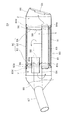
図3に、マフラー24の側面図において一部を断面にしたものを示す。
マフラー24は、マフラー24の各部を収容する外筒80と、外筒80に配置される内筒82と、内筒82の両端に取付けられマフラー24の内部を仕切る第1セパレータ83及び第2セパレータ84とを備えている。ここで、第1セパレータ83及び第2セパレータ84は内筒82の両端に溶接されている。外筒80の前部には、外筒80の前部を閉じるフロントキャップ85が溶接されて取付けられ、外筒80の後部には、外筒80の後部を閉じるエンドキャップ86が溶接されて取付けられている。
また、外筒80の横断面は略円形状であり、内部に収容される内筒82、第1セパレータ83及び第2セパレータ84も略円形状で構成されている。内筒82は、パンチングメタルが円筒状に巻かれて形成されたものである。
FIG. 3 shows a partial cross-sectional view of the
The
Further, the
マフラー24には、第1セパレータ83と第2セパレータ84とにより仕切られ、マフラー24の中央部に位置する第1膨張室X、フロントキャップ85と第1セパレータ83とにより仕切られ、マフラー24の前部に位置する第2膨張室Y、及び、第2セパレータ84とエンドキャップ86とにより仕切られ、マフラー24の後部に位置する第3膨張室Zが構成されている。
The
フロントキャップ85には、排気管23と接続されてエンジン5からの排気をマフラー24に導く第1排気管87が、第1セパレータ83の孔83aを貫通して、第1膨張室Xに連通されて取付けられている。第1排気管87は、フロントキャップ85との接続部で溶接により固定されており、第1セパレータ83の孔83aとの接続部では、溶接による固定はされていない。
第1セパレータ83には、第1排気管87が貫通する孔83aとずれた位置に孔83bが設けられ、この孔83bには、第1膨張室Xと第2膨張室Yとを連通する第2排気管88が孔83bを貫通して取付けられている。第2排気管88は、第1セパレータ83の孔83bとの接続部で溶接により固定されている。
第1セパレータ83には、孔83a及び孔83bと重ならない位置に、孔83cが設けられている。この孔83cと第2セパレータ84の孔84aとの間には、第1膨張室Xを跨いで第2膨張室Yと第3膨張室Zとを連通する第3排気管89が孔83cと孔84aとを貫通して取付けられている。第3排気管89は、第1セパレータ83の孔83cとの接続部では、圧入により固定され、第2セパレータ84の孔84aとの接続部では溶接による固定はされていない。また、第3膨張室Zを構成するエンドキャップ86には外部に通じる排気口93が設けられている。この排気口93には、排気の煤が外部に排出されることを防止するスパークアレスター(図示略)が取付けられている。
A
The
The
上記構成により、エンジン5から排出された排気ガスは、図3中、矢印で示すように、第1排気管87を通過してマフラー24内の第1膨張室Xに入った後、流れを反転し、第2排気管88を通過して第2膨張室Yに入り、再び流れを反転して第3排気管89を通過し、第3膨張室Zに入り、エンドキャップ86に設けられた排気口93から外部に排出される。このように、排気ガスが第1膨張室X、第2膨張室Y及び第3膨張室Zを通過して、各膨張室で膨張すると共に、マフラー24内で排気ガスの流れが複数回反転し排気経路が長くなる、いわゆる3パス構造をとっているので、マフラー24内で排気ガスの圧力が下げられ、排気音を低減することができる。
With the above configuration, the exhaust gas exhausted from the
このマフラー24は以下の手順で製造される。
図3に示すように、まず第1セパレータ83と第2セパレータ84とを、内筒82の両端に溶接して小組体90を構成し、ついで小組体90の各セパレータ83、84の外周部に外側から板材81を巻いて締め付け(以下、巻き締めという。)て、略円筒状の外筒80を形成し、外筒80の板材81の合わせ面100(図7)が溶接されて外筒80が閉じられる。そして、小組体90を収容した外筒80を閉じた後に、第1排気管87が取付けられたフロントキャップ85及び、エンドキャップ86が外筒80に溶接されて、マフラー24が製造される。
The
As shown in FIG. 3, first, the
第1セパレータ83及び第2セパレータ84は、図3及び図6に示すように、略皿形状の部材であり、大径部83d,84d及び小径部96を有している。大径部83d,84dの外径は、外筒80の内径と略同一寸法である。小径部96は、略円形状の大径部83d,84dよりも一段低くなって略皿形状の底部98の方向に形成され、小径部96の外径は内筒82の内径と略同一寸法である。小組体90は、内筒82の両端に、第1セパレータ83及び第2セパレータ84の略皿形状の底部98が対向する向きで、小径部96が嵌め込まれて配置され、溶接により接合されて形成される。
小組体90は外筒80の内部に収容され、第1セパレータ83は、第1セパレータ83の大径部83dと外筒80の内径とで嵌合されて取付けられており、一方、第2セパレータ84は、第2セパレータ84の大径部84dと外筒80の内径とで嵌合され、さらに、外筒80の外側からプラグ溶接されて固定されている。
なお、ここで、第2排気管88及び、第3排気管89を小組体90に組付けておけば、マフラー24の製作が容易であり、第3排気管89は、第1セパレータ83と第2セパレータ84とを貫通しているため、第3排気管89を組付けておけば、第1セパレータ83と第2セパレータ84との位置合わせが容易である。
また、外筒80と内筒82との間には、グラスウール等の吸音材91が配設され、マフラー24の消音能力が高められている。吸音材91は外筒80を巻き締めする前に、小組体90に配設される。
As shown in FIGS. 3 and 6, the
The
Here, if the
Further, a
図4に、マフラー24の側面図を示す。
マフラー24は、上記のように、小組体90が板材81で巻き締めされて略円筒状の外筒80が形成され、板材81の合わせ面100(図7)が溶接されて製作されるものであり、外筒80の軸方向と略平行な向きで、外筒80の合わせ面100(図7)の全体に亘って溶接部92が形成されている。また、フロントキャップ85と外筒80とは、接合部85aで外筒80の全周に亘り溶接され、エンドキャップ86と外筒80とは、接合部86aで外筒80の全周に亘り溶接されている。
FIG. 4 shows a side view of the
As described above, the
図5に、図4においてA−A線に沿った断面図を示す。
符号Cで示す部分は、溶接部92の断面であり、第1セパレータ83において溶接部92の下にあたる部分には、外周部が凹まされて形成された凹部95が形成されている。
図6に、図5において矢印Bの方向から見た第1セパレータ83を示す。
第1セパレータ83の外周には、凹部95が1箇所形成されており、凹部95の底面は略平坦である。
FIG. 5 is a cross-sectional view taken along line AA in FIG.
A portion indicated by a symbol C is a cross section of the welded
FIG. 6 shows the
One
図7に、図5の符号Cで示す部分を拡大して示す。
板材81が巻き締めされて形成された外筒80の合わせ面100は、板材81の一端81aが板材81の他端81bに潜り込んで重ねられて形成され、外筒80は、板材81の他端81bが溶接されて閉じられる。第1セパレータ83は、凹部95の中央が溶接部92に含まれる板材81の他端81bの下になる向きで外筒80に収容される。このように、溶接部92の下側には、凹部95が位置するため、溶接部92は、凹部95によりかわされて第1セパレータ83の大径部83dに接触せず、第1セパレータ83と外筒80とが溶接されることを防止できる。
FIG. 7 is an enlarged view of a portion indicated by reference numeral C in FIG.
The
凹部95の深さは、板材81の一端81aと他端81bとの板厚の和で構成される合わせ面100における外筒80の板厚よりもわずかに深く形成されている。また、合わせ面100において板材81が重なり合う長さは、凹部95における第1セパレータ83の外周方向の長さと同等である。
溶接部92の下に凹部95が位置するように位置合わせをする際は、凹部95を目印にして容易に位置合わせをすることができ、また、凹部95を溶接治具等との位置合わせに用いて、位置合わせを容易にすることもできる。
The depth of the
When positioning so that the
外筒80と凹部95との間の空間には、この空間を埋める栓部材97が配設されている。ここでは、栓部材97の材料は、内筒82の材料と同一のステンレスでメッシュ状のものが詰め込まれている。栓部材97の外寸及び板厚は、凹部95を埋められるように、凹部95と略同一であることが好ましい。この栓部材97により、第1セパレータ83の凹部95は埋められるため、凹部95から吸音材91が外部に飛散することを防止できる。
溶接部92の下には、栓部材97が配設されおり、栓部材97は、外筒80を閉じる溶接の際の熱や溶融部が、第1セパレータ83に直接触れることを防止できるため、第1セパレータ83と外筒80とが溶接されることがない。栓部材97は、外筒80を巻き締めする前に、凹部95に配置される。
In the space between the
A
マフラー24では、第1セパレータ83は、第1セパレータ83の大径部83dと外筒80の内周とで嵌合されて取付けられており、かつ、第1排気管87及び第3排気管89に対し溶接等により固定されていない。さらに、外筒80が巻き締め後に溶接により閉じられる際に、第1セパレータ83に凹部95が存在し、溶接部92が凹部95によりかわされて、第1セパレータ83の大径部83dに溶接部92が接触しないため、第1セパレータ83と外筒80とが溶接されることがない。このため、第1セパレータ83を備えた小組体90に対し、板材81で巻き締め後に溶接することで外筒80を形成しても、第1セパレータ83は、外筒80の内部で移動することができ、例えば、マフラー24の内部が高温になり、内筒82の膨張量が外筒80の膨張量よりも大きくなった場合に、内筒82は第1セパレータ83と共にマフラー24の軸方向に伸張でき、熱膨張によるひずみを吸収できる。
また、小組体90が外側から板材81により巻き締めされて、合わせ面100が溶接されて外筒80が形成されるので、小組体90を外筒80の内側に挿入する工程を省くことができ、小組体90の挿入のために行われていた外筒80の内側の溶接痕を取り除く作業が必要ないという利点がある。
In the
Further, since the
以上説明したように、本発明を適用した実施の形態によれば、内筒82と第1セパレータ83及び第2セパレータ84とを組立てた小組体90を外側から板材81で巻き締めして、合わせ面100を溶接して外筒80が形成され、第1セパレータ83は外筒80の溶接部92にかかる部分に凹部95を備えているため、外筒80の溶接部92が、外筒80の内径と略等しい外径を有した第1セパレータ83に形成された凹部95によってかわされて、外筒80と第1セパレータ83の大径部83dとが溶接で固着されることを防止できる。このため、外筒80の合わせ面溶接時に外筒80の内部で小組体90が外筒80に接合されることを防止できる。したがって、本構成では、小組体90の外側に板材81を巻き締め後溶接することで外筒80を形成した場合でも、外筒80の内部で第1セパレータ83が移動することでき、内筒82の熱膨張による伸長を吸収できる。
As described above, according to the embodiment to which the present invention is applied, the
また、第1セパレータ83の凹部95と外筒80との間を埋める栓部材97を設けたので、外筒80と前記内筒82との間に設けられたグラスウール等の吸音材91が、第1セパレータ83の凹部95と外筒80との間から外部に飛散することを防止できる。
In addition, since the
[第2の実施の形態]
図8は、本発明を適用した第2の実施の形態に係るマフラーの一部破断側面図である。図9は、マフラーの要部拡大断面図である。なお、この図9は、上記第1の実施の形態で説明した図7に相当する。
この第2の実施の形態において、上記第1の実施の形態と同様に構成される部分については、同符号を付して説明を省略する。
本第2の実施の形態におけるマフラー124では、図3に示したマフラー24とは異なり、小組体190が、内筒182と、この内筒182の両端に配置された第1セパレータ183及び第2セパレータ184とで構成されている。この小組体190の内筒182は、同径で延びる円筒部182aと、この円筒部182aの両端から拡径して筒状に延びる拡径部182b、182bとを一体に備え、円筒部182aの内径の両端に、第1セパレータ183及び第2セパレータ184が各々接合されて小組体190が構成される。
外筒180は、小組体190を組んだ後、小組体190が備える両拡径部182b、182bの外側から板材181が巻き締めされて形成され、外筒180の軸方向と略平行な向きで、板材181の合わせ面200が全体に亘って溶接されて、略円筒状とされたものである。この外筒180と内筒182との間には、グラスウール等の吸音材91が配設される。
[Second Embodiment]
FIG. 8 is a partially cutaway side view of a muffler according to a second embodiment to which the present invention is applied. FIG. 9 is an enlarged cross-sectional view of a main part of the muffler. FIG. 9 corresponds to FIG. 7 described in the first embodiment.
In the second embodiment, parts that are configured in the same manner as in the first embodiment are given the same reference numerals, and descriptions thereof are omitted.
In the
The
第1セパレータ183及び第2セパレータ184は、内筒182の円筒部182aの内径と略同径の外径部196を有し、略皿形状に形成されている。第1セパレータ183及び第2セパレータ184は、略皿形状の底部198が対向する向きで円筒部182aに嵌合され、外径部196が円筒部182aと溶接により接合される。
第1セパレータ183には、第1排気管87が貫通する孔183aとずれた位置に孔183b及び孔183cが設けられ、この孔183bを貫通するように、第1膨張室Xと第2膨張室Yとを連通する第2排気管88が取付けられ、孔183cを貫通するように、第1膨張室Xを跨いで第2膨張室Yと第3膨張室Zとを連通する第3排気管89が取付けられている。
第2セパレータ184には、第3排気管89が貫通する孔184aが設けられ、この穴84aを貫通するように、第3排気管89が取付けられている。これによって、エンジン5から排出された排気ガスが第1排気管87に入った後、流れを反転し、第2排気管88を通過して第2膨張室Yに入り、再び流れを反転して第3排気管89を通過し、第3膨張室Zに入り、エンドキャップ86に設けられた排気口93から外部に排出される。
The
The
The
本第2の実施の形態では、外筒180を構成する板材181が巻き締めされる内筒182の両拡径部182b、182bのうち、車体後側の拡径部182bは、プラグ溶接により外筒180に接合され、車体前側の拡径部182bは外筒180に溶接されない。すなわち、車体前側の拡径部182bには、板材181の合わせ面200に対応する溶接部192の下にあたる部分に、拡径部182bの略中心側に向けて凹む凹部195が設けられている。そして、この凹部195を設けることにより、合わせ面200と拡径部182bとが離間するので、合わせ面200の溶接時においても拡径部182bと外筒180とが溶接されるのを確実に防止できる。
また、この凹部195内には、メッシュ状の栓部材197が埋設され、この栓部材197により外筒180と内筒182の凹部195との間の空間が埋められるので、吸音材91の外部への飛散が防止される。ここで、栓部材197は、内筒182の材料と同一のステンレスで構成されるものとしてもよい。
In the second embodiment, among the
In addition, a mesh-shaped
このように、本第2の実施の形態によれば、合わせ面200の溶接時においても拡径部182bと外筒180とが溶接されるのを確実に防止できる。したがって、第1実施形態と同様に、外筒180の合わせ面溶接時に外筒180の内部で小組体190が外筒180に接合されることを防止できる。また、凹部195と外筒180との間を埋める栓部材197を設けたので、吸音材91の外部への飛散が防止される。
As described above, according to the second embodiment, it is possible to reliably prevent the
なお、上記実施の形態は本発明を適用した一態様であり、本発明は上記実施の形態に限定されないのは勿論である。例えば、上記実施の形態では、第1セパレータ83と第2セパレータ84とにより、マフラー24の内部が仕切られているが、本発明はこれに限定されるものではなく、分割された内筒82と第3のセパレータとで構成された小組体90を備え、2つのセパレータが外筒80の内部で移動可能な構成としても良い。
また、上記実施の形態では、栓部材97は、ステンレス製のメッシュ状のものを使用しているが、本発明はこれに限定されるものではなく、外筒80の溶接により容易に変質や溶融してしまうものでなければ栓部材97として用いることができる。
また、上述の実施形態では、四輪の鞍乗り型車両に本発明を適用する場合を説明したが、これに限らず、二輪車等の各種車両のマフラー構造に適用が可能である。
In addition, the said embodiment is one aspect to which this invention is applied, and of course, this invention is not limited to the said embodiment. For example, in the above embodiment, the inside of the
In the above embodiment, the
Moreover, although the case where this invention is applied to a four-wheel saddle-ride type vehicle was demonstrated in the above-mentioned embodiment, it is applicable not only to this but to the muffler structure of various vehicles, such as a two-wheeled vehicle.
1 鞍乗り型車両
4 車体フレーム
5 エンジン
23 排気管
24、124 マフラー
80、180 外筒
81,181 板材
81a、181a 一端
81b、181b 他端
82、182 内筒
83、183 第1セパレータ
83d、84d 大径部
84、184 第2セパレータ
87 第1排気管
88 第2排気管
89 第3排気管
90、190 小組体
91 吸音材
92、192 溶接部
93 排気口
95,195 凹部
96 小径部
97,197 栓部材
100,200 合わせ面
X 第1膨張室
Y 第2膨張室
Z 第3膨張室
1 Saddle-
Claims (4)
前記外筒は、前記小組体を外側から板材で巻き締めして、合わせ面を溶接して形成され、
前記小組体は前記外筒の溶接部にかかる部分に凹部を備えたことを特徴とする消音器構造。 In the silencer structure in which the inner cylinder and the separator are assembled in a small size and the small assembly is supported by the outer cylinder,
The outer cylinder is formed by winding the small assembly from the outside with a plate material and welding the mating surfaces,
The muffler structure according to claim 1, wherein the small assembly is provided with a recess in a portion of the outer cylinder that is in contact with the welded portion.
Priority Applications (2)
| Application Number | Priority Date | Filing Date | Title |
|---|---|---|---|
| JP2007226815A JP4670103B2 (en) | 2007-08-31 | 2007-08-31 | Silencer structure |
| US12/200,273 US7775321B2 (en) | 2007-08-31 | 2008-08-28 | Muffler structure |
Applications Claiming Priority (1)
| Application Number | Priority Date | Filing Date | Title |
|---|---|---|---|
| JP2007226815A JP4670103B2 (en) | 2007-08-31 | 2007-08-31 | Silencer structure |
Publications (2)
| Publication Number | Publication Date |
|---|---|
| JP2009057917A JP2009057917A (en) | 2009-03-19 |
| JP4670103B2 true JP4670103B2 (en) | 2011-04-13 |
Family
ID=40405648
Family Applications (1)
| Application Number | Title | Priority Date | Filing Date |
|---|---|---|---|
| JP2007226815A Expired - Fee Related JP4670103B2 (en) | 2007-08-31 | 2007-08-31 | Silencer structure |
Country Status (2)
| Country | Link |
|---|---|
| US (1) | US7775321B2 (en) |
| JP (1) | JP4670103B2 (en) |
Families Citing this family (5)
| Publication number | Priority date | Publication date | Assignee | Title |
|---|---|---|---|---|
| US8272468B2 (en) * | 2010-02-25 | 2012-09-25 | Yanmar Co., Ltd. | Work machine |
| JP5674849B2 (en) * | 2013-04-03 | 2015-02-25 | 三恵技研工業株式会社 | Silencer and manufacturing method thereof |
| JP6295496B2 (en) * | 2014-03-28 | 2018-03-20 | 本田技研工業株式会社 | Exhaust system |
| JP5997307B2 (en) * | 2015-02-25 | 2016-09-28 | 本田技研工業株式会社 | Exhaust structure of saddle-ride type vehicle |
| CN105257381B (en) * | 2015-09-30 | 2018-05-04 | 潍柴动力股份有限公司 | A kind of welding method of SCR system and its catalytic muffler and catalytic muffler |
Citations (3)
| Publication number | Priority date | Publication date | Assignee | Title |
|---|---|---|---|---|
| JP2004036528A (en) * | 2002-07-04 | 2004-02-05 | Shinba Iron Works Inc | Titanium exhaust muffler and its manufacturing method |
| JP2007016753A (en) * | 2005-07-11 | 2007-01-25 | Futaba Industrial Co Ltd | Method of manufacturing muffler for internal combustion engine |
| JP2008025452A (en) * | 2006-07-20 | 2008-02-07 | Sango Co Ltd | Muffler and method for manufacturing muffler |
Family Cites Families (17)
| Publication number | Priority date | Publication date | Assignee | Title |
|---|---|---|---|---|
| US2187431A (en) * | 1938-02-03 | 1940-01-16 | Herbert S Powell | Method of assembling mufflers |
| US3248791A (en) * | 1960-10-28 | 1966-05-03 | Walker Mfg Co | Method of manufacturing a muffler including coating with ceramic |
| US3507357A (en) * | 1968-05-09 | 1970-04-21 | James C Blome | Ceramic-coated mufflers and methods of making same |
| US4333545A (en) * | 1980-09-15 | 1982-06-08 | Thrush Incorporated | Back-fire resistant lock seam for muffler shells |
| US5100047A (en) * | 1988-06-25 | 1992-03-31 | Yukihiro Nakagawa | Spacing ring for tubes in high temperature environment |
| US5422445A (en) * | 1994-04-11 | 1995-06-06 | Midas International Corporation | Vehicular muffler having expansion joint |
| JP2967390B2 (en) * | 1994-04-21 | 1999-10-25 | 本田技研工業株式会社 | Muffler and manufacturing method thereof |
| US6247552B1 (en) * | 1994-12-16 | 2001-06-19 | J. Eberspächer Gmbh & Co. | Air gap-insulated exhaust manifold |
| DE19706386B4 (en) * | 1997-02-19 | 2006-03-16 | Daimlerchrysler Ag | Method for producing an air-gap-insulated exhaust manifold |
| JP3157742B2 (en) * | 1997-04-02 | 2001-04-16 | 株式会社三五 | Manufacturing method of silencer |
| JP3865917B2 (en) | 1998-01-23 | 2007-01-10 | カルソニックカンセイ株式会社 | Method and apparatus for manufacturing exhaust muffler for vehicle |
| WO2000001931A2 (en) * | 1998-07-07 | 2000-01-13 | Arvinmeritor, Inc. | Exhaust component having multiple-plated outer shell |
| US6405827B1 (en) * | 2000-05-10 | 2002-06-18 | Tenneco Automotive Operating Company Inc. | Lock seam for canisters |
| US6446322B1 (en) * | 2000-05-10 | 2002-09-10 | Tenneco Automotive Operating Company Inc. | Method and apparatus for sealing canisters |
| US7293628B2 (en) * | 2004-05-17 | 2007-11-13 | Calsonic Kansei Corporation | Shell main body for muffler |
| JP4454547B2 (en) | 2005-07-14 | 2010-04-21 | 本田技研工業株式会社 | Muffler structure |
| JP4545660B2 (en) * | 2005-09-02 | 2010-09-15 | カルソニックカンセイ株式会社 | Silencer structure |
-
2007
- 2007-08-31 JP JP2007226815A patent/JP4670103B2/en not_active Expired - Fee Related
-
2008
- 2008-08-28 US US12/200,273 patent/US7775321B2/en not_active Expired - Fee Related
Patent Citations (3)
| Publication number | Priority date | Publication date | Assignee | Title |
|---|---|---|---|---|
| JP2004036528A (en) * | 2002-07-04 | 2004-02-05 | Shinba Iron Works Inc | Titanium exhaust muffler and its manufacturing method |
| JP2007016753A (en) * | 2005-07-11 | 2007-01-25 | Futaba Industrial Co Ltd | Method of manufacturing muffler for internal combustion engine |
| JP2008025452A (en) * | 2006-07-20 | 2008-02-07 | Sango Co Ltd | Muffler and method for manufacturing muffler |
Also Published As
| Publication number | Publication date |
|---|---|
| JP2009057917A (en) | 2009-03-19 |
| US7775321B2 (en) | 2010-08-17 |
| US20090057055A1 (en) | 2009-03-05 |
Similar Documents
| Publication | Publication Date | Title |
|---|---|---|
| AU2005201864B2 (en) | Exhaust device for vehicle engine | |
| US7624842B2 (en) | Exhaust system for an engine and motorcycle including the exhaust system | |
| EP3061933B1 (en) | Exhaust structure of straddle-type vehicle | |
| JP4670103B2 (en) | Silencer structure | |
| EP2664761B1 (en) | Muffler unit for saddle-ride type vehicle | |
| US8136352B2 (en) | Cover member for plural exhaust pipes | |
| JP7155860B2 (en) | Silencer structure for straddle-type vehicle | |
| US11566546B2 (en) | Exhaust muffler structure | |
| JP5850816B2 (en) | Exhaust device for saddle riding type vehicle | |
| JP6303847B2 (en) | Exhaust gas sensor mounting structure for motorcycles | |
| JP7157110B2 (en) | Straddle type vehicle exhaust structure | |
| JP6292095B2 (en) | Exhaust device for saddle riding type vehicle | |
| EP2703616B1 (en) | Method of making a vehicle | |
| JP2012167569A (en) | Vehicular exhaust structure | |
| JP4381916B2 (en) | Silencer for internal combustion engine of motorcycle | |
| JP4785658B2 (en) | Scooter type motorcycle | |
| JP7045658B2 (en) | Motorcycle | |
| JP2008201171A (en) | Fuel tank and manufacturing method thereof | |
| JP2007056714A (en) | Exhaust device and vehicle equipped with the same | |
| JP4664937B2 (en) | Exhaust silencer / purifier | |
| JP2022120922A (en) | Saddle riding vehicle | |
| JP2010042707A (en) | Vehicle | |
| JP2019105245A (en) | Motor cycle | |
| JP2007030865A (en) | Vehicle frame, straddling type vehicle and method for manufacturing vehicle frame | |
| JP2016156316A (en) | Exhaust device of internal combustion engine |
Legal Events
| Date | Code | Title | Description |
|---|---|---|---|
| A621 | Written request for application examination |
Free format text: JAPANESE INTERMEDIATE CODE: A621 Effective date: 20091126 |
|
| A977 | Report on retrieval |
Free format text: JAPANESE INTERMEDIATE CODE: A971007 Effective date: 20101213 |
|
| TRDD | Decision of grant or rejection written | ||
| A01 | Written decision to grant a patent or to grant a registration (utility model) |
Free format text: JAPANESE INTERMEDIATE CODE: A01 Effective date: 20101221 |
|
| A01 | Written decision to grant a patent or to grant a registration (utility model) |
Free format text: JAPANESE INTERMEDIATE CODE: A01 |
|
| A61 | First payment of annual fees (during grant procedure) |
Free format text: JAPANESE INTERMEDIATE CODE: A61 Effective date: 20101228 |
|
| R150 | Certificate of patent or registration of utility model |
Ref document number: 4670103 Country of ref document: JP Free format text: JAPANESE INTERMEDIATE CODE: R150 Free format text: JAPANESE INTERMEDIATE CODE: R150 |
|
| FPAY | Renewal fee payment (event date is renewal date of database) |
Free format text: PAYMENT UNTIL: 20140128 Year of fee payment: 3 |
|
| LAPS | Cancellation because of no payment of annual fees |