JP4669256B2 - Torque converter - Google Patents
Torque converter Download PDFInfo
- Publication number
- JP4669256B2 JP4669256B2 JP2004279215A JP2004279215A JP4669256B2 JP 4669256 B2 JP4669256 B2 JP 4669256B2 JP 2004279215 A JP2004279215 A JP 2004279215A JP 2004279215 A JP2004279215 A JP 2004279215A JP 4669256 B2 JP4669256 B2 JP 4669256B2
- Authority
- JP
- Japan
- Prior art keywords
- pump
- torque converter
- blade
- turbine
- outer shell
- Prior art date
- Legal status (The legal status is an assumption and is not a legal conclusion. Google has not performed a legal analysis and makes no representation as to the accuracy of the status listed.)
- Active
Links
Images


Classifications
-
- F—MECHANICAL ENGINEERING; LIGHTING; HEATING; WEAPONS; BLASTING
- F16—ENGINEERING ELEMENTS AND UNITS; GENERAL MEASURES FOR PRODUCING AND MAINTAINING EFFECTIVE FUNCTIONING OF MACHINES OR INSTALLATIONS; THERMAL INSULATION IN GENERAL
- F16H—GEARING
- F16H41/00—Rotary fluid gearing of the hydrokinetic type
- F16H41/24—Details
- F16H41/26—Shape of runner blades or channels with respect to function
-
- F—MECHANICAL ENGINEERING; LIGHTING; HEATING; WEAPONS; BLASTING
- F16—ENGINEERING ELEMENTS AND UNITS; GENERAL MEASURES FOR PRODUCING AND MAINTAINING EFFECTIVE FUNCTIONING OF MACHINES OR INSTALLATIONS; THERMAL INSULATION IN GENERAL
- F16H—GEARING
- F16H45/00—Combinations of fluid gearings for conveying rotary motion with couplings or clutches
- F16H45/02—Combinations of fluid gearings for conveying rotary motion with couplings or clutches with mechanical clutches for bridging a fluid gearing of the hydrokinetic type
- F16H2045/0273—Combinations of fluid gearings for conveying rotary motion with couplings or clutches with mechanical clutches for bridging a fluid gearing of the hydrokinetic type characterised by the type of the friction surface of the lock-up clutch
- F16H2045/0284—Multiple disk type lock-up clutch
-
- F—MECHANICAL ENGINEERING; LIGHTING; HEATING; WEAPONS; BLASTING
- F16—ENGINEERING ELEMENTS AND UNITS; GENERAL MEASURES FOR PRODUCING AND MAINTAINING EFFECTIVE FUNCTIONING OF MACHINES OR INSTALLATIONS; THERMAL INSULATION IN GENERAL
- F16H—GEARING
- F16H45/00—Combinations of fluid gearings for conveying rotary motion with couplings or clutches
- F16H45/02—Combinations of fluid gearings for conveying rotary motion with couplings or clutches with mechanical clutches for bridging a fluid gearing of the hydrokinetic type
Description
本発明は、自動変速機等の駆動系列内に用いられるトルクコンバータに関し、特に、小型化が可能なトルクコンバータに関する。 The present invention relates to a torque converter used in a drive train such as an automatic transmission, and more particularly to a torque converter that can be downsized.
トルクコンバータにおいて、自動車やオートバイ等の機器への取付スペースの優位性(居住性、部品取付スペースの確保等)及び製造コストの低減から、小型化(小径化、偏平化)技術の開発が、従来からのテーマである。 In torque converters, the development of downsizing (smaller diameter, flattening) technology has been developed in the past due to the superior mounting space (living comfort, securing of parts mounting space, etc.) for equipment such as automobiles and motorcycles and the reduction of manufacturing costs. It is a theme from.
トルクコンバータの小型化を達成するための必要な条件の1つとして、トルクコンバータの特性の1つである容量係数C(入力トルク/入力回転数2)を速度比e(出力回転数/入力回転数)の全域に渡り向上させる、という条件がある。容量係数の向上は、主に、トルクコンバータにおけるブレード(ポンプブレード、タービンブレード、ステータブレード)形状、トーラス(外郭など)形状の工夫によりなされる。 As one of the necessary conditions for achieving the downsizing of the torque converter, the capacity coefficient C (input torque / input rotation speed 2 ), which is one of the characteristics of the torque converter, is set to the speed ratio e (output rotation speed / input rotation). There is a condition that it is improved over the whole number. The improvement of the capacity coefficient is mainly made by devising the shape of a blade (pump blade, turbine blade, stator blade) and torus (outer shape, etc.) in a torque converter.
容量係数を向上させるためのブレード形状の工夫に関し、近年、スーパーコンピュータの普及・パソコン能力の向上に伴い、3次元熱流体解析(Computational Fluid Dynamics;CFD)によってトルクコンバータの複雑なブレード形状に適用、解析することにより、成果を上げているという報告例がある(例えば、特許文献2参照)。 With regard to the contrivance of the blade shape to improve the capacity coefficient, it is applied to the complex blade shape of the torque converter by 3D thermal fluid dynamics (CFD) with the spread of supercomputers and the improvement of personal computer capability in recent years. There is a report example that results are obtained by analysis (see, for example, Patent Document 2).
しかし、パソコンの能力が向上したとはいえ、必要なトルクコンバータ特性を提示し、複雑なトルクコンバータブレード形状を求める所までは、現在の技術では不可能であり、ステータブレード単体での2次元形状に限定した報告例にとどまる。 However, even though the personal computer's performance has improved, it is impossible with current technology to present the necessary torque converter characteristics and to find a complicated torque converter blade shape. It is only a report example limited to.
然るに、設計者が設計したブレード形状の設定技術として、石原智男、V.J.JANDASEKらの1次元理論(非特許文献1、非特許文献2参照)がベースとなっているケースが多い。この理論によれば、ポンプブレードの出口角度は、−50°以上に設定されている。その理由は、この角度を越えると、前記1次元理論に基づく仮定が成立しなくなるからである(この理論によれば−68°が限界)。したがって、ポンプブレードの出口角度を−68°以下にすることは現実的にはありえなかった。ここで、ポンプブレードの出口角度に係る「−」(マイナス)という表現は、トルクコンバータをエンジン側から見て、エンジン回転軸に対しエンジンの回転方向側に傾いた状態を示したものである。
However, the blade shape setting technology designed by the designer is often based on the one-dimensional theory (see Non-Patent
また、トルクコンバータの小型化にあたって、容量係数を向上させる技術を追求していく過程において、中速度比域(速度比e=0.3〜0.7)の容量係数が、低速度比域(速度比e=0〜0.3)の容量係数より大きくなるといった問題が発生していた。このような問題は、自動車等の車両に適用した場合、車両発進時の加速の際(低速度比領域)にエンジン回転数の低下が発生し、加速フィーリングを損なう結果を生じる。これは、中速度比領域で高容量化すると、低速度比域での動作流体の(循環方向の)流速より中速度比域での動作流体の流速の方が大きくなるからである。 Further, in the process of pursuing a technology for improving the capacity coefficient in reducing the size of the torque converter, the capacity coefficient in the medium speed ratio range (speed ratio e = 0.3 to 0.7) is reduced to the low speed ratio range ( There has been a problem that the capacity coefficient of the speed ratio e = 0 to 0.3) becomes larger. When such a problem is applied to a vehicle such as an automobile, a decrease in engine speed occurs during acceleration (low speed ratio region) when the vehicle starts, resulting in a deterioration in acceleration feeling. This is because when the capacity is increased in the medium speed ratio region, the flow velocity of the working fluid in the medium speed ratio region becomes larger than the flow velocity (in the circulation direction) of the working fluid in the low speed ratio region.
一方、近年、3次元形状測定装置の発達やプレス精度の向上から様々な実験が可能となり、複雑な3次元形状のブレードの評価が可能となり、トーラス部の扁平率等を最適化することで、コンバータ内の摩擦損失や衝突損失の低減が可能となっている。発明者らは、従来形状は非現実的とされていたブレード形状のパラメータを変化させることで、トルクコンバータの高効率化を図れることに着目した。 On the other hand, in recent years, various experiments have become possible due to the development of three-dimensional shape measuring devices and the improvement of press accuracy, making it possible to evaluate blades with complicated three-dimensional shapes, and optimizing the flatness of the torus part, Friction loss and collision loss in the converter can be reduced. The inventors focused on the fact that the efficiency of the torque converter can be improved by changing the blade shape parameters, which have been considered unrealistic for the conventional shape.
本発明の第1の目的は、小型化が可能なトルクコンバータを提供することである。 A first object of the present invention is to provide a torque converter that can be miniaturized.
本発明の第2の目的は、低速度比領域(車両発進時)の加速フィーリングを向上させることができるトルクコンバータを提供することである。 The second object of the present invention is to provide a torque converter capable of improving the acceleration feeling in the low speed ratio region (when the vehicle starts).
本発明の一視点においては、アウタシェルとインナコアの間に配されたポンプブレードを有するポンプと、タービンブレードを有するタービンと、ステータと、を備えるトルクコンバータにおいて、前記ポンプブレードの出口角度は、前記ポンプブレードと前記アウタシェルとが当接する地点から前記ポンプブレードと前記インナコアとが当接する地点に渡り−90°より大きく−68°以下であり、前記ポンプブレードの形状は、前記ポンプブレードを入口部から出口部にかけて21等分した場合に、前記入口部から第1の部分乃至、第16の部分のそれぞれの部分にて前記ポンプの全運動量の1%以上4%以下を分担させ、かつ、前記入口部から第17の部分乃至第21の部分のそれぞれの部分にて前記ポンプの全運動量の平均7%以上15%以下を分担させるように構成されたことを特徴とする。
In one aspect of the present invention, in a torque converter including a pump having a pump blade disposed between an outer shell and an inner core, a turbine having a turbine blade, and a stator, the outlet angle of the pump blade is determined by the pump From the point where the blade and the outer shell abut to the point where the pump blade and the inner core abut, it is greater than -90 ° and less than or equal to -68 °. When the portion is divided into 21 equal parts, the first part to the sixteenth part from the inlet part share 1% to 4% of the total momentum of the pump, and the inlet part From the seventeenth part to the twenty-first part, an average of 7% or more of the total momentum of the
また、本発明の前記トルクコンバータにおいて、前記ポンプブレードの出口角度は、前記ポンプブレードと前記アウタシェルとが当接する地点から前記ポンプブレードと前記インナコアとが当接する地点に渡り−80°以上−75°以下であることが好ましい。 Further, in the torque converter of the present invention, the outlet angle of the pump blade ranges from −80 ° to −75 ° from the point where the pump blade and the outer shell contact to the point where the pump blade and the inner core contact. The following is preferable.
本発明によれば、ポンプ出口側の運動量変化が大きくなり、全体的に容量係数を向上させることができ、トルクコンバータの小型化が可能となる。 According to the onset bright, momentum changes in the pump outlet side is increased, it is possible to improve the overall capacity coefficient, it is possible to downsize the torque converter.
本発明によれば、ポンプブレードの出口角度を小さくすることで、トルク比及び効率を維持しながら、速度比の全般において容量係数が向上するが、トルクコンバータに与えるエネルギーに対し、中速度比域にての発生する動作流体の流速が限界となるため、相対的に中速度比領域での容量係数の上昇を抑えることが可能となり、低速度比領域(車両発進時など)の加速フィーリングを向上させることができる。 According to the present invention, by reducing the outlet angle of the pump blade, the capacity coefficient is improved in the overall speed ratio while maintaining the torque ratio and efficiency. Since the flow velocity of the working fluid generated at the limit is limited, it is possible to suppress the increase in the capacity coefficient in the medium speed ratio region, and to accelerate the low speed ratio region (such as when starting the vehicle). Can be improved.
本発明によれば、トルクコンバータにおける他の重要特性である、ストールトルク比と最高効率には影響を与えない。 According to the present invention, the stall torque ratio and the maximum efficiency, which are other important characteristics in the torque converter, are not affected.
本発明の実施形態1について図面を用いて説明する。図1は、本発明の実施形態1に係るトルクコンバータの構成を模式的に示した断面図である。図2は、本発明の実施形態1に係るトルクコンバータのポンプブレードの構成を示したインナコア当接部側から見たときの断面を模式的に示した図である。図3は、本発明の実施形態1に係るトルクコンバータのポンプブレードを21等分した場合の各分割部分と運動量分担率の関係を示したグラフである。図4は、本発明の実施形態1に係るトルクコンバータのポンプブレードの21等分の仕方を示した模式図である。
このトルクコンバータ1は、自動車用に自動変速機(図示せず)とともに用いられるものであり、フロントカバー10と、ポンプ20と、タービン30と、ステータ40と、ロックアップクラッチ50と、ダンパ機構60と、を有する。
This
フロントカバー10は、セットブロック11を介してエンジン(図示せず)に連結される。フロントカバー10は、深皿状に形成され、ポンプ20のアウタシェル22と接合する。なお、図示されていないエンジンは、図1の左側に配されることになる。
The
ポンプ20は、ステータ40から流入した流体をタービン30に送り込むための機械要素であり、ポンプブレード21と、アウタシェル22と、インナコア23と、ポンプハブ24と、を有する。ポンプブレード21は、アウタシェル22とインナコア23の間に配される。ポンプブレード21の詳細については後述する。アウタシェル22は、円環面がフロントカバー10の反対側に膨らんだ外郭部材である。アウタシェル22の外周端部は、フロントカバー10に連結して溶接一体化されている。アウタシェル22の内周面側には複数のポンプブレード21が植設されている。インナコア23は、ポンプブレード21の内縁側に取付けられている。ポンプハブ24は、アウタシェル22の内周端部に連結して溶接一体化されており、オイルポンプギヤ(図示せず)に連結される。ステータ40からタービン30に向って流入する流体は、エンジン駆動時、図1の矢印方向に示すようにしてポンプ20に流入するようになっている。
The
タービン30は、ポンプ20から送り込まれた流体の運動エネルギーを回転運動にかえ、回転動力を得るための機械要素であり、ポンプ20に対向して配され、タービンブレード31と、アウタシェル32と、インナコア33と、タービンハブ34と、を有する。タービンブレード31は、ポンプ20と対向させて配設され、アウタシェル32とインナコア33の間に配される。タービンブレード31の端面は、アウタシェル32とインナコア33に当接する。アウタシェル32は、円環面がフロントカバー10側に膨らんだ部分を有する外郭部材である。アウタシェル32の内周面側には複数のタービンブレード31が植設されている。アウタシェル32は、内周方向に屈曲延長されて、リベット35によりタービンハブ34に連結されている。インナコア33は、タービンブレード31の内縁側に取付けられている。タービンハブ34は、その内周のスプラインで自動変速機(図示せず)の入力軸(図示せず)に連結されている。タービンハブ34は、ダンパ機構60の構成部材、及びアウタシェル32とリベット35により連結一体化されている。
The
ステータ40は、タービン30側からポンプ20側に流れる流体を整流して還流するための機械要素であり、ポンプ20とタービン30の間に配設され、ワンウェイクラッチ41に支持されている。
The
ロックアップクラッチ50は、入力側のポンプ20と出力側のタービン30とを両者の回転差が小さいときに直結して動力を伝達する機械要素である。ロックアップクラッチ50は、ポンプ20とタービン30により構成されるトーラス部と軸方向に並べてフロントカバー10内に配置される。ロックアップクラッチ50は、ピストン51の動作により、ダンパ機構60を介してフロントカバー10を自動変速機(図示せず)の入力軸(図示せず)に係脱させる。
The lock-
ダンパ機構60は、ロックアップクラッチ50により入力側のポンプ20と出力側のタービン30とを直結したときのポンプ20とタービン30の回転差を吸収する機械要素である。ダンパ機構60は、タービン30とロックアップクラッチ50の間のスペースに配置されている。ダンパ機構60は、リベット52によりロックアップクラッチ50の構成部材に連結されており、リベット35によりタービンハブ34に連結されており、バネ61によってポンプ20とタービン30の回転差(ショック)を吸収する。
The
次に、実施形態1に係るトルクコンバータのポンプブレードの構成について詳細に説明する。 Next, the configuration of the pump blade of the torque converter according to the first embodiment will be described in detail.
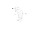
ポンプブレード21は、入口部21aと、出口部21bと、プレッシャ面21cと、サクション面21dと、アウタシェル当接部21eと、インナコア当接部21fと、を有する(図1及び図2参照)。入口部21aは、ステータ40から流れ込む流体の入口である。出口部21bは、ステータ40から流れ込んだ流体の出口である。プレッシャ面21cは、入口部21aと出口部21bとの間に形成されるとともに、ポンプ20側からタービン30側に流体が流れるように圧力を与える面である。サクション面21dは、入口部21aと出口部21bとの間に形成されるとともに、流体がポンプ20側からタービン30側に流体が流れるように吸引力を与える面であり、プレッシャ面21cの反対側の面である。アウタシェル当接部21eは、アウタシェル22と当接する境界部分である。インナコア当接部21fは、インナコア23と当接する境界部分である。
The
ポンプブレード21の出口角度は、出口部21bにおけるポンプブレード21とアウタシェル22とが当接する地点からポンプブレード21とインナコア23とが当接する地点に渡り、−90°より大きく−68°以下であり、好ましくは−80°以上−75°以下である。ここで、ポンプブレード21の出口角度とは、プレッシャ面21cとサクション面21dとの中心を入口部21aから出口部21bに亘って結ぶキャンバー線(面)Cの出口部21bに係る接線(接平面)Tと、トルクコンバータ1の回転軸に直交する直線(直平面)Lと、がなす角度αをいう(図2参照)。なお、ポンプブレードの出口角度に係る「−」(マイナス)という表現は、トルクコンバータ1をエンジン側(図1の左側)から見て、回転軸に対しエンジンの回転方向側に傾いた状態を示したものである。
The outlet angle of the
ポンプブレード21の形状は、ポンプブレード21を入口部21aから出口部21bにかけて21等分した場合に、入口部21aから第1の部分乃至、第16の部分のそれぞれの部分にて前記ポンプの全運動量の1%以上4%以下を分担させ、かつ、前記入口側から第17の部分乃至、第21の部分のそれぞれの部分にて前記ポンプの全運動量の平均7%以上15%以下を分担させるように構成される(図3参照)。ここで、21等分は、入口部21aから出口部21bにかけてアウタシェル当接部21eを21等分し、入口部21aから出口部21bにかけてインナコア当接部21fし、アウタシェル当接部21eで21等分された分点(分線)と、対応するインナコア当接部21fで21等分された分点(分線)と、を結ぶ直線(平面)によって分けたものである(図4参照)。よって、ポンプブレード21は、入口部21aから順に、第1の部分、第2の部分、……、第21の部分のように分けられる。
The shape of the
次に、実施形態1に係るトルクコンバータの特性について、従来例と比較しながら、図面を用いて説明する。図5は、本発明の実施形態1に係るトルクコンバータの特性を説明するためのグラフである。図5では、実線が従来例(ポンプブレードの出口角度が50°のトルクコンバータ)にかかるものを示し、点線が実施形態1にかかるものを示している。トルクコンバータの特性については、速度比eと容量係数Cの関係、速度比eと効率ηの関係、及び、速度比eとトルク比tの関係を示している。 Next, the characteristics of the torque converter according to the first embodiment will be described with reference to the drawings while comparing with the conventional example. FIG. 5 is a graph for explaining the characteristics of the torque converter according to the first embodiment of the present invention. In FIG. 5, the solid line shows the conventional example (torque converter with a pump blade outlet angle of 50 °), and the dotted line shows the one according to the first embodiment. Regarding the characteristics of the torque converter, the relationship between the speed ratio e and the capacity coefficient C, the relationship between the speed ratio e and the efficiency η, and the relationship between the speed ratio e and the torque ratio t are shown.
速度比の全領域において、トルク比tや効率ηについて、実施形態1と従来例には変化がない。一方、容量係数Cについて、実施形態1は、従来例と比較して、全般的に容量係数Cが向上しており、しかも中速度比領域(e=0.3〜0.7)において容量係数Cの向上が抑えられており、中速度比領域の容量係数Cよりも低速度比領域(e=0〜0.3)の容量係数Cの方が高い状態にある。 There is no change between the first embodiment and the conventional example with respect to the torque ratio t and the efficiency η in the entire region of the speed ratio. On the other hand, with respect to the capacity coefficient C, the capacity coefficient C is generally improved in the first embodiment as compared with the conventional example, and the capacity coefficient in the medium speed ratio region (e = 0.3 to 0.7). The improvement of C is suppressed, and the capacity coefficient C in the low speed ratio region (e = 0 to 0.3) is higher than the capacity coefficient C in the medium speed ratio region.
以上、本発明の実施形態について説明したが、本発明は上述した実施形態に限定される意図はなく、本発明の主旨に沿った形態のトルクコンバータであればどのような形態であってもよい。 As mentioned above, although embodiment of this invention was described, this invention is not intended to be limited to embodiment mentioned above, What kind of form may be sufficient if it is a torque converter of the form along the main point of this invention. .
実施形態1によれば、ポンプブレードの出口角度を小さくすることで、ポンプ出口側の運動量変化が大きくなり、全体的に容量係数を向上させることができ、トルクコンバータの小型化が可能となる。また、実施形態1によれば、トルク比及び効率を維持しながら、低速度比領域において、車両発進時の加速の際にエンジン回転数の低下が発生せず、加速フィーリングがよくなり、高速度比領域(e=0.7〜1.0)において、車両の追越加速性、通常走行時の静粛性等の車両動力性能、及び燃費性能が向上する。 According to the first embodiment, by reducing the outlet angle of the pump blade, the change in momentum on the pump outlet side can be increased, the capacity coefficient can be improved as a whole, and the torque converter can be downsized. Further, according to the first embodiment, while maintaining the torque ratio and the efficiency, in the low speed ratio region, the engine speed does not decrease during acceleration at the start of the vehicle, the acceleration feeling is improved, and the high In the speed ratio region (e = 0.7 to 1.0), vehicle acceleration performance such as overtaking acceleration of the vehicle, quietness during normal driving, and fuel efficiency are improved.
1 トルクコンバータ
10 フロントカバー
11 セットブロック
20 ポンプ
21 ポンプブレード
21a 入口部
21b 出口部
21c プレッシャ面
21d サクション面
21e アウタシェル当接部
21f インナコア当接部
22 アウタシェル
23 インナコア
24 ポンプハブ
30 タービン
31 タービンブレード
32 アウタシェル
33 インナコア
34 タービンハブ
35 リベット
40 ステータ
41 ワンウェイクラッチ
50 ロックアップクラッチ
51 ピストン
52 リベット
60 ダンパ機構
61 バネ
DESCRIPTION OF
Claims (2)
前記ポンプブレードの出口角度は、前記ポンプブレードと前記アウタシェルとが当接する地点から前記ポンプブレードと前記インナコアとが当接する地点に渡り−90°より大きく−68°以下であり、
前記ポンプブレードの形状は、前記ポンプブレードを入口部から出口部にかけて21等分した場合に、前記入口部から第1の部分乃至、第16の部分のそれぞれの部分にて前記ポンプの全運動量の1%以上4%以下を分担させ、かつ、前記入口部から第17の部分乃至第21の部分のそれぞれの部分にて前記ポンプの全運動量の平均7%以上15%以下を分担させるように構成されたことを特徴とするトルクコンバータ。 In a torque converter comprising: a pump having a pump blade disposed between an outer shell and an inner core; a turbine having a turbine blade; and a stator.
The outlet angle of the pump blade is greater than -90 ° and less than or equal to -68 ° from a point where the pump blade and the outer shell abut to a point where the pump blade and the inner core abut.
The shape of the pump blade is such that, when the pump blade is divided into 21 equal parts from the inlet portion to the outlet portion, the total momentum of the pump in each of the first portion to the sixteenth portion from the inlet portion. 1% or more and 4% or less are shared, and an average of 7% or more and 15% or less of the total momentum of the pump is shared by each of the 17th to 21st parts from the inlet. Torque converter characterized by being made.
Priority Applications (2)
| Application Number | Priority Date | Filing Date | Title |
|---|---|---|---|
| JP2004279215A JP4669256B2 (en) | 2004-09-27 | 2004-09-27 | Torque converter |
| US11/235,092 US7444807B2 (en) | 2004-09-27 | 2005-09-27 | Torque converter |
Applications Claiming Priority (1)
| Application Number | Priority Date | Filing Date | Title |
|---|---|---|---|
| JP2004279215A JP4669256B2 (en) | 2004-09-27 | 2004-09-27 | Torque converter |
Publications (2)
| Publication Number | Publication Date |
|---|---|
| JP2006090505A JP2006090505A (en) | 2006-04-06 |
| JP4669256B2 true JP4669256B2 (en) | 2011-04-13 |
Family
ID=36097457
Family Applications (1)
| Application Number | Title | Priority Date | Filing Date |
|---|---|---|---|
| JP2004279215A Active JP4669256B2 (en) | 2004-09-27 | 2004-09-27 | Torque converter |
Country Status (2)
| Country | Link |
|---|---|
| US (1) | US7444807B2 (en) |
| JP (1) | JP4669256B2 (en) |
Families Citing this family (8)
| Publication number | Priority date | Publication date | Assignee | Title |
|---|---|---|---|---|
| DE102008059264A1 (en) * | 2007-12-18 | 2009-06-25 | Luk Lamellen Und Kupplungsbau Beteiligungs Kg | Brazed assembly for torque converter pump hub and manufacturing process |
| JP4684321B2 (en) * | 2008-08-21 | 2011-05-18 | 株式会社エクセディ | Torque converter |
| CN101709771B (en) * | 2009-12-01 | 2012-05-30 | 陕西航天动力高科技股份有限公司 | Hydraulic torque converter for low-speed diesel engine |
| CN101994810B (en) * | 2009-12-07 | 2014-04-23 | 广西柳工机械股份有限公司 | Low-speed large-capacity twin-turbine torque converter |
| JP5012924B2 (en) * | 2010-02-05 | 2012-08-29 | トヨタ自動車株式会社 | Control device for vehicle power transmission device |
| JP5684515B2 (en) * | 2010-08-20 | 2015-03-11 | 株式会社エクセディ | Torque converter |
| CN103244633A (en) * | 2013-05-21 | 2013-08-14 | 广西柳工机械股份有限公司 | Double-turbine hydraulic torque converter |
| JP6572725B2 (en) * | 2015-10-19 | 2019-09-11 | アイシン精機株式会社 | Torque converter and manufacturing method thereof |
Citations (5)
| Publication number | Priority date | Publication date | Assignee | Title |
|---|---|---|---|---|
| JPH0579545A (en) * | 1991-05-10 | 1993-03-30 | Nissan Motor Co Ltd | Coreless torque converter |
| JPH05248510A (en) * | 1992-03-06 | 1993-09-24 | Aisin Seiki Co Ltd | Pump impeller for fluid type torque converter |
| JPH05263894A (en) * | 1992-03-19 | 1993-10-12 | Nissan Motor Co Ltd | Torque converter |
| JPH05322001A (en) * | 1992-05-18 | 1993-12-07 | Nissan Motor Co Ltd | Coreless torque converter |
| JPH0942412A (en) * | 1995-08-02 | 1997-02-14 | Katsuhiko Matsunami | Torque converter and adjusting method thereof |
Family Cites Families (4)
| Publication number | Priority date | Publication date | Assignee | Title |
|---|---|---|---|---|
| US2663148A (en) * | 1953-12-22 | Blading for hydraulic torque | ||
| DE2836332C2 (en) | 1978-08-19 | 1983-01-27 | Daimler-Benz Ag, 7000 Stuttgart | Blade of an impeller of a hydrodynamic torque converter |
| JP2945408B2 (en) | 1989-04-19 | 1999-09-06 | アイシン・エィ・ダブリュ株式会社 | Torque converter |
| JPH08326868A (en) * | 1995-06-05 | 1996-12-10 | Aisin Aw Co Ltd | Fluid transmitter |
-
2004
- 2004-09-27 JP JP2004279215A patent/JP4669256B2/en active Active
-
2005
- 2005-09-27 US US11/235,092 patent/US7444807B2/en active Active
Patent Citations (5)
| Publication number | Priority date | Publication date | Assignee | Title |
|---|---|---|---|---|
| JPH0579545A (en) * | 1991-05-10 | 1993-03-30 | Nissan Motor Co Ltd | Coreless torque converter |
| JPH05248510A (en) * | 1992-03-06 | 1993-09-24 | Aisin Seiki Co Ltd | Pump impeller for fluid type torque converter |
| JPH05263894A (en) * | 1992-03-19 | 1993-10-12 | Nissan Motor Co Ltd | Torque converter |
| JPH05322001A (en) * | 1992-05-18 | 1993-12-07 | Nissan Motor Co Ltd | Coreless torque converter |
| JPH0942412A (en) * | 1995-08-02 | 1997-02-14 | Katsuhiko Matsunami | Torque converter and adjusting method thereof |
Also Published As
| Publication number | Publication date |
|---|---|
| US7444807B2 (en) | 2008-11-04 |
| JP2006090505A (en) | 2006-04-06 |
| US20060064970A1 (en) | 2006-03-30 |
Similar Documents
| Publication | Publication Date | Title |
|---|---|---|
| JP2594388B2 (en) | Torque converter | |
| US7444807B2 (en) | Torque converter | |
| US7454902B2 (en) | Torque converter | |
| JP4773553B2 (en) | Lock-up device for torque converter | |
| JP2011122622A (en) | Lock-up device for torque converter | |
| US8596053B2 (en) | Fluidic torque transfer device | |
| JP3825219B2 (en) | Fluid torque transmission device | |
| JP4883921B2 (en) | Torque converter | |
| JP5950212B2 (en) | Stator structure of torque converter and method of manufacturing stator of torque converter | |
| JP2005054845A (en) | Damper mechanism for lock-up device | |
| JP2002544447A (en) | Hydrodynamic coupling device | |
| CN212509409U (en) | Hydrodynamic torque converter for a motor vehicle and motor vehicle comprising same | |
| JP5006063B2 (en) | Torque converter lockup damper mechanism | |
| JP4975482B2 (en) | Fluid coupling | |
| JP5258950B2 (en) | Torque converter | |
| JP5106555B2 (en) | Lock-up device for torque converter | |
| CN215720621U (en) | Torque converter | |
| JP2003106398A (en) | Torque converter | |
| JP2019138332A (en) | Torque converter | |
| JP6673009B2 (en) | Fluid torque transmission device | |
| JP3986412B2 (en) | Fluid torque transmission device | |
| JP4866757B2 (en) | Fluid torque transmission device | |
| CN115773345A (en) | Torque converter and method for manufacturing reactor provided in torque converter | |
| JP5052284B2 (en) | Impeller hub structure of torque converter | |
| JP2597551Y2 (en) | Torque converter |
Legal Events
| Date | Code | Title | Description |
|---|---|---|---|
| A621 | Written request for application examination |
Free format text: JAPANESE INTERMEDIATE CODE: A621 Effective date: 20070731 |
|
| A977 | Report on retrieval |
Free format text: JAPANESE INTERMEDIATE CODE: A971007 Effective date: 20100405 |
|
| A131 | Notification of reasons for refusal |
Free format text: JAPANESE INTERMEDIATE CODE: A131 Effective date: 20100803 |
|
| A521 | Request for written amendment filed |
Free format text: JAPANESE INTERMEDIATE CODE: A523 Effective date: 20100928 |
|
| A131 | Notification of reasons for refusal |
Free format text: JAPANESE INTERMEDIATE CODE: A131 Effective date: 20101102 |
|
| A521 | Request for written amendment filed |
Free format text: JAPANESE INTERMEDIATE CODE: A523 Effective date: 20101207 |
|
| TRDD | Decision of grant or rejection written | ||
| A01 | Written decision to grant a patent or to grant a registration (utility model) |
Free format text: JAPANESE INTERMEDIATE CODE: A01 Effective date: 20110104 |
|
| RD04 | Notification of resignation of power of attorney |
Free format text: JAPANESE INTERMEDIATE CODE: A7424 Effective date: 20110104 |
|
| A01 | Written decision to grant a patent or to grant a registration (utility model) |
Free format text: JAPANESE INTERMEDIATE CODE: A01 |
|
| A61 | First payment of annual fees (during grant procedure) |
Free format text: JAPANESE INTERMEDIATE CODE: A61 Effective date: 20110114 |
|
| FPAY | Renewal fee payment (event date is renewal date of database) |
Free format text: PAYMENT UNTIL: 20140121 Year of fee payment: 3 |
|
| R151 | Written notification of patent or utility model registration |
Ref document number: 4669256 Country of ref document: JP Free format text: JAPANESE INTERMEDIATE CODE: R151 |
|
| FPAY | Renewal fee payment (event date is renewal date of database) |
Free format text: PAYMENT UNTIL: 20140121 Year of fee payment: 3 |
|
| R250 | Receipt of annual fees |
Free format text: JAPANESE INTERMEDIATE CODE: R250 |
|
| R250 | Receipt of annual fees |
Free format text: JAPANESE INTERMEDIATE CODE: R250 |
|
| R250 | Receipt of annual fees |
Free format text: JAPANESE INTERMEDIATE CODE: R250 |
|
| R250 | Receipt of annual fees |
Free format text: JAPANESE INTERMEDIATE CODE: R250 |
|
| R250 | Receipt of annual fees |
Free format text: JAPANESE INTERMEDIATE CODE: R250 |
|
| R250 | Receipt of annual fees |
Free format text: JAPANESE INTERMEDIATE CODE: R250 |
|
| R250 | Receipt of annual fees |
Free format text: JAPANESE INTERMEDIATE CODE: R250 |