JP4664300B2 - Optical fiber ribbon with preferential tear - Google Patents
Optical fiber ribbon with preferential tear Download PDFInfo
- Publication number
- JP4664300B2 JP4664300B2 JP2006532291A JP2006532291A JP4664300B2 JP 4664300 B2 JP4664300 B2 JP 4664300B2 JP 2006532291 A JP2006532291 A JP 2006532291A JP 2006532291 A JP2006532291 A JP 2006532291A JP 4664300 B2 JP4664300 B2 JP 4664300B2
- Authority
- JP
- Japan
- Prior art keywords
- ribbon
- optical fiber
- intermediate portion
- subunits
- matrix
- Prior art date
- Legal status (The legal status is an assumption and is not a legal conclusion. Google has not performed a legal analysis and makes no representation as to the accuracy of the status listed.)
- Expired - Fee Related
Links
Images


Classifications
-
- G—PHYSICS
- G02—OPTICS
- G02B—OPTICAL ELEMENTS, SYSTEMS OR APPARATUS
- G02B6/00—Light guides; Structural details of arrangements comprising light guides and other optical elements, e.g. couplings
- G02B6/44—Mechanical structures for providing tensile strength and external protection for fibres, e.g. optical transmission cables
- G02B6/4401—Optical cables
- G02B6/4403—Optical cables with ribbon structure
- G02B6/4404—Multi-podded
-
- G—PHYSICS
- G02—OPTICS
- G02B—OPTICAL ELEMENTS, SYSTEMS OR APPARATUS
- G02B6/00—Light guides; Structural details of arrangements comprising light guides and other optical elements, e.g. couplings
- G02B6/44—Mechanical structures for providing tensile strength and external protection for fibres, e.g. optical transmission cables
- G02B6/4401—Optical cables
- G02B6/441—Optical cables built up from sub-bundles
- G02B6/4411—Matrix structure
Description
本発明は、概略的には光ファイバリボンに関する。より詳細には、本発明は、光ファイバリボンをサブユニットに分離するための優先引裂部分を有する光ファイバリボンに関する。 The present invention generally relates to optical fiber ribbons. More particularly, the present invention relates to an optical fiber ribbon having a preferential tear portion for separating the optical fiber ribbon into subunits.
光ファイバリボンは、光信号、例えば、音声、映像、及び/又はデータ情報を伝送する光ファイバのような光導波路を含む。光ファイバリボンを使用する光ファイバケーブルは、比較的高い光ファイバ密度をもたらすことができる。光ファイバリボンの構成は、一般的に、2つの一般的なカテゴリに分類することができ、すなわち、サブユニットを有する光ファイバリボンとそれを持たない光ファイバリボンである。サブユニットを有する光ファイバリボンの構成は、例えば、第1のサブユニットを形成する1次マトリックスによって取り囲まれた少なくとも1つの光ファイバを含み、第2のサブユニットも同様な構成を有し、これらは、2次マトリックスによって接触され、及び/又はそれによって封入される。他方、サブユニットを持たない光ファイバリボンは、一般的に、単一のマトリックス材料によって取り囲まれた複数の光ファイバを有する。 The fiber optic ribbon includes an optical waveguide, such as an optical fiber that transmits optical signals, eg, audio, video, and / or data information. Fiber optic cables that use fiber optic ribbons can provide a relatively high fiber optic density. Optical fiber ribbon configurations can generally be divided into two general categories: optical fiber ribbons with subunits and optical fiber ribbons without them. The configuration of the optical fiber ribbon having subunits includes, for example, at least one optical fiber surrounded by a primary matrix forming the first subunit, and the second subunit has a similar configuration, Are contacted and / or encapsulated by the secondary matrix. On the other hand, optical fiber ribbons without subunits typically have multiple optical fibers surrounded by a single matrix material.
光ファイバリボンは、例えば補強部材及びジャケットを有するマイクロケーブルと混同されるべきではない。例えば、米国特許第5,673,352号明細書は、コア構造とジャケットを有するマイクロケーブルを開示している。コア構造は、少なくとも1つの光ファイバが縦方向に延びる補強部材間に置かれ、その両方がバッファ材料に埋め込まれることを必要とする。ジャケットは、コア構造を保護し、その材料は、バッファ材料に対して良好な接着性を有し、耐磨耗性を有するように選択される。更に、補強部材は、光ファイバの直径よりも大きな直径を有し、それによってケーブルに加えられる破壊力を吸収することが要求される。 A fiber optic ribbon should not be confused with a microcable having, for example, a reinforcing member and a jacket. For example, US Pat. No. 5,673,352 discloses a microcable having a core structure and a jacket. The core structure requires that at least one optical fiber is placed between the longitudinally extending reinforcement members, both of which are embedded in the buffer material. The jacket protects the core structure and its material is selected to have good adhesion to the buffer material and wear resistance. Further, the reinforcing member is required to have a diameter larger than that of the optical fiber, thereby absorbing the breaking force applied to the cable.
他方、光ファイバリボンは、ほぼ平坦なアレイに配列されて比較的高い光ファイバ密度を形成する複数の隣接した光ファイバを有するのが一般的である。サブユニットを持たない光ファイバリボンは、当業者に対して問題を呈する可能性がある。例えば、これらの光ファイバリボンを光ファイバの部分集合に分離する際に、当業者は、高価な精密工具を使用しなくてはならない。更に、結合/接合手順は、光ファイバの様々な部分集合のための専用接合及び閉塞ユニット/ツールの常備を必要とする可能性がある。当業者が手作業又は妥当な精度を欠いた工具を使用して光ファイバリボンを部分集合に分離するように選択した場合、はぐれ光ファイバ及び/又は光ファイバの損傷が生じる可能性がある。はぐれ光ファイバは、光ファイバリボンの結合、編成、剥ぎ取り、及び接合に問題を引き起こす可能性がある。更に、光ファイバの損傷は望ましいことでなく、光ファイバをその意図された目的に対して作動不能にする可能性がある。 On the other hand, fiber optic ribbons typically have a plurality of adjacent optical fibers arranged in a substantially flat array to form a relatively high optical fiber density. Fiber optic ribbons without subunits can present problems for those skilled in the art. For example, in separating these optical fiber ribbons into optical fiber subsets, those skilled in the art must use expensive precision tools. Furthermore, the coupling / bonding procedure may require the provision of dedicated bonding and closure units / tools for various subsets of optical fibers. If one of ordinary skill in the art chooses to separate the fiber optic ribbon into subsets using hand tools or tools that lack reasonable accuracy, stray optical fibers and / or optical fiber damage may occur. Stripped optical fibers can cause problems in joining, knitting, stripping, and joining of optical fiber ribbons. In addition, damage to the optical fiber is undesirable and can render the optical fiber inoperable for its intended purpose.
しかし、サブユニットを使用することなく光ファイバリボンの分離を助けることを試みる光ファイバリボン構成が存在する。例えば、米国特許第5,982,968号明細書は、光ファイバリボンの長手方向軸線に沿って延びるV字状応力集中部をマトリックス材料内に有する均一な厚さの光ファイバリボンを必要とする。V字状応力集中部は、光ファイバリボンの平坦表面上に互いに対向して設けることができ、それによって光ファイバリボンの部分集合への分離を助けるものである。しかし、この第5,982,968号特許は、分離後のはぐれ光ファイバを回避するためにV字状応力集中部付近の光ファイバに隣接して付加的なマトリックス材料を要するので、より幅広の光ファイバリボンを必要とする。幅広のリボンは、より多くのマトリックス材料を必要とし、光ファイバ密度を低下させることになる。この特許の別の実施形態は、光ファイバの平面性のような幾何学形状の制御を改善するために、光ファイバの周りに第1のマトリックス材料の薄層を付加することを必要とする。次に、1次マトリックス材料の上に付加された2次マトリックス材料内にV字状応力集中部が形成され、それによって応力集中部における部分集合の分離を可能にする。 However, there are fiber optic ribbon configurations that attempt to help separate the fiber optic ribbons without using subunits. For example, U.S. Pat. No. 5,982,968 requires a uniform thickness optical fiber ribbon having a V-shaped stress concentrator in the matrix material that extends along the longitudinal axis of the optical fiber ribbon. . V-shaped stress concentrators can be provided on the flat surface of the optical fiber ribbon so as to oppose each other, thereby helping to separate the optical fiber ribbon into a subset. However, this 5,982,968 patent requires an additional matrix material adjacent to the optical fiber near the V-shaped stress concentrator to avoid the stray optical fiber after separation, so that the wider Requires an optical fiber ribbon. Wide ribbons require more matrix material and reduce optical fiber density. Another embodiment of this patent requires the addition of a thin layer of a first matrix material around the optical fiber to improve control of the geometry, such as the planarity of the optical fiber. Next, a V-shaped stress concentrator is formed in the secondary matrix material applied over the primary matrix material, thereby allowing separation of the subset in the stress concentrator.
分離可能な光ファイバリボンの別の例は、米国特許第5,970,196号明細書に説明されている。より具体的には、この第5,970,196号特許は、光ファイバリボンの平坦表面の各反対側に互いに対向して設けられたV字状切込み内に置かれた一対の取外し可能部分を必要とするものである。これらの取外し可能部分は、V字状切込みでの光ファイバリボンの部分集合への分離を容易にするために、光ファイバリボンの隣接した内部光ファイバ間に位置決めされる。取外し可能部分は、光ファイバリボンの平坦表面と面一とすることができ、又は平坦表面から突出してもよい。これら公知の光ファイバリボンは、いくつかの欠点を有する。例えば、それらはより高価であり、製造が困難である可能性がある。更に、作動性の観点から言えば、V字状応力集中部及び/又はV字状切込みは、光ファイバリボンの頑健性に望ましくない影響を及ぼし、及び/又は光ファイバに微細な曲げを引き起こす可能性がある。 Another example of a separable fiber optic ribbon is described in US Pat. No. 5,970,196. More specifically, this 5,970,196 patent includes a pair of removable portions placed in V-shaped cuts provided opposite each other on the flat surface of the optical fiber ribbon. It is what you need. These removable portions are positioned between adjacent internal optical fibers of the fiber optic ribbon to facilitate separation of the fiber optic ribbon into subsets with V-shaped cuts. The removable portion may be flush with the flat surface of the fiber optic ribbon or may protrude from the flat surface. These known optical fiber ribbons have several drawbacks. For example, they can be more expensive and difficult to manufacture. Furthermore, from an operability standpoint, V-shaped stress concentrations and / or V-shaped cuts can have an undesirable effect on the robustness of the optical fiber ribbon and / or cause fine bending in the optical fiber. There is sex.
分離を助けるためにサブユニットを使用する光ファイバリボンは、一般的にこれらの問題には遭遇しないが、他の問題点を有する可能性がある。図1は、2次マトリックス内に封入されたサブユニットを使用した従来の光ファイバリボン1を示すものである。サブユニットを有する光ファイバリボンは、いくつかの利点、例えば、改善された分離可能性及びはぐれファイバの発生回避を有することができる。特に、光ファイバリボン1は、1次マトリックス5内に封入された光ファイバ3を有する一対の従来のサブユニット2を含み、これらは、次に2次マトリックス4内に封入される。1次マトリックス5の厚さT1は、連続的かつ均一である。同様に、サブユニット2の平坦部分を被う2次マトリックス4の厚さt1も連続的かつ均一である。例えば、サブユニット2は、310μmの全体的に均一な厚さT1を有する1次マトリックス5内に置かれた6つの250μm光ファイバ3を含むことができ、2次マトリックス4は、330μmの全体的な光ファイバリボン厚さT2に対して10μmの厚さt1を有する。
Fiber optic ribbons that use subunits to assist in separation generally do not encounter these problems, but may have other problems. FIG. 1 shows a conventional optical fiber ribbon 1 using subunits enclosed in a secondary matrix. A fiber optic ribbon having subunits can have several advantages, such as improved separability and avoidance of stray fibers. In particular, the optical fiber ribbon 1 includes a pair of
しかし、従来の光ファイバリボン1は欠点を有する。例えば、1つの問題は、サブユニット2を手作業で分離する間のウイングW(図1)形成の可能性である。ウイングWは、例えば、共通マトリックス4とサブユニットマトリックス5の間に十分な接着力がないこと、及び/又は分離中の2次マトリックスのランダムな破断により生じる可能性がある。ウイングWの存在は、例えば、当業者による光リボン編成、結合、剥ぎ取り、及び/又は接合作業に悪影響を及ぼす可能性がある。更に、ウイングWは、リボン識別マーク付けの問題、又は、リボン処理工具、例えば、熱式ストリッパ、接合チャック、及び溶融接合装置とのサブユニットの適合性の問題を引き起こす可能性がある。
However, the conventional optical fiber ribbon 1 has drawbacks. For example, one problem is the possibility of forming a wing W (FIG. 1) while manually separating the
本発明は、第1のサブユニットと、第2のサブユニットと、第1及び第2のサブユニットの一部分に接触した2次マトリックスとを有する光ファイバリボンに関する。第1及び第2のサブユニットは、それぞれの1次マトリックスによって結合されて平面に沿ってほぼ整列したそれぞれの複数の光ファイバを含む。2次マトリックスは、少なくとも1つの端部分と少なくとも1つの中間部分を有する。この少なくとも1つの中間部分と少なくとも1つの端部分は、長手方向軸線の少なくとも一部分に沿ってギャップにより分離され、それによって優先引裂部分を形成する。 The present invention relates to an optical fiber ribbon having a first subunit, a second subunit, and a secondary matrix in contact with a portion of the first and second subunits. The first and second subunits include respective optical fibers that are coupled by respective primary matrices and are generally aligned along a plane. The secondary matrix has at least one end portion and at least one intermediate portion. The at least one intermediate portion and the at least one end portion are separated by a gap along at least a portion of the longitudinal axis, thereby forming a preferential tear portion.
本発明は、第1のサブユニットと、第2のサブユニットと、2次マトリックスとを含む光ファイバリボンにも関する。第1及び第2のサブユニットは、それぞれの1次マトリックスによって結合されたそれぞれの複数の光ファイバを含む。2次マトリックスは、両方とも所定の厚さを有する少なくとも1つの端部分と中間部分とを含む。中間部分は、第1及び第2サブユニット間の境界面に隣接して置かれる。更に、この少なくとも1つの端部分と少なくとも1つの中間部分は、リボンの長手方向軸線の少なくとも一部分に亘って離れ、中間部分の所定の厚さは、この少なくとも1つの端部分の所定の厚さよりも小さい。 The present invention also relates to an optical fiber ribbon that includes a first subunit, a second subunit, and a secondary matrix. The first and second subunits include respective optical fibers coupled by respective primary matrices. The secondary matrix includes at least one end portion and an intermediate portion, both having a predetermined thickness. The intermediate portion is placed adjacent to the interface between the first and second subunits. Further, the at least one end portion and the at least one intermediate portion are separated over at least a portion of the longitudinal axis of the ribbon, and the predetermined thickness of the intermediate portion is greater than the predetermined thickness of the at least one end portion. small.
本発明は、更に、第1のサブユニットと、第2のサブユニットと、第1及び第2のサブユニットの一部分に接触した2次マトリックスとを有し、かつ長手方向軸線を有する光ファイバリボンに関する。第1及び第2のサブユニットは、それぞれの1次マトリックスによって取り囲まれたそれぞれの複数の光ファイバを有する。2次マトリックスは、第1の端部分、第2の端部分、及び中間部分を有する。中間部分は、第1の端部分と第2の端部分の間に置かれる。第1の端部分は、長手方向軸線の少なくとも一部分に亘って第1のギャップにより中間部分から離れている。更に、第2の端部分は、長手方向軸線の少なくとも一部分に亘って第2のギャップにより中間部分から離れている。 The present invention further includes an optical fiber ribbon having a first subunit, a second subunit, a secondary matrix in contact with a portion of the first and second subunits, and having a longitudinal axis. About. The first and second subunits have respective optical fibers surrounded by respective primary matrices. The secondary matrix has a first end portion, a second end portion, and an intermediate portion. The intermediate portion is placed between the first end portion and the second end portion. The first end portion is separated from the intermediate portion by a first gap over at least a portion of the longitudinal axis. Further, the second end portion is separated from the intermediate portion by a second gap over at least a portion of the longitudinal axis.
次に、本発明の好ましい実施形態を示す添付図面を参照して、本発明を一層詳しく説明する。しかし、本発明は、多くの異なる形態で実施することができ、ここに示す実施形態に限定されると考えるべきではなく、これらの実施形態は、本明細書の開示が当業者に本発明の範囲を十分に伝えるように示すものである。図面は、必ずしも縮尺通りではなく、本発明を明確に示すように描かれている。 The present invention will now be described in more detail with reference to the accompanying drawings showing preferred embodiments of the invention. This invention may, however, be embodied in many different forms and should not be construed as limited to the embodiments set forth herein, which are disclosed by those skilled in the art of this disclosure. It is shown to convey the range sufficiently. The drawings are not necessarily to scale, but are drawn to clearly illustrate the present invention.
図2には、本発明による光ファイバリボン10が示されている。リボン10は、例えば、独立したリボンとして、リボンスタックの一部分として、又はより大きなリボンのサブユニットとして使用することができる。リボン10は、2次マトリックス15によって結合した2つのサブユニット13を含む。サブユニット13は、1次マトリックス14によって結合した複数の光ファイバ12を含む。一般的に、1次マトリックス14は、隣接する光ファイバをまとめて1つの細長い構造体として固定し、光ファイバ間の相対運動を抑制し、それによって工事作業及び取扱いに適する頑健なサブユニット13を提供するものである。1次マトリックス14は、サブユニット13のそれぞれの光ファイバ12を封じ込めた状態で示されているが、これは必ずしも必要ではない。2次マトリックス15は、少なくとも1つの端部分15aと少なくとも1つの中間部分15bを含む。中間部分15bは、一般的に、サブユニット13間の境界面上に置かれる。中間部分15bは、ほぼ平坦な平面を有するように示されているが、弓形又はV字形のような他の適切な形状を有することができる。この実施形態では、リボン10は、2つの端部分15aと、サブユニット13を互いに結合する1つの中間部分15bとを有し、それによって不均一な厚さを有する断面を形成する。具体的には、2次マトリックス15の中間部分15bは、端部分15aの少なくとも一方からリボン10の長手方向軸線の少なくとも一部分に亘ってギャップgによって離れている。ここで使用される「離れている」又は「ギャップ」という用語は、基本的には、下方に配置されたマトリックス上に2次マトリックス15がほとんど又は全く配置されないことを意味するが、薄膜のような微量の2次マトリックスが、この位置に配置されることはある。
FIG. 2 shows an
ここで使用されるサブユニットという用語は、その上に個別のマトリックス材料を有する複数の光ファイバを意味する。言い換えると、各サブユニットは、その上にそれ自体の個々のマトリックス材料を有する。サブユニットは、共通のマトリックス材料を有する群として配列された光ファイバである部分集合と混同されるべきでない。サブユニットが分離される時に、個別のマトリックス材料は、一般的に各サブユニットの光ファイバ上にそのままで残ることになる。更に、本発明の概念によるリボンは、そのリボン内で他の適切な数の光ファイバ及び/又はサブユニットを使用することができる。 As used herein, the term subunit means a plurality of optical fibers having individual matrix materials thereon. In other words, each subunit has its own individual matrix material on it. Subunits should not be confused with a subset of optical fibers arranged in groups having a common matrix material. As the subunits are separated, the individual matrix material will generally remain intact on the optical fiber of each subunit. Furthermore, ribbons according to the inventive concept can use any other suitable number of optical fibers and / or subunits within the ribbon.
図2に示す実施形態では、中間部分15bは、リボン10の長手方向軸線の少なくとも一部分に亘って両方の端部分15aから離れている。しかし、本発明の概念は、中間部分15bを一方の端部分15aからのみ離れていることも含む。好ましい実施形態では、中間部分15bは、リボンの長手方向軸線の大部分に沿って少なくとも1つの端部分15aから離れている。更に、中間部分15bは、ほぼ凸状のような任意の適切な形状を有することができる。中間部分15bと15aとの間にギャップgを設けることは、2次マトリックスのランダムな破断によるウイングの形成なしに、手作業によるサブユニット13の比較的容易な分離を可能にする。言い換えると、このギャップは、サブユニット13間に2次マトリックス15の優先引裂部分を提供する。更に、サブユニット13の分離後に、中間部分15bが、分離されたサブユニット13の一方に付加したままである場合には、それは、2次マトリックス15の端部分を裂き取ったり、引き裂いたり、又は除去することなく、このようなサブユニットから容易に取り除くことができる。すなわち、当業者は、迅速かつ効率的にサブユニットを手作業で分離することができる。
In the embodiment shown in FIG. 2, the
この実施形態では、中間部分15bは、端部分15aとほぼ同じ厚さを有する。しかし、他の実施形態は、中間部分15b及び/又はギャップgの寸法を望ましい性能特性が得られるように調整することができる。性能特性には、頑健性、捩れ性能、柔軟性、力の分離、及び/又は分離可能性が含まれる。例えば、本発明のリボンは、意図しない分離を起こすことなくある程度まで捩ることができるような優先的頑健性を有する。
In this embodiment, the
図3は、端部分15aに対して窪められた中間部分15bを有するリボン20を示すものである。例えば、中間部分15bは、少なくとも1つの端部分15aの主表面15cから全体で約3μm又はそれより大きい寸法だけ窪めることができるが、他の適切な窪みrの寸法も使用することができる。言い換えると、中間部分15bの各主表面15cは、全体で約3μmの窪みrを得るために、端部分15aの少なくとも1つの主表面15cによって形成される平坦表面から約1.5μm(r/2)下方にある。別の言い方をすると、少なくとも1つの端部分15aの厚さは、中間部分15bの厚さよりも大きい。別の実施形態では、中間部分15bの一方の側が中間部分の他の主表面よりも大きな窪みを有するように、窪みrは、主表面15c間で不均等に分割することができる。中間部分15bを説明する更に別の方法は、サブユニット13の平坦表面を基準とした中間部分15bの高い部分までの高さh(図示せず)である。別の実施形態では、中間部分15bは、少なくとも1つの端部分15aの主表面15cの一般的に上方である高さを有することができる。
FIG. 3 shows a
中間部分15bを窪ませることは、一般的に、サブユニット13間の境界面に近いサブユニット13の端部に伝達される力を低減し、それによって、例えば曲げたり及び/又は取扱い中に力が加えられた時に、境界面に隣接したサブユニット13の縁部ファイバ上における望ましくない光減衰を低減する。言い換えると、サブユニット間の境界面は応力点であり、そこでは、例えばリボンが撓んだり曲ったりして光減衰を引き起こす恐れのある縁部ファイバに圧縮力を加えるので、境界面に隣接したサブユニット13の縁部ファイバは、光減衰に対して敏感である。中間部分15bを窪ませることにより、サブユニット間の境界面に隣接した縁部ファイバに伝達される力が全体的に低減され、それによって縁部ファイバの光学性能が保たれるので、リボンの柔軟性及び/又は取扱い易さが全体的に改善される。
Recessing the
中間部分15bの幅wも望ましい性能を得るために調整することができる。例えば、幅wは、約600μm又はそれより小さくすることができるが、他の任意の寸法も使用することができる。材料の特性と共に幅w及び窪みrは、他の因子にも増してサブユニット13を分離するのに要する力に影響を及ぼすことができる。同様に、ギャップgの寸法は、柔軟性及び/又は取扱い易さのようなリボンの特性に影響することができる。例えば、ギャップgは、約3μm又はそれ以上の幅、好ましくは約5μm又はそれ以上の幅、最大で約600μmまでの幅を有することができるが、他の適切な寸法も使用することができる。更に、破断までの伸長及び/又は所定のマトリックス弾性係数のような適切な所定のマトリックス特性を使用することにより、リボンの優先引裂部分を強化することができる。
The width w of the
更に、本明細書においてその開示内容が引用により組み込まれている米国特許第6,253,013号に開示するように、1次マトリックスと2次マトリックスの間に接着区域18(図2)を使用することができる。接着区域18は、例えば、コロナ放電処理法を用いて1次マトリックス14に付加される。更に、リボンを識別するための標識を1次マトリックス又は2次マトリックス上に置くことができる。別の実施形態では、リボンを識別するために、2次マトリックスを使用することができる。例えば、リボンを識別するために、2次マトリックスを染料で着色することができる。
In addition, an adhesive zone 18 (FIG. 2) is used between the primary and secondary matrix as disclosed in US Pat. No. 6,253,013, the disclosure of which is incorporated herein by reference. can do. The bonded
本発明は、製造上の分散による断面表面に亘る起伏を有する従来のリボンと混同されるべきでない。これらの起伏は、例えば、所定位置における所定の形状ではなく、ランダムな位置で従来のリボンの厚さにおける変動を引き起こす可能性がある。例えば、従来のリボンの厚さは、断面を横切るランダムな位置で310±3μmとすることができる。他方、本発明によるリボンは、例えば、不均一な厚さ、すなわちギャップ、及び/又は分離性能を補助するために所定の位置において増加又は減少する中間部分を有することができる。 The present invention should not be confused with conventional ribbons having undulations across the cross-sectional surface due to manufacturing dispersion. These undulations can cause variations in the thickness of conventional ribbons at random locations, for example, rather than a predetermined shape at predetermined locations. For example, the thickness of a conventional ribbon can be 310 ± 3 μm at random positions across the cross section. On the other hand, ribbons according to the present invention can have, for example, non-uniform thickness, i.e. gaps, and / or intermediate portions that increase or decrease in place to aid in separation performance.
一実施形態では、光ファイバ12は、複数のシングルモード光ファイバであるが、他の種類又は構成の光ファイバも使用することができる。例えば、光ファイバ12は、マルチモード、ピュアモード、エルビウム添加、偏波保持ファイバ、他の適切な種類の光導波路、及び/又はその組合せも使用することができる。例えば、各光ファイバ12は、光を伝達するために働くことのできるシリカベースコアを含むことができ、シリカベースコアは、コアよりも低い屈折率を有するシリカベースの被覆によって取り囲まれる。更に、光ファイバ12には、1つ又はそれ以上のコーティングを設けることができる。例えば、柔らかい第1のコーティングが被覆を取り囲み、比較的剛性の第2のコーティングが第1のコーティングを取り囲む。コーティングは、識別のためのインク又は他の適切な標識、及び/又は識別手段の除去を阻止する接着防止剤を含むことができる。しかし、本発明のリボン内で使用される光ファイバは、一般的にタイトバッファではない。適切な光ファイバは、米国ニューヨーク州コーニング所在のコーニング・インコーポレーテッドから市販されている。
In one embodiment, the
1次マトリックス14は、例えば、放射硬化材料又は高分子材料としてもよいが、他の適切な材料も利用することができる。当業者には公知であるように、放射硬化材料は、所定の放射波長を照射された時に液体から固体へ転移する。硬化する前には、放射硬化材料は、例えば、液状モノマー、アクリレート官能基を有するオリゴマー「バックボーン」、フォトイニシエータ、及び他の添加物の調剤の混合物を含む。典型的なフォトイニシエータは、放射源により照射されたエネルギを吸収し、反応性化学種へと断片化し、次にモノマー及びオリゴマーの重合/硬化反応を開始することによって機能する。一般的に、照射の結果として、消滅し易い成分を含むと考えられるモノマーとオリゴマーの間に、硬化した固形の架橋ネットワークが形成される。言い換えると、フォトイニシエータは、弾性係数特性を有するほぼ固体のフィルムへの液状マトリックスの固化を促進する化学反応を開始する。
The
硬化処理の1つの態様は、放射露出に応答したフォトイニシエータの反応である。フォトイニシエータは、放射波長の関数として吸光度で測定される固有吸収スペクトルを有する。各フォトイニシエータは、独特の光活性領域、つまり一般的にナノメートル(nm)単位で測定される光活性波長領域を有する。例えば、市販のフォトイニシエータは、真空紫外線(160から220nm)、紫外線(220から400nm)、又は可視光(400から700nm)波長領域の光活性波長領域を有することができる。 One aspect of the curing process is a photoinitiator reaction in response to radiation exposure. The photoinitiator has an intrinsic absorption spectrum measured in absorbance as a function of emission wavelength. Each photoinitiator has a unique photoactive region, that is, a photoactive wavelength region, typically measured in nanometers (nm). For example, commercially available photoinitiators can have a photoactive wavelength region in the vacuum ultraviolet (160-220 nm), ultraviolet (220-400 nm), or visible (400-700 nm) wavelength region.
放射硬化材料の得られる弾性係数は、放射強度及び硬化時間のような因子により制御することができる。放射量つまり表面に到達する単位面積当たりの放射エネルギは、線速度つまり放射硬化材料が放射源を通過する速度に反比例する。光線量は、時間の関数としての照射パワーの積分値である。言い換えると、他の全ての条件が等しい場合には、線速度が早くなればなるほど、妥当な硬化を達成するためには放射強度が高くなくてはならない。放射硬化材料が十分に照射された後、その材料は硬化されたと呼ばれる。硬化は、放射硬化材料内において放射源に向う側から下に又は放射源から離れる方向に起こる。放射源により近い材料の部分は、放射が材料の未硬化部分に到達するのを妨げるので、硬化勾配が生じる可能性がある。入射放射の量に応じて、硬化された材料は、異なる硬化度を呈するであろう。更に、材料内の硬化の程度は、それに付随する個別の弾性係数特性をもたらす可能性がある。反対に、放射源は、材料が比較的均一な硬化度を有するように配置することができる。 The resulting elastic modulus of the radiation curable material can be controlled by factors such as radiation intensity and curing time. The amount of radiation, ie the radiant energy per unit area reaching the surface, is inversely proportional to the linear velocity, ie the speed at which the radiation curable material passes through the radiation source. The amount of light is an integral value of irradiation power as a function of time. In other words, if all other conditions are equal, the higher the linear velocity, the higher the radiation intensity must be to achieve reasonable cure. After the radiation curable material has been sufficiently irradiated, the material is said to be cured. Curing occurs in the radiation curable material from the side toward the radiation source down or away from the radiation source. The portion of the material that is closer to the radiation source prevents the radiation from reaching the uncured portion of the material, so a curing gradient can occur. Depending on the amount of incident radiation, the cured material will exhibit different degrees of cure. Furthermore, the degree of cure in the material can result in the individual modulus of elasticity properties associated therewith. Conversely, the radiation source can be arranged such that the material has a relatively uniform degree of cure.
すなわち、硬化の程度は、放射硬化材料の架橋密度を通して機械的特性に影響する。例えば、かなり硬化された材料は、その材料に対して高い架橋密度を有すると定めることができ、この材料は、例えば、過度に脆い。更に、硬化度の低い材料は、低い架橋密度を有する材料であると定めることができ、柔らかすぎて恐らく望ましくないレベルのリボン摩擦を引き起こす比較的高い摩擦係数(COF)を有することがある。紫外線硬化材料は、放射量に応じて、例えば約50MPaから約1500MPaの範囲内の弾性係数を有する。異なる弾性係数値は、例えば、本発明のリボンの手作業による分離可能性及び頑健性に関して様々な程度の性能を提供することができる。 That is, the degree of cure affects the mechanical properties through the crosslink density of the radiation curable material. For example, a highly cured material can be defined as having a high crosslink density for the material, which material is, for example, too brittle. Furthermore, a low cure material can be defined as a material having a low crosslink density and may have a relatively high coefficient of friction (COF) that is too soft and possibly causes an undesirable level of ribbon friction. The ultraviolet curable material has an elastic modulus in the range of about 50 MPa to about 1500 MPa, for example, depending on the amount of radiation. Different elastic modulus values can provide varying degrees of performance, for example, with regard to manual separability and robustness of the ribbons of the present invention.
一実施形態では、紫外線硬化材料は、1次マトリックス14のために使用される。例えば、紫外線硬化材料は、米国イリノイ州エルギン所在のDSM・デソテック・インコーポレーテッドから市販の950−706のようなポリウレタンアクリレート樹脂である。代替的に、例えば、米国オハイオ州コロンバス所在のボーデン・ケミカル・インコーポレーテッドから市販のポリエステルアクリレート樹脂のような他の適切な紫外線硬化材料も使用することができる。更に、ポリプロピレンのような熱可塑性材料もマトリックス材料として使用することができる。
In one embodiment, a UV curable material is used for the
更に、本発明によるリボンは、サブユニットの1次マトリックス14とは異なる接着性、COF特性、又は硬度のような材料特性を有する2次マトリックスを有することができる。これは、例えば、硬化特性のような異なる処理特性を有する1次マトリックスと類似の2次マトリックス材料を使用することにより、及び/又は1次マトリックスとは異なる材料を使用することにより達成することができる。同様に、2次マトリックスの異なる部分は、異なる材料を有し、及び/又は異なる材料特性を有することができ、それによって性能特性を調整することができる。
Furthermore, the ribbon according to the present invention may have a secondary matrix with material properties such as adhesion, COF properties, or hardness different from the
図4は、本発明によるリボンスタック40を示すものである。具体的には、リボンスタック40は、スタックを形成する複数のリボン30を含む。図に示すように、隣接したリボンの凹状部分は、互いに離れている。従って、凹状部分において隣接するリボンからの力の伝達は阻止される。例えば、圧縮力がリボンスタックに加えられた場合には、サブユニット境界面近くの縁部光ファイバは、隣接するリボンとの接触から隔離され、これらの光ファイバに応力が加えられるのを阻止する。本発明のいずれのリボンも、任意の適切な構成を有するリボンスタック内で使用することができる。更に、リボンスタックは、チューブ内に置くことができ、及び/又は光ファイバケーブルの一部分としてもよい。
FIG. 4 shows a
図5は、本発明の別の実施形態によるリボン50を示すものである。リボン50は、不均一な厚さを有する2次マトリックス55によって結合した6つのサブユニット13を含む。2次マトリックス55は、2つの端部分55a、第1の中間部分55b、第2の中間部分55c、及び中央区域55dを含む。中間部分55b及び55cは、一般的に、サブユニット13間の所定の境界面に亘って配置される。この実施形態では、リボン50は、第1の中間部分55bによって結合された第2及び第3のサブユニット13(左から右へ)と、第2の中間部分55cによって結合された第4及び第5のサブユニット13とを有する。更に、各端部分55aは、2つのサブユニット13を接触及び/又は結合しているが、別の実施形態では、端部分は、2つよりも多くのサブユニットを接触及び/又は結合することができる。しかし、他の実施形態では、中間部分は、必要に応じて他のサブユニット境界面の周りに置くことができる。第1及び第2の中間部分55b及び55cを図示のように置くことは、当業者がリボン50を3つのユニットに容易に分離することを可能にし、これらの各ユニットは、4つの光ファイバから成る2つのサブユニット内に8つの光ファイバを有する。その後、必要に応じて、当業者は、これら3つの個別的ユニットのいずれをも別々のサブユニットに分離することができる。言い換えると、リボン50は、最初に8つの光ファイバから成る3つのユニットへと引き裂くための最も強い優先度を有し、次に、必要に応じて、3つのユニットの各々を4つの光ファイバ単位に分離することができる。図に示すように、中央区域55dは、一般的に、第1の中間部分55bと第2の中間部分55cの間に置かれ、第3及び第4のサブユニットを互いに結合する。しかし、本発明の概念は、サブユニット及び/又は優先引裂部分の任意の適切な構成を使用することができる。
FIG. 5 shows a
説明の便宜上、2次マトリックス55の第1の中間部分55bと第2の中間部分55cは、異なる窪み寸法を有するが、好ましい実施形態は、同様な窪み寸法を備えた中間部分を有する。具体的には、第1の中間部分55bは、図に示すように少なくとも1つの端部分55aから窪んでおり、中央区域55dに対しても窪んでいる。他方、第2の中間部分55cは、一般的に何の窪みも有しない。同様に、上述のようにギャップg及び/又は第1の中間部分55bの幅wは、任意の適切な寸法を有し、それによってリボン50に望ましい性能特性を提供することができる。この場合、リボン50は、長手方向軸線の少なくとも一部分に亘って存在することができる複数のギャップgを有する。好ましい実施形態では、複数のギャップgは、リボン50の長手方向軸線の大部分に亘って存在する。
For convenience of explanation, the first
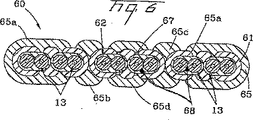
図6は、本発明の別の実施形態によるリボン60を示すものである。リボン60は、2次マトリックス61により結合された2つの光ファイバサブユニット13の6つを含み、それによって本発明の概念による複数の3つのリボン68を形成する。更に、リボン60は、2つの端部分65aと、第1の中間部分65bと、第2の中間部分65cと、中央区域65dとを有する3次マトリックス65を含む。中間部分65b及び65cは、一般的に、リボン68間の所定の境界面に亘って配置される。この実施形態では、リボン60は、第1の中間部分65bによって結合された第1及び第2のリボン68(左から右へ)と、第2の中間部分65cによって結合された第2及び第3のリボン68とを有する。しかし、他の実施形態では、必要に応じて中間部分を他のリボン境界面の周りに置くことができる。第1及び第2の中間部分65b及び65cを図示のように置くことは、当業者がリボン60を3つのリボンに容易に分離することを可能にし、これらの各リボンは、2つの光ファイバから成る2つのサブユニット内に4つの光ファイバを有することになる。すなわち、リボン60は、本発明の概念を使用した2つの別々のマトリックス61及び65を有する。更に、3次マトリックス65は、外側寄りの位置に示すようにリボン61のギャップを充填するか、又は中央位置に示すようにギャップに空隙67を残すように強いることができる。
FIG. 6 shows a
図7は、本発明による代表的な光ファイバケーブル70を示すものである。光ファイバケーブル70は、周りに覆い74を有するチューブ72内に置かれたリボンスタック40を含む。覆い74は、補強部材74aとジャケット74bを含む。図には単一チューブ光ファイバケーブル設計形状が示されているが、本発明は、溝付きコア、引込みケーブル、8字形、ルースチューブ、又は相互結合ケーブルのような任意の適切なケーブル設計形状を含むことができる。更に、光ファイバケーブル70又は任意の他の構成は、リップコード、防護層、結合剤層、補強部材、吸水膨張構成要素、防水材料、又は他の任意の適切なケーブル構成要素のようなより多く又はより少ないケーブル構成要素を含むことができる。
FIG. 7 shows an exemplary
当業者には、特許請求の範囲内で本発明の多くの変更及び他の実施形態が明らかになるであろう。例えば、サブユニットは、異なる数の光ファイバを含むことができ、リボンは、2つよりも多くのサブユニットを有することができ、又は、リボンは、他の適切な構成を有することができる。更に、本発明のリボンは、リボンスタックの一部であるか、又は他の適切な構成要素を含むことができる。従って、本発明は、ここに開示された特定的な実施形態に限定されるものではなく、特許請求の範囲内で変更及び他の実施形態を実施することができることは理解されるものとする。本明細書において特定の用語が使用されているが、それらは、包括的及び説明的な意味のみに使用されており、限定の目的で使用されているのではない。本発明は、シリカベース光ファイバを参照して説明したが、本発明の革新的概念は、他の適切な光導波路にも同様に適用可能である。 Many modifications and other embodiments of the invention will be apparent to those skilled in the art within the scope of the claims. For example, the subunits can include a different number of optical fibers, the ribbon can have more than two subunits, or the ribbon can have other suitable configurations. Further, the ribbons of the present invention can be part of a ribbon stack or include other suitable components. Accordingly, it is to be understood that the invention is not limited to the specific embodiments disclosed herein, and that modifications and other embodiments can be practiced within the scope of the claims. Although specific terms are used herein, they are used in a comprehensive and descriptive sense only and not for purposes of limitation. Although the present invention has been described with reference to a silica-based optical fiber, the innovative concepts of the present invention are equally applicable to other suitable optical waveguides.
Claims (2)
第1の1次マトリックスによって結合された第1の複数の光ファイバを含む第1のサブユニットと、
第2の1次マトリックスによって結合された第2の複数の光ファイバを含む第2のサブユニットと、を備え、
前記第1及び第2のサブユニットは、平面に沿ってほぼ整列し、
前記光ファイバリボンは、さらに、
少なくとも1つの端部分と、ギャップにより前記少なくとも1つの端部分と分離された少なくとも1つの中間部分を有し、かつ前記第1及び第2のサブユニットの一部分に接触した2次マトリックスを更に含み、
前記中間部分および前記少なくとも1つの端部分は前記ギャップの底部に対して隆起し、
前記少なくとも1つの中間部分は、前記少なくとも1つの端部分に対して窪み
前記少なくとも1つの中間部分は、前記第1のサブユニットと前記第2のサブユニットの間の境界面に亘って配置され前記第1のサブユニットと前記第2のサブユニットとを互いに連結し、
前記少なくとも1つの中間部分と前記少なくとも1つの端部分は、長手方向軸線の少なくとも一部分に沿ってギャップにより分離され、優先引裂部分を形成する、
ことを特徴とする光ファイバリボン。An optical fiber ribbon,
A first subunit comprising a first plurality of optical fibers coupled by a first primary matrix;
A second subunit comprising a second plurality of optical fibers coupled by a second primary matrix;
The first and second subunits are substantially aligned along a plane;
The optical fiber ribbon further includes:
A secondary matrix having at least one end portion and at least one intermediate portion separated from the at least one end portion by a gap and in contact with a portion of the first and second subunits;
The intermediate portion and the at least one end portion are raised relative to the bottom of the gap;
The at least one intermediate portion is recessed with respect to the at least one end portion. The at least one intermediate portion is disposed across an interface between the first subunit and the second subunit. Connecting the first subunit and the second subunit to each other;
The at least one intermediate portion and the at least one end portion are separated by a gap along at least a portion of a longitudinal axis to form a preferential tear portion;
An optical fiber ribbon characterized by that.
該第1の端部分と前記第2の端部分の両方は、長手方向軸線の大部分に亘って前記中間部分から離れている、
請求項1に記載の光ファイバリボン。The secondary matrix further includes a first end portion and a second end portion;
Both the first end portion and the second end portion are spaced from the intermediate portion over a majority of a longitudinal axis;
The optical fiber ribbon according to claim 1.
Applications Claiming Priority (2)
| Application Number | Priority Date | Filing Date | Title |
|---|---|---|---|
| US10/376,786 US6853783B2 (en) | 2003-02-28 | 2003-02-28 | Optical Fiber Ribbons Having Preferential Tear Portions |
| PCT/US2004/004926 WO2005008308A1 (en) | 2003-02-28 | 2004-02-18 | Optical fiber ribbons having preferential tear portions |
Publications (3)
| Publication Number | Publication Date |
|---|---|
| JP2006528798A JP2006528798A (en) | 2006-12-21 |
| JP2006528798A5 JP2006528798A5 (en) | 2007-04-05 |
| JP4664300B2 true JP4664300B2 (en) | 2011-04-06 |
Family
ID=32907999
Family Applications (1)
| Application Number | Title | Priority Date | Filing Date |
|---|---|---|---|
| JP2006532291A Expired - Fee Related JP4664300B2 (en) | 2003-02-28 | 2004-02-18 | Optical fiber ribbon with preferential tear |
Country Status (4)
| Country | Link |
|---|---|
| US (1) | US6853783B2 (en) |
| JP (1) | JP4664300B2 (en) |
| CN (1) | CN100399090C (en) |
| WO (1) | WO2005008308A1 (en) |
Families Citing this family (17)
| Publication number | Priority date | Publication date | Assignee | Title |
|---|---|---|---|---|
| US6792184B2 (en) * | 2002-05-31 | 2004-09-14 | Corning Cable Systems Llc | Optical fiber ribbons having a preferential separation sequence |
| EP1558957B1 (en) * | 2002-11-06 | 2010-04-21 | Sumitomo Electric Industries, Ltd. | Optical fiber ribbon and optical fiber cable using the same |
| US7471862B2 (en) * | 2002-12-19 | 2008-12-30 | Corning Cable Systems, Llc | Dry fiber optic cables and assemblies |
| US7415181B2 (en) * | 2005-07-29 | 2008-08-19 | Corning Cable Systems Llc | Fiber optic cables and assemblies for fiber to the subscriber applications |
| US7187830B2 (en) | 2004-12-22 | 2007-03-06 | Corning Cable Systems, Llc. | Optical fiber ribbons having a preferential tear portion formed by curing and methods therefor |
| US7251399B2 (en) * | 2005-03-17 | 2007-07-31 | Hewlett-Packard Development Company, L.P. | Method of making densely packed light guide ribbon |
| US7532796B2 (en) * | 2006-09-29 | 2009-05-12 | Corning Cable Systems Llc | Fiber optic ribbons having one or more predetermined fracture regions |
| US7274846B1 (en) * | 2006-09-29 | 2007-09-25 | Corning Cable Systems, Llc. | Fiber optic ribbon subunits having ends with different shapes |
| FR2942551B1 (en) * | 2009-02-23 | 2011-07-15 | Draka Comteq France | CABLE COMPRISING ELEMENTS TO BE EXTRACTED, METHOD OF EXTRACTING THESE ELEMENTS AND METHOD OF MANUFACTURING THE SAME |
| CA2769324A1 (en) | 2009-07-31 | 2011-02-03 | Corning Cable Systems Llc | Optical fiber cables |
| MX2018006558A (en) | 2015-11-30 | 2018-08-01 | Corning Optical Communications LLC | Flexible optical fiber ribbon with ribbon body flexibility recesses. |
| JP6490805B2 (en) * | 2015-12-01 | 2019-03-27 | 古河電気工業株式会社 | Optical fiber ribbon and optical fiber cable |
| US11256056B2 (en) * | 2016-04-08 | 2022-02-22 | Fujikura Ltd. | Method for manufacturing optical fiber ribbon, optical fiber ribbon, and optical cable |
| JP7063217B2 (en) * | 2018-09-27 | 2022-05-09 | 住友電気工業株式会社 | Optical fiber manufacturing method |
| US11442238B2 (en) | 2020-12-22 | 2022-09-13 | Prysmian S.P.A. | Optical-fiber ribbon with spaced optical-fiber units |
| US11860429B2 (en) | 2020-12-22 | 2024-01-02 | Prysmian S.P.A. | Optical-fiber ribbon with spaced optical-fiber units |
| US11460652B2 (en) | 2020-12-22 | 2022-10-04 | Prysmian S.P.A. | Optical-fiber ribbon with adhesive-free gaps |
Citations (3)
| Publication number | Priority date | Publication date | Assignee | Title |
|---|---|---|---|---|
| JP2000304989A (en) * | 1999-03-29 | 2000-11-02 | Siecor Operations Llc | Optical fiber array |
| JP2001350067A (en) * | 2000-04-06 | 2001-12-21 | Alcatel | Splittable optical fiber ribbon coupled at ends |
| JP2005528639A (en) * | 2002-05-31 | 2005-09-22 | コーニング ケーブル システムズ リミテッド ライアビリティ カンパニー | Optical fiber ribbon with non-uniform thickness and / or preferential tear |
Family Cites Families (41)
| Publication number | Priority date | Publication date | Assignee | Title |
|---|---|---|---|---|
| US4547040A (en) | 1983-06-21 | 1985-10-15 | Mitsubishi Rayon Co., Ltd. | Optical fiber assembly and process for preparing same |
| JPS60112203U (en) | 1984-01-05 | 1985-07-30 | 住友電気工業株式会社 | Multi-core fiber for optical transmission |
| DE3606617A1 (en) | 1986-02-28 | 1987-09-03 | Siemens Ag | FLAT TAPE LINE WITH SEVERAL LIGHTWAVE CORE AND METHOD FOR THE PRODUCTION THEREOF |
| DE3706323A1 (en) | 1987-02-27 | 1988-09-08 | Kabelmetal Electro Gmbh | TAPE LINE WITH FOCUS |
| JP2573632B2 (en) * | 1987-11-26 | 1997-01-22 | 住友電気工業株式会社 | Tape-type optical fiber manufacturing equipment |
| JPH01138518A (en) | 1987-11-26 | 1989-05-31 | Sumitomo Electric Ind Ltd | Tape-shaped optical fiber core |
| JP2533144B2 (en) | 1987-11-26 | 1996-09-11 | 住友電気工業株式会社 | Tape-shaped optical fiber |
| JPH01150106A (en) * | 1987-12-08 | 1989-06-13 | Sumitomo Electric Ind Ltd | Tape-shaped optical fiber |
| JP2820691B2 (en) | 1988-03-31 | 1998-11-05 | 株式会社フジクラ | Split type optical fiber tape |
| US4900126A (en) | 1988-06-30 | 1990-02-13 | American Telephone & Telegraph Co. | Bonded array of transmission media |
| US5208889A (en) * | 1991-10-24 | 1993-05-04 | W. L. Gore & Associates, Inc. | Optical fiber ribbon cable and assembly thereof with a connector |
| JP3314495B2 (en) | 1993-01-14 | 2002-08-12 | 住友電気工業株式会社 | Optical fiber ribbon |
| FI93152C (en) | 1993-04-05 | 1995-02-27 | Nokia Kaapeli Oy | Optical fiber tape |
| IT1271484B (en) | 1993-10-12 | 1997-05-28 | Alcatel Cavi Spa | MODULAR OPTICAL FIBER TAPE, SEPARABLE INTO A PLURALITY OF TAPES OR MODULES, PROCEDURE FOR MANUFACTURING SUCH TAPE AND OPTICAL CABLE USING THE SAME |
| JPH07120645A (en) | 1993-10-27 | 1995-05-12 | Mitsubishi Cable Ind Ltd | Optical fiber tape |
| JPH07318769A (en) * | 1994-05-18 | 1995-12-08 | Furukawa Electric Co Ltd:The | Coated optical fiber ribbon and optical fiber cable formed by using the coated optical fiber ribbon |
| US5457762A (en) | 1994-06-13 | 1995-10-10 | Siecor Corporation | Fiber optic ribbon |
| US5442722A (en) | 1994-07-25 | 1995-08-15 | Siecor Corporation | Optical fiber ribbon with zip cord |
| JPH08129122A (en) | 1994-10-31 | 1996-05-21 | Hitachi Cable Ltd | Optical fiber ribbon |
| JPH08262292A (en) | 1995-03-24 | 1996-10-11 | Fujikura Ltd | Coated optical fiber ribbon and optical cable formed by using the same |
| FR2735604B1 (en) | 1995-06-14 | 1997-07-18 | Schneider Electric Sa | FLAT CABLE AND STRIPPING PLIERS |
| JP4209943B2 (en) | 1995-08-01 | 2009-01-14 | コニンクリーケ デーエスエム ナムローゼ フェンノートシャップ | Ribbon unit, method of manufacturing ribbon unit, and method of providing midspan access |
| JPH09113773A (en) | 1995-10-24 | 1997-05-02 | Yazaki Corp | Coated optical fiber ribbon |
| US5673352A (en) | 1996-01-12 | 1997-09-30 | Alcatel Submarine Networks, Inc. | Fiber optic micro cable |
| JP3797496B2 (en) | 1996-01-17 | 2006-07-19 | 三菱電線工業株式会社 | Optical fiber tape manufacturing method |
| US5761363A (en) | 1996-03-07 | 1998-06-02 | Siecor Corporation | Optical fiber ribbon which is strippable and peelable |
| US5717805A (en) | 1996-06-12 | 1998-02-10 | Alcatel Na Cable Systems, Inc. | Stress concentrations in an optical fiber ribbon to facilitate separation of ribbon matrix material |
| US5933559A (en) | 1996-07-22 | 1999-08-03 | Dsm N.V. | Radiation-curable cross-linked ribbon matrix material for bonding an array of coated optical glass fibers |
| FR2752064B1 (en) | 1996-08-01 | 1998-09-04 | Alcatel Cable | MULTI-RIBBON OF FIBER OPTICS |
| TW420757B (en) | 1996-11-18 | 2001-02-01 | Sumitomo Electric Industries | Divided type optical fiber tape core wires |
| JPH09218328A (en) | 1997-01-09 | 1997-08-19 | Fujikura Ltd | Split optical fiber ribbon |
| US6195489B1 (en) | 1997-01-31 | 2001-02-27 | Fujikura Ltd. | Optical fiber cord, ribbon cord using the same and ribbon cord branch line |
| US5970196A (en) | 1997-09-22 | 1999-10-19 | Siecor Corporation | Fiber optic protective member with removable section to facilitate separation thereof |
| US6018605A (en) | 1997-12-31 | 2000-01-25 | Siecor Operations | Photoinitiator--tuned optical fiber and optical fiber ribbon and method of making the same |
| US6006000A (en) * | 1998-02-17 | 1999-12-21 | Hubbell Incorporated | Composite ribbon coupling cable for rotary coupling apparatus |
| US6175677B1 (en) * | 1998-04-17 | 2001-01-16 | Alcatel | Optical fiber multi-ribbon and method for making the same |
| US6097866A (en) | 1998-05-01 | 2000-08-01 | Alcatel | Optical fiber ribbon |
| JP4390160B2 (en) | 1998-06-26 | 2009-12-24 | 住友電気工業株式会社 | Batch coating die apparatus for manufacturing a split type optical fiber ribbon and manufacturing method |
| US6381390B1 (en) | 1999-04-06 | 2002-04-30 | Alcatel | Color-coded optical fiber ribbon and die for making the same |
| US6337941B1 (en) | 1999-09-29 | 2002-01-08 | Alcatel | Splittable optical fiber ribbons |
| KR100342503B1 (en) | 2000-08-30 | 2002-06-28 | 윤종용 | Ribbon optical fiber cable and coating die of ribbon optical fiber |
-
2003
- 2003-02-28 US US10/376,786 patent/US6853783B2/en not_active Expired - Lifetime
-
2004
- 2004-02-18 JP JP2006532291A patent/JP4664300B2/en not_active Expired - Fee Related
- 2004-02-18 CN CNB2004800054792A patent/CN100399090C/en not_active Expired - Fee Related
- 2004-02-18 WO PCT/US2004/004926 patent/WO2005008308A1/en active Application Filing
Patent Citations (3)
| Publication number | Priority date | Publication date | Assignee | Title |
|---|---|---|---|---|
| JP2000304989A (en) * | 1999-03-29 | 2000-11-02 | Siecor Operations Llc | Optical fiber array |
| JP2001350067A (en) * | 2000-04-06 | 2001-12-21 | Alcatel | Splittable optical fiber ribbon coupled at ends |
| JP2005528639A (en) * | 2002-05-31 | 2005-09-22 | コーニング ケーブル システムズ リミテッド ライアビリティ カンパニー | Optical fiber ribbon with non-uniform thickness and / or preferential tear |
Also Published As
| Publication number | Publication date |
|---|---|
| CN1777829A (en) | 2006-05-24 |
| US6853783B2 (en) | 2005-02-08 |
| JP2006528798A (en) | 2006-12-21 |
| CN100399090C (en) | 2008-07-02 |
| WO2005008308A1 (en) | 2005-01-27 |
| US20040170364A1 (en) | 2004-09-02 |
Similar Documents
| Publication | Publication Date | Title |
|---|---|---|
| US7085459B2 (en) | Optical fiber ribbons with subunits having preferential tear portions | |
| JP4664300B2 (en) | Optical fiber ribbon with preferential tear | |
| US7532796B2 (en) | Fiber optic ribbons having one or more predetermined fracture regions | |
| JP2008511869A (en) | Optical fiber ribbon with one or more preferential tearing portions and method of manufacturing | |
| US10007078B2 (en) | Optical fiber ribbon | |
| US6748148B2 (en) | Optical fiber ribbons having a non-uniform thickness and/or preferential tear portions | |
| US4900126A (en) | Bonded array of transmission media | |
| US6253013B1 (en) | Optical fiber arrays | |
| JP2008525846A (en) | Optical fiber ribbon having a preferentially torn portion formed by curing and method for manufacturing the same | |
| US6535673B1 (en) | Optical fiber arrays having an interface characteristic | |
| US11415769B2 (en) | Intermittent connection-type optical fiber tape core wire, optical fiber cable, and method for manufacturing intermittent connection-type optical fiber tape core wire | |
| US7274846B1 (en) | Fiber optic ribbon subunits having ends with different shapes |
Legal Events
| Date | Code | Title | Description |
|---|---|---|---|
| A521 | Request for written amendment filed |
Free format text: JAPANESE INTERMEDIATE CODE: A523 Effective date: 20070219 |
|
| A621 | Written request for application examination |
Free format text: JAPANESE INTERMEDIATE CODE: A621 Effective date: 20070219 |
|
| A131 | Notification of reasons for refusal |
Free format text: JAPANESE INTERMEDIATE CODE: A131 Effective date: 20090629 |
|
| A601 | Written request for extension of time |
Free format text: JAPANESE INTERMEDIATE CODE: A601 Effective date: 20090929 |
|
| A602 | Written permission of extension of time |
Free format text: JAPANESE INTERMEDIATE CODE: A602 Effective date: 20091006 |
|
| A521 | Request for written amendment filed |
Free format text: JAPANESE INTERMEDIATE CODE: A523 Effective date: 20100104 |
|
| A131 | Notification of reasons for refusal |
Free format text: JAPANESE INTERMEDIATE CODE: A131 Effective date: 20100208 |
|
| A601 | Written request for extension of time |
Free format text: JAPANESE INTERMEDIATE CODE: A601 Effective date: 20100428 |
|
| A602 | Written permission of extension of time |
Free format text: JAPANESE INTERMEDIATE CODE: A602 Effective date: 20100511 |
|
| A521 | Request for written amendment filed |
Free format text: JAPANESE INTERMEDIATE CODE: A523 Effective date: 20100802 |
|
| A131 | Notification of reasons for refusal |
Free format text: JAPANESE INTERMEDIATE CODE: A131 Effective date: 20100830 |
|
| A521 | Request for written amendment filed |
Free format text: JAPANESE INTERMEDIATE CODE: A523 Effective date: 20101125 |
|
| TRDD | Decision of grant or rejection written | ||
| A01 | Written decision to grant a patent or to grant a registration (utility model) |
Free format text: JAPANESE INTERMEDIATE CODE: A01 Effective date: 20101220 |
|
| A01 | Written decision to grant a patent or to grant a registration (utility model) |
Free format text: JAPANESE INTERMEDIATE CODE: A01 |
|
| A61 | First payment of annual fees (during grant procedure) |
Free format text: JAPANESE INTERMEDIATE CODE: A61 Effective date: 20110106 |
|
| R150 | Certificate of patent or registration of utility model |
Ref document number: 4664300 Country of ref document: JP Free format text: JAPANESE INTERMEDIATE CODE: R150 Free format text: JAPANESE INTERMEDIATE CODE: R150 |
|
| FPAY | Renewal fee payment (event date is renewal date of database) |
Free format text: PAYMENT UNTIL: 20140114 Year of fee payment: 3 |
|
| R250 | Receipt of annual fees |
Free format text: JAPANESE INTERMEDIATE CODE: R250 |
|
| R250 | Receipt of annual fees |
Free format text: JAPANESE INTERMEDIATE CODE: R250 |
|
| R250 | Receipt of annual fees |
Free format text: JAPANESE INTERMEDIATE CODE: R250 |
|
| R250 | Receipt of annual fees |
Free format text: JAPANESE INTERMEDIATE CODE: R250 |
|
| R250 | Receipt of annual fees |
Free format text: JAPANESE INTERMEDIATE CODE: R250 |
|
| LAPS | Cancellation because of no payment of annual fees |