JP4663433B2 - Image forming apparatus - Google Patents
Image forming apparatus Download PDFInfo
- Publication number
- JP4663433B2 JP4663433B2 JP2005203439A JP2005203439A JP4663433B2 JP 4663433 B2 JP4663433 B2 JP 4663433B2 JP 2005203439 A JP2005203439 A JP 2005203439A JP 2005203439 A JP2005203439 A JP 2005203439A JP 4663433 B2 JP4663433 B2 JP 4663433B2
- Authority
- JP
- Japan
- Prior art keywords
- recording medium
- electromagnetic wave
- pulse
- image forming
- medium
- Prior art date
- Legal status (The legal status is an assumption and is not a legal conclusion. Google has not performed a legal analysis and makes no representation as to the accuracy of the status listed.)
- Expired - Fee Related
Links
Images


Description
本発明は、プリンタ装置、複写機などの画像形成装置に関し、特には、高周波の電磁波によるセンシングにより、紙などの画像形成される記録媒体の種別、質、印字状態などの記録媒体の状態を判別して画像形成条件を設定する画像形成装置に関する。 The present invention relates to an image forming apparatus such as a printer or a copying machine, and in particular, the type, quality, and printing state of a recording medium on which an image is formed, such as paper, is determined by sensing using high-frequency electromagnetic waves. The present invention relates to an image forming apparatus for setting image forming conditions.
従来、複写機、インクジェットプリンタ、レーザプリンタなどの画像形成装置においては、印字する記録媒体(印字媒体)に応じて最適な画像を形成できるように画像形成条件の設定(印字動作条件の設定など)を行っている。その場合、印字媒体、具体的には普通紙、光沢紙、OHP用紙などを装置に設置した人間が、装置に対して紙種の設定をボタン操作などにより行うのが殆どである。 Conventionally, in image forming apparatuses such as copying machines, ink jet printers, and laser printers, setting of image forming conditions (setting of printing operation conditions, etc.) so that an optimal image can be formed according to a recording medium (printing medium) to be printed. It is carried out. In that case, a person who has installed a printing medium, specifically, plain paper, glossy paper, OHP paper, etc. in the apparatus mostly sets the paper type for the apparatus by operating a button.
この場合、紙種の設定の操作を間違えたときには、所望の画像が形成されなかったり、場合によっては印字をやり直すために、画像形成効率が低下したり、紙やインクの無駄になっていた。 In this case, when an operation for setting the paper type is wrong, a desired image is not formed, or in some cases, printing is performed again, so that the image forming efficiency is reduced or paper or ink is wasted.
これを解決するために、電磁波を用いて紙の種類や状態などを判別して印字動作条件の設定、画像形成動作などを自動的に行う画像形成装置が提案されている(特許文献1及び特許文献2参照)。また、電磁波を空間に伝播させて、重ねられた物体の表面または内部の画像情報などを透視して検知する媒体情報センシング装置やそれを用いた画像形成装置が提案されている(特許文献3参照)。
しかしながら、特許文献1及び特許文献2の提案例は、紙を透過してきた電磁波を用いて検知する透過型の紙種検知デバイスに関するものである。近年、複写機等の機器の小型化に伴って、各種デバイスも小型化が要求され、その設置スペースも限られてきている。そうした状況において、透過型の紙種検知デバイスであると、紙を挟み込むように電磁波の発生デバイスと電磁波の検出デバイスを配置することが必要になり、デバイスの設置できる場所が制限されることが考えられる。これにより、所望の場所で紙の種類や状態を検知できず、より高精細な画像を得られなくなる恐れが生じることが考えられる。また、特許文献3の提案例は、電磁波を用いて積層物体の状態を検知するが、その検知結果を基に物体に対する画像形成条件を設定するような装置とは異なる。
However, the proposed examples of
上記課題に鑑み、本発明の画像形成装置は、テラヘルツ領域の周波数を有する電磁波を発生させるための発生部と、積層された記録媒体で反射した前記電磁波を検出するための検出部と、前記記録媒体の種別を検出するための情報を予め記憶するための記憶部と、前記検出部を用いて得る前記反射した電磁波から得る信号をモニターして前記記録媒体の種別を検出するための情報を取得し、該取得した情報と前記記憶部が記憶する情報とを比較することにより、前記記録媒体の種別を検出するための演算部と、を有し、前記記録媒体の種別を検出するための情報は、前記信号が有しているパルスの強度が減少する割合および伝播遅延量を含み、前記演算部は、前記信号が有しているパルスを数えることにより、前記積層された記録媒体の厚さ方向に関する該記録媒体ごとの位置を取得し、前記信号が有しているパルスごとに前記記録媒体の種別を検出することを特徴とする。 In view of the above problems, an image forming apparatus of the present invention includes a generation unit for generating an electromagnetic wave having a frequency in the terahertz region, a detection unit for detecting the electromagnetic wave reflected by a stacked recording medium, and the recording Acquires information for detecting the type of the recording medium by monitoring a signal obtained from the reflected electromagnetic wave obtained by using the detection unit and a storage unit for previously storing information for detecting the type of the medium and, by the storage unit and the acquired information is compared with the information stored, anda calculation unit for detecting a type of the recording medium, information for detecting a type of the recording medium It is seen containing a rate and propagation delay intensity of pulses the signal has to decrease, the calculation unit, by counting the pulses the signal has, the thickness of the stacked recording medium The It acquires the position of each said recording medium relating to direction, and detects a type of the recording medium for each pulse the signal has.
上記の本発明の画像形成装置によれば、画像形成される記録媒体からの反射電磁波を用いるので、装置の設置スペースに対する制限を小さくでき、比較的柔軟に設置場所を設定できる画像形成装置を実現できる。 According to the above-described image forming apparatus of the present invention, since the reflected electromagnetic wave from the recording medium on which the image is formed is used, an image forming apparatus that can reduce the restriction on the installation space of the apparatus and can set the installation place relatively flexibly it can.
以下に、本発明による画像形成装置の一実施形態を説明する。本実施形態では、電磁波照射手段により、印字媒体などの記録媒体に30GHz〜30THzの周波数範囲の高周波の電磁波を照射する。この電磁波は、半値幅が10−12秒以下で前記周波数範囲のフーリエスペクトルを含んでいる連続的に発生する電磁波パルス、或いは前記周波数範囲で単一周波数を持つ連続的な高コヒーレンスの電磁波である。検出手段は、記録媒体の反射により伝播状態が変化した反射電磁波を検出する。一方、格納手段には、各種の記録媒体の状態に起因して伝播状態が変化する記録媒体からの反射電磁波のデータが格納されていて、判別手段は、前記格納されたデータと前記検出された反射電磁波の検出データとを比較して電磁波の照射された記録媒体の状態を判別する。そして、設定手段は、前記判別を基に該記録媒体に対する画像形成条件を自動的に最適に設定する。 Hereinafter, an embodiment of an image forming apparatus according to the present invention will be described. In this embodiment, the electromagnetic wave irradiation means irradiates a recording medium such as a printing medium with a high frequency electromagnetic wave in a frequency range of 30 GHz to 30 THz. This electromagnetic wave is a continuously generated electromagnetic pulse having a half width of 10 −12 seconds or less and including the Fourier spectrum in the frequency range, or a continuous high coherence electromagnetic wave having a single frequency in the frequency range. . The detecting means detects a reflected electromagnetic wave whose propagation state has changed due to reflection of the recording medium. On the other hand, the storage means, though data of the reflected electromagnetic wave from a recording medium in which the propagation state is changed due to the state of the various recording media are stored, determination means, is the detected and the stored data The state of the recording medium irradiated with the electromagnetic wave is determined by comparing with the detection data of the reflected electromagnetic wave. The setting means automatically sets the image forming conditions for the recording medium automatically and optimally based on the determination.
判別手段は、記録媒体の界面における反射電磁波の検出データを用いた前記比較により記録媒体の種別を判別したり、記録媒体の画像形成された部分の反射により伝播状態が変化した反射電磁波のデータと前記格納データとの比較により画像形成された部分の状態を判別したりする。画像形成される記録媒体が複数積層されている場合、判別手段が、各記録媒体の界面における反射電磁波の成分の検出データを用いた前記比較により各記録媒体の種別を判別し、設定手段が、この判別を基に各記録媒体に対する画像形成条件を自動的に最適に設定するようにもできる。判別手段が、前記比較により画像形成された部分の状態を判別する場合、設定手段は、この判別を基に画像形成される部分に対する画像形成条件を自動的にリアルタイムで最適に設定する。 The discriminating means discriminates the type of the recording medium by the comparison using the detection data of the reflected electromagnetic wave at the interface of the recording medium, or the reflected electromagnetic wave data whose propagation state has changed due to the reflection of the image formed portion of the recording medium. The state of the image-formed portion is determined by comparison with the stored data. When a plurality of recording media on which an image is formed are stacked, the determining means determines the type of each recording medium by the comparison using the detection data of the reflected electromagnetic wave component at the interface of each recording medium, and the setting means Based on this determination, the image forming conditions for each recording medium can be set automatically and optimally. When the determination unit determines the state of the image-formed part by the comparison, the setting unit automatically sets the image forming conditions for the image-formed part automatically and optimally in real time based on this determination.
本実施形態では、記録媒体の状態の読み取り用の電磁波としてミリ波〜テラヘルツ領域(30GHz〜30THz)のフーリエ周波数を含むものを用いる。テラヘルツ領域の電磁波を用いれば、印字媒体であるシート状の紙やプラスチックなどの透過性が高いために厚さ方向への伝播が可能であり、さらに物質の誘電率の変化によって反射、伝播遅延などが生じるために記録媒体の状態ないし性状に応じた情報を容易に取得することができる。 In the present embodiment, an electromagnetic wave that includes a Fourier frequency in the millimeter wave to terahertz region (30 GHz to 30 THz) is used as an electromagnetic wave for reading the state of the recording medium. By using electromagnetic waves in the terahertz region, it is possible to propagate in the thickness direction due to the high transparency of sheet-like paper and plastics, which are printing media, and reflection, propagation delay, etc. due to changes in the dielectric constant of the substance Therefore, information corresponding to the state or properties of the recording medium can be easily obtained.
紙などの状態ないし性状の情報は、反射電磁波を用いた場合に、シート状媒体の界面で反射してきた電磁波の遅延時間や振幅、波形などの変化として同定、区別することができる。シート状媒体が積層されていて電磁波パルスを用いる場合、シート状媒体の厚さ方向の箇所の検知は、放射した電磁波の反射エコーを観察することで行うことができる。電磁波として0.4psec程度の半値幅を持つパルスを用い、そのパルス幅の1/2までパルスの分離が行えるとすれば、0.2psecの遅延時間τに相当する距離dは次式より次の様に求まる。
d=τc/2 (c:光速) (1)
すなわち、d=30μmと求まるので、この程度の厚さのシート状媒体まで薄いものも1枚ずつ状態ないし性状の情報を読み取ることができる。こうして、厚さ方向に、30μm程度のシート毎の種別などの検査などを行うことができる。この厚さ方向の箇所の情報は、後述する実施例で述べるように遅延回路の掃引により読み取ることができる。
Information on the state or property of paper or the like can be identified and distinguished as changes in the delay time, amplitude, waveform, etc. of the electromagnetic wave reflected at the interface of the sheet-like medium when the reflected electromagnetic wave is used. When the sheet-like medium is laminated and an electromagnetic wave pulse is used, the detection of the location in the thickness direction of the sheet-like medium can be performed by observing the reflected echo of the emitted electromagnetic wave. If a pulse with a half-value width of about 0.4 psec is used as the electromagnetic wave and the pulse can be separated to half of the pulse width, the distance d corresponding to the delay time τ of 0.2 psec is as follows from the following equation: I want.
d = τc / 2 (c: speed of light) (1)
That is, since d = 30 μm is obtained, it is possible to read information on the state or properties of even a thin sheet of medium thickness such as this one by one. In this way, it is possible to inspect the type of each sheet of about 30 μm in the thickness direction. Information on the location in the thickness direction can be read by sweeping the delay circuit as will be described in an embodiment described later.
電磁波が、前記周波数範囲で単一周波数を持つ連続的な電磁波である場合は、検出器側では発振側の電磁波を参照波として受信信号とのミキシングを行ってフーリエ変換による波形解析を行い、記録媒体からの反射電磁波の参照波に対する伝播状態の変化を検出する。前記波形解析として干渉計測などの手段を用いてもよい。積層された記録媒体からの電磁波である場合は、記録媒体の枚数に応じて位相のずれた複数の電磁波が反射電磁波に混合されているので、検出器側では発振側の電磁波を少しずつ遅延してずらして行って参照波とし、各参照波と受信信号とのミキシングを行ってフーリエ変換による波形解析を行い、各記録媒体からの電磁波の伝播状態の変化を検出する。この場合も、波形解析として干渉計測などの手段を用いてもよい。また、記録媒体は、紙やプラスチック以外にも、すでに印字や画像形成された紙やプラスチックでもよい。インクやトナーの付着状態によっても電磁波の状態が変化し、それを検出することにより、より的確な画像形成が可能になる。 When the electromagnetic wave is a continuous electromagnetic wave having a single frequency in the frequency range, the detector side performs mixing with the received signal using the oscillation side electromagnetic wave as a reference wave, performs waveform analysis by Fourier transform, and records Changes in the propagation state of the reflected electromagnetic wave from the medium with respect to the reference wave are detected. Means such as interference measurement may be used as the waveform analysis. In the case of electromagnetic waves from a laminated recording medium, a plurality of electromagnetic waves whose phases are shifted according to the number of recording media are mixed with the reflected electromagnetic waves. The reference wave is shifted to make a reference wave, each reference wave and the received signal are mixed, and a waveform analysis is performed by Fourier transform to detect a change in the propagation state of the electromagnetic wave from each recording medium. Also in this case, means such as interference measurement may be used as the waveform analysis. In addition to paper and plastic, the recording medium may be paper or plastic on which printing or image formation has already been performed. The state of electromagnetic waves also changes depending on the state of adhesion of ink or toner, and by detecting this, more accurate image formation becomes possible.
以下に、高周波の電磁波を用いた本発明の画像形成装置の実施例について図面を用いて説明する。ただし、材料、構造、デバイス、方式などはここに挙げたものに限定するものではない。 Embodiments of the image forming apparatus of the present invention using high-frequency electromagnetic waves will be described below with reference to the drawings. However, materials, structures, devices, systems, etc. are not limited to those listed here.
(実施例1)
本発明の実施例1について説明する。実施例1の画像形成装置では、複数枚の紙などの記録媒体である印字媒体の種別を判別して、その結果を基に媒体に対する画像形成条件を最適に設定する。本実施例の装置の原理を図1、図2を用いて説明する。シート状の物体1である印字媒体が図1に示すように複数枚重ねられた状態で、その種別が判別される場合を考える。
Example 1
Example 1 of the present invention will be described. In the image forming apparatus according to the first exemplary embodiment, the type of a printing medium that is a recording medium such as a plurality of sheets is determined, and an image forming condition for the medium is optimally set based on the result. The principle of the apparatus of this embodiment will be described with reference to FIGS. Consider a case in which the type is determined in a state where a plurality of print media as sheet-
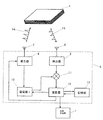
画像形成装置の電磁波送受信部を含む媒体情報センシング部5は、電磁波パルス発生器6、電磁波パルス14を空間に放出するアンテナ7、シート状媒体1からの反射パルス15を受信するアンテナ9および検出器8、発生器6からのパルスの発生タイミングを遅延させる遅延器10、遅延された発信パルスと受信パルスをミキシングするミキサ11、実際に遅延時間τを基に各シート状媒体1の距離を同定、区別してその種別を判別し画像形成条件の設定に関する信号を出力する演算器12を有する。また、シート状媒体1である普通紙、カラーコピー用紙、光沢紙、OHP用シートなどの反射による電磁波パルスの波形変化などの伝播状態の変化のデータをメモリしておく記憶部13が演算部12からランダムアクセスできるようになっている。これらは1つの筐体内に一体化したり、集積化したりすることができるが、必ずしも全てが1つに収められていなくてもよい。
The medium
ミキサ11の出力は、発信パルスを時間遅延させた信号と受信パルスのタイミングが一致したところで最大出力が得られるようになっている。したがって、演算器12によって、遅延器10による遅延量を掃引制御しながら、出力をモニタすることで、電磁波の伝播遅延時間を同定して各シート状媒体1までの距離とそれからの受信波形を検知しその種別を演算部12からのデータを参照して判別できる。このとき発生器6からの電磁波パルスの出力を100kHzオーダーの低周波で変動させておき、ミキサ11の出力をさらにその低周波信号とのミキシング出力として取り出す周知の同期検波技術を用いてもよい。
As for the output of the
演算器12では、さらに、上記種別の判別を基に、各シート状媒体1に対する印字動作条件の設定に関する信号を生成して、適宜、画像形成部2に出力する。画像形成部2では、演算器12からの信号に基づいて印字動作条件を設定したり、或いは設定し直したりして、各シート状媒体1に対して印字動作を実行する。印字動作条件としては、インクジェットプリンタなどの場合、ノズルからのインクの吐出圧、印字速度、印字媒体とノズル間の距離などがあり、レーザビームプリンタや複写機などの場合、印字媒体に対するトナーの定着温度、定着圧力、ドラムへの印加電圧などがある。
The
上記構成において、電磁波パルス発生器6とアンテナ7が電磁波照射手段に対応し、アンテナ9と検出器8と遅延器10とミキサ11が検出手段に対応し、記憶部13が格納手段に対応し、演算器12が判別手段及び設定手段に対応する。演算器12側から設定手段の機能をなくして、画像形成部2側に設定手段を設けてもよい。
In the above configuration, the
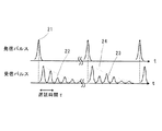
紙等のシート状媒体から反射された反射パルス15から各シート状媒体1の種別を検知する方法例について、図2を用いて説明する。或る時刻の発信パルス14が符号21のような時間波形であるとすると、複数枚重ねられたシート状媒体1の界面で反射されて、複数の反射エコーパルスが検出器8で受信される。シートの厚さがdであるとすると、そのシートの表側、裏側の界面で反射される電磁波は、光速cで空間を伝播するとして、
τ=2d/c (2)
で求まる時間τだけ時間差が生じる(実際にはシート状媒体の誘電率eに応じて√eだけ大きくなる)。シート状媒体1での吸収や反射損失があるために、図2のようにパルス強度が徐々に小さくなりながら、多層に重ねられた各シートからの反射を示す複数のパルス22、23が観測される。そして、パルスカウンティングにより、電磁波14を入射する面から何枚目のシート状媒体1の状態ないし性状の情報を見ているかが分かる。
An example of a method for detecting the type of each sheet-
τ = 2d / c (2)
The time difference is caused by the time τ determined by (actually increases by √e according to the dielectric constant e of the sheet-like medium). Due to absorption and reflection loss in the sheet-
この様なエコーパルスを観測するには、ピコ秒オーダーの高速パルスの場合には実時間観測は難しいので、サンプリング計測を行い、上に述べたように遅延時間を掃引しながら波形全体をトレースしてmsecオーダーで積層方向の各箇所の情報を得る。 In order to observe such an echo pulse, real-time observation is difficult for high-speed pulses of the order of picoseconds, so sampling measurement is performed, and the entire waveform is traced while sweeping the delay time as described above. To obtain information on each part in the stacking direction on the order of msec.
例えば、プリンタに印字媒体をセットする場合は、大抵は同種のものを用いることが多く、反射エコーパルスの大きさは、各印字媒体1での電磁波の吸収によって、図2の符号24で示すように単調に減少する。パルス間隔は印字媒体1の誘電率と厚さによって決まる。その減少の割合が、媒体材料の吸収係数αを含むexp(-αL)[Lは電磁波の伝播距離]で決まるのであれば、記憶部13に予めメモリしておいたデータとの比較で印字媒体を特定することができる。また、印字媒体1の厚さや誘電率εの大きさによって決まる1枚あたりの伝播遅延量τも、メモリデータと比較することで印字媒体の識別に用いられる。さらに、特定周波数に吸収があれば、パルス波形の変化として印字媒体1を識別することもできる。このように複数のパラメータを組み合わせて印字媒体の種別を検出するので、識別感度を向上させることができる。
For example, when a print medium is set in a printer, the same type is often used, and the magnitude of the reflected echo pulse is indicated by
例えば、再生紙とカラーコピー紙では、図3に示したように、1枚あたりの吸収率はほぼ同じであるが、伝播遅延は、普通紙各1枚0.16psec、カラーコピー紙各1枚0.19psecというように異なる。このことで再生紙とカラーコピー紙の識別をすることができる。吸収率や伝播遅延は、紙質(厚さ、密度、秤量、水分等)により異なるため、予めデータベース化しておけばよい。パラメータが多い場合には、予め手入力する手段と併用してもよい。 For example, as shown in FIG. 3, recycled paper and color copy paper have substantially the same absorption rate per sheet, but propagation delays are 0.16 psec per plain paper and 0.19 per color copy paper. psec is different. This makes it possible to distinguish between recycled paper and color copy paper. Since the absorption rate and propagation delay vary depending on the paper quality (thickness, density, weighing, moisture, etc.), it may be stored in a database in advance. When there are many parameters, it may be used together with a means for manually inputting in advance.
一方、セットした媒体中に異なる質のものが混在する場合には、例えば、図2の受信パルス22のようにパルス強度が極端に変化することでそれと識別でき、記憶部13中のメモリデータと比較して吸収係数から媒体1の種別を判別することもできる。すなわち、遅延量が異なればパルス位置の違いとして判別でき、パルス形状が違えばスペクトルの違いとして判別することができ、これらを併用してもよい。そして、各シート状媒体1の印字の際に、この種別の判別を基に、各シート状媒体1に対する印字動作条件の設定に関する信号を画像形成部2に出力する。
On the other hand, in the case where media of different quality are mixed in the set medium, for example, it can be distinguished from the fact that the pulse intensity changes extremely as in the received
読み取りに必要な電磁波パルス21の幅は、シート状媒体1の厚さにより決まるが、通常の紙であれば100μm前後であるため、(2)式を用いて1psecオーダーであることが分かる。
Although the width of the
次に、画像形成装置であるプリンタ装置の制御方式の一例について図4の流れ図を用いて説明する。印字命令が出されると(ステップ401)、本実施例の媒体情報センシング部5により、カセットに備えられた必要な印字媒体1の表面からの反射パルスのデータと記憶部13中のデータベースが逐次比較され各印字媒体の質が判別される(ステップ402)。この判別結果は、パルスカウントで何枚目の情報を見ているかをインクリメントしながら演算部12中のバッファメモリに格納される(ステップ403)。こうして、メモリには、印字前の印字媒体の情報が複数枚格納されるが、カセットから出力直前の印字媒体1の情報はメモリから画像形成部2に転送され、画像形成部2の画像形成条件(印加電圧、定着温度など)がこの印字媒体1に対して最適の条件に制御されて印字が実行される(ステップ404)。この後、残数が1枚以上ある場合には、何枚目が次にカセットから出力されるかをバッファメモリ及び反射パルス計測系にフィードバックして、適宜これらをリフレッシュする(ステップ405)。こうして、このループは、所望の印字プロセスが終了する(ステップ406)まで繰り返される。
Next, an example of a control method of the printer apparatus which is an image forming apparatus will be described with reference to the flowchart of FIG. When a print command is issued (step 401), the medium
この方式の制御では、カセットに格納されている印字媒体1の情報を表面から逐次取得できるので、印字制御(画像形成条件の設定)までの制御時間を長く取ることができる。従来の印字媒体検査装置では、一枚毎でしか計測できないために、印字直前に搬送系での印字媒体の計測が必要で、画像形成条件の設定の応答スピードを速くする必要がある。また、従来の印字媒体検査装置では、印字媒体からの透過電磁波を用いるので、印字媒体を挟んで装置を配する必要があり、装置の設置スペースについて制限も生じる。
In this type of control, the information of the
この様な短パルスを用いて電磁波送受信を行うには、図5のように光伝導素子41、44にパルスレーザを照射して発生する方法が好適に用いられる。光伝導素子41、44は次の様な構造を有する。この構造では、半絶縁性GaAs基板にMBEで250℃で低温成長したノンドープのLT-GaAsを1.5μm成長して、さらにその表面に、電磁波と空間との結合を高くするために、中心部に5μmのギャップを持つAuGe/Ni//Auからなるボータイアンテナ43、46が形成されている。反対側の表面には、集光効率を上げるためにSi半球レンズ42、45が接着されている。
In order to perform electromagnetic wave transmission / reception using such a short pulse, a method in which the
また、100フェムトから1ピコ秒程度のパルス幅を持つパルスレーザとしてモードロックレーザ40が用いられている。その出力が、ビームスプリッタ47で分岐されて、電源37でアンテナ43に30Vの電界を印加した発信器としての光伝導素子41に照射されると、数100フェムトから数ピコ秒のパルス幅を持つ電磁波パルスが発生する。これを軸外し放物面鏡49a、bでビーム調整して空間に放射させれば、印字媒体種別検査用の発信パルスとなる。このパルスはテラヘルツ領域のフーリエ周波数を含んだ広帯域電磁波となる。印字媒体からの反射パルスは、軸外し放物面鏡49c、dで集光されて同一構造の光伝導素子44で検出される。このとき、アンテナ46の両端に流れる電流を抵抗38の両端電圧の出力として取り出すが、同時に光が照射されて、光キャリアが発生しているタイミングでのみ電磁波パルスの電界の強さに応じた出力が得られる。従って、光行路を変動させる光遅延素子39が図1の遅延器10に相当し、反射ミラー48で遅延光パルスと電磁波パルスを同時に照射することで、光伝導素子44は図1の検出器8とミキサ11を合わせた機能を持つことになる。
A mode-locked
この様な装置を一体化して媒体情報センシング部5を構築することができる。パルスレーザとしてはチタンサファイア結晶や光ファイバを用いたモードロックレーザが安定しているが、より小型化するために過飽和吸収領域を持つ半導体モードロックレーザなどを用いてもよい。また、光伝送路として光ファイバを用いたり、光伝導素子と光導波路を同一基板上に集積化させることで、より小型で安定した装置とすることができる。
The medium
本実施例においては反射パルスを用いて信号検出するが、透過パルスを併用してもよい。その場合には、電磁波の発生器と他の検出器の間に印字媒体が配置されるようにする。ただし、反射波を用いる場合には複数毎重ねられたシートの各表面の状態を判別できるのに対して、透過波を用いる場合には検査する紙全体の平均を検知することになる。さらに、発生器と検出器の配置において、反射電磁波を利用するタイプでは、媒体の同一面側に置けるのでスペース利用効率が良く、プリンタ内部など高密度実装してある装置ではこの反射型が優れている。 In this embodiment, a signal is detected using a reflected pulse, but a transmitted pulse may be used in combination. In that case, the print medium is arranged between the electromagnetic wave generator and the other detector. However, when the reflected wave is used, the state of each surface of the stacked sheets can be determined, whereas when the transmitted wave is used, the average of the entire paper to be inspected is detected. Furthermore, in the arrangement of the generator and detector, the type that uses reflected electromagnetic waves can be placed on the same side of the medium, so that space utilization efficiency is good. Yes.
また、上記構成では、電磁波として連続的に出力されるパルスを用いているが、量子カスケードレーザや共鳴トンネルダイオード発生器のようにコヒーレンスの高い連続波を用いて反射電磁波との干渉で媒体の情報を取得することもできる。この場合の、検出原理は上述したとおりである。 In the above configuration, pulses that are continuously output as electromagnetic waves are used. However, information on the medium can be obtained by interference with reflected electromagnetic waves using continuous waves with high coherence, such as quantum cascade lasers and resonant tunnel diode generators. You can also get In this case, the detection principle is as described above.
以上の様な電磁波送受信部を含む媒体情報センシング部5を、複写機、インクジェットプリンタ、レーザビームプリンタなどにおける記録媒体をセットするカセットまたは搬送系に備えることで、操作者が手動で印字媒体の選択操作をすることなく自動的に印字動作条件を最適に設定ないし設定変更することができる。そのため、印字の失敗による時間や印字媒体の無駄などをなくすことができる。また、テラヘルツ領域の電磁波を使って媒体の検出を行うので、遮光などの必要がなくノイズに強い検出とできる。さらに、複数パラメータを用いて記録媒体の判別を行えるので、記録媒体の識別感度が向上するという特徴を有する。本実施例では、複数枚を同時にセンシングする方式を採っているが、勿論、1枚ずつセンシングを行う方式を用いてもよい。
By providing the medium
以上に述べたように、本実施例によれば、ミリ波からテラヘルツ領域の電磁波を用いて、積層されたシート状に重ねられた印字媒体の種別を検査することで、高速に精度の高い最適印字制御を行うことができる。このため、時間や印字媒体の無駄を省いて経済性の向上に結び付けることができる。また、光よりも波長の長い電磁波を用いて、より識別感度を向上させられ、複数枚の印字媒体を一括して識別できる。 As described above, according to the present embodiment, by using the electromagnetic waves in the millimeter wave to terahertz region, the type of the print medium stacked in the laminated sheet shape is inspected, and the optimum is achieved with high accuracy at high speed. Printing control can be performed. For this reason, it is possible to save time and waste of the printing medium and to improve the economy. Further, the identification sensitivity can be further improved by using an electromagnetic wave having a wavelength longer than that of light, and a plurality of print media can be collectively identified.
(実施例2)
次に、本発明の実施例2について図6を用いて説明する。実施例2では、電磁波パルスによる媒体情報センシング部として図6のような集積モジュールを用いる。
(Example 2)
Next,
この集積モジュールでは、基板50上には半導体モードロックレーザ60が実装され、約0.3psecのパルスが発生されて光導波路61に結合する。伝播したレーザ光の一方はテラヘルツ発生器65に照射され、0.5psec程度のパルス幅をもつ電磁波66に変換されて伝送路57a、bを伝播する。光導波路61で分岐されたもう一方のレーザ光は、光遅延器62を介して符号64の光路を伝播して検出器63に照射される。
In this integrated module, a semiconductor mode-locked laser 60 is mounted on the substrate 50 and a pulse of about 0.3 psec is generated and coupled to the optical waveguide 61. One of the propagated laser beams is irradiated to the terahertz generator 65, converted into an electromagnetic wave 66 having a pulse width of about 0.5 psec, and propagates through the
ここで、このモジュールの構成について示す。半絶縁性のGaAs基板50の上に、光感光性を持つ絶縁性樹脂52が形成され、Y分岐光導波路61は、樹脂52の一部の領域のみホトリソグラフィ工程により屈折率が周囲よりも高くなっている。この樹脂として、例えば、感光性ポリシラン[商品名:グラシア(日本ペイント製)]が好適に用いられる。これ以外にも、BCB、ポリイミドなどの光学樹脂で感光性のあるものが、光導波路兼電気的絶縁層として適している。テラヘルツ発生器65は低温成長で形成したアンドープのLT-GaAsに電極を形成した光伝導スイッチ素子である。伝送路を兼ねた電極57a、bの両端に電圧56を印加して、波長800nm程度のレーザパルス光が照射されると、電磁波パルスが発生する。
Here, the configuration of this module will be described. An insulating resin 52 having photosensitivity is formed on a semi-insulating GaAs substrate 50, and the Y-branch optical waveguide 61 has a refractive index higher than that of the surroundings by a photolithography process only in a part of the resin 52. It has become. As this resin, for example, photosensitive polysilane [trade name: Gracia (made by Nippon Paint)] is preferably used. In addition, optical resins such as BCB and polyimide that are photosensitive are suitable as an optical waveguide / electrical insulating layer. The terahertz generator 65 is a photoconductive switch element in which an electrode is formed on undoped LT-GaAs formed by low temperature growth. When a voltage 56 is applied to both ends of the
光検出器63は、テラヘルツ発生器と同様の構造の光伝導スイッチ素子であり、レーザパルス光が照射されたタイミングでのみフォトキャリアが発生し、伝送路を伝播してきた電磁波パルスの電界の大きさに応じて電流が流れて信号として検出できる。高周波パルス発生側のDC電圧を分離するために、光伝導スイッチは伝送路の片方の導体57bとは分離した形となっている。従って、遅延器62の遅延量を変化させることで、テラヘルツパルスの電界強度の時間変化を計測することができる。遅延器62は、不図示の遅延導波路と光スイッチや屈折率を変化させる素子などで構成できる。 The photodetector 63 is a photoconductive switch element having a structure similar to that of the terahertz generator, and photocarriers are generated only at the timing when the laser pulse light is irradiated, and the magnitude of the electric field of the electromagnetic wave pulse that has propagated through the transmission path. In response to this, a current flows and can be detected as a signal. In order to separate the DC voltage on the high frequency pulse generation side, the photoconductive switch is separated from one conductor 57b of the transmission line. Therefore, by changing the delay amount of the delay device 62, it is possible to measure the temporal change in the electric field strength of the terahertz pulse. The delay device 62 can be composed of a delay waveguide (not shown), an optical switch, an element that changes the refractive index, and the like.
本実施例でも、アンテナ51で空間に電磁波パルス53を放射させ、記録媒体からの反射電磁波54を上記実施例で説明した様に受信、処理して、非接触に記録媒体の状態を検出する。検出方法としては、本実施例のようなもの以外に、EO結晶を光検出器63の前に備えて、テラヘルツパルス強度の時間変動をEO結晶のポッケルス効果の変動にして、パルスレーザ60から分岐してきた光の透過光強度を光検出器で測定する方法でもよい。ビームを制御するために半球状のレンズ58をアンテナ51上に装着して狭放射角ビーム53にしたり、アンテナを可動性にしてビーム伝播方向をスキャンできるようにしてもよい。
Also in this embodiment, the electromagnetic wave pulse 53 is radiated to the space by the antenna 51, and the reflected electromagnetic wave 54 from the recording medium is received and processed as described in the above embodiment, thereby detecting the state of the recording medium in a non-contact manner. As a detection method, in addition to the method of the present embodiment, an EO crystal is provided in front of the photodetector 63, and the time variation of the terahertz pulse intensity is made a variation of the Pockels effect of the EO crystal to branch from the pulse laser 60. The transmitted light intensity of the transmitted light may be measured by a photodetector. In order to control the beam, a
この様な集積モジュールを用いることで装置全体の小型化、低価格化が可能となる。ここでは、1台のモードロックレーザを用いて短パルスを発生させる形態としたが、異なる発振波長を持つ2台のレーザダイオードのビート信号でテラヘルツ連続波を発生させる方式でもよい。 By using such an integrated module, the entire apparatus can be reduced in size and price. Here, the short pulse is generated by using one mode-locked laser, but a system in which a terahertz continuous wave is generated by beat signals of two laser diodes having different oscillation wavelengths may be used.
(実施例3)
本発明の実施例3はインクジェットプリンタに関わるものである。本実施例では、図7のように印字媒体74上のインク71の塗布状態(印字状態)76を検出するものである。媒体情報センシング部を印字ヘッド70内に組み込み配置した場合、発信された電磁波72に対して、印字後のインクの部分からの反射電磁波73の伝播状態が印字状態に応じて変化するが、これに関する情報をメモリ(記憶部)に格納しておいて印刷しながら同時にその印字状態を検出、判別できる。ここにおいて、印字ヘッド70は、プラテン75の伸長方向に沿って矢印の方向に往復走査され、印字媒体74は、これを挟んで、印字ヘッド70のある側とは反対側にあるプラテン75に支えられつつ矢印方向に間欠的に搬送される。こうして、印字媒体74上に、2次元的に印刷が施される。
(Example 3)
上記構成において、印字媒体74の吸湿状態や気温、湿度などの影響で、インクの乾燥度や媒体への染み込み具合が変化するが、これを、実施例1で説明したように電磁波の吸収、伝播遅延変化、パルス波形変化などとして検出して、検出結果をメモリデータと比較して印字状況を判別、把握する。この情報を基に、インクヘッド70の印字動作条件(ノズルからの吐出圧、温度、ノズルと印字媒体との距離など)を自動的に設定ないし設定変更することで、リアルタイムに最適な印字状態に制御しつつ印字を行うことができる。その他の点は、上記実施例と同様である。
In the above configuration, the degree of ink drying and the degree of penetration into the medium change under the influence of the moisture absorption state, temperature, humidity, etc. of the
ところで、記録媒体の複数の箇所に個別に電磁波を照射し、その反射波を検出することにより、より的確な記録媒体の状態を知ることができる。特に、すでに印字や画像が形成された記録媒体の状態を検出するときに有効である。つまり、トナーやインクの付着した部分の電磁波の伝播状態とトナーやインクの付着していない部分の電磁波の伝播状態とを的確に判別することにより、より精度の高い画像形成が可能になる。円状のスポットを紙に照射することにより、両者を検出することも可能であるが、トナーやインクのある部分とない部分の電磁波が混在してしまい、精度の良い信号分離が難しい場合がある。したがって、複数箇所に個別に照射することにより、個別の情報を的確に得られるという利点がある。 By the way, it is possible to know the state of the recording medium more accurately by individually irradiating a plurality of portions of the recording medium with electromagnetic waves and detecting the reflected waves. This is particularly effective when detecting the state of a recording medium on which a print or image has already been formed. That is, it is possible to form an image with higher accuracy by accurately discriminating between the propagation state of the electromagnetic wave in the portion where the toner or ink is adhered and the propagation state of the electromagnetic wave in the portion where the toner or ink is not adhered. It is possible to detect both by irradiating the paper with a circular spot. However, there may be a case where the electromagnetic wave of the part where toner or ink is present and the part where the toner or ink is not present are mixed, and accurate signal separation may be difficult. . Therefore, there is an advantage that individual information can be accurately obtained by individually irradiating a plurality of locations.
さらに、複数回の電磁波を照射することや異なる周波数帯域の電磁波を照射することも可能であり、上述の方法と併用してもよい。 Furthermore, it is possible to irradiate electromagnetic waves a plurality of times or to irradiate electromagnetic waves of different frequency bands, and may be used in combination with the above-described method.
格納手段としては、あらかじめデータベース化しておくことが好ましいが、複数の電磁波の照射により、一つの反射波のデータをデータベース化し、他の反射波のデータと比較することにより、記録媒体の状態を判別することも可能である。 As a storage means, it is preferable to create a database in advance, but by reflecting a plurality of electromagnetic waves, one reflected wave data is made into a database and compared with other reflected wave data to determine the state of the recording medium. It is also possible to do.
1‥記録媒体(積層媒体)
2、12‥設定手段(演算器、画像形成部)
5‥媒体情報センシング部
6、7、40、41、43、51、60、65‥電磁波照射手段(電磁波発生器、光伝導素子、レーザ、アンテナ)
8、9、10、11、38、39、40、44、46、51、60、62、63‥検出手段(電磁波検出器、光伝導素子、遅延器、ミキサ、レーザ、アンテナ、抵抗)
12‥判別手段(演算器)
13‥格納手段(記憶部)
14、21、53、72‥発信電磁波(送信パルス)
15、22、23、54、73‥反射電磁波(受信パルス)
1. Recording media (laminated media)
2, 12 ... Setting means (calculator, image forming unit)
5. Medium
8, 9, 10, 11, 38, 39, 40, 44, 46, 51, 60, 62, 63 ... detection means (electromagnetic wave detector, photoconductive element, delay device, mixer, laser, antenna, resistance)
12. Determining means (calculator)
13. Storage means (storage unit)
14, 21, 53, 72 ... Transmitted electromagnetic waves (transmitted pulses)
15, 22, 23, 54, 73 ... Reflected electromagnetic wave (received pulse)
Claims (4)
積層された記録媒体で反射した前記電磁波を検出するための検出部と、
前記記録媒体の種別を検出するための情報を予め記憶するための記憶部と、
前記検出部を用いて得る前記反射した電磁波から得る信号をモニターして前記記録媒体の種別を検出するための情報を取得し、該取得した情報と前記記憶部が記憶する情報とを比較することにより、前記記録媒体の種別を検出するための演算部と、
を有し、
前記記録媒体の種別を検出するための情報は、前記信号が有しているパルスの強度が減少する割合およびパルスの伝播遅延量を含み、
前記演算部は、前記信号が有しているパルスを数えることにより、前記積層された記録媒体の厚さ方向に関する該記録媒体ごとの位置を取得し、前記信号が有しているパルスごとに前記記録媒体の種別を検出することを特徴とする画像形成装置。 A generator for generating an electromagnetic wave having a frequency in the terahertz region;
A detection unit for detecting the electromagnetic wave reflected by the laminated recording medium;
A storage unit for storing in advance information for detecting the type of the recording medium;
Monitoring a signal obtained from the reflected electromagnetic wave obtained using the detection unit to obtain information for detecting the type of the recording medium, and comparing the obtained information with information stored in the storage unit By means of this, an arithmetic unit for detecting the type of the recording medium ,
Have,
The information for detecting the type of recording medium is viewed including the propagation delay of the rate and pulse intensity of the pulse of the signal has to decrease,
The calculation unit obtains a position for each recording medium in the thickness direction of the stacked recording media by counting the pulses that the signal has, and for each pulse that the signal has, An image forming apparatus for detecting a type of a recording medium .
前記遅延部は、パルスレーザの光行路を変動させる光遅延素子を含むことを特徴とする請求項3に記載の画像形成装置。The image forming apparatus according to claim 3, wherein the delay unit includes an optical delay element that varies an optical path of a pulse laser.
Priority Applications (1)
| Application Number | Priority Date | Filing Date | Title |
|---|---|---|---|
| JP2005203439A JP4663433B2 (en) | 2005-07-12 | 2005-07-12 | Image forming apparatus |
Applications Claiming Priority (1)
| Application Number | Priority Date | Filing Date | Title |
|---|---|---|---|
| JP2005203439A JP4663433B2 (en) | 2005-07-12 | 2005-07-12 | Image forming apparatus |
Publications (3)
| Publication Number | Publication Date |
|---|---|
| JP2007021779A JP2007021779A (en) | 2007-02-01 |
| JP2007021779A5 JP2007021779A5 (en) | 2008-08-21 |
| JP4663433B2 true JP4663433B2 (en) | 2011-04-06 |
Family
ID=37783174
Family Applications (1)
| Application Number | Title | Priority Date | Filing Date |
|---|---|---|---|
| JP2005203439A Expired - Fee Related JP4663433B2 (en) | 2005-07-12 | 2005-07-12 | Image forming apparatus |
Country Status (1)
| Country | Link |
|---|---|
| JP (1) | JP4663433B2 (en) |
Families Citing this family (3)
| Publication number | Priority date | Publication date | Assignee | Title |
|---|---|---|---|---|
| JP4898553B2 (en) * | 2007-05-22 | 2012-03-14 | 株式会社リコー | Double feed detection device, image forming device |
| JP5084620B2 (en) | 2008-06-06 | 2012-11-28 | キヤノン株式会社 | Image reading apparatus and image forming apparatus having the same |
| JP2014122875A (en) | 2012-11-26 | 2014-07-03 | Canon Inc | Device and method for measuring layered object |
Citations (10)
| Publication number | Priority date | Publication date | Assignee | Title |
|---|---|---|---|---|
| JP2000171416A (en) * | 1998-12-03 | 2000-06-23 | Canon Inc | Medium data detecting apparatus, image forming apparatus, medium data detecting method, image forming method and storage medium |
| JP2000275167A (en) * | 1999-03-26 | 2000-10-06 | Sony Corp | Paper quality detector, printer and copier |
| JP2001013088A (en) * | 1999-07-01 | 2001-01-19 | Canon Inc | Apparatus and method for detecting quality of paper, image forming apparatus and image forming control means |
| JP2001290315A (en) * | 2000-04-05 | 2001-10-19 | Minolta Co Ltd | Image forming device |
| JP2002103566A (en) * | 2000-09-28 | 2002-04-09 | Ricoh Co Ltd | Method and apparatus for controlling ink layer thickness, printer using the same apparatus as well as ink used for the apparatus |
| JP2004026486A (en) * | 2001-08-21 | 2004-01-29 | Canon Inc | Signal output device, sheet material type distinguishing device, image formation device, sheet material type distinguishing method, and information output device |
| JP2005078464A (en) * | 2003-09-02 | 2005-03-24 | Canon Inc | Object information sensing device and image reader |
| JP2005098744A (en) * | 2003-09-22 | 2005-04-14 | Seiko Epson Corp | Material quality detection method and device |
| JP2005157601A (en) * | 2003-11-25 | 2005-06-16 | Canon Inc | Layered object counting device and method using electromagnetic wave |
| JP2005535875A (en) * | 2002-08-08 | 2005-11-24 | メッツォ ペーパー カルルスタッド アクチボラグ | Measurement configuration at a shortened dry end of a tissue machine |
-
2005
- 2005-07-12 JP JP2005203439A patent/JP4663433B2/en not_active Expired - Fee Related
Patent Citations (10)
| Publication number | Priority date | Publication date | Assignee | Title |
|---|---|---|---|---|
| JP2000171416A (en) * | 1998-12-03 | 2000-06-23 | Canon Inc | Medium data detecting apparatus, image forming apparatus, medium data detecting method, image forming method and storage medium |
| JP2000275167A (en) * | 1999-03-26 | 2000-10-06 | Sony Corp | Paper quality detector, printer and copier |
| JP2001013088A (en) * | 1999-07-01 | 2001-01-19 | Canon Inc | Apparatus and method for detecting quality of paper, image forming apparatus and image forming control means |
| JP2001290315A (en) * | 2000-04-05 | 2001-10-19 | Minolta Co Ltd | Image forming device |
| JP2002103566A (en) * | 2000-09-28 | 2002-04-09 | Ricoh Co Ltd | Method and apparatus for controlling ink layer thickness, printer using the same apparatus as well as ink used for the apparatus |
| JP2004026486A (en) * | 2001-08-21 | 2004-01-29 | Canon Inc | Signal output device, sheet material type distinguishing device, image formation device, sheet material type distinguishing method, and information output device |
| JP2005535875A (en) * | 2002-08-08 | 2005-11-24 | メッツォ ペーパー カルルスタッド アクチボラグ | Measurement configuration at a shortened dry end of a tissue machine |
| JP2005078464A (en) * | 2003-09-02 | 2005-03-24 | Canon Inc | Object information sensing device and image reader |
| JP2005098744A (en) * | 2003-09-22 | 2005-04-14 | Seiko Epson Corp | Material quality detection method and device |
| JP2005157601A (en) * | 2003-11-25 | 2005-06-16 | Canon Inc | Layered object counting device and method using electromagnetic wave |
Also Published As
| Publication number | Publication date |
|---|---|
| JP2007021779A (en) | 2007-02-01 |
Similar Documents
| Publication | Publication Date | Title |
|---|---|---|
| US7688078B2 (en) | System and method for counting number of layers of multilayer object by means of electromagnetic wave | |
| CA2930466C (en) | System for determining at least one property of a sheet dielectric sample using terahertz radiation | |
| EP1864111B1 (en) | Inspection apparatus using terahertz waves | |
| JP3950820B2 (en) | High frequency electric signal control device and sensing system | |
| CN107148568B (en) | Inspection apparatus using THz frequency band | |
| EP0577285A1 (en) | Surface plasmon resonance measuring instruments | |
| EP1774288A1 (en) | Sensing apparatus | |
| NL8401328A (en) | MICROWAVE MOISTURE SENSOR. | |
| JP4663433B2 (en) | Image forming apparatus | |
| JP4508578B2 (en) | Image information acquisition apparatus and image forming apparatus | |
| JP6697130B2 (en) | Terahertz transceiver | |
| JP5570771B2 (en) | Authenticity discrimination method and apparatus for paper sheets using terahertz light | |
| KR100817615B1 (en) | Laser-induced ultrasonic apparatus for measuring defects of substance and the implemented method thereof | |
| JP4939139B2 (en) | Image forming apparatus and image forming method for forming image on sheet-like medium | |
| US8144370B2 (en) | Image forming apparatus, printing method and printing apparatus | |
| JP2008157633A (en) | Electromagnetic wave detector and electromagnetic wave detection system | |
| US7608827B2 (en) | Near-field terahertz imaging | |
| JP2002257932A (en) | Imaging device of type detecting reflected electromagnetic wave | |
| JP2007178284A (en) | Detection device for detecting object buried in planar object | |
| JP4953984B2 (en) | Image forming apparatus, printing method, and printing apparatus | |
| Oyama et al. | Inspection apparatus using TH z BAND | |
| KR20220034494A (en) | Probe for detecting near field and near field detecting system including the same | |
| Kitagishi et al. | Development of a high-speed spectroscopic imaging system over a wide frequency range with THz-TDS | |
| JP2009023782A (en) | Sheet conveying device and image forming device |
Legal Events
| Date | Code | Title | Description |
|---|---|---|---|
| A521 | Written amendment |
Free format text: JAPANESE INTERMEDIATE CODE: A523 Effective date: 20080703 |
|
| A621 | Written request for application examination |
Free format text: JAPANESE INTERMEDIATE CODE: A621 Effective date: 20080703 |
|
| A131 | Notification of reasons for refusal |
Free format text: JAPANESE INTERMEDIATE CODE: A131 Effective date: 20100707 |
|
| A521 | Written amendment |
Free format text: JAPANESE INTERMEDIATE CODE: A523 Effective date: 20100902 |
|
| A131 | Notification of reasons for refusal |
Free format text: JAPANESE INTERMEDIATE CODE: A131 Effective date: 20101012 |
|
| A521 | Written amendment |
Free format text: JAPANESE INTERMEDIATE CODE: A523 Effective date: 20101210 |
|
| TRDD | Decision of grant or rejection written | ||
| A01 | Written decision to grant a patent or to grant a registration (utility model) |
Free format text: JAPANESE INTERMEDIATE CODE: A01 Effective date: 20101228 |
|
| A01 | Written decision to grant a patent or to grant a registration (utility model) |
Free format text: JAPANESE INTERMEDIATE CODE: A01 |
|
| A61 | First payment of annual fees (during grant procedure) |
Free format text: JAPANESE INTERMEDIATE CODE: A61 Effective date: 20110105 |
|
| R150 | Certificate of patent or registration of utility model |
Free format text: JAPANESE INTERMEDIATE CODE: R150 |
|
| FPAY | Renewal fee payment (event date is renewal date of database) |
Free format text: PAYMENT UNTIL: 20140114 Year of fee payment: 3 |
|
| LAPS | Cancellation because of no payment of annual fees |