JP4661269B2 - Imaging apparatus and program - Google Patents
Imaging apparatus and program Download PDFInfo
- Publication number
- JP4661269B2 JP4661269B2 JP2005056081A JP2005056081A JP4661269B2 JP 4661269 B2 JP4661269 B2 JP 4661269B2 JP 2005056081 A JP2005056081 A JP 2005056081A JP 2005056081 A JP2005056081 A JP 2005056081A JP 4661269 B2 JP4661269 B2 JP 4661269B2
- Authority
- JP
- Japan
- Prior art keywords
- focusing
- subject
- setting
- focus
- obstacle
- Prior art date
- Legal status (The legal status is an assumption and is not a legal conclusion. Google has not performed a legal analysis and makes no representation as to the accuracy of the status listed.)
- Expired - Fee Related
Links
Images


Description
本発明は、被写体に焦点を合わせる機能を備えた撮影装置及びプログラムに関する。 The present invention relates to a photographing apparatus and a program having a function of focusing on a subject.
従来、オートフォーカスカメラにおいて、ユーザが望む被写体位置に焦点を合わせる方法として、フォーカスエリアを狭くするピンポイントAF(Auto Focus)や、複数のフォーカスエリアの中から適当と思われる位置に焦点を合わせるマルチポイントAF等がある。このような方法により、被写体の特定の部分に焦点を合わせたり、被写体のない中央部に焦点が合ってしまう、いわゆる中抜け画像を防いだりすることができる。また、被写体までの距離を測定する測距装置において、複数のIREDを用いることにより、スポット外れや中抜けを防止し、測距精度を向上させる技術が開示されている(例えば、特許文献1参照。)。
しかし、被写体と撮影装置との間に障害物が存在する場合、例えば、動物園で檻の中の動物を撮影する場合や、ネット越しに被写体を撮影する場合には、檻やネットに焦点が合ってしまうため、被写体に焦点を合わせて撮影することが困難であった。 However, when there is an obstacle between the subject and the imaging device, for example, when shooting an animal in a cage in a zoo or when shooting a subject over the net, the kite and the net are in focus. Therefore, it is difficult to shoot with the subject focused.
本発明は、上記の従来技術における問題に鑑みてなされたものであって、被写体と撮影装置との間に障害物が存在する場合に、被写体に焦点を合わせて撮影することができる撮影装置及びプログラムを提供することを課題とする。 The present invention has been made in view of the above-described problems in the prior art, and in the case where an obstacle exists between the subject and the photographing device, the photographing device capable of photographing with the subject in focus and The challenge is to provide a program.
上記課題を解決するため、請求項1に記載の発明は、焦点を合わせる合焦手段を備えた撮影装置において、被写体と前記撮影装置との間に存在し、且つ当該撮影装置の光軸方向において前記被写体の一部と重なる障害物を非合焦対象として設定する第1の設定手段と、前記被写体を合焦対象として設定する第2の設定手段と、前記第1の設定手段により設定された非合焦対象に焦点を合わせないように前記合焦手段を制御する第1の合焦制御手段と、前記第2の設定手段により設定された合焦対象に焦点を合わせるように前記合焦手段を制御する第2の合焦制御手段と、を備え、前記第2の設定手段は、前記第1の設定手段により設定された障害物の位置から後方へ隔てた距離を指定する指定手段を含み、当該指定手段により指定された距離に位置する被写体を合焦対象として設定することを特徴とする。
請求項2に記載の発明は、焦点を合わせる合焦手段を備えた撮影装置において、被写体と前記撮影装置との間に存在し、且つ当該撮影装置の光軸方向において前記被写体の一部と重なる障害物を非合焦対象として設定する第1の設定手段と、前記第1の設定手段により設定された障害物の周辺において、当該障害物の焦点距離と異なる焦点距離に位置する被写体を探索して、当該被写体を合焦対象として設定する第2の設定手段と、前記第1の設定手段により設定された非合焦対象に焦点を合わせないように前記合焦手段を制御する第1の合焦制御手段と、前記第2の設定手段により設定された合焦対象に焦点を合わせるように前記合焦手段を制御する第2の合焦制御手段と、を備えたことを特徴とする。
請求項3に記載の発明は、焦点を合わせる合焦手段を備えた撮影装置において、被写体と前記撮影装置との間に存在し、且つ当該撮影装置の光軸方向において前記被写体の一部と重なる障害物を非合焦対象として設定する第1の設定手段と、前記被写体を合焦対象として設定する第2の設定手段と、前記第1の設定手段により設定された非合焦対象に焦点を合わせないように前記合焦手段を制御する第1の合焦制御手段と、前記第2の設定手段により設定された合焦対象に焦点を合わせるように前記合焦手段を制御する第2の合焦制御手段と、前記被写体及び前記障害物を含む画像の画像データを取得する撮影手段と、前記撮影手段により取得された画像データに基づいて、複数の異なる位置で、前記障害物の領域の一部をポイント指定するための第1の指定手段と、を備え、前記第1の設定手段は、前記第1の指定手段によりポイント指定された一部領域に基づいて前記障害物を前記非合焦対象として設定するものであり、前記第1の指定手段によりポイント指定された複数位置の一部領域での焦点距離が一定でない場合には、ポイント指定をやり直させることを特徴とする。
In order to solve the above-described problem, the invention according to
According to a second aspect of the present invention, there is provided a photographing apparatus provided with a focusing means for focusing, which exists between the subject and the photographing apparatus and overlaps a part of the subject in the optical axis direction of the photographing apparatus. A first setting unit that sets an obstacle as an out-of-focus object; and an object located at a focal length different from the focal length of the obstacle around the obstacle set by the first setting unit. A second setting unit that sets the subject as a focusing target, and a first focusing unit that controls the focusing unit so as not to focus on the non-focusing target set by the first setting unit. It is characterized by comprising: a focus control means; and a second focus control means for controlling the focus means so as to focus on the focus target set by the second setting means.
According to a third aspect of the present invention, there is provided a photographing device including a focusing unit for focusing, the photographing device is located between the subject and the photographing device, and overlaps a part of the subject in the optical axis direction of the photographing device. A first setting unit that sets an obstacle as a non-focus target, a second setting unit that sets the subject as a focus target, and a focus on the non-focus target set by the first setting unit. A first focusing control unit that controls the focusing unit so as not to match, and a second focusing unit that controls the focusing unit so as to focus on the focusing target set by the second setting unit. A focus control unit, an imaging unit that acquires image data of an image including the subject and the obstacle, and one of the obstacle regions at a plurality of different positions based on the image data acquired by the imaging unit. Specify the point First setting means for setting the obstacle as the out-of-focus object based on the partial area point-specified by the first specifying means. In the case where focal lengths in partial areas at a plurality of positions designated by the first designation means are not constant, point designation is performed again.
請求項4に記載の発明は、焦点を合わせる合焦手段を備えた撮影装置において、被写体と前記撮影装置との間に存在し、且つ当該撮影装置の光軸方向において前記被写体の一部と重なる障害物を非合焦対象として設定する第1の設定手段と、前記被写体を合焦対象として設定する第2の設定手段と、前記第1の設定手段により設定された非合焦対象に焦点を合わせないように前記合焦手段を制御する第1の合焦制御手段と、前記第2の設定手段により設定された合焦対象に焦点を合わせるように前記合焦手段を制御する第2の合焦制御手段と、前記被写体及び前記障害物を含む画像の画像データを取得する撮影手段と、前記撮影手段により取得された画像データに基づいて、前記障害物の領域の一部をポイント指定するための第1の指定手段と、前記撮影手段により取得された画像データに基づいて、前記被写体の領域の一部をポイント指定するための第2の指定手段と、を備え、前記第1の設定手段は、前記第1の指定手段によりポイント指定された一部領域に基づいて前記障害物を前記非合焦対象として設定し、前記第2の設定手段は、前記第2の指定手段によりポイント指定された一部領域に基づいて前記被写体を前記合焦対象として設定し、前記第1の設定手段及び前記第2の設定手段は、前記第1の指定手段によりポイント指定された一部領域のコントラスト値が、前記第2の指定手段によりポイント指定された一部領域のコントラスト値以上の場合には、ポイント指定をやり直させることを特徴とする。
請求項5に記載の発明は、焦点を合わせる合焦手段を備えた撮影装置において、被写体と前記撮影装置との間に存在し、且つ当該撮影装置の光軸方向において前記被写体の一部と重なる障害物を非合焦対象として設定する第1の設定手段と、前記被写体を合焦対象として設定する第2の設定手段と、前記第1の設定手段により設定された非合焦対象に焦点を合わせないように前記合焦手段を制御する第1の合焦制御手段と、前記第2の設定手段により設定された合焦対象に焦点を合わせるように前記合焦手段を制御する第2の合焦制御手段と、前記被写体及び前記障害物を含む画像の画像データを取得する撮影手段と、前記撮影手段により取得された画像データに基づいて、前記障害物の領域の一部をポイント指定するための第1の指定手段と、前記撮影手段により取得された画像データに基づいて、前記被写体の領域の一部をポイント指定するための第2の指定手段と、前記画像データ及び前記ポイント指定された一部領域を表示手段に表示させる表示制御手段と、を備え、前記第1の設定手段は、前記第1の指定手段によりポイント指定された一部領域に基づいて前記障害物を前記非合焦対象として設定し、前記第2の設定手段は、前記第2の指定手段によりポイント指定された一部領域に基づいて前記被写体を前記合焦対象として設定し、前記第1の指定手段及び前記第2の指定手段は、前記表示手段に表示されている画像上においてポイント指定し、前記表示制御手段は、前記第1の指定手段及び前記第2の指定手段によりポイント指定された位置同士の間隔が規定値以下であった場合には、ポイント指定される一部領域の大きさを小さくするか、又は、表示画像を拡大することを特徴とする。
請求項6に記載の発明は、焦点を合わせる合焦手段を備えた撮影装置のコンピュータを、被写体と前記撮影装置との間に存在し、且つ当該撮影装置の光軸方向において前記被写体の一部と重なる障害物を非合焦対象として設定する第1の設定手段、前記第1の設定手段により設定された障害物の周辺において、当該障害物の焦点距離と異なる焦点距離に位置する被写体を探索して、当該被写体を合焦対象として設定する第2の設定手段、前記第1の設定手段により設定された非合焦対象に焦点を合わせないように前記合焦手段を制御する第1の合焦制御手段、前記第2の設定手段により設定された合焦対象に焦点を合わせるように前記合焦手段を制御する第2の合焦制御手段、として機能させるためのプログラムである。
According to a fourth aspect of the present invention, there is provided a photographing apparatus provided with a focusing means for focusing, which exists between the subject and the photographing apparatus and overlaps a part of the subject in the optical axis direction of the photographing apparatus. A first setting unit that sets an obstacle as a non-focus target, a second setting unit that sets the subject as a focus target, and a focus on the non-focus target set by the first setting unit. A first focusing control unit that controls the focusing unit so as not to match, and a second focusing unit that controls the focusing unit so as to focus on the focusing target set by the second setting unit. Focus control means, photographing means for obtaining image data of an image including the subject and the obstacle, and point designation of a part of the obstacle area based on the image data obtained by the photographing means First designation means And a second designating unit for designating a part of the area of the subject based on the image data acquired by the imaging unit, wherein the first setting unit comprises the first designating unit. The obstacle is set as the out-of-focus target based on the partial area designated by the means, and the second setting means is based on the partial area designated by the second designation means. The subject is set as the in-focus object, and the first setting means and the second setting means are configured such that the contrast value of the partial area point-designated by the first designation means is the second designation. If the contrast value of the partial area designated by the means is greater than or equal to the contrast value, the point designation is performed again.
According to a fifth aspect of the present invention, there is provided a photographing device including a focusing unit for focusing, the photographing device is located between the subject and the photographing device, and overlaps a part of the subject in the optical axis direction of the photographing device. A first setting unit that sets an obstacle as a non-focus target, a second setting unit that sets the subject as a focus target, and a focus on the non-focus target set by the first setting unit. A first focusing control unit that controls the focusing unit so as not to match, and a second focusing unit that controls the focusing unit so as to focus on the focusing target set by the second setting unit. Focus control means, photographing means for obtaining image data of an image including the subject and the obstacle, and point designation of a part of the obstacle area based on the image data obtained by the photographing means First designation means A second specifying means for specifying a part of the area of the subject based on the image data acquired by the photographing means; and the display means for specifying the image data and the specified partial area of the point. Display control means for displaying, wherein the first setting means sets the obstacle as the out-of-focus object based on the partial area designated by the first designation means, and the first setting means 2 setting means sets the subject as the focus target based on the partial area designated by the second designation means, the first designation means and the second designation means, Point designation is made on the image displayed on the display means, and the display control means has an interval between positions designated by the first designation means and the second designation means equal to or less than a specified value. If there is, it reduces the size of the partial area to be point designation, or, characterized in that to enlarge the displayed image.
According to a sixth aspect of the present invention, there is provided a computer of a photographing apparatus provided with a focusing means for focusing, a part of the subject in the optical axis direction of the photographing apparatus that exists between the subject and the photographing apparatus. A first setting unit that sets an obstacle that overlaps with the obstacle as a non-focusing object, and searches for an object located at a focal length different from the focal length of the obstacle around the obstacle set by the first setting unit. Then, a second setting unit that sets the subject as a focusing target, and a first focusing unit that controls the focusing unit so as not to focus on the non-focusing target set by the first setting unit. A program for functioning as a focus control unit and a second focus control unit for controlling the focus unit so as to focus on the focus target set by the second setting unit.
本発明によれば、被写体と撮像装置との間に存在し、且つ撮影装置の光軸方向において被写体の一部と重なる障害物が存在する場合に、障害物と被写体とを識別して、障害物に焦点を合わせないようにするとともに、被写体に焦点を合わせて撮影することができる。 According to the present invention, when there is an obstacle that exists between the subject and the imaging device and overlaps with a part of the subject in the optical axis direction of the imaging device , the obstacle and the subject are identified and the obstacle is identified. In addition to avoiding focusing on an object, it is possible to shoot while focusing on a subject .
[第1の実施の形態]
以下、本発明の第1の実施の形態におけるデジタルカメラ10について詳細に説明する。
まず、構成を説明する。
図1は、デジタルカメラ10の機能的構成を示すブロック図である。図1に示すように、デジタルカメラ10は、CPU(Central Processing Unit)11、入力部12、RAM(Random Access Memory)13、伝送制御部14、表示部15、撮像部16、記録部17、記録媒体駆動部18等を備えて構成されており、各部はバス19により接続されている。
[First Embodiment]
Hereinafter, the
First, the configuration will be described.
FIG. 1 is a block diagram showing a functional configuration of the
CPU11は、記録部17に記憶されているシステムプログラムを読み出し、RAM13内に形成されたワークエリアに展開し、該システムプログラムに従って各部を制御する。また、CPU11は、記録部17に記憶されている各種処理プログラムを読み出してワークエリアに展開し、各種処理を実行する。
The
具体的に、CPU11は、入力部12を介してユーザにより指定された障害物領域の一部に基づいて障害物を認識する。ここで、障害物とは、被写体とデジタルカメラ10との間に存在し、且つ、デジタルカメラ10の光軸方向において被写体の一部と重なる位置に存在する物体をいい、例えば、動物園の動物を撮影する際の檻や、ネット越しに被写体を撮影する際のネット等をいう。また、CPU11は、入力部12を介してユーザにより指定された被写体領域の一部に基づいて、被写体を認識する。
Specifically, the
また、CPU11は、認識された被写体に焦点を合わせ、被写体を障害物とともに撮影するよう撮像部16を制御する。
Further, the
入力部12は、電源ボタン、撮影を指示するためのシャッターボタン、撮影に関する各種設定ボタン、決定ボタン及び方向指示ボタン等を備え、その各操作に応じた操作信号をCPU11に出力する。入力部12は、後述する第1の被写体撮影処理において、障害物を示す障害物領域の一部を指定するための第1の指定手段、及び被写体を示す被写体領域の一部を指定するための第2の指定手段としての機能を有する。
The
RAM13は、CPU11によって実行される各種プログラム及びこれらプログラムに係るデータを一時的に記憶するワークエリアを形成する。
The
伝送制御部14は、通信用ケーブル等により外部の電子機器、例えば、パーソナルコンピュータ等と接続され、画像データ等の送受信を制御する。なお、外部機器との接続は、赤外線や無線等の無線接続であってもよい。
The
表示部15は、LCD(Liquid Crystal Display)等のモニタにより構成され、CPU11から入力される表示信号の指示に従って、撮影しようとする画像及び撮影された画像等を表示画面上に表示する。
The
図2は、撮像部16の詳細構成を示す図である。撮像部16は、被写体を含む光学画像を電気信号に変換して画像データを取得する撮影手段としての機能を有する。ここで、図2を参照して撮像部16について説明する。
FIG. 2 is a diagram illustrating a detailed configuration of the
撮像レンズ21を通過した被写体像は、絞り機構22を介してCCD(Charge Coupled Device)23上に結像される。撮像レンズ21及び絞り機構22は、光学系駆動部24によって、焦点合わせのためにレンズ位置が移動され、また、適切な露出となるように絞り量が制御される。この撮像レンズ21の移動や絞り機構22の絞りは、測距センサや光量センサを含むセンサ部25によって検出された検出値がバス19を介してCPU11に出力され、CPU11で検出値に基づいて演算された撮像レンズ21の移動量や絞り機構22の絞り量を示す信号が光学系駆動部24に出力されることによって駆動がなされるものである。
The subject image that has passed through the
CCD23に被写体が結像されると、CCD23には入射光量に応じた電荷が蓄積され、この電荷は駆動回路26から与えられる駆動パルス信号によって順次読み出され、アナログ処理回路27に出力される。アナログ処理回路27では、色分離やゲイン調整、ホワイトバランス等の各種処理が行われ、処理された信号はA/D変換回路28を介してデジタル画像データ(以下、画像データという。)としてバッファレジスタ29に記憶される。
When the subject is imaged on the
バッファレジスタ29に記憶された画像データは、CPU11からの制御信号に基づいて、信号処理回路30において輝度信号及び色差信号に変換され、表示部15に表示される。また、信号処理回路30において処理された画像データは、CPU11からの制御信号に基づいて、圧縮伸張回路31において圧縮され、バス19を介して図1に示す記録部17又は記録媒体18aに記録される。
The image data stored in the
図1に戻り、記録部17は、フラッシュメモリ等の不揮発メモリ等により構成され、デジタルカメラ10に対応するシステムプログラム、及び該システムプログラム上で実行可能な各種処理プログラム、アプリケーションプログラム及びこれらのプログラムで処理されたデータ等を記録する。また、記録部17は、撮影された画像データを記録するための撮影画像記録領域171を有する。
Returning to FIG. 1, the
記録媒体駆動部18は、装着された記録媒体18aに対してデータを記録したり、既に記録されているデータを読み出して再生したりするための駆動回路である。装着される記録媒体18aとしては、スマートメディア(登録商標)、メモリースティック(登録商標)、コンパクトフラッシュ(登録商標)、SDカード、PCカード、ICカード、MO(magneto-optic)等の各種カードを用いることができ、これらの各種カードのいずれか又は複数のカードに応じた記録媒体駆動部18が設けられている。
The recording
次に、動作について説明する。
図3は、デジタルカメラ10のCPU11により実行される第1の被写体撮影処理を示すフローチャートである。当該処理は、CPU11と記録部17に記憶されている第1の被写体撮影処理プログラムとの協働によるソフトウエア処理により実現される処理である。
Next, the operation will be described.
FIG. 3 is a flowchart showing a first subject photographing process executed by the
まず、CCD23の初期化が行われる(ステップS1)。次に、表示部15に撮影条件選択画面が表示される(ステップS2)。図4に、表示部15に表示される撮影条件選択画面の例を示す。図4に示すように、「1.AUTO」、「2.シャッタースピード優先」、「3.露出優先」、「4.マクロ」、「5.景色」、「6.動物園」、「7.動物園手動」、「8.人物」、「9.終了」等の項目が表示される。ここで、ユーザは、入力部12を介して、いずれかの撮影条件を選択する。
First, the
次に、ユーザにより選択された撮影条件が動物園モードである場合には(ステップS3;YES)、焦点ポイント及び非焦点ポイントが設定される(ステップS4)。 Next, when the photographing condition selected by the user is the zoo mode (step S3; YES), the focal point and the non-focal point are set (step S4).
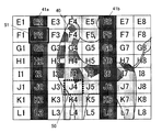
図5を参照して、ステップS4の焦点ポイント及び非焦点ポイントの設定方法について説明する。図5は、動物園にて檻の中の動物を撮影する際に表示部15に表示される表示画面の例である。被写体である動物40と、障害物である檻41a,41b,41c,41dとが表示されている。また、図5に示すA1,A2,A3,・・・は、CCD23の撮像面に配列されている複数の画素の位置を示すアドレスである。
With reference to FIG. 5, the setting method of the focus point and non-focus point of step S4 is demonstrated. FIG. 5 is an example of a display screen displayed on the
まず、ユーザは、表示部15に動物40及び檻41a,41b,41c,41dが表示された状態で、入力部12の方向指示ボタンを操作することにより焦点設定マーク50を上下左右に移動させる。そして、焦点設定マーク50が、焦点を合わせるべき動物40の表示領域の一部(例えば、図5のJ4)にある状態で決定ボタンを押下することにより焦点ポイントを設定する。焦点ポイントとして設定された部分が被写体であると認識される。
First, the user moves the
次に、入力部12の方向指示ボタンを操作することにより非焦点設定マーク51を上下左右に移動させ、非焦点設定マーク51が、焦点を合わせたくない檻41a,41b,41c,41dの表示領域の一部(例えば、図5のF2)にある状態で決定ボタンを押下することにより非焦点ポイントを設定する。同様に、非焦点設定マーク52を檻41a,41b,41c,41dの表示領域の一部(例えば、図5のN2)に移動させて非焦点ポイントを設定する。非焦点ポイントとして設定された部分が障害物であると認識される。
Next, the
図3に戻り、焦点ポイントとして設定された座標と非焦点ポイントとして設定された座標の座標間距離が規定値以下の場合には(ステップS5;YES)、図6に示すように、撮影時の表示画面が拡大表示され(ステップS6)、焦点ポイント及び非焦点ポイントが再設定される(ステップS4)。拡大表示させることにより、焦点ポイント及び非焦点ポイントの設定が容易になる。 Returning to FIG. 3, when the coordinate distance between the coordinates set as the focal point and the coordinates set as the non-focal point is equal to or less than the specified value (step S5; YES), as shown in FIG. The display screen is enlarged and displayed (step S6), and the focal point and the non-focus point are reset (step S4). By enlarging the display, it becomes easy to set the focal point and the non-focal point.
焦点ポイントとして設定された座標と非焦点ポイントとして設定された座標の座標間距離が規定値より大きい場合には(ステップS5;NO)、非焦点ポイントとして設定された部分(非焦点設定マーク51及び非焦点設定マーク52で設定された部分)の焦点距離が一定か否かが判断される(ステップS7)。非焦点ポイントとして設定された部分の焦点距離が一定でない場合には(ステップS7;NO)、ステップS4に戻り、焦点ポイント及び非焦点ポイントが再設定される。
If the coordinate distance between the coordinates set as the focal point and the coordinates set as the non-focal point is larger than the prescribed value (step S5; NO), the portion set as the non-focus point (the
非焦点ポイントとして設定された部分の焦点距離が一定である場合には(ステップS7;YES)、非焦点設定マーク51及び非焦点設定マーク52で設定された部分が同一の障害物を示していると判断され、非焦点ポイントに対する焦点距離より長い焦点距離においてのみ焦点を合わせるようにリミッタがかけられる(ステップS8)。そして、焦点ポイント及び非焦点ポイントに基づいてフォーカス制御が行われる(ステップS9)。ここで、撮像レンズ21を移動させながらCCD23が出力する画像信号の焦点ポイントのコントラストを検出し、そのコントラストが最大となる位置にレンズ位置が移動される。
When the focal length of the portion set as the non-focus point is constant (step S7; YES), the portions set by the
次に、焦点ポイントと非焦点ポイントにおけるコントラスト電圧値が比較される(ステップS10)。図7に、焦点ポイント(J4)におけるコントラスト電圧値と非焦点ポイント(F2)におけるコントラスト電圧値の例を示す。焦点ポイントにおけるコントラスト電圧値が非焦点ポイントにおけるコントラスト電圧値より大きい場合には(ステップS10;YES)、被写体に焦点が合っていると判断される(ステップS11)。そして、画像データが取り込まれ(ステップS12)、取り込まれたデータが記録部17の撮影画像記録領域171に格納される(ステップS13)。
Next, the contrast voltage values at the focal point and the non-focal point are compared (step S10). FIG. 7 shows an example of the contrast voltage value at the focal point (J4) and the contrast voltage value at the non-focal point (F2). When the contrast voltage value at the focal point is larger than the contrast voltage value at the non-focal point (step S10; YES), it is determined that the subject is in focus (step S11). Then, the image data is captured (step S12), and the captured data is stored in the captured
焦点ポイントにおけるコントラスト電圧値が非焦点ポイントにおけるコントラスト電圧値以下の場合には(ステップS10;NO)、ステップS4に戻り、焦点ポイント及び非焦点ポイントが再設定される。 When the contrast voltage value at the focus point is equal to or lower than the contrast voltage value at the non-focus point (step S10; NO), the process returns to step S4, and the focus point and the non-focus point are reset.
ステップS3において、選択された撮影条件が動物園モードでない場合には(ステップS3;NO)、選択されたモードの処理が行われる(ステップS14)。 In step S3, when the selected photographing condition is not the zoo mode (step S3; NO), the processing of the selected mode is performed (step S14).
ここで、動物園手動モードが選択された場合を例にして説明する。動物園手動モードが選択された場合には、まず、非焦点ポイントが設定される。非焦点ポイントの設定については、ステップS4における非焦点ポイントの設定と同様であるため、説明を省略する。 Here, a case where the zoo manual mode is selected will be described as an example. When the zoo manual mode is selected, first, a non-focus point is set. Since the setting of the non-focal point is the same as the setting of the non-focal point in step S4, description thereof is omitted.
非焦点ポイントの設定後、図8に示すように、非焦点ポイントの何cm後方に焦点を合わせるかを選択する画面が表示される。ユーザは、図8に示す焦点ポイント設定画面において、入力部12を介して、いずれかの距離を選択する。非焦点ポイントを基準にして、選択された距離だけ後方に焦点ポイントが設定される。
After setting the non-focus point, as shown in FIG. 8, a screen for selecting how many cm behind the non-focus point is to be focused is displayed. The user selects one of the distances via the
そして、焦点ポイントに焦点が合うように撮像レンズ21の位置が移動される。そして、画像データが取り込まれ、取り込まれたデータが記録部17の撮影画像記録領域171に格納される。
以上で、第1の被写体撮影処理が終了する。
Then, the position of the
This completes the first subject photographing process.
以上説明したように、第1の実施の形態におけるデジタルカメラ10によれば、障害物及び被写体を認識し、認識された被写体に焦点を合わせて撮影するので、被写体とデジタルカメラ10との間に障害物が存在する場合に、被写体に焦点を合わせて撮影することができる。
As described above, according to the
なお、図3に示す第1の被写体撮影処理のステップS6において、表示画面を拡大表示する代わりに、フォーカスポイントを小さくして、被写体に焦点を合わせることとしてもよい。図9(a)に示すように、檻41a,41b,41c,41dの間隔よりもフォーカスポイントPFが大きい場合には、動物40のみにフォーカスポイントPFを合わせることができない。そこで、図9(b)に示すように、フォーカスポイントPFを小さくして、動物40のみにフォーカスポイントPFを合わせることができるようにする。
In step S6 of the first subject photographing process shown in FIG. 3, instead of enlarging and displaying the display screen, the focus point may be reduced to focus on the subject. As shown in FIG. 9 (a), when the
[第2の実施の形態]
次に、本発明を適用した第2の実施の形態を詳細に説明する。
第2の実施の形態に示すデジタルカメラは、第1の実施の形態に示したデジタルカメラ10と同様の構成であるため、同一の構成部分については同一の符号を付し、その構成については説明を省略する。以下、第2の実施の形態に特徴的な構成及び処理について説明する。
[Second Embodiment]
Next, a second embodiment to which the present invention is applied will be described in detail.
Since the digital camera shown in the second embodiment has the same configuration as the
CPU11は、入力部12を介してユーザにより指定された障害物領域の一部に基づいて障害物を認識する。また、CPU11は、認識された障害物と焦点距離が異なる部分を被写体として認識する。
The
次に、動作について説明する。
図10は、第2の実施の形態のデジタルカメラのCPU11により実行される第2の被写体撮影処理を示すフローチャートである。当該処理は、CPU11と記録部17に記憶されている第2の被写体撮影処理プログラムとの協働によるソフトウエア処理により実現される処理である。
Next, the operation will be described.
FIG. 10 is a flowchart illustrating a second subject photographing process executed by the
まず、CCD23の初期化が行われる(ステップS21)。次に、表示部15に撮影条件選択画面が表示される(ステップS22)。第1の実施の形態と同様に、図4に示すような項目が表示される。ここで、ユーザは、入力部12を介して、いずれかの撮影条件を選択する。
First, the
次に、ユーザにより選択された撮影条件が動物園モードである場合には(ステップS23;YES)、表示部15の表示画面(ファインダ)に表示される障害物に非焦点設定マークを合わせてシャッターボタンを半押しするよう指示される。そして、非焦点設定マークが、焦点を合わせたくない障害物の表示領域の一部にある状態でシャッターボタンが半押しされると(ステップS24;YES)、障害物の表示領域内に非焦点ポイントが設定される(ステップS25)。そして、非焦点ポイントとして設定された部分が障害物であると認識される。ここで設定された非焦点ポイントが基準点となり、基準点に対する焦点距離が測定され、記録部17に記憶される(ステップS26)。
Next, when the photographing condition selected by the user is the zoo mode (step S23; YES), the shutter button is set with the non-focus setting mark on the obstacle displayed on the display screen (finder) of the
次に、CCD23の撮像面において基準点の周りを画素1つ分だけ移動した位置が比較点として設定される(ステップS27)。図11に示すように、F6が基準点(非焦点ポイント)として設定された場合、隣の画素であるF5が比較点となる。そして、比較点に対する焦点距離が測定される(ステップS28)。
Next, a position moved by one pixel around the reference point on the imaging surface of the
次に、基準点に対する焦点距離と比較点に対する焦点距離とが比較され、基準点に対する焦点距離と比較点に対する焦点距離とが同じ場合には(ステップS29;YES)、比較点も障害物を示していると判断され、ステップS27に戻る。そして、図11に示すように、さらに隣の画素であるF4が比較点として設定される。 Next, the focal length with respect to the reference point is compared with the focal length with respect to the comparison point. If the focal length with respect to the reference point and the focal length with respect to the comparison point are the same (step S29; YES), the comparison point also indicates an obstacle. It returns to step S27. Then, as shown in FIG. 11, the adjacent pixel F4 is set as a comparison point.
なお、比較点は予め定められたルールに従って移動させればよい。例えば、図11において、まず、基準点F6から1つ左の画素F5が比較点に設定され、基準点に対する焦点距離と比較点に対する焦点距離とが同じ場合には、さらに1つ左の画素F4が比較点に設定される。そして、基準点に対する焦点距離と新たな比較点に対する焦点距離とが同じ場合には、画素F4の1つ下の画素G4が比較点に設定される。同様に、H4、H5、H6、H7、H8、G8、F8、F7というように、比較点を移動させながら基準点に対する焦点距離と比較点に対する焦点距離とが比較される。 The comparison point may be moved according to a predetermined rule. For example, in FIG. 11, first, the pixel F5 that is one left from the reference point F6 is set as the comparison point, and when the focal length with respect to the reference point is the same as the focal length with respect to the comparison point, the pixel F4 that is one more left Is set as the comparison point. When the focal length with respect to the reference point is the same as the focal length with respect to the new comparison point, the pixel G4 immediately below the pixel F4 is set as the comparison point. Similarly, the focal length with respect to the reference point and the focal length with respect to the comparison point are compared while moving the comparison point, such as H4, H5, H6, H7, H8, G8, F8, and F7.
そして、基準点に対する焦点距離と比較点に対する焦点距離とが異なる場合には(ステップS29;NO)、比較点は障害物とは異なる部分、すなわち被写体を示していると認識され、比較点の位置(被写体)に焦点が合わせられる(ステップS30)。そして、画像データが取り込まれ(ステップS31)、取り込まれたデータが記録部17の撮影画像記録領域171に格納される(ステップS32)。
If the focal length with respect to the reference point is different from the focal length with respect to the comparison point (step S29; NO), the comparison point is recognized as indicating a portion different from the obstacle, that is, the subject, and the position of the comparison point. The subject is focused (step S30). Then, image data is captured (step S31), and the captured data is stored in the captured
ステップS23において、選択された撮影条件が動物園モードでない場合には(ステップS23;NO)、選択されたモードの処理が行われる(ステップS33)。
以上で、第2の被写体撮影処理が終了する。
In step S23, when the selected photographing condition is not the zoo mode (step S23; NO), the processing of the selected mode is performed (step S33).
Thus, the second subject shooting process is completed.
以上説明したように、第2の実施の形態におけるデジタルカメラによれば、障害物及び被写体を認識し、認識された被写体に焦点を合わせて撮影するので、被写体とデジタルカメラとの間に障害物が存在する場合に、被写体に焦点を合わせて撮影することができる。障害物を示す基準点の周りを画素1つ分ずつ移動させて、障害物と焦点距離が異なる部分を被写体として認識するので、あらゆる形状の障害物に対応することができる。 As described above, according to the digital camera in the second embodiment, the obstacle and the subject are recognized and the focused subject is photographed so that the obstacle is placed between the subject and the digital camera. Can be photographed while focusing on the subject. By moving around the reference point indicating the obstacle by one pixel at a time and recognizing a portion having a focal length different from that of the obstacle as the subject, it is possible to deal with obstacles of all shapes.
なお、上記各実施の形態における記述は、本発明に係る撮影装置の例であり、これに限定されるものではない。撮影装置を構成する各部の細部構成及び細部動作に関しても本発明の趣旨を逸脱することのない範囲で適宜変更可能である。 Note that the description in each of the above embodiments is an example of a photographing apparatus according to the present invention, and the present invention is not limited to this. The detailed configuration and detailed operation of each part of the photographing apparatus can be changed as appropriate without departing from the spirit of the present invention.
例えば、図12に示すように、被写体60と撮影装置との間に金網61が存在する場合、多点フォーカス70,71,72,73,74にて何か所か同じ焦点距離で焦点が合い、同じパターンが連続すると判断された場合に、金網であると認識することとしてもよい。そして、金網に対する焦点距離より長い焦点距離においてのみ焦点を合わせるようにレンズを駆動する。金網のパターンは画像データを2値化し、エッジを検出することにより求めればよい。
For example, as shown in FIG. 12, when a
また、檻等の障害物をセンサで自動認識して被写体に焦点を合わせることとしてもよい。この場合、赤外線やLED(Light Emitting Diode)等の光を被写体及び障害物に照射し、反射された光を検出することにより距離を測定し、その距離の差に基づいて、遠い方を被写体と判断して焦点を合わせる。遠近2つのセンサを設けて、遠方(被写体)用のセンサは照射位置を移動できるようにしておけば所定の範囲の距離を測定することができる。 Further, an obstacle such as a bag may be automatically recognized by a sensor to focus on the subject. In this case, the object and the obstacle are irradiated with light such as infrared rays or LEDs (Light Emitting Diodes), the distance is measured by detecting the reflected light, and the far side is determined as the subject based on the difference in the distance. Judge and focus. If two far and near sensors are provided, and the far (subject) sensor can move the irradiation position, a distance within a predetermined range can be measured.
また、被写体が動く場合には、被写体に対する焦点距離及び障害物に対する焦点距離を予めメモリに記憶させておき、シャッターボタンが押下される際に、焦点距離が、予め記憶されている被写体に対する焦点距離とほぼ一致した場合に画像データを取り込むようにする。一方、焦点距離が、予め記憶されている障害物に対する焦点距離とほぼ一致した場合には、撮影を行えないようにする。 In addition, when the subject moves, the focal length with respect to the subject and the focal length with respect to the obstacle are stored in advance in the memory, and when the shutter button is pressed, the focal length is stored in advance with respect to the subject. The image data is taken in when it almost matches. On the other hand, when the focal length substantially matches the focal length for the obstacle stored in advance, the photographing is disabled.
また、オートフォーカスについては、コントラストAFに限らず、位相差AF方式、アクティブ測距方式であってもよい。 Further, the auto focus is not limited to the contrast AF, but may be a phase difference AF method or an active distance measurement method.
10 デジタルカメラ
11 CPU
12 入力部
13 RAM
14 伝送制御部
15 表示部
16 撮像部
17 記録部
18 記録媒体駆動部
19 バス
21 撮像レンズ
22 絞り機構
23 CCD
24 光学系駆動部
25 センサ部
26 駆動回路
27 アナログ処理回路
28 A/D変換回路
29 バッファレジスタ
30 信号処理回路
31 圧縮伸張回路
40 動物
41a,41b,41c,41d 檻
50 焦点設定マーク
51,52 非焦点設定マーク
10
12
14
24 Optical
Claims (6)
被写体と前記撮影装置との間に存在し、且つ当該撮影装置の光軸方向において前記被写体の一部と重なる障害物を非合焦対象として設定する第1の設定手段と、
前記被写体を合焦対象として設定する第2の設定手段と、
前記第1の設定手段により設定された非合焦対象に焦点を合わせないように前記合焦手段を制御する第1の合焦制御手段と、
前記第2の設定手段により設定された合焦対象に焦点を合わせるように前記合焦手段を制御する第2の合焦制御手段と、
を備え、
前記第2の設定手段は、前記第1の設定手段により設定された障害物の位置から後方へ隔てた距離を指定する指定手段を含み、当該指定手段により指定された距離に位置する被写体を合焦対象として設定することを特徴とする撮影装置。 In a photographing apparatus having a focusing means for focusing,
First setting means for setting an obstacle that exists between the subject and the photographing apparatus and overlaps a part of the subject in the optical axis direction of the photographing apparatus as an out-of-focus target;
Second setting means for setting the subject as a focusing target;
First focusing control means for controlling the focusing means so as not to focus on the non-focusing target set by the first setting means;
Second focusing control means for controlling the focusing means so as to focus on a focusing target set by the second setting means;
Equipped with a,
The second setting means includes designation means for designating a distance rearward from the position of the obstacle set by the first setting means, and matches the subject located at the distance designated by the designation means. An imaging apparatus characterized by being set as a focus target .
被写体と前記撮影装置との間に存在し、且つ当該撮影装置の光軸方向において前記被写体の一部と重なる障害物を非合焦対象として設定する第1の設定手段と、
前記第1の設定手段により設定された障害物の周辺において、当該障害物の焦点距離と異なる焦点距離に位置する被写体を探索して、当該被写体を合焦対象として設定する第2の設定手段と、
前記第1の設定手段により設定された非合焦対象に焦点を合わせないように前記合焦手段を制御する第1の合焦制御手段と、
前記第2の設定手段により設定された合焦対象に焦点を合わせるように前記合焦手段を制御する第2の合焦制御手段と、
を備えたことを特徴とする撮影装置。 In a photographing apparatus having a focusing means for focusing,
First setting means for setting an obstacle that exists between the subject and the photographing apparatus and overlaps a part of the subject in the optical axis direction of the photographing apparatus as an out-of-focus target;
A second setting unit configured to search for a subject located at a focal length different from a focal length of the obstacle around the obstacle set by the first setting unit, and to set the subject as a focus target; ,
First focusing control means for controlling the focusing means so as not to focus on the non-focusing target set by the first setting means;
Second focusing control means for controlling the focusing means so as to focus on a focusing target set by the second setting means;
Shadow device Taking that comprising the.
被写体と前記撮影装置との間に存在し、且つ当該撮影装置の光軸方向において前記被写体の一部と重なる障害物を非合焦対象として設定する第1の設定手段と、
前記被写体を合焦対象として設定する第2の設定手段と、
前記第1の設定手段により設定された非合焦対象に焦点を合わせないように前記合焦手段を制御する第1の合焦制御手段と、
前記第2の設定手段により設定された合焦対象に焦点を合わせるように前記合焦手段を制御する第2の合焦制御手段と、
前記被写体及び前記障害物を含む画像の画像データを取得する撮影手段と、
前記撮影手段により取得された画像データに基づいて、複数の異なる位置で、前記障害物の領域の一部をポイント指定するための第1の指定手段と、
を備え、
前記第1の設定手段は、前記第1の指定手段によりポイント指定された一部領域に基づいて前記障害物を前記非合焦対象として設定するものであり、前記第1の指定手段によりポイント指定された複数位置の一部領域での焦点距離が一定でない場合には、ポイント指定をやり直させることを特徴とする撮影装置。 In a photographing apparatus having a focusing means for focusing,
First setting means for setting an obstacle that exists between the subject and the photographing apparatus and overlaps a part of the subject in the optical axis direction of the photographing apparatus as an out-of-focus target;
Second setting means for setting the subject as a focusing target;
First focusing control means for controlling the focusing means so as not to focus on the non-focusing target set by the first setting means;
Second focusing control means for controlling the focusing means so as to focus on a focusing target set by the second setting means;
Photographing means for obtaining image data of an image including the subject and the obstacle;
A first designating unit for designating a part of the area of the obstacle at a plurality of different positions based on the image data acquired by the imaging unit;
With
The first setting means is configured to set the obstacle as the out-of-focus target based on the partial area designated by the first designation means, and the point designation by the first designation means. It has been if the focal length in some regions of the plurality of positions is not constant, the shadow device Taking for causing redone point specification.
被写体と前記撮影装置との間に存在し、且つ当該撮影装置の光軸方向において前記被写体の一部と重なる障害物を非合焦対象として設定する第1の設定手段と、
前記被写体を合焦対象として設定する第2の設定手段と、
前記第1の設定手段により設定された非合焦対象に焦点を合わせないように前記合焦手段を制御する第1の合焦制御手段と、
前記第2の設定手段により設定された合焦対象に焦点を合わせるように前記合焦手段を制御する第2の合焦制御手段と、
前記被写体及び前記障害物を含む画像の画像データを取得する撮影手段と、
前記撮影手段により取得された画像データに基づいて、前記障害物の領域の一部をポイント指定するための第1の指定手段と、
前記撮影手段により取得された画像データに基づいて、前記被写体の領域の一部をポイント指定するための第2の指定手段と、
を備え、
前記第1の設定手段は、前記第1の指定手段によりポイント指定された一部領域に基づいて前記障害物を前記非合焦対象として設定し、
前記第2の設定手段は、前記第2の指定手段によりポイント指定された一部領域に基づいて前記被写体を前記合焦対象として設定し、
前記第1の設定手段及び前記第2の設定手段は、前記第1の指定手段によりポイント指定された一部領域のコントラスト値が、前記第2の指定手段によりポイント指定された一部領域のコントラスト値以上の場合には、ポイント指定をやり直させることを特徴とする撮影装置。 In a photographing apparatus having a focusing means for focusing,
First setting means for setting an obstacle that exists between the subject and the photographing apparatus and overlaps a part of the subject in the optical axis direction of the photographing apparatus as an out-of-focus target;
Second setting means for setting the subject as a focusing target;
First focusing control means for controlling the focusing means so as not to focus on the non-focusing target set by the first setting means;
Second focusing control means for controlling the focusing means so as to focus on a focusing target set by the second setting means;
Photographing means for obtaining image data of an image including the subject and the obstacle;
First designation means for designating a part of the area of the obstacle based on the image data acquired by the photographing means;
Second specifying means for specifying a part of a region of the subject based on the image data acquired by the photographing means ;
With
The first setting means sets the obstacle as the out-of-focus object based on the partial area designated by the first designation means,
The second setting means sets the subject as the focus target based on the partial area designated by the second designation means ,
The first setting means and the second setting means are configured such that the contrast value of the partial area point-designated by the first designation means is equal to the contrast of the partial area point-designated by the second designation means. If the above value, the shadow device Taking, wherein Rukoto was redone point specification.
被写体と前記撮影装置との間に存在し、且つ当該撮影装置の光軸方向において前記被写体の一部と重なる障害物を非合焦対象として設定する第1の設定手段と、
前記被写体を合焦対象として設定する第2の設定手段と、
前記第1の設定手段により設定された非合焦対象に焦点を合わせないように前記合焦手段を制御する第1の合焦制御手段と、
前記第2の設定手段により設定された合焦対象に焦点を合わせるように前記合焦手段を制御する第2の合焦制御手段と、
前記被写体及び前記障害物を含む画像の画像データを取得する撮影手段と、
前記撮影手段により取得された画像データに基づいて、前記障害物の領域の一部をポイント指定するための第1の指定手段と、
前記撮影手段により取得された画像データに基づいて、前記被写体の領域の一部をポイント指定するための第2の指定手段と、
前記画像データ及び前記ポイント指定された一部領域を表示手段に表示させる表示制御手段と、
を備え、
前記第1の設定手段は、前記第1の指定手段によりポイント指定された一部領域に基づいて前記障害物を前記非合焦対象として設定し、
前記第2の設定手段は、前記第2の指定手段によりポイント指定された一部領域に基づいて前記被写体を前記合焦対象として設定し、
前記第1の指定手段及び前記第2の指定手段は、前記表示手段に表示されている画像上においてポイント指定し、
前記表示制御手段は、前記第1の指定手段及び前記第2の指定手段によりポイント指定された位置同士の間隔が規定値以下であった場合には、ポイント指定される一部領域の大きさを小さくするか、又は、表示画像を拡大することを特徴とする撮影装置。 In a photographing apparatus equipped with a focusing means for focusing,
First setting means for setting an obstacle that exists between the subject and the photographing apparatus and overlaps a part of the subject in the optical axis direction of the photographing apparatus as an out-of-focus target;
Second setting means for setting the subject as a focusing target;
First focusing control means for controlling the focusing means so as not to focus on the non-focusing target set by the first setting means;
Second focusing control means for controlling the focusing means so as to focus on the focusing target set by the second setting means;
Photographing means for obtaining image data of an image including the subject and the obstacle;
First designation means for designating a part of the area of the obstacle based on the image data acquired by the photographing means;
A second designating unit for designating a part of the area of the subject based on the image data acquired by the imaging unit;
Display control means for displaying the image data and the point-specified partial area on a display means;
With
The first setting means sets the obstacle as the out-of-focus object based on the partial area designated by the first designation means,
The second setting means sets the subject as the focus target based on the partial area designated by the second designation means ,
The first designation means and the second designation means designate points on the image displayed on the display means,
When the interval between the positions designated by the first designation means and the second designation means is equal to or less than a specified value, the display control means determines the size of the partial area designated by the points. or less, or, the shadow device shooting, characterized in that to enlarge the displayed image.
被写体と前記撮影装置との間に存在し、且つ当該撮影装置の光軸方向において前記被写体の一部と重なる障害物を非合焦対象として設定する第1の設定手段、
前記第1の設定手段により設定された障害物の周辺において、当該障害物の焦点距離と異なる焦点距離に位置する被写体を探索して、当該被写体を合焦対象として設定する第2の設定手段、
前記第1の設定手段により設定された非合焦対象に焦点を合わせないように前記合焦手段を制御する第1の合焦制御手段、
前記第2の設定手段により設定された合焦対象に焦点を合わせるように前記合焦手段を制御する第2の合焦制御手段、
として機能させるためのプログラム。 A computer of a photographing device having a focusing means for focusing,
A first setting unit configured to set an obstacle that exists between the subject and the photographing apparatus and overlaps a part of the subject in the optical axis direction of the photographing apparatus as a non-focusing target;
A second setting unit configured to search for a subject located at a focal length different from a focal length of the obstacle around the obstacle set by the first setting unit, and set the subject as a focusing target;
First focusing control means for controlling the focusing means so as not to focus on the non-focusing target set by the first setting means;
Second focusing control means for controlling the focusing means so as to focus on the focusing object set by the second setting means;
Program to function as .
Priority Applications (1)
| Application Number | Priority Date | Filing Date | Title |
|---|---|---|---|
| JP2005056081A JP4661269B2 (en) | 2005-03-01 | 2005-03-01 | Imaging apparatus and program |
Applications Claiming Priority (1)
| Application Number | Priority Date | Filing Date | Title |
|---|---|---|---|
| JP2005056081A JP4661269B2 (en) | 2005-03-01 | 2005-03-01 | Imaging apparatus and program |
Publications (3)
| Publication Number | Publication Date |
|---|---|
| JP2006245792A JP2006245792A (en) | 2006-09-14 |
| JP2006245792A5 JP2006245792A5 (en) | 2008-02-28 |
| JP4661269B2 true JP4661269B2 (en) | 2011-03-30 |
Family
ID=37051756
Family Applications (1)
| Application Number | Title | Priority Date | Filing Date |
|---|---|---|---|
| JP2005056081A Expired - Fee Related JP4661269B2 (en) | 2005-03-01 | 2005-03-01 | Imaging apparatus and program |
Country Status (1)
| Country | Link |
|---|---|
| JP (1) | JP4661269B2 (en) |
Families Citing this family (6)
| Publication number | Priority date | Publication date | Assignee | Title |
|---|---|---|---|---|
| JP5564961B2 (en) * | 2010-01-27 | 2014-08-06 | 株式会社ニコン | Imaging device |
| US8643730B2 (en) | 2010-12-20 | 2014-02-04 | Samsung Electronics Co., Ltd | Imaging device and image capturing method |
| CN107005647B (en) | 2014-12-02 | 2020-08-11 | 奥林巴斯株式会社 | Focus control device, endoscope device, and control method for focus control device |
| CN107005646B (en) | 2014-12-02 | 2020-05-19 | 奥林巴斯株式会社 | Focus control device, endoscope device, and control method for focus control device |
| JP6670853B2 (en) | 2016-01-15 | 2020-03-25 | オリンパス株式会社 | Focus control device, endoscope device, and method of operating focus control device |
| JP6670854B2 (en) | 2016-01-15 | 2020-03-25 | オリンパス株式会社 | Focus control device, endoscope device, and method of operating focus control device |
Citations (6)
| Publication number | Priority date | Publication date | Assignee | Title |
|---|---|---|---|---|
| JPS54113334A (en) * | 1978-02-24 | 1979-09-04 | Nippon Chemical Ind | Apparatus for detecting focus point position |
| JPH09274129A (en) * | 1996-04-08 | 1997-10-21 | Nikon Corp | Automatic focusing device and camera |
| JPH11215434A (en) * | 1998-01-28 | 1999-08-06 | Sony Corp | Video signal processor |
| JP2001333324A (en) * | 2000-05-19 | 2001-11-30 | Minolta Co Ltd | Image pickup device |
| JP2002027305A (en) * | 2000-07-04 | 2002-01-25 | Canon Inc | Image pickup system and its control method |
| JP2003333411A (en) * | 2002-03-06 | 2003-11-21 | Canon Inc | Imaging apparatus, method therefor and imaging control computer program |
-
2005
- 2005-03-01 JP JP2005056081A patent/JP4661269B2/en not_active Expired - Fee Related
Patent Citations (6)
| Publication number | Priority date | Publication date | Assignee | Title |
|---|---|---|---|---|
| JPS54113334A (en) * | 1978-02-24 | 1979-09-04 | Nippon Chemical Ind | Apparatus for detecting focus point position |
| JPH09274129A (en) * | 1996-04-08 | 1997-10-21 | Nikon Corp | Automatic focusing device and camera |
| JPH11215434A (en) * | 1998-01-28 | 1999-08-06 | Sony Corp | Video signal processor |
| JP2001333324A (en) * | 2000-05-19 | 2001-11-30 | Minolta Co Ltd | Image pickup device |
| JP2002027305A (en) * | 2000-07-04 | 2002-01-25 | Canon Inc | Image pickup system and its control method |
| JP2003333411A (en) * | 2002-03-06 | 2003-11-21 | Canon Inc | Imaging apparatus, method therefor and imaging control computer program |
Also Published As
| Publication number | Publication date |
|---|---|
| JP2006245792A (en) | 2006-09-14 |
Similar Documents
| Publication | Publication Date | Title |
|---|---|---|
| US7791668B2 (en) | Digital camera | |
| JP5473977B2 (en) | Imaging apparatus and camera system | |
| US8571402B2 (en) | Image tracking device, imaging device, image tracking method, and imaging method | |
| JP2008009263A (en) | Imaging device and program therefor | |
| JP2007215091A (en) | Imaging apparatus and program therefor | |
| JP2006025238A (en) | Imaging device | |
| JP6833498B2 (en) | Imaging device, imaging method and computer program | |
| JP4661269B2 (en) | Imaging apparatus and program | |
| JP2003307669A (en) | Camera | |
| JP2005003813A (en) | Imaging apparatus, imaging system and imaging method | |
| JP5056168B2 (en) | Focus adjustment device and imaging device | |
| JP2008028747A (en) | Imaging device and program thereof | |
| JP5092673B2 (en) | Imaging apparatus and program thereof | |
| JP5056136B2 (en) | Image tracking device | |
| JP7079123B2 (en) | Imaging device and its control method, imaging system | |
| JP2000155257A (en) | Method and device for autofocusing | |
| JP2008028890A (en) | Imaging apparatus, imaging method, and imaging program | |
| JP4887840B2 (en) | Imaging apparatus and program | |
| JP4681899B2 (en) | Imaging apparatus and imaging method | |
| JP4853447B2 (en) | Digital camera, focus control system thereof, focus control method, focus control program | |
| JP4453540B2 (en) | Imaging apparatus and program | |
| JP2004117195A (en) | Digital camera with speed measuring function | |
| JP2020165997A (en) | Imaging device, aperture value setting method, and aperture value setting program | |
| JP5748826B2 (en) | Imaging apparatus and camera system | |
| JP6929145B2 (en) | Imaging equipment, imaging methods and programs |
Legal Events
| Date | Code | Title | Description |
|---|---|---|---|
| A521 | Request for written amendment filed |
Free format text: JAPANESE INTERMEDIATE CODE: A523 Effective date: 20080116 |
|
| A621 | Written request for application examination |
Free format text: JAPANESE INTERMEDIATE CODE: A621 Effective date: 20080116 |
|
| A977 | Report on retrieval |
Free format text: JAPANESE INTERMEDIATE CODE: A971007 Effective date: 20091209 |
|
| A131 | Notification of reasons for refusal |
Free format text: JAPANESE INTERMEDIATE CODE: A131 Effective date: 20100105 |
|
| A521 | Request for written amendment filed |
Free format text: JAPANESE INTERMEDIATE CODE: A523 Effective date: 20100223 |
|
| A131 | Notification of reasons for refusal |
Free format text: JAPANESE INTERMEDIATE CODE: A131 Effective date: 20101102 |
|
| A521 | Request for written amendment filed |
Free format text: JAPANESE INTERMEDIATE CODE: A523 Effective date: 20101115 |
|
| RD02 | Notification of acceptance of power of attorney |
Free format text: JAPANESE INTERMEDIATE CODE: A7422 Effective date: 20101115 |
|
| TRDD | Decision of grant or rejection written | ||
| A01 | Written decision to grant a patent or to grant a registration (utility model) |
Free format text: JAPANESE INTERMEDIATE CODE: A01 Effective date: 20101207 |
|
| A01 | Written decision to grant a patent or to grant a registration (utility model) |
Free format text: JAPANESE INTERMEDIATE CODE: A01 |
|
| A61 | First payment of annual fees (during grant procedure) |
Free format text: JAPANESE INTERMEDIATE CODE: A61 Effective date: 20101220 |
|
| R150 | Certificate of patent or registration of utility model |
Ref document number: 4661269 Country of ref document: JP Free format text: JAPANESE INTERMEDIATE CODE: R150 Free format text: JAPANESE INTERMEDIATE CODE: R150 |
|
| FPAY | Renewal fee payment (event date is renewal date of database) |
Free format text: PAYMENT UNTIL: 20140114 Year of fee payment: 3 |
|
| LAPS | Cancellation because of no payment of annual fees |