JP4660242B2 - Hand washing machine - Google Patents

Hand washing machine Download PDF

Info

Publication number
JP4660242B2
JP4660242B2 JP2005090140A JP2005090140A JP4660242B2 JP 4660242 B2 JP4660242 B2 JP 4660242B2 JP 2005090140 A JP2005090140 A JP 2005090140A JP 2005090140 A JP2005090140 A JP 2005090140A JP 4660242 B2 JP4660242 B2 JP 4660242B2
Authority
JP
Japan
Prior art keywords
hand
display unit
body fat
washing machine
mirror
Prior art date
Legal status (The legal status is an assumption and is not a legal conclusion. Google has not performed a legal analysis and makes no representation as to the accuracy of the status listed.)
Expired - Fee Related
Application number
JP2005090140A
Other languages
Japanese (ja)
Other versions
JP2006263391A5 (en
JP2006263391A (en
Inventor
義和 牛島
健 ▲高▼木
弘志 田中
良祐 林
康一郎 松下
友隆 廣畑
博之 吉田
麻実 横江
Current Assignee (The listed assignees may be inaccurate. Google has not performed a legal analysis and makes no representation or warranty as to the accuracy of the list.)
Daiwa House Industry Co Ltd
Original Assignee
Daiwa House Industry Co Ltd
Priority date (The priority date is an assumption and is not a legal conclusion. Google has not performed a legal analysis and makes no representation as to the accuracy of the date listed.)
Filing date
Publication date
Application filed by Daiwa House Industry Co Ltd filed Critical Daiwa House Industry Co Ltd
Priority to JP2005090140A priority Critical patent/JP4660242B2/en
Publication of JP2006263391A publication Critical patent/JP2006263391A/en
Publication of JP2006263391A5 publication Critical patent/JP2006263391A5/ja
Application granted granted Critical
Publication of JP4660242B2 publication Critical patent/JP4660242B2/en
Expired - Fee Related legal-status Critical Current
Anticipated expiration legal-status Critical

Links

Images

Landscapes

  • Measurement And Recording Of Electrical Phenomena And Electrical Characteristics Of The Living Body (AREA)
  • Toilet Supplies (AREA)
  • Bidet-Like Cleaning Device And Other Flush Toilet Accessories (AREA)

Description

本発明は、人間の体脂肪率を測定する器具を備えた手洗い器に関する。
The present invention relates to a hand washing apparatus having a device for measuring the human body fat percentage.

従来、トイレルームや洗面室などのいわゆる化粧室と呼ばれる領域内に体重計、血圧計、体脂肪計、尿糖検査装置などの健康測定器を設置し、一定の領域内において個人の健康情報を取得しようとする提案が行われている(例えば、特許文献1,2参照。)。このようなシステムを利用して様々な健康情報を取得することによって、個人の健康管理に供することができる。   Conventionally, health measuring instruments such as weight scales, blood pressure monitors, body fat scales, urine sugar testing devices have been installed in areas called so-called restrooms such as toilet rooms and washrooms, and personal health information can be collected within certain areas. Proposals to be obtained have been made (for example, see Patent Documents 1 and 2). By obtaining various health information using such a system, it can be used for personal health management.

また、肥満の程度を示す尺度の一つである体脂肪率に対する関心が高まり、このような領域内において体脂肪率を測定したいという要請も高まったことに呼応して、体重計、血圧計、心拍数測定器などの各種健康測定器に加え、体脂肪計を組み込んだ洗面台が提案されている(例えば、特許文献3参照。)。   Also, in response to the growing interest in body fat percentage, one of the measures of obesity, and the growing demand for measuring body fat percentage in such areas, weigh scales, sphygmomanometers, In addition to various health measuring instruments such as a heart rate measuring instrument, a wash basin incorporating a body fat scale has been proposed (see, for example, Patent Document 3).

特開昭63−184058号公報JP 63-184058 A 特開昭64−70026号公報JP-A 64-70026 特開平7−204114号公報JP-A-7-204114

特許文献3に記載された洗面台は、測定者の足裏を電極に接触させて体脂肪率の測定を行う方式であるため、測定者が腰掛けるための椅子が必要である。このため、スペースが限られていることの多い化粧室においては簡単に使用することができない。   Since the wash basin described in Patent Document 3 is a method for measuring the body fat percentage by bringing the sole of the measurer into contact with the electrode, a chair for the measurer to sit on is required. For this reason, it cannot be easily used in a restroom where space is often limited.

本発明が解決しようとする課題は、より簡便に体脂肪率を測定可能な機能を備えた手洗い器を提供することにある。
The problem to be solved by the present invention is to provide a hand-washing machine having a function capable of measuring body fat percentage more easily.

本発明の手洗い器は、手洗いボウルと、その上方に配置された鏡とを備えた手洗い器において、前記手洗いボウルと前記鏡との間に、少なくとも入力部および表示部を有する表示ユニットを配置し、人体のインピーダンスを測定するための電極を有するセンサユニットを前記表示ユニットの左右側部にそれぞれ設け、背面部に配線用領域を有する取り付けパネルを壁面に沿って付設し、前記取り付けパネルの正面部に前記手洗いボウルおよび前記表示ユニットを取り付け、前記表示ユニットと他の部材とを結ぶ配線を前記取り付けパネルの配線用領域に配置したことを特徴とする。このような構成とすれば、体脂肪率の測定結果を表示する表示部が鏡の下方に位置し、体脂肪率を測定するためのセンサユニットが表示部の左右側部に位置した状態となるので、より簡便に体脂肪率を測定可能となるだけでなく、体脂肪率の測定をしながら、測定者の正面にある鏡で身体チェックを行うことが可能となり、使い勝手が向上する。また、比較的スペースの狭い化粧室内においても容易に使用することができる。
さらに、背面部に配線用領域を有する取り付けパネルを壁面に沿って付設し、前記取り付けパネルの正面部に前記手洗いボウルおよび前記表示ユニットを取り付け、前記表示ユニットと他の部材とを結ぶ配線を前記取り付けパネルの配線用領域に配置したことにより、表示ユニットと他の部材とを結ぶ配線の隠蔽処理が簡便となるため、施工が容易となり、施工後の外観性も向上する。
The hand-washing machine of the present invention is a hand-washing machine comprising a hand-washing bowl and a mirror disposed above the hand-washing bowl, wherein a display unit having at least an input unit and a display unit is arranged between the hand-washing bowl and the mirror. A sensor unit having electrodes for measuring the impedance of the human body is provided on each of the left and right sides of the display unit, a mounting panel having a wiring area on the back is provided along the wall surface, and the front of the mounting panel The hand-washing bowl and the display unit are attached to each other, and wirings connecting the display unit and other members are arranged in a wiring area of the mounting panel . With such a configuration, the display unit for displaying the measurement result of the body fat percentage is located below the mirror, and the sensor unit for measuring the body fat percentage is located on the left and right side parts of the display unit. Therefore, not only can the body fat percentage be measured more easily, but also the body fat percentage can be measured and the body can be checked with a mirror in front of the measurer, which improves usability. It can also be used easily in a bathroom with a relatively small space.
Further, a mounting panel having a wiring area on the back surface is provided along the wall surface, the hand-washing bowl and the display unit are mounted on the front surface of the mounting panel, and the wiring connecting the display unit and another member is connected to the front panel. By arranging in the wiring area of the mounting panel, the concealing process of the wiring connecting the display unit and other members becomes simple, so that the construction becomes easy and the appearance after construction is improved.

また、本発明の手洗い器は、手洗いボウルと、その上方に配置された鏡とを備えた手洗い器において、前記手洗いボウルと前記鏡との間に、少なくとも入力部および表示部を有する表示ユニットを配置し、人体のインピーダンスを測定するための電極を有するセンサユニットを前記鏡の左右側部にそれぞれ設け、背面部に配線用領域を有する取り付けパネルを壁面に沿って付設し、前記取り付けパネルの正面部に前記手洗いボウルおよび前記表示ユニットを取り付け、前記表示ユニットと他の部材とを結ぶ配線を前記取り付けパネルの配線用領域に配置したことを特徴とする。このような構成とすれば、体脂肪率の測定結果を表示する表示部が鏡の下方に位置し、体脂肪率を測定するためのセンサユニットが鏡の左右側部に位置した状態となるので、前述と同様に、より簡便に体脂肪率を測定可能となるだけでなく、体脂肪率の測定をしながら、測定者の正面にある鏡で身体チェックを行うことが可能となり、使い勝手が向上する。また、比較的スペースの狭い化粧室内においても容易に使用することができる。
さらに、背面部に配線用領域を有する取り付けパネルを壁面に沿って付設し、前記取り付けパネルの正面部に前記手洗いボウルおよび前記表示ユニットを取り付け、前記表示ユニットと他の部材とを結ぶ配線を前記取り付けパネルの配線用領域に配置したことにより、表示ユニットと他の部材とを結ぶ配線の隠蔽処理が簡便となるため、施工が容易となり、施工後の外観性も向上する。
The hand-washing machine of the present invention is a hand-washing machine comprising a hand-washing bowl and a mirror disposed above the hand-washing bowl, and a display unit having at least an input unit and a display unit between the hand-washing bowl and the mirror. A sensor unit having electrodes for measuring impedance of a human body is provided on each of the left and right sides of the mirror, a mounting panel having a wiring area on the back is provided along the wall surface, and the front of the mounting panel. The hand-washing bowl and the display unit are attached to a portion, and wiring connecting the display unit and other members is arranged in a wiring area of the mounting panel . With such a configuration, the display unit for displaying the measurement result of the body fat percentage is located below the mirror, and the sensor unit for measuring the body fat percentage is located on the left and right sides of the mirror. As above, not only can the body fat percentage be measured more easily, but also the body fat percentage can be measured and the body can be checked with the mirror in front of the measurer, improving usability. To do. It can also be used easily in a bathroom with a relatively small space.
Further, a mounting panel having a wiring area on the back surface is provided along the wall surface, the hand-washing bowl and the display unit are mounted on the front surface of the mounting panel, and the wiring connecting the display unit and another member is connected to the front panel. By arranging in the wiring area of the mounting panel, the concealing process of the wiring connecting the display unit and other members becomes simple, so that the construction becomes easy and the appearance after construction is improved.

ここで、鉛直面に対する前記表示部の仰角を変更可能な角度調節機構を設ければ、表示部を測定者の身長に適した仰角に設定することができるようになるため、表示内容が視認しやすくなる。   Here, if an angle adjustment mechanism capable of changing the elevation angle of the display unit with respect to the vertical plane is provided, the display unit can be set to an elevation angle suitable for the height of the measurer. It becomes easy.

また、前記センサユニットを、鉛直面に対して起立、倒伏する方向に回動可能に保持する回動機構を設ければ、測定者の身長に応じてセンサユニットを回動させることにより、適切な姿勢で測定可能となるため、測定者が無理な姿勢を強いられることがなくなり、測定精度も向上する。   In addition, if a rotation mechanism that holds the sensor unit so as to be able to rotate in the direction of standing and lying down with respect to the vertical plane is provided, the sensor unit can be appropriately rotated by rotating the sensor unit according to the height of the measurer. Since the measurement can be performed in the posture, the measurement person is not forced to take an excessive posture and the measurement accuracy is improved.

本発明により、従来に比べ簡便に体脂肪率を測定することが可能となる。   According to the present invention, the body fat percentage can be measured more easily than in the past.

以下、図面に基づいて本発明の実施の形態について説明する。図1は本発明の実施の形態である手洗い器を示す正面図、図2は図1に示す手洗い器の部分拡大図、図3は図1に示す手洗い器の部分斜視図、図4は図1に示す手洗い器を構成する体脂肪計の右側面図、図5は図1に示す手洗い器を構成する体脂肪計の底面図、図6は図1に示す手洗い器を構成する体脂肪計の背面図、図7(a)は図1に示す手洗い器を構成する体脂肪計におけるセンサユニットの起伏状態を示す右側面図であり、図7(b)は図1に示す手洗い器を構成する体脂肪計における表示部の起伏状態を示す一部省略右側面図、図8は図1に示す手洗い器を構成する体脂肪計の表示ユニットの概略構成を示す図である。   Hereinafter, embodiments of the present invention will be described with reference to the drawings. 1 is a front view showing a hand-washing machine according to an embodiment of the present invention, FIG. 2 is a partially enlarged view of the hand-washing machine shown in FIG. 1, FIG. 3 is a partial perspective view of the hand-washing machine shown in FIG. 1 is a right side view of the body fat scale constituting the handwasher shown in FIG. 1, FIG. 5 is a bottom view of the body fat scale constituting the handwasher shown in FIG. 1, and FIG. 6 is a body fat scale constituting the handwasher shown in FIG. FIG. 7 (a) is a right side view showing the undulating state of the sensor unit in the body fat scale constituting the hand washing machine shown in FIG. 1, and FIG. 7 (b) shows the hand washing machine shown in FIG. FIG. 8 is a diagram showing a schematic configuration of a display unit of the body fat scale constituting the hand washing machine shown in FIG. 1. FIG. 8 is a partially omitted right side view showing the undulation state of the display unit in the body fat scale.

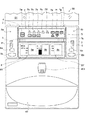
図1〜図3に示すように、本実施形態の手洗い器50は、手洗いボウル45と、その上方に配置された鏡51とを備え、手洗いボウル45と鏡51との間に、入力部7および表示部8を有する表示ユニット4を配置し、人体のインピーダンスを測定するための電極6a,6bを有するセンサユニット5a,5bを表示ユニット4の左右側部にそれぞれ設けている。入力部7および表示部8を有する表示ユニット4と、電極6a,6bを有するセンサユニット5a,5bとによって体脂肪計1が形成されている。   As shown in FIGS. 1 to 3, the hand-washing machine 50 according to the present embodiment includes a hand-washing bowl 45 and a mirror 51 disposed above the hand-washing bowl 45, and the input unit 7 is provided between the hand-washing bowl 45 and the mirror 51. The display unit 4 having the display unit 8 is disposed, and sensor units 5a and 5b having electrodes 6a and 6b for measuring the impedance of the human body are provided on the left and right sides of the display unit 4, respectively. The body fat scale 1 is formed by the display unit 4 having the input unit 7 and the display unit 8 and the sensor units 5a and 5b having the electrodes 6a and 6b.

体脂肪計1は、その背面側に取り付けパネル2を介在させて化粧室(図24参照)などの壁面3に垂直状態に取り付けられる。体脂肪計1は、壁面3に取り付けられる表示ユニット4と、この表示ユニット4に対して起立、倒伏する方向に回動可能(図7(a)参照)に保持された左右2つのセンサユニット5a,5bと、被測定者の人体のインピーダンスを測定するためセンサユニット5a,5bにそれぞれ設けられた電極6a,6bと、を備えている。左右のセンサユニット5a,5bはそれぞれ水平方向に配置された支軸10(図6参照)を中心に回動可能に取り付けられている。   The body fat scale 1 is vertically attached to a wall surface 3 such as a restroom (see FIG. 24) with an attachment panel 2 interposed on the back side thereof. The body fat scale 1 includes a display unit 4 attached to the wall surface 3 and two left and right sensor units 5a held so as to be rotatable with respect to the display unit 4 so as to stand up and fall (see FIG. 7A). , 5b and electrodes 6a, 6b provided on the sensor units 5a, 5b, respectively, for measuring the impedance of the human body of the measurement subject. The left and right sensor units 5a and 5b are attached so as to be rotatable about a support shaft 10 (see FIG. 6) arranged in the horizontal direction.

表示ユニット4の正面上方には、被測定者の身体情報を入力するための入力部7が設けられ、その下方には、体脂肪率などの測定結果を表示する表示部8が配置されている。表示部8は、壁面3と平行な水平方向の支軸(図示せず)を有するヒンジ部9を介して表示ユニット4に対して起立、倒伏する方向に回動可能(図5参照)に取り付けられている。また、左右のセンサユニット5a,5bに設けられた電極6a,6bの上方部分には、被測定者の手の接触位置を規定するための鼻形状の突起部11が設けられている。   An input unit 7 for inputting the body information of the person to be measured is provided above the display unit 4 and a display unit 8 for displaying measurement results such as body fat percentage is disposed below the input unit 7. . The display unit 8 is attached so as to be able to turn up and down with respect to the display unit 4 via a hinge unit 9 having a horizontal support shaft (not shown) parallel to the wall surface 3 (see FIG. 5). It has been. In addition, a nose-shaped protrusion 11 is provided on the upper part of the electrodes 6a and 6b provided on the left and right sensor units 5a and 5b for defining the contact position of the hand of the subject.

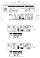
図2に示すように、入力部7には、体脂肪計1や、後述する体重計65や血圧計66の電源をON・OFFするための電源スイッチ7aと、登録者を選択するための複数の選択ボタン7bと、測定モードを選択するための複数のモード切替ボタン7cと、測定結果を記録するための記録ボタン7dと、被測定者のデータ設定モードに切り替えるための個人ボタン7eと、時刻設定モードに切り替えるための時刻ボタン7fと、設定数値を増減させるための数値切替ボタン7h,7iと、増減させた数値に設定データを更新するための更新ボタン7gと、が配置されている。   As shown in FIG. 2, the input unit 7 includes a body fat scale 1, a power switch 7 a for turning on / off power of a weight scale 65 and a blood pressure monitor 66 described later, and a plurality of registrants. Selection button 7b, a plurality of mode switching buttons 7c for selecting the measurement mode, a recording button 7d for recording the measurement result, a personal button 7e for switching to the data setting mode of the measured person, and a time A time button 7f for switching to the setting mode, numerical value switching buttons 7h and 7i for increasing / decreasing the set numerical value, and an update button 7g for updating the setting data to the increased / decreased numerical value are arranged.

また、図2に示すように、表示部8には、測定結果を表示する出力表示部8Xと、設定データを表示する入力表示部8Yとが設けられている。出力表示部8Xには、尿糖値、血圧値および脈拍を表示する液晶パネル8aと、体重値、体脂肪率および肥満程度を表示する液晶パネル8bとが設けられている。入力表示部8Yには、身長、年齢および性別を表示する液晶パネル8cが設けられている。   As shown in FIG. 2, the display unit 8 is provided with an output display unit 8X for displaying the measurement result and an input display unit 8Y for displaying the setting data. The output display unit 8X is provided with a liquid crystal panel 8a that displays a urine sugar value, a blood pressure value, and a pulse, and a liquid crystal panel 8b that displays a body weight value, a body fat percentage, and an obesity level. The input display unit 8Y is provided with a liquid crystal panel 8c that displays height, age, and sex.

一方、図6に示すように、体脂肪計1の表示ユニット4の背面の中央部分には、背面側へ突出したカバー12が複数のネジ14によって取り付けられ、他の機器との間で信号の送受信を行うための複数のキャブタイヤケーブル18が、カバー12の中央下部から下方に向かって延設されている。これらのキャブタイヤケーブル18は押さえ板19およびネジ20によりカバー12に係止されている。カバー12の左右には、センサユニット5a,5bのロックステー15a,15bを構成する固定ヒンジ部材16a,16bにそれぞれ固着された竿旗形状の連結板13a,13bが複数のネジ17によって取り付けられている。これらの連結板13a,13bは剛性の高い金属板で形成されている。   On the other hand, as shown in FIG. 6, a cover 12 protruding to the back side is attached to the center portion of the back side of the display unit 4 of the body fat scale 1 by a plurality of screws 14, and signals are transmitted to other devices. A plurality of cabtire cables 18 for transmitting and receiving are extended downward from the lower center of the cover 12. These cabtyre cables 18 are locked to the cover 12 by pressing plates 19 and screws 20. On the left and right sides of the cover 12, flag-shaped connecting plates 13a and 13b fixed to fixed hinge members 16a and 16b constituting the lock stays 15a and 15b of the sensor units 5a and 5b are attached by a plurality of screws 17, respectively. Yes. These connecting plates 13a and 13b are formed of a highly rigid metal plate.

図2で示したように、表示ユニット4の正面側には、被測定者の身体情報を入力する入力部7と、測定結果を表示する表示部8とが設けられているが、表示ユニット4の内部には、図6に示すように、入力部7から入力された被測定者の身体情報を記憶する記憶部21と、電極6a,6bで測定したインピーダンスと後述する体重計65で測定した体重値および記憶部21に記憶された被測定者の身体情報に基づいて体脂肪率を算出する演算部22とが設けられている。そして、演算部22で算出された体脂肪率を示す数値が表示部8の液晶パネル8bに表示される。   As shown in FIG. 2, on the front side of the display unit 4, an input unit 7 for inputting body information of the person to be measured and a display unit 8 for displaying measurement results are provided. As shown in FIG. 6, the storage unit 21 that stores the body information of the measurement subject input from the input unit 7, the impedance measured by the electrodes 6 a and 6 b, and the weight scale 65 described later are measured. A calculation unit 22 is provided that calculates the body fat percentage based on the body weight value and the physical information of the measurement subject stored in the storage unit 21. A numerical value indicating the body fat percentage calculated by the calculation unit 22 is displayed on the liquid crystal panel 8 b of the display unit 8.

ここで、図9を参照して、体脂肪計1の初期設定手順について説明する。まず、図9(a)に示すように、入力部7にある電源スイッチ7aを押して体脂肪計1を始動させた後、入力部7の個人ボタン7eを押して、被測定者のデータ入力を開始する。個人ボタン7eを押した後、選択ボタン7b(A〜D,ゲスト)のいずれかを押すと、入力表示部8Yの液晶パネル8c中の身長表示部8dが数値「160」を表示して点滅し始めるので、数値切替ボタン7h,7iのいずれかを押して被測定者の身長値と合わせる。被測定者の身長値と同じ数値が表示された後、表示部8の個人ボタン7eを押すと身長が確定される。   Here, an initial setting procedure of the body fat scale 1 will be described with reference to FIG. First, as shown in FIG. 9 (a), after pressing the power switch 7a in the input unit 7 to start the body fat scale 1, the personal button 7e of the input unit 7 is pressed to start data input of the subject. To do. After pressing the personal button 7e, when any of the selection buttons 7b (A to D, guest) is pressed, the height display portion 8d in the liquid crystal panel 8c of the input display portion 8Y displays the numerical value “160” and blinks. Since it starts, it pushes either numerical value switch button 7h, 7i, and unites with the height value of a person to be measured. After the same numerical value as the height value of the person to be measured is displayed, when the individual button 7e of the display unit 8 is pressed, the height is determined.

身長が確定されると、入力表示部8Yの年齢表示部8eが数値「40」を表示して点滅し始めるので、数値切替ボタン7h,7iのいずれかを押して被測定者の年齢値と合わせる。被測定者の年齢値と同じ数値が表示されたら、表示部8の個人ボタン7eを押して年齢を確定する。さらに、年齢が確定されると、入力表示部8Yの年齢表示部8eの直下の性別表示部の「男」か「女」の表示を数値切替ボタン7h,7iを押して切り替えて、性別を設定する。そして、最後に、更新ボタン7gを押して設定を完了する。これにより、初期設定が完了するが、被測定者が複数存在する場合は、各被測定者について前述した手順に沿って初期設定操作を行う。   When the height is confirmed, the age display unit 8e of the input display unit 8Y displays the numerical value “40” and starts to blink, so that either of the numerical value switching buttons 7h and 7i is pressed to match the age value of the subject. When the same numerical value as the age value of the person to be measured is displayed, the individual button 7e of the display unit 8 is pressed to confirm the age. Further, when the age is confirmed, the display of “male” or “female” in the gender display section immediately below the age display section 8e of the input display section 8Y is switched by pressing the numerical value switching buttons 7h, 7i to set the gender. . Finally, the update button 7g is pushed to complete the setting. Thereby, the initial setting is completed, but when there are a plurality of persons to be measured, the initial setting operation is performed for each person to be measured according to the procedure described above.

次に、図10〜図12を参照して、センサユニット5a,5bの構造、機能などについて説明する。図10は図1に示す手洗い器を構成する体脂肪計のセンサユニットの分解斜視図、図11は倒伏姿勢にあるセンサユニットの垂直断面図、図12は最大角度起立姿勢にあるセンサユニットの垂直断面図である。なお、図10〜図12はセンサユニット5aについて記載しているが、センサユニット5bはセンサユニット5aと互いに鏡面対称な構造であり、機能も同じであるため、センサユニット5bについては説明を省略する。   Next, the structure and function of the sensor units 5a and 5b will be described with reference to FIGS. 10 is an exploded perspective view of the sensor unit of the body fat scale constituting the handwasher shown in FIG. 1, FIG. 11 is a vertical sectional view of the sensor unit in the lying posture, and FIG. 12 is a vertical view of the sensor unit in the maximum standing posture. It is sectional drawing. 10 to 12 show the sensor unit 5a, the sensor unit 5b has a mirror-symmetrical structure with the sensor unit 5a and has the same function, and therefore the description of the sensor unit 5b is omitted. .

図10に示すように、センサユニット5aは、連結板13aに固着された固定ヒンジ部材16aと、保護カバー23a,23bと、板状の係止バネ28と、断面コ字状の可動ヒンジ部材24と、上部支軸25aおよび下部支軸25bを有するリンク部材25と、支軸10と、支軸10の両端に係止されるEリング29と、可動ヒンジ部材24に対してこれを覆うように固着される断面コ字状の補強部材26と、電極6a,6bと、電極6a,6bから延設される信号ケーブル30a,30bおよびコネクタ31a,31bと、正面ケース32aと、背面ケース33bと、背面ケース33bの背面側に貼着される半球形状のクッション34と、を備えている。   As shown in FIG. 10, the sensor unit 5a includes a fixed hinge member 16a fixed to the connecting plate 13a, protective covers 23a and 23b, a plate-like locking spring 28, and a movable hinge member 24 having a U-shaped cross section. The link member 25 having the upper support shaft 25a and the lower support shaft 25b, the support shaft 10, the E-ring 29 locked to both ends of the support shaft 10, and the movable hinge member 24 so as to cover it. A fixed U-shaped reinforcing member 26, electrodes 6a and 6b, signal cables 30a and 30b and connectors 31a and 31b extending from the electrodes 6a and 6b, a front case 32a, and a back case 33b; A hemispherical cushion 34 attached to the back side of the back case 33b.

保護カバー23a,23bは固定ヒンジ部材16aの左右両側に付設され、係止バネ28は固定ヒンジ部材16aの内側にネジ(図示せず)で固定され、可動ヒンジ部材24は支軸10を介して固定ヒンジ部材16aに回動可能に取り付けられる。このとき、支軸10は、固定ヒンジ部材16aの上端部分にある支持孔16cと、可動ヒンジ部材24の上端部分にある支持孔24aとを貫通する状態に取り付けられ、その両端部にEリング29が係止される。可動ヒンジ部材24、リンク部材25および補強部材26は高剛性の金属板で形成され、係止バネ28は弾性金属板で形成され、支軸10は金属丸棒材で形成されている。   The protective covers 23 a and 23 b are attached to the left and right sides of the fixed hinge member 16 a, the locking spring 28 is fixed to the inside of the fixed hinge member 16 a with screws (not shown), and the movable hinge member 24 is interposed via the support shaft 10. The fixed hinge member 16a is rotatably attached. At this time, the support shaft 10 is attached so as to pass through the support hole 16c in the upper end portion of the fixed hinge member 16a and the support hole 24a in the upper end portion of the movable hinge member 24, and E-rings 29 are attached to both ends thereof. Is locked. The movable hinge member 24, the link member 25, and the reinforcing member 26 are formed of a highly rigid metal plate, the locking spring 28 is formed of an elastic metal plate, and the support shaft 10 is formed of a metal round bar.

リンク部材25は、固定ヒンジ部材16aと可動ヒンジ部材24との間に配置され、その上部支軸25aの両端部が、可動ヒンジ部材24の左右の支持孔24bにそれぞれ回動可能に軸支され、下部支軸25bの両端部がそれぞれ、固定ヒンジ部材16aの左右のガイドスリット16gに沿って移動可能に取り付けられる。これによって、支軸10を介して固定ヒンジ部材16aに回動可能に軸支された可動ヒンジ部材24と、固定ヒンジ部材16aと可動ヒンジ部材24との間に配置されたリンク部材25とによってロックステー15aが形成される。可動ヒンジ部材24の下部には、複数のネジ孔24cを有する平板状の固定部24dが設けられている。   The link member 25 is disposed between the fixed hinge member 16a and the movable hinge member 24, and both end portions of the upper support shaft 25a are pivotally supported by the left and right support holes 24b of the movable hinge member 24, respectively. The both ends of the lower support shaft 25b are attached so as to be movable along the left and right guide slits 16g of the fixed hinge member 16a. As a result, the movable hinge member 24 pivotally supported by the fixed hinge member 16 a via the support shaft 10 and the link member 25 disposed between the fixed hinge member 16 a and the movable hinge member 24 are locked. A stay 15a is formed. A flat plate-like fixing portion 24 d having a plurality of screw holes 24 c is provided below the movable hinge member 24.

この後、図11に示すように、電極6a,6bが背面から嵌入された正面ケース32aを、補強部材26の正面側からロックステー15a全体を覆うように装着し、補強部材26の背面側から貫通させた複数のネジ36を正面ケース32aのネジ孔32bに螺着させることによって、正面ケース32aをロックステー15aに固定する。そして、背面ケース33bをロックステー15aの背面側から可動ヒンジ部材24の固定部24dに取り付けた後、背面ケース33bの背面側から複数のネジ孔33cにそれぞれネジ35(図4参照)を挿入して、固定部24dのネジ孔24cに螺着すれば、センサユニット5aが形成される。なお、図6,図7および図10に示すように、正面ケース32a,32bの側面に、その内側と連通した円筒状の軸体32cが形成されており、この軸体32cが表示ユニット4の軸受け部4b内に回動可能に緩挿される(図7(b)参照)。また、この円筒状の軸体32cの内部は、図10に示す信号ケーブル30a,30bを表示ユニット4内へ配線する際の配線経路となっている。   Thereafter, as shown in FIG. 11, the front case 32 a in which the electrodes 6 a and 6 b are fitted from the back side is mounted so as to cover the entire lock stay 15 a from the front side of the reinforcing member 26, and from the back side of the reinforcing member 26. The front case 32a is fixed to the lock stay 15a by screwing the plurality of penetrated screws 36 into the screw holes 32b of the front case 32a. Then, after attaching the back case 33b to the fixed portion 24d of the movable hinge member 24 from the back side of the lock stay 15a, screws 35 (see FIG. 4) are respectively inserted into the plurality of screw holes 33c from the back side of the back case 33b. The sensor unit 5a is formed by screwing into the screw hole 24c of the fixing portion 24d. As shown in FIGS. 6, 7, and 10, a cylindrical shaft body 32 c that communicates with the inside of the front cases 32 a and 32 b is formed on the side surfaces of the front cases 32 a and 32 b. It is loosely inserted into the bearing portion 4b so as to be rotatable (see FIG. 7B). Further, the inside of the cylindrical shaft body 32c serves as a wiring path for wiring the signal cables 30a and 30b shown in FIG.

このような構成とすることにより、ロックステー15aを構成する可動ヒンジ部材24は、固定ヒンジ部材16aに対して、支軸10を中心に回動可能となる。従って、可動ヒンジ部材24に固着された補強部材26に取り付けられたセンサユニット5aは、図11に示すように垂下した倒伏状態から図12に示すように最大角度まで起立した状態に至るまでの範囲内において、支軸10を中心に回動可能となる。   With such a configuration, the movable hinge member 24 constituting the lock stay 15a can be rotated around the support shaft 10 with respect to the fixed hinge member 16a. Therefore, the sensor unit 5a attached to the reinforcing member 26 fixed to the movable hinge member 24 has a range from the suspended state as shown in FIG. 11 to the state where it stands up to the maximum angle as shown in FIG. Inside, it becomes possible to rotate around the support shaft 10.

次に、図13〜図18を参照して、ロックステーの構造、機能などについて詳しく説明する。図13はセンサユニットを構成するロックステーの倒伏状態における左側面図、図14は図13に示すロックステーがバネ押し上げ状態に移行したときの左側面図、図15は図14に示すロックステーが最大回転状態に移行したときの左側面図、図16は図15に示すロックステーがロック状態に移行したときの左側面図、図17は図16に示すロックステーがロック解除状態に移行したときの左側面図、図18は図17に示すロックステーが回転途中で係止された状態に移行したときの左側面図である。なお、図13〜図18にはロックステー15bについて記載しているが、ロックステー15aはロックステー15bと互いに鏡面対称な構造であり、機能も同じであるため、ロックステー15aについては説明を省略する。   Next, the structure and function of the lock stay will be described in detail with reference to FIGS. FIG. 13 is a left side view of the lock stay constituting the sensor unit in the lying down state, FIG. 14 is a left side view when the lock stay shown in FIG. 13 is shifted to the spring-up state, and FIG. 15 is a view of the lock stay shown in FIG. FIG. 16 is a left side view when the lock stay shown in FIG. 15 is shifted to the locked state, and FIG. 17 is a view when the lock stay shown in FIG. 16 is shifted to the unlocked state. FIG. 18 is a left side view when the lock stay shown in FIG. 17 is shifted to a locked state during rotation. Although FIG. 13 to FIG. 18 show the lock stay 15b, the lock stay 15a has a mirror-symmetrical structure with the lock stay 15b and has the same function, and therefore the description of the lock stay 15a is omitted. To do.

図13は、ロックステー15bを構成する可動ヒンジ部材24が倒伏状態にあるときを示しており、この状態が、後述する第1の測定姿勢となる。図13においては、図11で示したロックステー15aには現れていない、係止バネ28および誘導部材37が示されている。係止バネ28は、図10で示したように、略く字状の板バネであり、固定ヒンジ部材16bの内側に固定されている。誘導部材37は、金属板で形成された略ブーメラン形状の部材であり、その一方の端部が支軸38を介して固定ヒンジ部材16bの左側面に回動可能に軸支されている。また、誘導部材37の回動範囲を矢印40の範囲内に規定するため、その中央部分に設けられた係止孔41と、係止孔41内に突出した状態で固定ヒンジ部材16bの側面に固定された係止ピン39とが設けられている。また、図13の状態にあるとき、リンク部材25の下部支軸25bは、係止バネ28の下方を背面方向(連結板13b方向)へ押圧するとともに、係止バネ28の反作用により下部支軸25bは正面方向へ付勢されている。   FIG. 13 shows a state in which the movable hinge member 24 constituting the lock stay 15b is in a lying state, and this state is a first measurement posture described later. FIG. 13 shows the locking spring 28 and the guide member 37 that do not appear in the lock stay 15a shown in FIG. As shown in FIG. 10, the locking spring 28 is a substantially rectangular plate spring and is fixed to the inside of the fixed hinge member 16 b. The guide member 37 is a substantially boomerang-shaped member formed of a metal plate, and one end portion of the guide member 37 is pivotally supported on the left side surface of the fixed hinge member 16b via a support shaft 38. Further, in order to define the rotation range of the guide member 37 within the range of the arrow 40, a locking hole 41 provided in the center portion thereof, and a side of the fixed hinge member 16b in a state of protruding into the locking hole 41 A fixed locking pin 39 is provided. In the state shown in FIG. 13, the lower support shaft 25 b of the link member 25 presses the lower side of the locking spring 28 in the rear direction (direction of the connecting plate 13 b) and the lower support shaft by the reaction of the locking spring 28. 25b is urged in the front direction.

誘導部材37は内角側には2つの凸部37a,37bと2つの湾部37c,37dとが設けられ、凸部37bおよび湾部37c,37dが、固定ヒンジ部材16bのガイドスリット16gの上端部にある略三角形状の拡幅部16hに臨むように配置されている。誘導部材37はバネ(図示せず)によって支軸38を中心に反時計方向(凸部37aが連結板13bに接近する方向)に付勢されているため、外力が加わらない限り、図13に示す状態に保たれる。   The guide member 37 is provided with two convex portions 37a and 37b and two bay portions 37c and 37d on the inner corner side, and the convex portion 37b and the bay portions 37c and 37d are the upper ends of the guide slits 16g of the fixed hinge member 16b. It is arranged so as to face the substantially triangular widened portion 16h. Since the guide member 37 is biased counterclockwise (the direction in which the convex portion 37a approaches the connecting plate 13b) about the support shaft 38 by a spring (not shown), unless an external force is applied, the guide member 37 is shown in FIG. Kept in the state shown.

ここで、図14に示すように、支軸10を中心に可動ヒンジ部材24を上方に回動させて、元の位置から99度まで起立させると、リンク部材25がその上部支軸25aを中心に回動しながら可動ヒンジ部材24とともに上昇し、その下部支軸25bは係止バネ28から離脱して、固定ヒンジ部材16bのガイドスリット16gに沿って上昇し、拡幅部16h内へ進入する。拡幅部16h内へ進入した下部支軸25bは、誘導部材37の湾部37d内へ入った後、凸部37bを押し上げるため、誘導部材37は支軸38を中心に矢印42方向へ回動していく。なお、下部支軸25bが上昇して係止バネ28から離脱することにより、係止バネ28は原形に復元し、その下方は正面方向に移動する。   Here, as shown in FIG. 14, when the movable hinge member 24 is pivoted upward about the support shaft 10 to stand up to 99 degrees from the original position, the link member 25 is centered on the upper support shaft 25a. The lower support shaft 25b separates from the locking spring 28, rises along the guide slit 16g of the fixed hinge member 16b, and enters the widened portion 16h. The lower support shaft 25b that has entered the widened portion 16h enters the bay portion 37d of the guide member 37, and then pushes up the convex portion 37b. Therefore, the guide member 37 rotates about the support shaft 38 in the direction of the arrow 42. To go. When the lower support shaft 25b is lifted and separated from the locking spring 28, the locking spring 28 is restored to its original shape, and the lower part thereof moves in the front direction.

この後、更に可動ヒンジ部材24を上方へ回動させると、リンク部材25の下部支軸25bが凸部37bを押し上げるので、誘導部材37は支軸38を中心に更に矢印42方向へ回動していくが、下部支軸25bが凸部37bの頂上を乗り越えると、誘導部材37は付勢力によって直ちに矢印42と逆方向に回動して元の状態に戻る。即ち、図15に示すように、可動ヒンジ部材24を上方へ最大限まで回動させると、下部支軸25bがガイドスリット16gの拡幅部16hの上端コーナー部16iに達し、誘導部材37は矢印43方向に回動して、その湾部37cが下部支軸25bに当接した状態となる。なお、本実施形態では、可動ヒンジ部材24の最大回動角度を元の位置から110度に設定しているが、これに限定するものではない。   Thereafter, when the movable hinge member 24 is further rotated upward, the lower support shaft 25b of the link member 25 pushes up the convex portion 37b, so that the guide member 37 is further rotated around the support shaft 38 in the direction of the arrow 42. However, when the lower support shaft 25b gets over the top of the convex portion 37b, the guide member 37 is immediately rotated in the direction opposite to the arrow 42 by the urging force to return to the original state. That is, as shown in FIG. 15, when the movable hinge member 24 is rotated upward as much as possible, the lower support shaft 25b reaches the upper end corner portion 16i of the widened portion 16h of the guide slit 16g, and the guide member 37 moves to the arrow 43. Rotating in the direction, the bay portion 37c comes into contact with the lower support shaft 25b. In the present embodiment, the maximum rotation angle of the movable hinge member 24 is set to 110 degrees from the original position, but the present invention is not limited to this.

この後、可動ヒンジ部材24に加えている上向きの力を解除すると、可動ヒンジ部材24は支軸10を中心に倒伏方向へ回動するが、このとき、図15に示す状態にある下部支軸25bは、誘導部材37の湾部37cから凸部37bの上縁に沿って下降していき、図16に示すように、ガイドスリット16gの拡幅部16hの後端コーナー部16jに入り込み、ここに係止される。これにより、リンク部材25は固定ヒンジ部材16bと可動ヒンジ部材24との間に動かないように拘束されるため、可動ヒンジ部材24はもとの位置から90度起立した状態でリンク部材25によってロックされる。   Thereafter, when the upward force applied to the movable hinge member 24 is released, the movable hinge member 24 rotates about the support shaft 10 in the lying down direction. At this time, the lower support shaft in the state shown in FIG. 25b descends from the bay portion 37c of the guide member 37 along the upper edge of the convex portion 37b, and enters the rear end corner portion 16j of the widened portion 16h of the guide slit 16g as shown in FIG. Locked. As a result, the link member 25 is constrained so as not to move between the fixed hinge member 16b and the movable hinge member 24. Therefore, the movable hinge member 24 is locked by the link member 25 in a state in which the link member 25 stands 90 degrees from the original position. Is done.

この後、図17に示すように、可動ヒンジ部材24を上方に回動させると、リンク部材25も同時に上昇するため、その下部支軸25bは拡幅部16hの後端コーナー部16jから離脱するが、直ちに誘導部材37の凸部37bの下縁に当接し、それに沿って誘導されながら湾部37dに入り込み、ガイドスリット16gの上方部分に位置する。本実施形態では、このときの可動ヒンジ部材24の起立角度を元の位置から100度に設定しているが、これに限定するものではない。   Thereafter, as shown in FIG. 17, when the movable hinge member 24 is rotated upward, the link member 25 is also raised at the same time, so that the lower support shaft 25b is detached from the rear end corner portion 16j of the widened portion 16h. Immediately abut against the lower edge of the convex portion 37b of the guide member 37, and enters the bay portion 37d while being guided along it, and is positioned in the upper portion of the guide slit 16g. In the present embodiment, the standing angle of the movable hinge member 24 at this time is set to 100 degrees from the original position, but the present invention is not limited to this.

図17に示す状態において、リンク部材25の下部支軸25bはそのままガイドスリット16gに沿って下降可能であるため、可動ヒンジ部材24を支えている力を緩めると、可動ヒンジ部材24は自重により倒伏方向へ回動していく。これに伴い、リンク部材25の下部支軸25bはガイドスリット16gに沿って下降していくが、その下方には、原形に戻った係止バネ28の下方部分が位置している。このため、図18に示すように、下部支軸25bが係止バネ28の下方部分に当接した時点でその下降が阻止され、その位置でリンク部材25が拘束される。これにより、可動ヒンジ部材24の回転が止まり、その状態で保持されるため、可動ヒンジ部材24が自重で倒伏状態まで一挙に回動するのを防止することができる。本実施形態では、このときの可動ヒンジ部材24の元の位置からの起立角度を45度に設定しているが、これに限定するものではない。   In the state shown in FIG. 17, since the lower support shaft 25b of the link member 25 can be lowered as it is along the guide slit 16g, if the force supporting the movable hinge member 24 is loosened, the movable hinge member 24 will fall by its own weight. Rotate in the direction. Along with this, the lower support shaft 25b of the link member 25 descends along the guide slit 16g, but below that, the lower portion of the locking spring 28 that has returned to its original shape is located. For this reason, as shown in FIG. 18, when the lower support shaft 25b comes into contact with the lower portion of the locking spring 28, the lowering is prevented and the link member 25 is restrained at that position. Thereby, since the rotation of the movable hinge member 24 is stopped and held in that state, it is possible to prevent the movable hinge member 24 from rotating at once to its fallen state due to its own weight. In the present embodiment, the standing angle from the original position of the movable hinge member 24 at this time is set to 45 degrees, but the present invention is not limited to this.

この後、可動ヒンジ部材24に斜め下向きの力を加えて倒伏方向に回動させれば、リンク部材25の下部支軸25bが係止バネ28の付勢力に打ち勝って、係止バネ28を背面方向(連結板13b方向)へ押し込むように弾性変形させながら、ガイドスリット16gに沿って下降していくため、可動ヒンジ部材24を図13に示す元の倒伏状態まで戻すことができる。この後、再び可動ヒンジ部材24を起立方向に回動させれば、前述した図14〜図18に示す状態を反復することができる。なお、図13に示す状態においては、係止バネ28が下部支軸25bを正面側へ付勢することにより、下部支軸25bは軽く拘束された状態に保たれている。このため、振動や接触などにより、可動ヒンジ部材24が勝手に揺動するのを防ぐことができる。   Thereafter, if a downward force is applied to the movable hinge member 24 to rotate in the lying down direction, the lower support shaft 25b of the link member 25 overcomes the urging force of the locking spring 28, and the locking spring 28 is moved back. Since it descends along the guide slit 16g while being elastically deformed so as to be pushed in the direction (direction of the connecting plate 13b), the movable hinge member 24 can be returned to the original lying state shown in FIG. Thereafter, if the movable hinge member 24 is rotated again in the standing direction, the above-described states shown in FIGS. 14 to 18 can be repeated. In the state shown in FIG. 13, the locking spring 28 urges the lower support shaft 25b toward the front side, so that the lower support shaft 25b is kept lightly constrained. For this reason, it is possible to prevent the movable hinge member 24 from freely swinging due to vibration or contact.

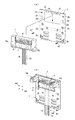
次に、図3〜図6および図19を参照して、図3などに示す体脂肪計1を壁面に取り付ける方法について説明する。図19は図1に示す手洗い器を構成する体脂肪計の取り付け手順を示す斜視図である。図19に示すように、体脂肪計1は、その背面側に取り付けパネル2を介在させてトイレ(図示せず)などの壁面に固定して使用される。取り付けパネル2は、長方形をした金属製の板材の外周部を背面側(壁面側)に曲面状に折り曲げ、その上方部分に長方形の開口部2aを設けて形成したものである。取り付けパネル2の四隅寄りの部分および中央部の左右の複数箇所には、板材を背面側(壁面側)に凹ませるとともに、そこにネジ挿入用の貫通孔2bが設けられている。また、開口部2aの左右には、後述するネジ44を通すための複数の貫通孔2dが設けられている。   Next, a method for attaching the body fat scale 1 shown in FIG. 3 and the like to the wall surface will be described with reference to FIGS. FIG. 19 is a perspective view showing a procedure for attaching the body fat scale constituting the hand washing machine shown in FIG. As shown in FIG. 19, the body fat scale 1 is used by being fixed to a wall surface of a toilet (not shown) or the like with an attachment panel 2 interposed on the back side thereof. The mounting panel 2 is formed by bending an outer peripheral portion of a rectangular metal plate material into a curved surface on the back side (wall surface side) and providing a rectangular opening 2a at an upper portion thereof. A plate material is recessed on the back side (wall surface side) at a portion near the four corners of the mounting panel 2 and at a central portion, and through holes 2b for screw insertion are provided there. A plurality of through-holes 2d are provided on the left and right sides of the opening 2a to allow screws 44 described later to pass therethrough.

図19(a)に示すように、体脂肪計1の設置場所となる壁面(図示せず)に取り付けパネル2を配置し、その正面側から複数の貫通孔2bにそれぞれネジ47を挿入し、壁面に対して螺着すると、取り付けパネル2が壁面に固定される。この後、体脂肪計1の背面を取り付けパネル2に向け、キャブタイヤケーブル18を取り付けパネル2の開口部2aを通って下方へ配線し、図4,図5に示すように、表示ユニット4の背面部4aを開口部44a内に嵌め込むとともにフック2cに引っ掛ける。   As shown in FIG. 19 (a), the mounting panel 2 is arranged on a wall surface (not shown) as a place where the body fat scale 1 is installed, and screws 47 are respectively inserted into the plurality of through holes 2b from the front side thereof. When screwed to the wall surface, the mounting panel 2 is fixed to the wall surface. Thereafter, the back of the body fat scale 1 is directed to the mounting panel 2, and the cabtyre cable 18 is routed downward through the opening 2a of the mounting panel 2, and as shown in FIGS. The back surface portion 4a is fitted into the opening 44a and hooked on the hook 2c.

この後、図19(b)に示すように、左右のセンサユニット5a,5bを上方に回動させ90度起立状態にする。このとき、センサユニット5a,5b内のロックステー15a,15bが図11〜図14で示したように作動することによってセンサユニット5a,5bが90度起立状態に保たれる。センサユニット5a,5bを90度起立状態とすると、連結板13a,13bの正面部分が現れるため、そこに開設された複数の貫通孔13c(図4参照)に対して、正面側からそれぞれネジ44を挿入し、そのまま取り付けパネル2の貫通孔2dを通して壁面に螺着する。即ち、取り付けパネル2の貫通孔2dと、連結板13a,13bの貫通孔13cとは、体脂肪計1を取り付けパネル2に装着したとき、同軸上で重なり合うように開設されているため、ネジ44を貫通孔13cに挿入すれば、そのまま貫通孔2dを連通して壁面に螺着することができる。全ての貫通孔13cに対するネジ44の螺着が終われば、体脂肪計1の取り付けが完了する。そして、体脂肪計1を取り付けた取付パネル2の下方領域には、給水栓45aを備えた手洗いボウル45が取り付けられる。   Thereafter, as shown in FIG. 19 (b), the left and right sensor units 5a and 5b are rotated upward to stand 90 degrees. At this time, the lock stays 15a and 15b in the sensor units 5a and 5b are operated as shown in FIGS. 11 to 14, so that the sensor units 5a and 5b are kept upright by 90 degrees. When the sensor units 5a and 5b are raised by 90 degrees, the front portions of the connecting plates 13a and 13b appear, so that the plurality of through-holes 13c (see FIG. 4) opened there are respectively screwed 44 from the front side. Is inserted into the wall surface through the through hole 2d of the mounting panel 2 as it is. That is, since the through hole 2d of the mounting panel 2 and the through hole 13c of the connecting plates 13a and 13b are opened so as to overlap on the same axis when the body fat scale 1 is mounted on the mounting panel 2, the screw 44 Is inserted into the through hole 13c, the through hole 2d can be directly communicated and screwed to the wall surface. When the screw 44 is completely screwed into all the through holes 13c, the attachment of the body fat scale 1 is completed. And the hand-washing bowl 45 provided with the water tap 45a is attached to the downward area | region of the attachment panel 2 to which the body fat scale 1 was attached.

次に、図3および図20〜図23を参照して、体脂肪計1の使い方について説明する。図20は図3に示す手洗い器の一部切欠左側面図、図21は図20に示す体脂肪計のセンサユニットを起立させたときの斜視図、図22は図21に示す手洗い器の一部切欠左側面図、図23は図22に示す体脂肪計のセンサユニットが倒伏途中で係止されたときの一部切欠左側面図である。   Next, how to use the body fat scale 1 will be described with reference to FIG. 3 and FIGS. 20 is a partially cutaway left side view of the hand-washing machine shown in FIG. 3, FIG. 21 is a perspective view when the sensor unit of the body fat scale shown in FIG. 20 is raised, and FIG. 22 is a view of the hand-washing machine shown in FIG. FIG. 23 is a partially cutaway left side view when the sensor unit of the body fat scale shown in FIG. 22 is locked in the middle of lying down.

待機状態にある体脂肪計1は、図3および図20に示す状態となっている。被測定者は、電源スイッチ7aを押して起動させた後、複数の選択ボタン7bのうち、自分に対応する選択ボタン7bを押す。そして、図21,図22に示すように、左右のセンサユニット5a,5bを水平方向に起立した姿勢にする。この場合、図20に示す倒伏状態にあるセンサユニット5a,5bを手で掴んで、その状態から一旦110度の位置まで回動させた後、手を離せば、センサユニット5a,5bは自動的に水平姿勢となる。この過程においては、センサユニット5a,5bに内蔵されたロックステー15a,15bが図13〜図16で示したように作動し、固定ヒンジ部材16a,16bと可動ヒンジ部材(図示せず)との間にリンク部材25が係合することによってセンサユニット5a,5bがロックされて水平姿勢に保たれる。このロック状態が第1の測定姿勢となる。   The body fat scale 1 in the standby state is in the state shown in FIGS. 3 and 20. The subject to be measured presses the power switch 7a to start up, and then presses the selection button 7b corresponding to the user among the plurality of selection buttons 7b. Then, as shown in FIGS. 21 and 22, the left and right sensor units 5 a and 5 b are placed in a standing posture in the horizontal direction. In this case, if the sensor units 5a and 5b in the lying state shown in FIG. 20 are gripped by hand and rotated to a position of 110 degrees from that state, the sensor units 5a and 5b are automatically activated when the hands are released. It becomes a horizontal posture. In this process, the lock stays 15a and 15b built in the sensor units 5a and 5b operate as shown in FIGS. 13 to 16, and the fixed hinge members 16a and 16b and a movable hinge member (not shown) are operated. When the link member 25 is engaged therebetween, the sensor units 5a and 5b are locked and kept in a horizontal posture. This locked state is the first measurement posture.

そして、図21に示すように、表示部8を上方に回動させ、被測定者が液晶パネル8a,8b,8cを見やすい傾斜角度にセットする。図7(b)で示したように、表示部8は倒伏状態から水平起立状態の範囲内で任意の傾斜角度にセットすることができるため、被測定者の目の高さに応じた適切な状態とすることができる。   Then, as shown in FIG. 21, the display unit 8 is rotated upward, and the measurement subject is set at an inclination angle at which the liquid crystal panels 8a, 8b, and 8c are easy to see. As shown in FIG. 7B, the display unit 8 can be set to an arbitrary inclination angle within the range from the lying state to the horizontal standing state. State.

センサユニット5a,5bおよび表示部8のセットが完了したら、被測定者は左右の手の平を下にして、水平状態にあるセンサユニット5a,5bの上面に載せる。このとき、センサユニット5a,5bの上面にある突起部11をそれぞれ左右の手の人差し指と中指との間の指股で挟むとともに、両手の平を電極6a,6bに密着させる。この後は、自動的に被測定者の人体のインピーダンスが測定され、それに基づいて演算部22(図6参照)で算出された体脂肪率および肥満程度などが表示部8の液晶パネル8bに表示される。   When the setting of the sensor units 5a, 5b and the display unit 8 is completed, the person to be measured places the left and right palms on the upper surfaces of the sensor units 5a, 5b in a horizontal state. At this time, the protrusions 11 on the upper surfaces of the sensor units 5a and 5b are sandwiched between the index and middle fingers of the left and right hands, and the palms of both hands are brought into close contact with the electrodes 6a and 6b. Thereafter, the impedance of the human body of the person to be measured is automatically measured, and the body fat rate and the degree of obesity calculated by the calculation unit 22 (see FIG. 6) based on the impedance are displayed on the liquid crystal panel 8b of the display unit 8. Is done.

体脂肪率の測定が終わったら、センサユニット5a,5bを水平姿勢から上に回動させると、倒伏姿勢から100度に達した位置で、図17で示したように、リンク部材25の下部軸体25bが、ガイドスリット16gの拡幅部16hの後端コーナー部16jから離脱してガイドスリット16gの上方に移動する。従って、この状態でセンサユニット5a,5bを支えている力を緩めるか、手を離せば、センサユニット5a,5bは自重で倒伏方向へ回動するが、図18で示したように、リンク部材25の下部軸体25bが係止バネ28に当接するため、その位置でセンサユニット5a,5bの回動が止まり、その状態に保持される。そこで、この後、センサユニット5a,5bに力を加えて倒伏方向に回動させれば、下部軸体25bが係止バネ28を背面側へ押し込みながらガイドスリット16gに沿って下降していき、センサユニット5a,5bは、図3,図20に示す倒伏状態に戻る。この後、電源スイッチ7aを押せば、電源がOffされ、体脂肪計1は待機状態となる。   When the measurement of the body fat percentage is finished, when the sensor units 5a and 5b are rotated upward from the horizontal posture, the lower shaft of the link member 25 is positioned at a position reaching 100 degrees from the lying posture as shown in FIG. The body 25b separates from the rear end corner portion 16j of the widened portion 16h of the guide slit 16g and moves above the guide slit 16g. Accordingly, if the force supporting the sensor units 5a and 5b is loosened or the hands are released in this state, the sensor units 5a and 5b rotate in the lying down direction due to their own weights. However, as shown in FIG. Since the lower shaft body 25b of the 25 abuts against the locking spring 28, the rotation of the sensor units 5a and 5b stops at that position and is held in that state. Therefore, after that, if force is applied to the sensor units 5a and 5b to rotate in the lying down direction, the lower shaft body 25b descends along the guide slit 16g while pushing the locking spring 28 toward the back side, The sensor units 5a and 5b return to the lying down state shown in FIGS. Thereafter, if the power switch 7a is pressed, the power is turned off and the body fat scale 1 enters a standby state.

一方、体脂肪計1は、図3,図20に示すように、センサユニット5a,5bが倒伏状態にあるときでも体脂肪率の測定を行うことができる。即ち、電源スイッチ7aを押して電源をONした後、倒伏状態にあるセンサユニット5a,5bの突起部11および電極6a,6bに対して、水平起立状態にしたときと同じ要領で被測定者の左右の手の平を密着させれば、自動的に人体のインピーダンスが測定され、演算部22(図8参照)で算出された体脂肪率が液晶パネル8bに表示される。このように、センサユニット5a,5bを倒伏させた状態においても体脂肪率の測定を行うことができるため、身長の低い被測定者でも楽な姿勢で正確な測定を行うことができる。   On the other hand, as shown in FIGS. 3 and 20, the body fat scale 1 can measure the body fat percentage even when the sensor units 5a and 5b are lying down. That is, after the power switch 7a is pressed and the power is turned on, the left and right sides of the subject are measured in the same manner as when the protrusions 11 and the electrodes 6a and 6b of the sensor units 5a and 5b in the lying state are horizontally raised. When the palm of the hand is brought into close contact, the impedance of the human body is automatically measured, and the body fat percentage calculated by the calculation unit 22 (see FIG. 8) is displayed on the liquid crystal panel 8b. Thus, since the body fat percentage can be measured even in the state where the sensor units 5a and 5b are laid down, even a measurement subject with a short height can perform an accurate measurement with an easy posture.

前述したように、体脂肪計1は、壁面3に取り付けられる表示ユニット4と、この表示ユニット4に対して起立、倒伏する方向に回動可能に保持された2つのセンサユニット5a,5bと、人体のインピーダンスを測定するためセンサユニット5a,5bにそれぞれ設けられた電極6a,6bとを備えている。従って、被測定者は、センサユニット5a,5bを起立姿勢または倒伏姿勢のいずれかにセットし、左右の手の平を、電極6a,6bに密着する程度に、センサユニット5a,5bに押し当てるだけで、体脂肪率の測定を行うことができる。このため、正しい姿勢で体脂肪率の測定を行うことができ、測定精度の向上も図ることができる。   As described above, the body fat scale 1 includes the display unit 4 attached to the wall surface 3, and the two sensor units 5a and 5b held so as to be rotatable with respect to the display unit 4 so as to stand and fall. In order to measure the impedance of the human body, electrodes 6a and 6b provided on the sensor units 5a and 5b, respectively, are provided. Therefore, the person to be measured simply sets the sensor units 5a and 5b to either the standing posture or the lying posture, and presses the left and right palms against the sensor units 5a and 5b to the extent that they are in close contact with the electrodes 6a and 6b. The body fat percentage can be measured. For this reason, the body fat percentage can be measured in the correct posture, and the measurement accuracy can be improved.

また、センサユニット5a,5bを起立状態に保持するため、固定ヒンジ部材16a,16b、可動ヒンジ部材24およびリンク部材25からなるロック機構をそれぞれロックステー15a,15bに設けている。従って、センサユニット5a,5bを倒伏姿勢、起立姿勢の2つの姿勢で安定的に保持可能であり、身長の高い人はセンサユニット5a,5bを起立状態に保持して測定し、身長の低い人はセンサユニット5a,5bを倒伏状態に保持して測定することができる。このため、各人の身長差に対応して、身体的負担の少ない楽な姿勢で測定することができる。   Further, in order to hold the sensor units 5a and 5b in an upright state, lock mechanisms including fixed hinge members 16a and 16b, a movable hinge member 24 and a link member 25 are provided in the lock stays 15a and 15b, respectively. Accordingly, the sensor units 5a and 5b can be stably held in the two postures of the lying posture and the standing posture, and a person with a high height is measured while holding the sensor units 5a and 5b in a standing state. Can be measured while holding the sensor units 5a, 5b in a lying state. For this reason, it can measure with an easy posture with little physical burden corresponding to each person's height difference.

さらに、図18,図23で示したように、ロック機構のロック状態を解除したとき、センサユニット5a,5bが自重で倒伏姿勢まで回動するのを防止する緩衝手段として、ロックステー15a,15bを構成するリンク部材25の下部軸体25bの昇降領域に係止バネ28を設けている。従って、起立状態にあるセンサユニット5a,5bが、ロック解除後、自重で一気に倒伏状態まで戻ること、および倒伏状態に戻る際にセンサユニット5a,5bの構成部材と周辺部材とが衝突することを回避することができる。このため、騒音の発生、部材の損傷を防ぐことができ、安全性も向上する。また、図6,図11,図12で示したように、センサユニット5a,5bの背面ケース33bには半球状のクッション34を設けているため、センサユニット5a,5bが倒伏状態に戻るとき、最初にクッション34が取り付けパネル2に当接することにより、衝撃を緩和することができる。   Further, as shown in FIGS. 18 and 23, the lock stays 15a and 15b serve as buffering means for preventing the sensor units 5a and 5b from rotating to the lying posture by their own weight when the lock mechanism is unlocked. A locking spring 28 is provided in the ascending / descending region of the lower shaft body 25b of the link member 25 constituting the. Therefore, the sensor units 5a and 5b in the standing state return to the fallen state at a stretch by their own weight after unlocking, and the constituent members of the sensor units 5a and 5b and the peripheral members collide when returning to the fallen state. It can be avoided. For this reason, generation | occurrence | production of a noise and damage to a member can be prevented and safety | security improves. Further, as shown in FIGS. 6, 11, and 12, since the rear case 33b of the sensor units 5a and 5b is provided with a hemispherical cushion 34, when the sensor units 5a and 5b return to the lying state, First, the cushion 34 can come into contact with the mounting panel 2 to reduce the impact.

一方、センサユニット5a,5bに設けられた電極6a,6bの近傍に、被測定者の手の接触位置を規定するための突起部11を設けているため、この突起部を基準にして、被測定者の手が常に一定の位置へ置かれるようになり、測定精度のさらなる向上を図ることができる。   On the other hand, a projection 11 for defining the contact position of the hand of the person to be measured is provided in the vicinity of the electrodes 6a and 6b provided on the sensor units 5a and 5b. The measurer's hand is always placed at a fixed position, and the measurement accuracy can be further improved.

さらに、図2,図8で示したように、表示ユニット4は、被測定者の身体情報を入力する入力部7と、入力された身体情報を記憶する記憶部21と、電極6a,6bで測定したインピーダンスと後述する体重計65で測定した体重値および記憶部21に記憶された被測定者の身体情報に基づいて体脂肪率を算出する演算部22と、演算部22により算出された体脂肪率を表示する表示部8と、を備えている。このため、被測定者の体脂肪率の算出に必要なデータをその場で入力することが可能であり、使い方も容易であり、利便性に優れている。   Further, as shown in FIGS. 2 and 8, the display unit 4 includes an input unit 7 for inputting physical information of the measurement subject, a storage unit 21 for storing the input physical information, and electrodes 6a and 6b. A calculation unit 22 that calculates a body fat percentage based on the measured impedance, a body weight value measured by a weight scale 65 described later, and the body information of the measurement subject stored in the storage unit 21, and a body calculated by the calculation unit 22 And a display unit 8 for displaying the fat percentage. For this reason, it is possible to input the data necessary for calculating the body fat percentage of the measurement subject on the spot, the usage is easy, and the convenience is excellent.

また、本実施形態の手洗い器50においては、体脂肪率の測定結果を表示する表示部8が鏡51の下方に位置し、体脂肪率を測定するためのセンサユニット5a,5bが表示部8の左右側部に位置した状態となるので、より簡便に体脂肪率を測定できるだけでなく、体脂肪率の測定をしながら、被測定者の正面にある鏡51で身体チェックを行うことが可能であり、使い勝手が良好である。また、後述するように、比較的スペースの狭い化粧室内においても容易に使用することができる。   Further, in the hand washing machine 50 of the present embodiment, the display unit 8 that displays the measurement result of the body fat percentage is located below the mirror 51, and the sensor units 5a and 5b for measuring the body fat percentage are the display unit 8. Since the body fat percentage can be measured more easily, the body can be checked with the mirror 51 in front of the subject while measuring the body fat percentage. It is easy to use. Further, as will be described later, it can be easily used even in a bathroom with a relatively small space.

さらに、手洗い器50においては、鉛直面に対する表示部8の仰角を変更可能な角度調節機構を設けているため、表示部8を被測定者の身長に適した仰角に設定することが可能であり、表示内容を容易かつ確実に視認することができる。前述したように、センサユニット5a,5bを、鉛直面に対して起立、倒伏する方向に回動可能に保持する回動機構を設けているため、被測定者の身長に応じてセンサユニット5a,5bを回動させることにより、適切な姿勢で測定可能となるため、測定者が無理な姿勢を強いられることがなくなり、測定精度も向上する。   Furthermore, since the hand-washing machine 50 is provided with an angle adjustment mechanism that can change the elevation angle of the display unit 8 with respect to the vertical plane, the display unit 8 can be set to an elevation angle suitable for the height of the person being measured. The displayed contents can be easily and reliably visually recognized. As described above, since the rotation mechanism that holds the sensor units 5a and 5b so that the sensor units 5a and 5b can stand up and down with respect to the vertical surface is provided, the sensor units 5a and 5b are arranged according to the height of the person being measured. By rotating 5b, it becomes possible to measure in an appropriate posture, so that the measurer is not forced to take an unreasonable posture, and the measurement accuracy is improved.

一方、図20に示すように、背面部に配線用領域2zを有する取り付けパネル2を壁面3に沿って付設し、この取り付けパネル2の正面部に手洗いボウル45および表示ユニット4を取り付け、表示ユニット4と他の機器とを結ぶ配線であるキャブタイヤケーブル18を取り付けパネル2の配線用領域2zに配置している。従って、表示ユニット4と他の機器とを結ぶ配線の隠蔽処理が簡便となり、施工が容易となり、施工後の外観性も優れている。   On the other hand, as shown in FIG. 20, a mounting panel 2 having a wiring region 2z on the back surface is provided along the wall surface 3, and a hand-washing bowl 45 and a display unit 4 are mounted on the front surface of the mounting panel 2 to display the display unit. A cabtyre cable 18, which is a wiring connecting 4 and other devices, is arranged in the wiring area 2 z of the mounting panel 2. Therefore, the concealing process of the wiring connecting the display unit 4 and other devices becomes simple, the construction becomes easy, and the appearance after construction is excellent.

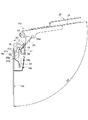
次に、図24〜図26を参照し、手洗い器50が配置された化粧室について説明する。図24は図1に示す手洗い器が配置された化粧室を示す斜視図、図25は図24に示す化粧室の側壁部を示す図、図26は図24に示す化粧室の平面図である。   Next, with reference to FIGS. 24-26, the restroom where the hand-washing machine 50 is arrange | positioned is demonstrated. 24 is a perspective view showing a restroom in which the hand washing machine shown in FIG. 1 is arranged, FIG. 25 is a view showing a side wall of the restroom shown in FIG. 24, and FIG. 26 is a plan view of the restroom shown in FIG. .

粧室60は、複数の側壁61,62,63で区画された領域内に大便器64および複数の健康測定器である体脂肪計1、床埋め込み式の体重計65および血圧計66を備えている。化粧室60を構成する第一の側壁61に大便器64が設けられ、この側壁61と交差して隣接する第二の側壁62に、手洗いボウル45とその上方に配置された鏡51とを備えた手洗い器50が配置されている。そして、データ入力部7と、体脂肪計1、体重計65および血圧計66による計測結果を有線あるいは無線で受信して表示する表示部8とを有する表示ユニット4を手洗いボウル45と鏡51との間に配置している。さらに、人体のインピーダンスを測定する電極6a,6b(図2参照)を有するセンサユニット5a,5bを表示ユニット4の左右側部にそれぞれ設け、さらに、大便器64に向かう位置に出入口67が設けられている。
Of粧室60, the body fat meter 1 is flush toilet 64 and a plurality of health measuring devices, the bed sunken weight scale 65 and the sphygmomanometer 66 includes a compartmented regions by a plurality of side walls 61, 62, 63 ing. A toilet 64 is provided on the first side wall 61 constituting the restroom 60, and a hand wash bowl 45 and a mirror 51 disposed above the toilet bowl 45 are provided on a second side wall 62 that intersects and is adjacent to the side wall 61. A hand washing machine 50 is arranged. Then, the display unit 4 having the data input unit 7 and the display unit 8 for receiving and displaying the measurement results of the body fat scale 1, the weight scale 65, and the sphygmomanometer 66 by wire or wirelessly displays the hand washing bowl 45 and the mirror 51. It is arranged between. Furthermore, sensor units 5a and 5b having electrodes 6a and 6b (see FIG. 2) for measuring the impedance of the human body are provided on the left and right sides of the display unit 4, respectively, and an entrance 67 is provided at a position toward the toilet 64. ing.

このような構成とすれば、体脂肪率の測定結果を表示する表示部8が鏡51の下方に位置し、体脂肪率を測定するためのセンサユニット5a,5bが表示部8の左右側部に位置した状態となるので、より簡便に体脂肪率を測定可能となるだけでなく、体脂肪率の測定をしながら、測定者の正面にある鏡51で身体チェックを行うことが可能となり、使い勝手が向上する。また、スペースの限られた狭い化粧室60内においても、用便の邪魔にならない位置(大便器64の側方)に体脂肪率の測定機構をコンパクトに集約することができる。   With such a configuration, the display unit 8 that displays the measurement result of the body fat percentage is positioned below the mirror 51, and the sensor units 5a and 5b for measuring the body fat percentage are the left and right side parts of the display unit 8. Since the body fat percentage can be measured more easily, it is possible to perform a body check with the mirror 51 in front of the measurer while measuring the body fat percentage. Usability is improved. In addition, even in a small restroom 60 where space is limited, the body fat percentage measurement mechanism can be compactly integrated at a position that does not obstruct the stool (the side of the toilet 64).

なお、体重計65は、入力部7の電源スイッチ7aをONすると、キャリブレーションを補正して計測可能な状態となり、その上に乗るだけで体重を測定することができる。しかしながら、化粧室内での人の移動により、体重計65に乗り降りするたびに体重測定されてしまうことは非効率的なので、電源スイッチ7aの投入後、最初に測定した体重を真の体重とみなして、体脂肪率の算出に用いることとしている。なお、その体重を計り直す場合には、入力部7内の「体重」スイッチを押して、体重計をリセットすればよい。   When the power switch 7a of the input unit 7 is turned on, the weight scale 65 is in a state where the calibration is corrected and can be measured, and the weight can be measured simply by riding on the weight scale 65. However, since it is inefficient to measure the weight every time when getting on and off the scale 65 due to the movement of the person in the bathroom, the first measured weight after the power switch 7a is turned on is regarded as the true weight. The body fat percentage is used for calculation. In order to remeasure the weight, the weight scale may be reset by pressing the “weight” switch in the input unit 7.

一方、図27に示す化粧室60aにおいては、図26で示した化粧室60における配管スペースPSをサイズダウンすることにより、化粧室60a全体のコンパクト化を図ったものである。また、図28に示す化粧室60bにおいては、配管スペースをなくすことにより、化粧室60b全体をさらにコンパクト化している。   On the other hand, in the restroom 60a shown in FIG. 27, the entire restroom 60a is made compact by reducing the size of the piping space PS in the restroom 60 shown in FIG. Further, in the restroom 60b shown in FIG. 28, the entire restroom 60b is further downsized by eliminating the piping space.

次に、図29〜図31に示す化粧室60c,60d,60eにおいては、手洗い器50を構成する鏡51に隣接させてカウンタ付きの血圧計66が設けられている。このような構成とすることにより、第三の側壁に出入口67aを設けた化粧室においても複数の健康測定器を好適に配設することができる。   Next, in the restrooms 60c, 60d, and 60e shown in FIGS. 29 to 31, a blood pressure monitor 66 with a counter is provided adjacent to the mirror 51 that constitutes the hand-washing machine 50. By adopting such a configuration, a plurality of health measuring devices can be suitably arranged even in a restroom provided with the entrance / exit 67a on the third side wall.

また、図32に示す化粧室60fは浴室68に隣接して設けられ、その側壁64に配置された洗面器48の上方に表示ユニット4およびセンサユニット5a,5bからなる体脂肪計1が配置され、この体脂肪計1の上方に鏡51が配置されている。そして、洗面器48の手前の床面に体重計65が配置され、側壁64の隅に洗濯機69が配置されている。このように、大便器を配設しない化粧室(洗面所)においても、複数の健康測定器を好適に配設することができる。   32 is provided adjacent to the bathroom 68, and the body fat scale 1 including the display unit 4 and the sensor units 5a and 5b is disposed above the wash basin 48 disposed on the side wall 64 thereof. A mirror 51 is disposed above the body fat scale 1. A weight scale 65 is disposed on the floor surface in front of the basin 48, and a washing machine 69 is disposed in the corner of the side wall 64. Thus, even in a restroom (toilet) where no toilet is provided, a plurality of health measuring devices can be suitably provided.

次に、図33に示す化粧室は、複数の側壁で区画された領域内に複数の健康測定器を備えた化粧室であって、この化粧室を構成する第一側壁61に大便器64を配置し、第一の側壁61と交差して隣接する第二の側壁62に、手洗いボウル45とその上方に配置された鏡51とを備えた手洗い器70を配置し、データ入力部7と、健康測定器による計測結果を有線あるいは無線で受信して表示する表示部8とを有する表示ユニット4を手洗いボウル45と鏡51との間に配置し、人体のインピーダンスを測定する電極を有するセンサユニット5a,5bを鏡51の左右側部にそれぞれ設けている。   Next, the restroom shown in FIG. 33 is a restroom provided with a plurality of health measuring devices in an area partitioned by a plurality of side walls, and a toilet 64 is provided on the first side wall 61 constituting the restroom. A handwasher 70 having a handwashing bowl 45 and a mirror 51 disposed above the second side wall 62 that intersects and is adjacent to the first side wall 61, the data input unit 7; A sensor unit having an electrode for measuring the impedance of a human body by disposing a display unit 4 having a display unit 8 for receiving and displaying a result of measurement by a health measuring device in a wired or wireless manner between a hand-washing bowl 45 and a mirror 51. 5a and 5b are provided on the left and right sides of the mirror 51, respectively.

このような構成とすることにより、図5に示した実施の形態の化粧室と同じ作用効果を得ることができる。さらに、センサユニット5a,5bを鏡51の左右側部に設けているため、鏡の下端をより下方に配置することが可能となり、背の低い人でも容易に鏡51を使うことができる。   By adopting such a configuration, it is possible to obtain the same operational effects as the restroom of the embodiment shown in FIG. Furthermore, since the sensor units 5a and 5b are provided on the left and right side portions of the mirror 51, the lower end of the mirror can be arranged further downward, and the mirror 51 can be easily used even by a short person.

次に、図34は、図32に示した化粧室の一側面図であり、複数の側壁で区画された領域内に複数の健康測定器を備えた化粧室であって、洗面器48とその上方に配置された鏡51とを有する洗面台71を側壁62に設置し、データ入力部7と、健康測定器による測定結果を有線あるいは無線で受信して表示する表示部8とを備えた表示ユニット4を洗面器48と鏡51との間に配置し、人体のインピーダンスを測定する電極を有するセンサユニット5a,5bを表示ユニット4の左右側部にそれぞれ設けている。このような構成とすることにより、図25に示した実施形態の化粧室と同じ作用効果が得られる。   Next, FIG. 34 is a side view of the restroom shown in FIG. 32, which is a restroom equipped with a plurality of health measuring devices in an area partitioned by a plurality of side walls, and includes a washbasin 48 and its washbasin 48. A display provided with a wash basin 71 having a mirror 51 disposed on the side wall 62, a data input unit 7, and a display unit 8 for receiving and displaying a measurement result by a health measuring device in a wired or wireless manner. The unit 4 is disposed between the wash basin 48 and the mirror 51, and sensor units 5a and 5b having electrodes for measuring the impedance of the human body are provided on the left and right sides of the display unit 4, respectively. By adopting such a configuration, the same operational effects as the restroom of the embodiment shown in FIG. 25 can be obtained.

次に、図35に示す化粧室は、図34に示す化粧室の変形例であり、複数の側壁で区画された領域内に複数の健康測定器を備えた化粧室であって、洗面器48とその上方に配置された鏡51とを有する洗面台72を側壁62に設置し、データ入力部7と、健康測定器による測定結果を有線あるいは無線で受信して表示する表示部8とを備えた表示ユニット4を洗面器48と鏡51との間に設置し、人体のインピーダンスを測定する電極を有するセンサユニット5a,5bを鏡51の左右側部にそれぞれ設けている。   Next, the restroom shown in FIG. 35 is a modification of the restroom shown in FIG. 34, and is a restroom equipped with a plurality of health measuring devices in a region partitioned by a plurality of side walls, and a wash basin 48. A wash basin 72 having a mirror 51 disposed thereon and a side wall 62, a data input unit 7, and a display unit 8 for receiving and displaying a measurement result by a health measuring device in a wired or wireless manner. The display unit 4 is installed between the wash basin 48 and the mirror 51, and sensor units 5a and 5b having electrodes for measuring the impedance of the human body are provided on the left and right sides of the mirror 51, respectively.

このような構成とすることにより、図25に示した化粧室と同様の作用効果を得ることができる。また、センサユニット5a,5bを鏡51の左右側部に設けているため、鏡51の下端をより下方に配置することが可能であり、背の低い人でも容易に鏡51を使用することができる。   By adopting such a configuration, it is possible to obtain the same effect as that of the restroom shown in FIG. In addition, since the sensor units 5a and 5b are provided on the left and right sides of the mirror 51, the lower end of the mirror 51 can be arranged further downward, so that even a short person can easily use the mirror 51. it can.

本発明の手洗い器は、一般住宅における健康管理設備として広く利用することができる。
The hand-washing machine of the present invention can be widely used as a health management facility in ordinary houses.

本発明の実施の形態である手洗い器を示す正面図である。It is a front view which shows the hand-washing machine which is embodiment of this invention. 図1に示す手洗い器の部分拡大図である。It is the elements on larger scale of the hand-washing machine shown in FIG. 図1に示す手洗い器の部分斜視図である。It is a fragmentary perspective view of the hand-washing machine shown in FIG. 図1に示す手洗い器を構成する体脂肪計の右側面図である。It is a right view of the body fat scale which comprises the hand-washing machine shown in FIG. 図1に示す手洗い器を構成する体脂肪計の底面図である。It is a bottom view of the body fat scale which comprises the hand-washing machine shown in FIG. 図1に示す手洗い器を構成する体脂肪計の背面図である。It is a rear view of the body fat scale which comprises the hand-washing machine shown in FIG. (a)は図1に示す手洗い器を構成する体脂肪計におけるセンサユニットの起伏状態を示す右側面図であり、(b)は図1に示す手洗い器を構成する体脂肪計における表示部の起伏状態を示す一部省略右側面図である。(A) is a right view which shows the undulation state of the sensor unit in the body fat scale which comprises the hand-washing machine shown in FIG. 1, (b) is a display part in the body fat scale which comprises the hand-washing machine shown in FIG. It is a partially omitted right side view showing the undulation state. 図1に示す手洗い器を構成する体脂肪計の表示ユニットの概略構成を示す図である。It is a figure which shows schematic structure of the display unit of the body fat scale which comprises the hand-washing machine shown in FIG. 図1に示す手洗い器を構成する体脂肪計の設定方法を示す説明図である。It is explanatory drawing which shows the setting method of the body fat scale which comprises the hand-washing machine shown in FIG. 図1に示す手洗い器を構成する体脂肪計のセンサユニットの分解斜視図である。It is a disassembled perspective view of the sensor unit of the body fat scale which comprises the hand-washing machine shown in FIG. 倒伏姿勢にあるセンサユニットの垂直断面図である。It is a vertical sectional view of the sensor unit in the lying posture. 最大角度起立姿勢にあるセンサユニットの垂直断面図である。It is a vertical sectional view of the sensor unit in the maximum angle standing posture. センサユニットを構成するロックステーが倒伏状態にあるときの左側面図である。It is a left view when the lock stay which comprises a sensor unit is in a lying state. 図13に示すロックステーがバネ押し上げ状態に移行したときの左側面図である。FIG. 14 is a left side view when the lock stay shown in FIG. 13 is shifted to a spring-up state. 図14に示すロックステーが最大回転状態に移行したときの左側面図である。It is a left view when the lock stay shown in FIG. 14 transfers to the maximum rotation state. 図15に示すロックステーがロック状態に移行したときの左側面図である。FIG. 16 is a left side view when the lock stay shown in FIG. 15 is shifted to a locked state. 図16に示すロックステーがロック解除状態に移行したときの左側面図である。It is a left view when the lock stay shown in FIG. 16 transfers to the unlocking state. 図17に示すロックステーが倒伏途中で係止された状態に移行したときの左側面図である。FIG. 18 is a left side view when the lock stay shown in FIG. 17 is shifted to a state of being locked in the middle of lying down. 図1に示す手洗い器を構成する体脂肪計の取付手順を示す斜視図である。It is a perspective view which shows the attachment procedure of the body fat scale which comprises the hand-washing machine shown in FIG. 図1に示す手洗い器を構成する体脂肪計が壁面に取り付けられた状態を示す一部切欠左側面図である。It is a partially cutaway left view which shows the state in which the body fat scale which comprises the hand-washing machine shown in FIG. 1 was attached to the wall surface. 図3に示す手洗い器を構成する体脂肪計のセンサユニットを起立させたときの一部省略斜視図である。It is a partially-omission perspective view when standing up the sensor unit of the body fat scale which comprises the hand-washing machine shown in FIG. 図21に示す体脂肪計の一部切欠左側面図である。It is a partially cutaway left view of the body fat scale shown in FIG. 図22に示す体脂肪計のセンサユニットが倒伏途中で係止されたときの一部切欠左側面図である。It is a partially cutaway left side view when the sensor unit of the body fat scale shown in FIG. 22 is locked in the middle of lying down. 図1に示す手洗い器が配置された化粧室を示す斜視図である。It is a perspective view which shows the restroom where the hand-washing machine shown in FIG. 1 is arrange | positioned. 図24に示す化粧室の側壁部を示す図である。It is a figure which shows the side wall part of the restroom shown in FIG. 図24に示す化粧室の平面図である。It is a top view of the restroom shown in FIG. 図1に示す手洗い器が配置されたその他の化粧室の平面図である。Is a plan view of the other of粧室that hand washing device is arranged as shown in FIG. 図1に示す手洗い器が配置されたその他の化粧室の平面図である。Is a plan view of the other of粧室that hand washing device is arranged as shown in FIG. 図1に示す手洗い器が配置されたその他の化粧室の平面図である。Is a plan view of the other of粧室that hand washing device is arranged as shown in FIG. 図1に示す手洗い器が配置されたその他の化粧室の平面図である。Is a plan view of the other of粧室that hand washing device is arranged as shown in FIG. 図1に示す手洗い器が配置されたその他の化粧室の平面図である。Is a plan view of the other of粧室that hand washing device is arranged as shown in FIG. 参考例である洗面室の平面図である。It is a top view of the washroom which is a reference example . 本発明のその他の実施の形態である手洗い器が配置された化粧室の側壁部を示す図である。It is a figure which shows the side wall part of the restroom where the hand-washing machine which is other embodiment of this invention is arrange | positioned . 参考例である化粧室の側壁部を示す図である。It is a figure which shows the side wall part of the restroom which is a reference example . 図34に示す化粧室の変形例である化粧室の側壁部を示す図である。It is a figure which shows the side wall part of the restroom which is a modification of the restroom shown in FIG.

符号の説明Explanation of symbols

1 体脂肪計
2 取り付けパネル
2a 開口部
2b,2d,13c 貫通孔
2c フック
2z 配線用領域
3 壁面
4 表示ユニット
4a 背面部
4b 軸受部
5a,5b センサユニット
6a,6b 電極
7 入力部
7a 電源スイッチ
7b 選択ボタン
7c モード切替ボタン
7d 記録ボタン
7e 個人ボタン
7f 時刻ボタン
7g 更新ボタン
7h,7i 数値切替ボタン
8 表示部
8a,8b,8c 液晶パネル
8d 身長表示部
8e 年齢表示部
8X 出力表示部
8Y 入力表示部
9 ヒンジ部
10 支軸
11 突起部
12 カバー
13a,13b 連結板
13g ガイドスリット
14,17,20,35,36,44,47 ネジ
15a,15b ロックステー
16a,16b 固定ヒンジ部材
16c,24a,24b 支持孔
16g ガイドスリット
16h 拡幅部
16i 上端コーナー部
16j 後端コーナー部
18 キャブタイヤケーブル
19 押さえ板
21 記憶部
22 演算部
23a,23b 保護カバー
24 可動ヒンジ部材
24c,32b,33c ネジ孔
24d 固定部
25 リンク部材
25a 上部支軸
25b 下部支軸
26 補強部材
28 係止バネ
29 Eリング
30a,30b 信号ケーブル
31a,31b コネクタ
32a,32b 正面ケース
32c 軸体
33b 背面ケース
34 クッション
37 誘導部材
37a,37b 凸部
37c,37d 湾部
38 支軸
39 係止ピン
41 係止孔
44a 開口部
45 手洗いボウル
45a 給水栓
48 洗面器
50,70 手洗い器
51 鏡
60,60a,60b,60c,60d,60e,60f 化粧室
61,62,63,64 側壁
64 大便器
65 体重計
66 血圧計
67,67a 出入口
68 浴室
69 洗濯機
71,72 洗面台
DESCRIPTION OF SYMBOLS 1 Body fat scale 2 Mounting panel 2a Opening part 2b, 2d, 13c Through-hole 2c Hook 2z Wiring area | region 3 Wall surface 4 Display unit 4a Back surface part 4b Bearing part 5a, 5b Sensor unit 6a, 6b Electrode 7 Input part 7a Power switch 7b Selection button 7c Mode switch button 7d Record button 7e Personal button 7f Time button 7g Update button 7h, 7i Numerical value switch button 8 Display unit 8a, 8b, 8c Liquid crystal panel 8d Height display unit 8e Age display unit 8X Output display unit 8Y Input display unit DESCRIPTION OF SYMBOLS 9 Hinge part 10 Support shaft 11 Protrusion part 12 Cover 13a, 13b Connection board 13g Guide slit 14, 17, 20, 35, 36, 44, 47 Screw 15a, 15b Lock stay 16a, 16b Fixed hinge member 16c, 24a, 24b Support Hole 16g Guide slit 1 6h Widening part 16i Upper end corner part 16j Rear end corner part 18 Cab tire cable 19 Holding plate 21 Storage part 22 Calculation part 23a, 23b Protective cover 24 Movable hinge member 24c, 32b, 33c Screw hole 24d Fixed part 25 Link member 25a Upper support Shaft 25b Lower support shaft 26 Reinforcing member 28 Locking spring 29 E-ring 30a, 30b Signal cable 31a, 31b Connector 32a, 32b Front case 32c Shaft body 33b Rear case 34 Cushion 37 Guide member 37a, 37b Protruding portion 37c, 37d Bay portion 38 Support shaft 39 Locking pin 41 Locking hole 44a Opening 45 Hand wash bowl 45a Water faucet 48 Wash basin 50, 70 Hand wash 51 Mirror 60, 60a, 60b, 60c, 60d, 60e, 60f Restroom 61, 62, 63 , 64 Side wall 6 Toilet bowl 65 weight scale 66 blood pressure meter 67,67a doorway 68 bathrooms 69 washing machines 71 and 72 wash basin

Claims (4)

手洗いボウルと、その上方に配置された鏡とを備えた手洗い器において、前記手洗いボウルと前記鏡との間に、少なくとも入力部および表示部を有する表示ユニットを配置し、人体のインピーダンスを測定するための電極を有するセンサユニットを前記表示ユニットの左右側部にそれぞれ設け、背面部に配線用領域を有する取り付けパネルを壁面に沿って付設し、前記取り付けパネルの正面部に前記手洗いボウルおよび前記表示ユニットを取り付け、前記表示ユニットと他の部材とを結ぶ配線を前記取り付けパネルの配線用領域に配置したことを特徴とする手洗い器。 In a hand-washing machine including a hand-washing bowl and a mirror disposed above the hand-washing bowl, a display unit having at least an input unit and a display unit is arranged between the hand-washing bowl and the mirror, and the impedance of the human body is measured. A sensor unit having electrodes for the left and right sides of the display unit, and a mounting panel having a wiring area on the back surface along the wall surface, and the hand-washing bowl and the display on the front part of the mounting panel A hand-washing machine characterized in that a unit is attached and wiring connecting the display unit and another member is arranged in a wiring area of the mounting panel . 手洗いボウルと、その上方に配置された鏡とを備えた手洗い器において、前記手洗いボウルと前記鏡との間に、少なくとも入力部および表示部を有する表示ユニットを配置し、人体のインピーダンスを測定するための電極を有するセンサユニットを前記鏡の左右側部にそれぞれ設け、背面部に配線用領域を有する取り付けパネルを壁面に沿って付設し、前記取り付けパネルの正面部に前記手洗いボウルおよび前記表示ユニットを取り付け、前記表示ユニットと他の部材とを結ぶ配線を前記取り付けパネルの配線用領域に配置したことを特徴とする手洗い器。 In a hand-washing machine including a hand-washing bowl and a mirror disposed above the hand-washing bowl, a display unit having at least an input unit and a display unit is arranged between the hand-washing bowl and the mirror, and the impedance of the human body is measured. Sensor units having electrodes for the mirrors are provided on the left and right sides of the mirror, respectively , and a mounting panel having a wiring area on the back is provided along the wall surface. The hand-washing bowl and the display unit are provided on the front of the mounting panel. And a wiring connecting the display unit and another member is disposed in the wiring area of the mounting panel . 鉛直面に対する前記表示部の仰角を変更可能な角度調節機構を設けたことを特徴とする請求項1または2記載の手洗い器。   The hand washing machine according to claim 1 or 2, further comprising an angle adjustment mechanism capable of changing an elevation angle of the display unit with respect to a vertical plane. 前記センサユニットを、鉛直面に対して起立、倒伏する方向に回動可能に保持する回動機構を設けたことを特徴とする請求項1〜3のいずれかに記載の手洗い器。   The hand-washing machine according to any one of claims 1 to 3, further comprising a rotation mechanism that holds the sensor unit so as to be rotatable in a direction to stand and fall on a vertical surface.
JP2005090140A 2005-03-25 2005-03-25 Hand washing machine Expired - Fee Related JP4660242B2 (en)

Priority Applications (1)

Application Number Priority Date Filing Date Title
JP2005090140A JP4660242B2 (en) 2005-03-25 2005-03-25 Hand washing machine

Applications Claiming Priority (1)

Application Number Priority Date Filing Date Title
JP2005090140A JP4660242B2 (en) 2005-03-25 2005-03-25 Hand washing machine

Publications (3)

Publication Number Publication Date
JP2006263391A JP2006263391A (en) 2006-10-05
JP2006263391A5 JP2006263391A5 (en) 2007-11-08
JP4660242B2 true JP4660242B2 (en) 2011-03-30

Family

ID=37199940

Family Applications (1)

Application Number Title Priority Date Filing Date
JP2005090140A Expired - Fee Related JP4660242B2 (en) 2005-03-25 2005-03-25 Hand washing machine

Country Status (1)

Country Link
JP (1) JP4660242B2 (en)

Cited By (1)

* Cited by examiner, † Cited by third party
Publication number Priority date Publication date Assignee Title
CN106502108A (en) * 2015-09-07 2017-03-15 青岛经济技术开发区海尔热水器有限公司 Electric appliance for bathroom system and the data managing method based on electric appliance for bathroom system

Families Citing this family (1)

* Cited by examiner, † Cited by third party
Publication number Priority date Publication date Assignee Title
JP4957197B2 (en) * 2006-06-26 2012-06-20 カシオ計算機株式会社 Keyboard device

Citations (5)

* Cited by examiner, † Cited by third party
Publication number Priority date Publication date Assignee Title
JPH04361741A (en) * 1991-06-06 1992-12-15 Toto Ltd Physical fat meter installing structure
JPH0538073U (en) * 1991-10-15 1993-05-21 東陶機器株式会社 Toilet washbasin
JPH07204114A (en) * 1994-01-19 1995-08-08 Inax Corp Wash board
JPH10234690A (en) * 1997-02-24 1998-09-08 Matsushita Electric Works Ltd Body fat meter
JP2004195710A (en) * 2002-12-17 2004-07-15 Konica Minolta Holdings Inc Image forming apparatus

Patent Citations (5)

* Cited by examiner, † Cited by third party
Publication number Priority date Publication date Assignee Title
JPH04361741A (en) * 1991-06-06 1992-12-15 Toto Ltd Physical fat meter installing structure
JPH0538073U (en) * 1991-10-15 1993-05-21 東陶機器株式会社 Toilet washbasin
JPH07204114A (en) * 1994-01-19 1995-08-08 Inax Corp Wash board
JPH10234690A (en) * 1997-02-24 1998-09-08 Matsushita Electric Works Ltd Body fat meter
JP2004195710A (en) * 2002-12-17 2004-07-15 Konica Minolta Holdings Inc Image forming apparatus

Cited By (1)

* Cited by examiner, † Cited by third party
Publication number Priority date Publication date Assignee Title
CN106502108A (en) * 2015-09-07 2017-03-15 青岛经济技术开发区海尔热水器有限公司 Electric appliance for bathroom system and the data managing method based on electric appliance for bathroom system

Also Published As

Publication number Publication date
JP2006263391A (en) 2006-10-05

Similar Documents

Publication Publication Date Title
US6403897B1 (en) Seat scale for health care measurement kiosk
JP5209044B2 (en) Weight and / or motion sensing in bed
US20130334851A1 (en) Kiosk with seat assembly
JP4607611B2 (en) Biological information measurement panel, biological information measuring device, and biological information measuring method
JP4660242B2 (en) Hand washing machine
KR102031019B1 (en) Toilet seat device
JPH09119859A (en) Body weight meter
JP4042756B2 (en) Body fat scale
JP2008206831A (en) Washing/dressing stand
TWI702328B (en) Toilet seat device
JP2006017560A (en) Health control system
JP2007130284A (en) Blood pressure measuring instrument and blood pressure measurement system
JP4443335B2 (en) Portable health care device
JP2006271407A (en) Support mechanism of body fat percentage measuring sensor
CN211834355U (en) Remote auxiliary diagnosis equipment
JP2000060819A (en) Adipometer
KR200328178Y1 (en) Toilet seat device and bidet device using the toilet seat device
TW201417793A (en) Medical monitor system
JP3849504B2 (en) Toilet equipment
WO2010150402A1 (en) Device for allowing supine operator to operate notebook personal computer
EP2878261A1 (en) A system for monitoring the state of a subject
JP4479557B2 (en) Toilet counter with sphygmomanometer
JPH04367638A (en) Stool provided with weight measuring function
JP5300561B2 (en) Biological measuring device
JP2000116613A (en) Body fat meter

Legal Events

Date Code Title Description
A521 Written amendment

Free format text: JAPANESE INTERMEDIATE CODE: A523

Effective date: 20070919

A621 Written request for application examination

Free format text: JAPANESE INTERMEDIATE CODE: A621

Effective date: 20070919

A131 Notification of reasons for refusal

Free format text: JAPANESE INTERMEDIATE CODE: A131

Effective date: 20100601

A521 Written amendment

Free format text: JAPANESE INTERMEDIATE CODE: A523

Effective date: 20100728

A711 Notification of change in applicant

Free format text: JAPANESE INTERMEDIATE CODE: A711

Effective date: 20100730

A521 Written amendment

Free format text: JAPANESE INTERMEDIATE CODE: A821

Effective date: 20100730

TRDD Decision of grant or rejection written
A01 Written decision to grant a patent or to grant a registration (utility model)

Free format text: JAPANESE INTERMEDIATE CODE: A01

Effective date: 20101214

A01 Written decision to grant a patent or to grant a registration (utility model)

Free format text: JAPANESE INTERMEDIATE CODE: A01

A61 First payment of annual fees (during grant procedure)

Free format text: JAPANESE INTERMEDIATE CODE: A61

Effective date: 20101228

FPAY Renewal fee payment (event date is renewal date of database)

Free format text: PAYMENT UNTIL: 20140107

Year of fee payment: 3

R150 Certificate of patent or registration of utility model

Free format text: JAPANESE INTERMEDIATE CODE: R150

R250 Receipt of annual fees

Free format text: JAPANESE INTERMEDIATE CODE: R250

R250 Receipt of annual fees

Free format text: JAPANESE INTERMEDIATE CODE: R250

R250 Receipt of annual fees

Free format text: JAPANESE INTERMEDIATE CODE: R250

LAPS Cancellation because of no payment of annual fees