JP4659476B2 - Interferometer lens support device - Google Patents
Interferometer lens support device Download PDFInfo
- Publication number
- JP4659476B2 JP4659476B2 JP2005031840A JP2005031840A JP4659476B2 JP 4659476 B2 JP4659476 B2 JP 4659476B2 JP 2005031840 A JP2005031840 A JP 2005031840A JP 2005031840 A JP2005031840 A JP 2005031840A JP 4659476 B2 JP4659476 B2 JP 4659476B2
- Authority
- JP
- Japan
- Prior art keywords
- lens
- test
- lens support
- optical axis
- pedestal
- Prior art date
- Legal status (The legal status is an assumption and is not a legal conclusion. Google has not performed a legal analysis and makes no representation as to the accuracy of the status listed.)
- Expired - Fee Related
Links
Images


Description
本発明は、基準面と被検レンズの被検面との双方に測定光を照射し、各々の面からの反射光の干渉によって生じる干渉縞を測定する干渉計に用いられる被検レンズの支持装置に関するものである。 The present invention supports a test lens used in an interferometer that irradiates both a reference surface and a test surface of a test lens with measurement light and measures interference fringes caused by interference of reflected light from each surface. It relates to the device.
レンズ面の仕上がり精度を評価するために干渉計が広く用いられている。例えばレーザ光を測定光に用いたフィゾー型干渉計では、基準レンズを通してレーザ光を被検レンズに照射し、基準レンズの基準面からの反射光と被検レンズの被検面からの反射光とを互いに干渉させ、そこに発生する干渉縞の本数や形状に基づいて被検面の仕上がり度合いを確認することができる。 Interferometers are widely used to evaluate the finished accuracy of the lens surface. For example, in a Fizeau interferometer that uses laser light as measurement light, a test lens is irradiated with laser light through a reference lens, and reflected light from the reference surface of the reference lens and reflected light from the test surface of the test lens Can be confirmed, and the finished degree of the test surface can be confirmed based on the number and shape of interference fringes generated there.
このような干渉計を用いて被検レンズの被検面を評価するに際しては、基準面の曲率中心と被検面の曲率中心とを測定光軸上の一点で合致させることが不可欠である。一般に、基準レンズは干渉計の光学系内に精度良く位置決めされているので問題はないが、被検レンズは干渉計のマウント部にその都度セットされることになるため、その位置決めをいかに簡便かつ正確に行うかということが重要なポイントになる。こうした背景から、例えば特許文献1で知られるように、一般には被検レンズの被検面を測定光軸に関して回転対称な三点で受け止め、被検レンズをその自重を利用して位置決めすることが行われている。
上記レンズ支持装置のように、被検レンズをその自重を利用して三点で支持する場合、被検面をできるだけ安定に支持するとともに、測定エリアを広くとることができるように被検面の外周縁近くでレンズ支持部が被検面を受け止めるようにしている。このように、被検面を三点で受け止めて被検レンズを支持するようにしておけば、被検面の曲率半径によらず被検レンズを簡便かつ正しく位置決めすることができる。 When the test lens is supported at three points using its own weight as in the lens support device, the test surface is supported so that the test surface is supported as stably as possible and the measurement area can be widened. The lens support portion receives the test surface near the outer periphery. In this way, if the test surface is received at three points to support the test lens, the test lens can be easily and correctly positioned regardless of the radius of curvature of the test surface.
しかしながら、特許文献1記載の被検レンズ支持装置では、被検面を三点で受け止めるそれぞれのレンズ支持部が被検面の外周縁近傍で固定されているため、被検レンズの外径に伴って被検面の外径が変わってくるとそのままでは利用することができない。したがって、被検レンズの種類に応じて種々のレンズ支持装置を準備しておかなくてはならず、また新規な被検レンズに対しては新たなレンズ支持装置を作成するという手間がかかり、即応性の点で不十分であった。 However, in the test lens support device described in Patent Document 1, each lens support that receives the test surface at three points is fixed in the vicinity of the outer peripheral edge of the test surface. If the outer diameter of the test surface changes, it cannot be used as it is. Therefore, various lens support devices must be prepared according to the type of lens to be tested, and it takes time and effort to create a new lens support device for new test lenses. It was insufficient in terms of sex.
本発明は上記事情を考慮してなされたもので、被検レンズの外径が変わっても即座に対応が可能な干渉計の被検レンズ支持装置を提供することを目的とする。 The present invention has been made in consideration of the above circumstances, and an object of the present invention is to provide a test lens support device for an interferometer that can respond immediately even if the outer diameter of the test lens changes.
本発明は上記目的を達成するために、干渉計の基準ステージ上に設置され測定光を通過させる開口を形成した台座に三本のレンズ支持アームを組み付け、これらのレンズ支持アームを変位させて各々の先端部が測定光の光軸と略直交する面内で前記開口に出入りするようにしてある。レンズ支持アームの先端部には上方に突出したレンズ支持部材が設けられ、上方から載置される被検レンズの被検面を測定光の光軸と略直交する平面内の三点でほとんど摩擦のない状態で支持する。したがって、被検面が球面であれば被検レンズはその自重により被検面が面内変位する方向でのみ変位して所定の姿勢で落ち着き、被検面が測定光の光軸に正対した測定位置に位置決めされる。このように被検面を三点で支持すれば、被検面の面内変位量自体は測定に何ら影響を与えることがなく、被検面の曲率中心を常に測定光の光軸に合わせた状態で被検レンズを位置決めすることができる。なお、レンズ支持部材は厳密な意味で測定光の光軸と直交する同一の面内になくてもよいが、外径によらず被検面の測定エリアを広くとるには被検面の外周縁近くをレンズ支持部材で支持できるように、レンズ支持部材をできるだけ測定光の光軸と直交する面内に沿って移動させるのがよい。 In order to achieve the above object, the present invention has three lens support arms assembled on a pedestal that is installed on a reference stage of an interferometer and has an opening for allowing measurement light to pass therethrough, and these lens support arms are displaced, respectively. The front end of the light enters and exits the opening within a plane substantially perpendicular to the optical axis of the measurement light. A lens support member protruding upward is provided at the tip of the lens support arm, and the test surface of the test lens placed from above is almost frictional at three points in a plane substantially perpendicular to the optical axis of the measurement light. Support in the absence of Therefore, if the test surface is a spherical surface, the test lens is displaced only in the direction in which the test surface is displaced in-plane by its own weight and settles in a predetermined posture, and the test surface faces the optical axis of the measurement light. Positioned at the measurement position. If the test surface is supported at three points in this way, the in-plane displacement amount of the test surface itself does not affect the measurement, and the center of curvature of the test surface is always aligned with the optical axis of the measurement light. The test lens can be positioned in the state. The lens support member does not have to be in the same plane orthogonal to the optical axis of the measurement light in a strict sense. However, in order to increase the measurement area of the test surface regardless of the outer diameter, the lens support member must be located outside the test surface. It is preferable to move the lens support member along a plane orthogonal to the optical axis of the measurement light as much as possible so that the vicinity of the periphery can be supported by the lens support member.
三本のレンズ支持アームは、好ましくは測定光の光軸に関して回転対称となる位置で前記台座に組み付けられ、かつ前記光軸からの距離が等しくなるように前記開口内に一斉に出入りするように構成される。三本のレンズ支持アームを上記のように変位させる連動機構は、レンズ支持アームの後端に設けられたカムフォロアを台座に形成されたカムに係合させ、そして台座に回転自在に組み付けられた回転リングにレンズ支持アームの中間部を回転自在に軸支させることによって構成することができる。さらに、レンズ支持アームの上方にレンズ支持アームと同様に変位する三本のレンズ押さえアームを設け、これらのレンズ押さえアームの先端部に光軸と平行に下方に延びるように外周押さえ部材を突設しておく。レンズ押さえアームを適切な位置に変位させておくことによって、被検面に沿って被検レンズがレンズ支持部材の上で滑ったとしても、被検レンズの外周面が前記外周押さえ部材によって受け止められるから、被検レンズをレンズ支持部材から不用意に落下させるといった事故を防ぐことができるようになる。 The three lens support arms are preferably assembled to the pedestal at a position that is rotationally symmetric with respect to the optical axis of the measurement light, and so that the distance from the optical axis is the same so as to enter and exit the opening all at once. Composed. The interlocking mechanism that displaces the three lens support arms as described above is such that the cam follower provided at the rear end of the lens support arm is engaged with the cam formed on the pedestal, and the rotation is rotatably assembled to the pedestal. The intermediate portion of the lens support arm can be rotatably supported on the ring. In addition, three lens pressing arms that displace in the same manner as the lens supporting arms are provided above the lens supporting arms, and an outer peripheral pressing member is projected from the tip of these lens pressing arms so as to extend downward in parallel with the optical axis. Keep it. By displacing the lens pressing arm to an appropriate position, even if the test lens slides on the lens support member along the test surface, the outer peripheral surface of the test lens is received by the outer presser member. Therefore, it is possible to prevent an accident that the lens to be tested is accidentally dropped from the lens support member.
三本のレンズ支持アームを変位させることに伴い、各々の先端部に設けられたレンズ支持部材が台座の開口内に入り込み、被検レンズの被検面を面内変位自在な状態を保ちつつ三点で支持できるようになるから、外径が異なる被検レンズであってもレンズ支持アームを調節すれば被検レンズをその自重により調芯しながら測定位置に正しく位置決めすることができる。特に、三本のレンズ支持アームを同時に変位させ、各々のレンズ支持部材が測定光の光軸から等距離となる関係を保って移動させる連動機構を併用すれば、被検面の外径が変わってもその外径の変化に即応して被検面の外周縁近くで被検レンズを簡便に支持することができ、測定エリアの広い効率的な測定を行うことが可能となる。また、レンズ支持アームと同様に変位する三本のレンズ押さえアームを併設するとともにその先端部にレンズ押さえ部材を設けておくことにより、レンズ支持部材で支持された被検レンズを不用意に落下させることもなくなる。 Along with the displacement of the three lens support arms, the lens support members provided at the respective distal end portions enter into the opening of the pedestal, and the test surface of the test lens is kept in a state where it can be displaced in the plane. Since the lens can be supported at a point, even if the lens has a different outer diameter, by adjusting the lens support arm, the lens can be correctly positioned at the measurement position while being aligned by its own weight. In particular, if the three lens support arms are displaced at the same time and each lens support member is moved in an equidistant relationship from the optical axis of the measurement light, the outer diameter of the test surface changes. However, it is possible to simply support the test lens near the outer peripheral edge of the test surface in response to the change in the outer diameter, and to perform efficient measurement with a wide measurement area. In addition, three lens pressing arms that are displaced in the same manner as the lens support arm are provided, and a lens pressing member is provided at the tip of the arm, so that the test lens supported by the lens supporting member is inadvertently dropped. Nothing will happen.
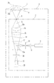
干渉計の概略構成を示す図1において、光学系ユニット2は、周囲の振動や空気流などの外乱が及ばないように防振機能を備えた筐体3に密封して収容されている。光学系ユニット2は筐体3内で図中上下方向に移動自在であり、基準レンズ及び被検レンズの曲率半径に応じて移動調節される。筐体3の天板には後述するレンズ支持装置5を設置するための基準ステージとなるマウント4が設けられ、本発明を適用したレンズ支持装置5を高精度に位置決めして保持する。なお、マウント4にXYステージ機能をもたせ、レンズ支持装置5を紙面と垂直な面内で移動調節できるようにしておくことが望ましい。
In FIG. 1 showing the schematic configuration of the interferometer, the
光学系ユニット2は一例としてフィゾー型干渉計で構成され、測定光として例えばHe−Neレーザ光を出力するレーザ発振器8を備えている。レーザ発振器8からの測定光は凸レンズからなる発散レンズ9によりピンホール10の位置で一旦集光された後、ビームスプリッタ12に入射し、ハーフミラー面12aで反射される。ハーフミラー面12aで反射された測定光は、鉛直な測定光軸Sにしたがって1/4波長板14を通り、コリメータレンズ15により平行光となって基準レンズ16に入射する。
The
基準レンズ16は上方に向けられた面が基準面16aとなり、測定光の反射面として用いられる。なお、基準レンズ16の下方に向けられた面からの反射光はノイズとなるため、この光入射面には反射防止コーティングが施される。基準面16aからの反射光は、コリメータレンズ15,1/4波長板14を経てビームスプリッタ12に入射する。そして、ハーフミラー面12aを透過した後、絞り18を通って結像レンズ19に入射し、その結像位置に設けられたCCDイメージセンサなどの撮像手段20に至る。
The
マウント4に装着されたレンズ支持装置5に、被検面24aを下向きにして被検レンズ24をセットしたとき、被検面24aの曲率中心が測定光軸S上にある基準面16aの曲率中心に合致していると、被検面24aで反射した測定光は基準面16aで反射した測定光と光学的に等価な光路にしたがって撮像手段20に達する。そして、これらの反射光は、基準面16aからの反射光が参照光、被検面24aからの反射光が物体光となって互いに干渉し、撮像手段20の受光面上で干渉縞が生じ、これを撮像して被検面24aの仕上がり度合いを評価することができる。
When the
この干渉計を適正に用いるには、上述のように基準面16aの曲率中心と被検面24aの曲率中心を一点Xで合致させることが前提となっている。基準レンズ16の方は、光学ユニット2に高精度に位置決めすることができるのに対し、被検レンズ24の方は測定ごとにレンズ支持装置5にセットされるため、レンズ支持装置5には高精度の調芯機能が要求される。被検面24aの曲率中心が紙面と垂直な面内で平行にずれている場合には、マウント4のXYステージの調整で対応が可能であり、また被検面24aの曲率中心が単に光軸S方向でずれている場合には光学ユニット2を昇降させることで対応できるが、被検面24aに倒れ、すなわち被検面24aが全体的に傾いてその曲率中心が測定光軸Sから外れている場合には、調整が非常に面倒で時間を要するものになる。
In order to use this interferometer appropriately, it is premised that the center of curvature of the
したがって、レンズ支持装置5には被検レンズ24の被検面24aが倒れなく測定光軸Sに正対させる機能が必要となる。この機能は、特許文献1で知られるように、鉛直方向に設定された測定光軸Sに関して好ましくは回転対称となる三点で被検面24aを支持し、被検レンズ24の自重による調芯作用を利用することによって簡便に達成できるが、前述したように、一般には被検レンズ24の外径が変わり、これに伴って被検面24aの外径が変わったときには対応できない。本発明のレンズ支持装置5は以下に述べるように、こうした問題にも簡便に対応することができるようになっている。
Therefore, the
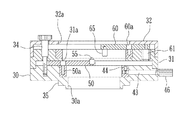
レンズ支持装置5は、図2、図3及び図4に示すようにそれぞれリング状になった下台座30(第1台座)及び上台座31(第2台座)と、カバープレート32とを有し、下台座30と上台座31とは三本のボルト34によって連結され、カバープレート32は上台座31にセットビス(図示省略)で固定される。各々の台座30,31及びカバープレート32にはそれぞれ円形の開口30a(第1開口),31a(第2開口),32aが形成され、上方から被検レンズ24をセットし、また下側からの測定光が被検面24aに達するようにしてある。図4に示すように、下台座30の底面側にはマウント4の受け側の形状に応じた位置決め用の段差35が高精度に切削加工されており、載置するだけでこのレンズ支持装置5は基準ステージとなるマウント4に高精度に位置決めされ、各々の開口30a,31aの中心軸Kは、測定光軸Sと一致する。
The
下台座30及び上台座31の底面側内周にそれぞれ段差が形成され、これらの段差によって回転リング40(第1回転リング),41(第2回転リング)が支持されている。回転リング40,41の外周面は下台座30,上台座31の内周面に接し、これらの回転リング40,41は中心軸Kの回りに回転自在である。回転リング40には調整用の操作軸43の先端がビス44で固定されるとともに、下台座30には操作軸43を中心軸Kの回りに回動させることができるように肉抜き部45が設けられている。したがって、操作軸43の他端側に設けたツマミ46を図3の矢印P方向に操作することによって、回転リング40を中心軸Kの回りに回動することができる。
Steps are formed on the inner periphery of the bottom surface of the
なお、ツマミ46を操作軸43に対して回転操作すると、ツマミ46が操作軸43のネジ条にしたがって軸方向に進退する。ツマミ46を締めつけてゆくとその前端面が下台座30の外周面に圧着されるから、その状態で操作軸43を調整位置で固定することができる。そして、ツマミ46を緩めてその固定を解除すると、操作軸43を中心軸Kの回りに回動操作することができるようになる。上台座31にも全く同様の操作軸が設けられ、ツマミ47の操作により回転リング41を中心軸Kの回りに回動することができ、またツマミ47自体を回転操作して任意の調整位置で固定しあるいは解除することができるようになっている。
Note that when the
回転リング40の上面には、中心軸Kに関して120°の回転対称となる位置にそれぞれレンズ支持アーム50が支軸50aにより揺動自在に軸着されている。レンズ支持アーム50の後端部にはカムフォロア51(第1突起)が固定され、下台座30に形成されたカム溝52(第1カム溝)に係合している。レンズ支持アーム50の先端部には、上方に突出したレンズ支持部材55が固定されている。レンズ支持部材55の上端は、被検レンズ24の被検面24aを受け止めたときに点で接触してほとんど摩擦抵抗が生じることがないようにボール形状となっており、これにより被検レンズ24は被検面24aが面内変位する方向でのみ移動自在に支持されることになる。
A
ツマミ46を緩めてから操作軸43を反時計方向に回動すると、回転リング40も同方向に回動する。なお、ボルト34を締めつけて回転リング40を下台座30と上台座31との間で挟持する構造にしたときには、操作軸43を回動する前にボルト34を緩め、回転リング40を所望の位置に回動させた後にボルト34を緊締する操作が必要となるが、レンズ支持アーム50を確実に所望の調整位置に固定するには、ボルト34に上記機能をもたせておくことが望ましい。
When the operating
回転リング40が反時計方向に回動すると、各々のレンズ支持アーム50の支軸50aが同方向に回動し、またカムフォロワ51とカム溝52との係合により、三本のレンズ支持アーム50は支軸50aを中心にして中心軸Kと直交する面内に沿って一斉に時計方向に揺動する。この結果、レンズ支持アーム50の先端部のレンズ支持部材55が中心軸Kに近づくように開口30a内に入り込んでゆく。また、回転リング40を時計方向に回動させたときには、三本のレンズ支持アーム50は同方向に回動しながら、レンズ支持部材55が中心軸Kから離れるように各々の支軸50aを中心に一斉に反時計方向に揺動する。したがって、レンズ支持アーム50が軸着された回転リング40、カムフォロア51及び下台座30に形成されたカム溝52は、三本のレンズ支持アーム50を一斉に揺動させる連動機構として作用する。
When the
同様に、上台座31に回転自在に組み込まれた回転リング41には、中心軸Kに関して120°の回転対称となる位置に支軸60aを介してレンズ押さえアーム60が揺動自在に軸着されている。レンズ押さえアーム60の後端部にはカムフォロア61(第2突起)が固定され、上台座31に形成されたカム溝62(第2カム溝)に係合している。レンズ押さえアーム60の先端部には、中心軸Kと平行に下向きに延びた円柱状のレンズ押さえ65が固定されている。
Similarly, a
これらのレンズ押さえアーム60が軸着された回転リング41、カムフォロア61及び上台座31に形成されたカム溝62は、三本のレンズ押さえアーム60を一斉に揺動させる連動機構として作用し、ツマミ47を操作して回転リング41を反時計方向に回動すると、レンズ押さえアーム60の先端部のレンズ押さえ部材65が中心軸Kに直交する面内に沿って中心軸Kに近づくように開口31a内に一斉に入り込んでゆく。もちろん、各々のレンズ押さえ部材65は常に中心軸Kから等距離の位置を保つ。
The
これらのレンズ支持アーム50及びレンズ押さえアーム60を揺動させることにより、図5に示すように外径に応じて被検レンズ24を支持することができる。レンズ支持部材55はボール形状をした突端により、光軸Sに関して120°の回転対称となる位置で被検面24をほとんど摩擦抵抗がない点接触で支持する。レンズ支持部材55には被検レンズ24の自重が均等に加わるため、たとえ被検レンズ24に倒れがあった場合でも、自動的に曲率中心が光軸S上にくるように位置決めされる。なお、被検面24aが球面であれば凸面,凹面のいずれでも被検面24aが測定光軸Sに正対するように被検レンズ24の位置決めを行うことが可能である。また、ツマミ46の調整位置とレンズ支持部材55の位置とは一対一に対応しているから、図2に示すように、ツマミ46の近傍に指標46aを付しておけば、この指標46aを目安にして被検面24の外径に応じて適切な位置にレンズ支持部材55を移動させることができ、操作性を高めることができる。もちろん、他方のツマミ47に対しても同様の指標を設けておくのが好ましい。
By swinging the
さらに、被検レンズ24を三点で支持し、しかも被検面24の評価対象エリアを広くするには、被検レンズ24の外周面に近い位置で被検レンズ24を支持するのが有利であるが、被検レンズ24をレンズ支持部材55の上に載置するときの位置ずれ量が大きいときには、被検レンズ24がレンズ支持部材55から滑り落ちることが懸念される。こうした場合であっても、レンズ押さえアーム60をあらかじめ適切な位置にセットしておくと、仮に被検レンズ24がレンズ支持部材55上を滑ってずり落ちそうになっても、少なくとも2つのレンズ押さえ部材65が被検レンズ24の外周面を受け止めることになるから、不用意に被検レンズ24を落下させるといった事故を確実に防ぐことができる。なお、このように被検レンズ24がレンズ支持部材55上でずれたとしても、レンズ支持部材55が被検面24aを三点で支持している限りでは、被検面24aの曲率中心は図1の点Xからずれることはないので、そのままで被検面24aの測定を行うことができる。
Further, in order to support the
上述のように、被検レンズ24の自重はレンズ支持部材55を介してレンズ支持アーム50の先端部に加わることになるが、レンズ支持アーム50はその後端部ではなく中間部が回転リング40に軸着されていること、また揺動させるためのカムスロットがレンズ支持アーム50自体に設けられていないという構成上の特徴から十分な強度を確保することができる。さらに、レンズ支持アーム50の上面は上台座31の底面で規制されているから上下方向に移動したり傾いたりすることがなく、レンズ支持アーム50を剛性の高い素材で作製しておけば、被検レンズ24の自重で先端側が撓むこともなく、被検レンズ24を測定光軸Sと直交する略同一の平面内で正しく支持することができる。
As described above, the weight of the
以上、図示した実施形態にしたがって説明してきたが、例えばレンズ押さえアーム60を変位させる操作軸についてはツマミ47を回転操作して上台座31に固定できるようにし、レンズ支持アーム50を変位させる操作軸43についてはツマミ46の回転操作による固定機能を省略してフリクションなどで調節位置に保持されるようにしてもよい。この場合、レンズ支持部材55は必ずレンズ押さえ部材65よりも内側に位置することになるから、レンズ支持アーム50の一部をレンズ押さえアーム60あるいはレンズ押さえ部材65に内側から当接させて位置決めすることも可能である。さらに、レンズ支持アーム50あるいはレンズ押さえアーム60は必ずしも三本同時に連動させなくてもよく、個別に移動調節させるようにしてもよい。
As described above, the operation shaft for displacing the
また、上記実施形態では、レンズ支持アーム50あるいはレンズ押さえアーム60を中心軸Kに関して120°の回転対称となる位置に組み付け、レンズ支持部材55やレンズ押さえ部材65を中心軸Kに関して120°の回転対称となるように、しかも中心軸Kからの距離が互いに等しくなるように移動させているが、レンズ支持部材55やレンズ押さえ部材65が中心軸Kと直交する面内に沿って開口30a,31aに出入りする構成であれば、レンズ支持アーム50あるいはレンズ押さえアーム60を必ずしも回転対称となるようにそれぞれの台座30,31に組み付けなくてもよく、レンズ支持部材55やレンズ押さえ部材65も中心軸Kに関して回転対称あるいは中心軸Kから常に等距離でなくてもよい。
In the above embodiment, the
さらに、レンズ押さえアーム60を省略し、レンズ支持アーム50の先端側にレンズ押さえ部材65を設けることも可能である。この場合には、中心軸Kに対してレンズ押さえ部材65をレンズ支持部材55の外側に配置すればよい。そして、それぞれのレンズ押さえ部材65とそれぞれのレンズ支持部材55との間隔を調整できるようにしておけば、被検面24aの外周縁と被検レンズ24の外周面との間隔が変わっても簡便に対応することが可能となる。
Further, the
2 光学ユニット
4 マウント
5 レンズ支持装置
30 下台座
31 上台座
32 カバープレート
40,41 回転リング
43 操作軸
50 レンズ支持アーム
51 カムフォロア
52 カム溝
55 レンズ支持部材
60 レンズ押さえアーム
65 レンズ押さえ部材
2
Claims (3)
干渉計の基準ステージ上に設置され前記測定光を通過させる第1開口が形成された第1台座と、
前記第1台座に変位自在に組み込まれ、その変位に伴って先端部が前記光軸と略直交する面内で前記第1開口に出入りする三本のレンズ支持アームと、
前記レンズ支持アームの先端部に各々設けられ、レンズ支持アームの上方から載置される被検レンズの被検面を面内変位自在に受け止めるレンズ支持部材と、
干渉計の基準ステージ上に設置され前記測定光を通過させる第2開口が形成され、前記第1台座上に配置される第2台座と、
前記第2台座に変位自在に組み込まれ、かつ前記レンズ支持アームよりも上方で先端部が前記光軸と略直交する面内で前記第2開口に出入り自在な三本のレンズ押さえアームと、
前記レンズ押さえアームの各々の先端部に前記光軸と平行に下方に延びるように突設され、前記レンズ支持部で被検面が支持された被検レンズの外周面を受け止める外周押さえ部材とを備えたことを特徴とする干渉計の被検レンズ支持装置。 It is used in an interferometer that irradiates both the reference surface and the test surface of the test lens with measurement light, and measures interference fringes caused by interference of reflected light from the respective surfaces, with respect to the optical axis of the measurement light. In the test lens support device of the interferometer that supports the test lens so that the test surface is facing directly,
A first pedestal installed on a reference stage of an interferometer and having a first opening through which the measurement light passes;
Three lens support arms that are incorporated in the first pedestal so as to be displaceable, and with the displacement, the front end portion enters and exits the first opening in a plane substantially orthogonal to the optical axis;
A lens support member provided at each of the front end portions of the lens support arm and receiving the test surface of the test lens placed from above the lens support arm so as to be freely displaceable in a plane;
A second pedestal installed on the reference stage of the interferometer, formed with a second opening through which the measurement light passes, and disposed on the first pedestal;
Three lens pressing arms that are movably incorporated in the second pedestal and that can be freely moved into and out of the second opening in a plane that is above the lens support arm and that is substantially perpendicular to the optical axis;
An outer periphery pressing member that protrudes from each tip end of the lens pressing arm so as to extend downward in parallel with the optical axis and receives the outer peripheral surface of the lens to be tested supported by the lens support portion. A test lens support device for an interferometer, comprising:
前記第1連動機構は、レンズ支持アームの後端に設けられ前記第1台座に形成された第1カム溝に係合する第1突起と、レンズ支持アームの中間部を回転自在に支持するとともに前記光軸を中心に回転自在に前記第1台座に組み付けられた第1回転リングとからなり、前記第1回転リングを回転させることにより各々のレンズ支持アームが変位して前記レンズ支持部材が前記第1開口内に出入りすることを特徴とする請求項1記載の干渉計の被検レンズ支持装置。 Lens support arm of the three, as well as assembled to the first pedestal in a position where a rotational symmetry with respect to the optical axis, the distance is equal from the optical axis by displacing the lens support arm of the three at the same time A first interlocking mechanism for moving the lens support member into and out of the first opening all at once ,
The first interlocking mechanism rotatably supports a first protrusion provided at a rear end of the lens support arm and engaged with a first cam groove formed on the first base, and an intermediate portion of the lens support arm. A first rotating ring assembled to the first base so as to be rotatable about the optical axis. By rotating the first rotating ring, each lens supporting arm is displaced, and the lens supporting member is 2. The interferometer lens-supporting device according to claim 1, wherein the lens enters and exits the first opening .
前記第二の連動機構は、前記レンズ押さえアームの後端に設けられ前記第2台座に形成された第2カム溝に係合する第2突起と、レンズ押さえアームの中間部を回転自在に支持するとともに前記光軸を中心に回転自在に前記第2台座に組み付けられた第2回転リングとからなり、前記第2回転リングを回転させることにより各々のレンズ押さえアームが変位して前記レンズ押さえ部材が前記第2開口内に出入りすることを特徴とする請求項1または2記載の干渉計の被検レンズ支持装置。 The three lens pressing arms are assembled to the second pedestal at a position that is rotationally symmetric with respect to the optical axis, and these three lens pressing arms are simultaneously displaced so that the distance from the optical axis becomes equal. A second interlocking mechanism that allows the outer periphery pressing member to enter and exit from the second opening all at once,
The second interlocking mechanism rotatably supports a second protrusion provided at a rear end of the lens pressing arm and engaging with a second cam groove formed in the second pedestal, and an intermediate portion of the lens pressing arm. And a second rotating ring assembled to the second pedestal so as to be rotatable about the optical axis, and by rotating the second rotating ring, each lens pressing arm is displaced to displace the lens pressing member. The test lens supporting device for an interferometer according to claim 1, wherein the lens enters and exits into the second opening .
Priority Applications (2)
| Application Number | Priority Date | Filing Date | Title |
|---|---|---|---|
| JP2005031840A JP4659476B2 (en) | 2005-02-08 | 2005-02-08 | Interferometer lens support device |
| CNB2006100066803A CN100510674C (en) | 2005-02-08 | 2006-02-08 | Supporting device of measured lens of interferometer |
Applications Claiming Priority (1)
| Application Number | Priority Date | Filing Date | Title |
|---|---|---|---|
| JP2005031840A JP4659476B2 (en) | 2005-02-08 | 2005-02-08 | Interferometer lens support device |
Publications (3)
| Publication Number | Publication Date |
|---|---|
| JP2006220440A JP2006220440A (en) | 2006-08-24 |
| JP2006220440A5 JP2006220440A5 (en) | 2007-12-27 |
| JP4659476B2 true JP4659476B2 (en) | 2011-03-30 |
Family
ID=36918701
Family Applications (1)
| Application Number | Title | Priority Date | Filing Date |
|---|---|---|---|
| JP2005031840A Expired - Fee Related JP4659476B2 (en) | 2005-02-08 | 2005-02-08 | Interferometer lens support device |
Country Status (2)
| Country | Link |
|---|---|
| JP (1) | JP4659476B2 (en) |
| CN (1) | CN100510674C (en) |
Families Citing this family (13)
| Publication number | Priority date | Publication date | Assignee | Title |
|---|---|---|---|---|
| CN101393073B (en) * | 2007-09-17 | 2011-06-22 | 鸿富锦精密工业(深圳)有限公司 | Eccentric measuring set and measuring instruments |
| TWI409431B (en) * | 2007-10-19 | 2013-09-21 | Hon Hai Prec Ind Co Ltd | Device for measuring centering error and instrument including same |
| KR100956230B1 (en) * | 2008-08-07 | 2010-05-04 | 삼성전기주식회사 | Apparatus for inspecting lens and control method for the same |
| EP2758749B1 (en) * | 2012-12-04 | 2016-10-12 | Essilor International (Compagnie Générale D'Optique) | Apparatus and method for performing a reflection measurement on an eyeglass |
| JP6260141B2 (en) * | 2013-08-20 | 2018-01-17 | 株式会社ニコン | Accessory coupling device |
| CN103499318B (en) * | 2013-10-21 | 2015-12-02 | 中国科学院光电技术研究所 | A kind of assay method of dead weight deflection of optical element |
| CN103528796A (en) * | 2013-10-23 | 2014-01-22 | 江苏双仪光学器材有限公司 | Interferometer fixture |
| CN103558013B (en) * | 2013-11-21 | 2015-11-18 | 苏州大学 | A kind of detection method of Rotational Symmetry free-form surface lens |
| JP6492702B2 (en) * | 2015-01-30 | 2019-04-03 | コニカミノルタ株式会社 | Optical element measuring apparatus and measuring method |
| CN109443280A (en) * | 2018-11-30 | 2019-03-08 | 松林光电科技(湖北)有限公司 | A kind of lens detection device |
| CN109798840A (en) * | 2019-02-26 | 2019-05-24 | 中国科学院光电技术研究所 | The detection device of lens face shape deflection is detected in stitching interferometer instrument |
| CN110132167A (en) * | 2019-05-06 | 2019-08-16 | 苏州慧利仪器有限责任公司 | Optical flat bearing device and laser interference detection device |
| JP7310760B2 (en) * | 2020-08-31 | 2023-07-19 | いすゞ自動車株式会社 | transport pallet |
Citations (5)
| Publication number | Priority date | Publication date | Assignee | Title |
|---|---|---|---|---|
| JPS5865504U (en) * | 1981-10-28 | 1983-05-04 | オリンパス光学工業株式会社 | Lens thickness measuring machine |
| JPH0911073A (en) * | 1995-06-22 | 1997-01-14 | Canon Inc | General purpose positioning clamp device |
| JPH0921722A (en) * | 1995-07-04 | 1997-01-21 | Olympus Optical Co Ltd | Lens fixture |
| JPH09290340A (en) * | 1996-04-25 | 1997-11-11 | Nikon Corp | Gentering device for circular unit |
| JP2001147179A (en) * | 1999-11-24 | 2001-05-29 | Olympus Optical Co Ltd | Inspected lens support mechanism for interferometer |
Family Cites Families (1)
| Publication number | Priority date | Publication date | Assignee | Title |
|---|---|---|---|---|
| US4541717A (en) * | 1983-12-08 | 1985-09-17 | Fuji Photo Optical Co., Ltd. | Attraction holding device |
-
2005
- 2005-02-08 JP JP2005031840A patent/JP4659476B2/en not_active Expired - Fee Related
-
2006
- 2006-02-08 CN CNB2006100066803A patent/CN100510674C/en not_active Expired - Fee Related
Patent Citations (5)
| Publication number | Priority date | Publication date | Assignee | Title |
|---|---|---|---|---|
| JPS5865504U (en) * | 1981-10-28 | 1983-05-04 | オリンパス光学工業株式会社 | Lens thickness measuring machine |
| JPH0911073A (en) * | 1995-06-22 | 1997-01-14 | Canon Inc | General purpose positioning clamp device |
| JPH0921722A (en) * | 1995-07-04 | 1997-01-21 | Olympus Optical Co Ltd | Lens fixture |
| JPH09290340A (en) * | 1996-04-25 | 1997-11-11 | Nikon Corp | Gentering device for circular unit |
| JP2001147179A (en) * | 1999-11-24 | 2001-05-29 | Olympus Optical Co Ltd | Inspected lens support mechanism for interferometer |
Also Published As
| Publication number | Publication date |
|---|---|
| CN100510674C (en) | 2009-07-08 |
| JP2006220440A (en) | 2006-08-24 |
| CN1818596A (en) | 2006-08-16 |
Similar Documents
| Publication | Publication Date | Title |
|---|---|---|
| JP4659476B2 (en) | Interferometer lens support device | |
| US7492468B2 (en) | Free-form optical surface measuring apparatus and method | |
| JP2005127914A (en) | Mounting stand for lens to be inspected of interferometer system | |
| US6515750B1 (en) | Interferometric system for and method of testing and characterizing micro-optic components | |
| US2880644A (en) | Alignement interferometer | |
| US5546186A (en) | Apparatus for holographic interferometry suitable for inspection of cylindrical optical surfaces | |
| KR101749818B1 (en) | Experiment device of reflecting telescope | |
| JP3079900B2 (en) | Hologram interferometer for measuring cylindrical optical elements | |
| JP3590193B2 (en) | Interferometer device | |
| JP2006267085A (en) | Instrument and method for measuring eccentricity of aspherical lens | |
| JP3282296B2 (en) | Hologram interferometer for measuring cylindrical optical elements | |
| JP2005241596A5 (en) | ||
| JP3237317B2 (en) | Hologram interferometer | |
| JP2006292458A (en) | Method and device for inspecting spherical eccentricity of inclined spherically polished ferrule | |
| JP3372322B2 (en) | Aspherical lens eccentricity measuring apparatus and aspherical lens eccentricity measuring method | |
| JP2005164305A (en) | Analyte mount for interferometer apparatus | |
| JP3174318B2 (en) | Lens eccentricity measuring device | |
| JPH11237305A (en) | Detecting apparatus for deviation of optical axis | |
| US4496242A (en) | Apparatus for positioning a contact lens under a radiuscope | |
| JP2005069697A (en) | Ferrule measuring method by microinterferometer apparatus | |
| JP4061175B2 (en) | Interferometer device | |
| RU20378U1 (en) | INTERFEROMETER FOR CONTROL OF OPTICAL DETAILS (OPTIONS) | |
| JPH09269277A (en) | Lens eccentricity measuring device | |
| JP2006090950A (en) | Measuring system of inclination of surface to be tested | |
| JPH11211611A (en) | Eccentricity measuring apparatus |
Legal Events
| Date | Code | Title | Description |
|---|---|---|---|
| A521 | Written amendment |
Free format text: JAPANESE INTERMEDIATE CODE: A523 Effective date: 20071113 |
|
| A621 | Written request for application examination |
Free format text: JAPANESE INTERMEDIATE CODE: A621 Effective date: 20071113 |
|
| A977 | Report on retrieval |
Free format text: JAPANESE INTERMEDIATE CODE: A971007 Effective date: 20100402 |
|
| A711 | Notification of change in applicant |
Free format text: JAPANESE INTERMEDIATE CODE: A711 Effective date: 20100617 |
|
| A131 | Notification of reasons for refusal |
Free format text: JAPANESE INTERMEDIATE CODE: A131 Effective date: 20100908 |
|
| A521 | Written amendment |
Free format text: JAPANESE INTERMEDIATE CODE: A523 Effective date: 20101105 |
|
| TRDD | Decision of grant or rejection written | ||
| A01 | Written decision to grant a patent or to grant a registration (utility model) |
Free format text: JAPANESE INTERMEDIATE CODE: A01 Effective date: 20101201 |
|
| A01 | Written decision to grant a patent or to grant a registration (utility model) |
Free format text: JAPANESE INTERMEDIATE CODE: A01 |
|
| A61 | First payment of annual fees (during grant procedure) |
Free format text: JAPANESE INTERMEDIATE CODE: A61 Effective date: 20101227 |
|
| FPAY | Renewal fee payment (event date is renewal date of database) |
Free format text: PAYMENT UNTIL: 20140107 Year of fee payment: 3 |
|
| R150 | Certificate of patent or registration of utility model |
Free format text: JAPANESE INTERMEDIATE CODE: R150 |
|
| LAPS | Cancellation because of no payment of annual fees |