JP4659231B2 - Image forming apparatus, process unit, and toner cartridge - Google Patents
Image forming apparatus, process unit, and toner cartridge Download PDFInfo
- Publication number
- JP4659231B2 JP4659231B2 JP2001045083A JP2001045083A JP4659231B2 JP 4659231 B2 JP4659231 B2 JP 4659231B2 JP 2001045083 A JP2001045083 A JP 2001045083A JP 2001045083 A JP2001045083 A JP 2001045083A JP 4659231 B2 JP4659231 B2 JP 4659231B2
- Authority
- JP
- Japan
- Prior art keywords
- main body
- toner
- hole
- image
- actuator
- Prior art date
- Legal status (The legal status is an assumption and is not a legal conclusion. Google has not performed a legal analysis and makes no representation as to the accuracy of the status listed.)
- Expired - Fee Related
Links
Images


Description
【0001】
【発明の属する技術分野】
本発明は、電子写真プロセスにより画像を形成する画像形成装置及びこの装置に設けられるプロセスユニット並びにトナーカートリッジに関する。
【0002】
【従来の技術】
レーザプリンタやレーザファクシミリ等の画像形成装置は電子写真プロセスにより画像を形成するようになっている。電子写真プロセスによる画像形成は、表面に感光層を設けた感光体ドラムを備え、この感光体ドラムの表面を帯電手段で均一に帯電した後、露光手段により露光して静電潜像を形成し、この静電潜像を現像手段からのトナーにより現像してトナー像として顕像化し、この顕像化したトナー像を転写手段により記録媒体に転写することで行われる。
【0003】
このような画像形成装置では、感光体ドラムや現像手段をユニット化してプロセスユニットとし、このプロセスユニットを装置本体に対して挿脱自在にすると共に現像手段にトナーを補給するトナーカートリッジも装置本体に対して挿脱自在にしたものが知られている。すなわち、プロセスユニットやトナーカートリッジは横に細長い構成になっていて装置本体の側部に設けた挿入部にそれぞれ長手方向から先ずプロセスユニットを挿入して位置決めし、続いてトナーカートリッジを挿入して位置決めするようになっている。
【0004】
そして、プロセスユニットやトナーカートリッジの装置本体に対する位置決めは、プロセスユニットやトナーカートリッジの挿入側先端に設けた位置決め用の突起部を挿入時に装置本体のフレームに設けた孔にそれぞれ嵌入することで行っている。
【0005】
図7はトナーカートリッジ1を装置本体に対して図中矢印方向に挿入している途中の様子を示し、図8はトナーカートリッジ1を装置本体に挿入し終えたときの様子を示している。トナーカートリッジ1は長手方向から挿入され、その挿入側先端には位置決め用の突起部2が設けられている。また、トナーカートリッジ1の内部にはトナーをプロセスユニットの現像手段に補給するためのスクリュー機構があり、このスクリュー機構へ動力を伝達させるのに必要な連結機構3も挿入側先端に設けられている。
【0006】
また、装置本体のフレーム4には、突起部2を嵌入する孔5、トナーカートリッジ1の連結機構3に連結して動力を伝達する動力伝達機構6及びトナーカートリッジ1の挿着を検出するスイッチ7が設けられている。
【0007】
そして、トナーカートリッジ1が所定の位置まで挿入されると、図8に示すように、突起部2が孔5に嵌入して位置決めが行われると共に連結機構3が動力伝達機構6に連結され、さらに、トナーカートリッジ1の先端部に設けた別の突起部8で突出していたスイッチ7のアクチュエータ9を押圧し、スイッチ7はトナーカートリッジ1が挿入されたことを検出するようになっていた。
【0008】
【発明が解決しようとする課題】
しかし、このようにスイッチ7のアクチュエータ9がトナーカートリッジ1の挿入側に突出していたのでは、トナーカートリッジの挿入時にトナーカートリッジの先端部がスイッチのアクチュエータに対して斜めに当接したり、先端部の指定部分以外の部分が当接したりするとアクチュエータが変形したり、破損したりする虞があった。また、トナーカートリッジが離脱されているときにオペレータの手などが挿入されてアクチュエータにぶつかることがあるとアクチュエータが変形したり、破損したりする虞があった。また、トナーカートリッジの先端部には位置決め用の突起部2とは別にスイッチ7のアクチュエータを押圧するための突起部8を設けているため、先端部の形状が多数の突起によって複雑化するという問題があった。
【0009】
また、プロセスユニットの場合もトナーカートリッジと同様にプロセスユニットの挿入を検出するスイッチを設けている場合には、このスイッチのアクチュエータがプロセスユニットの挿入側に突出しておりアクチュエータが変形したり、破損したりするおそれがあり、また、先端部の形状が多数の突起によって複雑化し、取り扱いも面倒になるという問題があった。
【0010】
そこで本発明は、プロセスユニットやトナーカートリッジの挿入を検出するスイッチのアクチュエータが変形したり、破損したりする虞が無く、しかも、プロセスユニットやトナーカートリッジの挿入先端部の形状を単純化でき、取り扱いも容易となる画像形成装置及びこの装置に設けられるプロセスユニット並びにトナーカートリッジを提供する。
【0011】
【課題を解決するための手段】
請求項1記載の発明は、表面に感光層を設けた感光体ドラムを備え、この感光体ドラムの表面を帯電手段で均一に帯電した後、露光手段により露光して静電潜像を形成し、この静電潜像を現像手段からのトナーにより現像してトナー像として顕像化し、この顕像化したトナー像を転写手段により記録媒体に転写する電子写真プロセスにより画像を形成する画像形成装置であり、感光体ドラム及び現像手段の一方又は両方を有するプロセスユニットを装置本体に対して挿脱自在にすると共に現像手段にトナーを補給するトナーカートリッジを装置本体に対して挿脱自在にし、プロセスユニット及びトナーカートリッジの一方又は両方の挿入側先端に位置決め用の突起部を設け、プロセスユニット及びトナーカートリッジの一方又は両方の挿入時に突起部が装置本体のフレームに設けた孔に嵌入して位置決めを行うものにおいて、
プロセスユニット及びトナーカートリッジの一方又は両方に設けた突起部が挿入される孔の一方又は両方の近傍の、フレームに設けた孔から突起部が突出する突出側にプロセスユニット及びトナーカートリッジの一方又は両方の装置本体への挿着をアクチュエータが押圧されることで検出するスイッチを設け、このスイッチのアクチュエータが突起部の先端で押圧されるようにアクチュエータを孔の上に延在させ、プロセスユニット及びトナーカートリッジの一方又は両方に内部機構に動力を伝達するのに必要な連結機構を備え、装置本体に連結機構に連結して動力を伝達する動力伝達機構を備え、突起部が孔に挿入して位置決めと、スイッチのアクチュエータに対する押圧が行われるとともに、連結機構が動力伝達機構に連結されるものである。
【0012】
請求項2記載の発明は、表面に感光層を設けた感光体ドラムを備え、この感光体ドラムの表面を帯電手段で均一に帯電した後、露光手段により露光して静電潜像を形成し、この静電潜像を現像手段からのトナーにより現像してトナー像として顕像化し、この顕像化したトナー像を転写手段により記録媒体に転写する電子写真プロセスにより画像を形成する画像形成装置であり、感光体ドラム及び現像手段の一方又は両方を有するプロセスユニットを装置本体に対して挿脱自在にし、プロセスユニットの挿入側先端に位置決め用の突起部を設け、プロセスユニットの挿入時に突起部が装置本体のフレームに設けた孔に嵌入して位置決めを行うものにおいて、
プロセスユニットに設けた突起部が挿入される孔の近傍の、フレームに設けた孔から突起部が突出する突出側にプロセスユニットの装置本体への挿着をアクチュエータが押圧されることで検出するスイッチを設け、このスイッチのアクチュエータが突起部の先端で押圧されるようにアクチュエータを孔の上に延在させ、プロセスユニットに内部機構に動力を伝達するのに必要な連結機構を備え、装置本体に連結機構に連結して動力を伝達する動力伝達機構を備え、突起部が孔に挿入して位置決めと、スイッチのアクチュエータに対する押圧が行われるとともに、連結機構が動力伝達機構に連結されるものである。
【0013】
請求項3記載の発明は、表面に感光層を設けた感光体ドラムを備え、この感光体ドラムの表面を帯電手段で均一に帯電した後、露光手段により露光して静電潜像を形成し、この静電潜像を現像手段からのトナーにより現像してトナー像として顕像化し、この顕像化したトナー像を転写手段により記録媒体に転写する電子写真プロセスにより画像を形成する画像形成装置であり、現像手段にトナーを補給するトナーカートリッジを装置本体に対して挿脱自在にし、トナーカートリッジの挿入側先端に位置決め用の突起部を設け、トナーカートリッジの挿入時に突起部が装置本体のフレームに設けた孔に嵌入して位置決めを行うものにおいて、
トナーカートリッジに設けた突起部が挿入される孔の近傍の、フレームに設けた孔から突起部が突出する突出側にトナーカートリッジの装置本体への挿着をアクチュエータが押圧されることで検出するスイッチを設け、このスイッチのアクチュエータが突起部の先端で押圧されるようにアクチュエータを孔の上に延在させ、トナーカートリッジに内部機構に動力を伝達するのに必要な連結機構を備え、装置本体に連結機構に連結して動力を伝達する動力伝達機構を備え、突起部が孔に挿入して位置決めと、スイッチのアクチュエータに対する押圧が行われるとともに、連結機構が前記動力伝達機構に連結されるものである。
【0014】
【発明の実施の形態】
以下、本発明の実施の形態を、図面を参照して説明する。
図1は画像形成装置の外観を示す斜視図、図2は装置内部の概略構成を示す断面図である。
【0015】
この画像形成装置は、装置本体11の内底部に設けた給紙カセット12に積層した記録紙Pを給紙ローラ13で一枚ずつ搬送路に送り出し、搬送ローラ14によって上側へ向けて搬送し、排紙ローラ15から装置本体11の中断部に設けた排紙受部16の排出するようになっている。
【0016】
搬送路の途中には電子写真プロセス機構が配置されている。この電子写真プロセス機構は、表面に感光層を設け、図中矢印で示す方向に回転する感光体ドラム17を備え、この感光体ドラム17の周囲に、この感光体ドラム17の表面を均一に帯電するコロナ帯電器などの帯電手段18、この帯電手段18で均一に帯電した感光層を露光して静電潜像を形成するレーザユニットなどの露光手段19、この露光手段19による露光によって形成された静電潜像をトナーを使用して現像し顕像化する現像手段20、この現像手段20にて顕像化したトナー像を前記記録紙Pに転写するコロナ転写器などの転写手段21、この転写手段21により記録紙Pに帯電した電荷を消去する除電手段22により構成している。
【0017】
前記現像手段20はトナーを収容したトナー収容部23やこのトナー収容部23のトナーを前記感光体ドラム17に送り出す現像ローラ24を備えている。
前記感光体ドラム17、帯電手段18、現像手段20はプロセスユニット25を構成し、このプロセスユニット25は装置本体11に対して挿脱自在になっている。なお、プロセスユニットとしては、前記感光体ドラム17のみのものであっても、現像手段20のものものであっても、これらに帯電手段18を含むものであってもよい。
【0018】
前記転写手段21にてトナー像が転写され、さらに、前記除電手段22にて電荷が消去された記録紙Pは、搬送路に設けられた熱定着器29によって加熱定着された後、前記排紙ローラ15によって排紙受部16に排出されるようになる。
【0019】
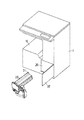
図3は前記プロセスユニット25の外観を示す斜視図で、このプロセスユニット25は横に細長い形状を為し、装置本体11の側面に設けた出し入れ口26にその長手方向から挿入するようになっている。なお、前記出し入れ口26には開閉自在な扉27が設けられている。
【0020】
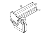
図4は前記プロセスユニット25が装置本体11に挿入された後、同じく前記出し入れ口26から挿入されるトナーカートリッジ28を示す斜視図で、このトナーカートリッジ28も横に細長い形状を為し、図1に示すように、前記出し入れ口26にその長手方向から挿入するようになっている。そして、この挿入において、前記トナーカートリッジ28の先端部はプロセスユニット25の外ケースに当接しながらスライドして挿入される。
【0021】
前記プロセスユニット25における現像手段20のトナー収容部23の位置には補給されるトナーを受け入れるトナー受入口があり、トナー受入口にはスライドシャッターが付いている。また、前記トナーカートリッジ28には前記トナー収容部23にトナーを補給するためのトナー吐出口があり、このトナー吐出口にはスライドシャッターが付いている。
【0022】
そして、前記プロセスユニット25が挿入された状態で前記トナーカートリッジ28を挿入すると、プロセスユニット25のスライドシャッターとトナーカートリッジのスライドシャッターが係合してそれぞれ開放され、トナーカートリッジ28が所定の位置まで挿入されると、プロセスユニット25のトナー受入口とトナーカートリッジ28のトナー吐出口が開放状態で対向し合うようになる。
【0023】
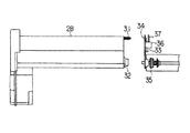
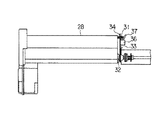
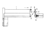
図5は前記トナーカートリッジ28を装置本体11に対して図中矢印方向に挿入している途中の様子を示し、図6は前記トナーカートリッジ28を装置本体11に挿入し終えたときの様子を示している。
【0024】
前記トナーカートリッジ28の挿入側先端には位置決め用の突起部31が設けられている。また、前記トナーカートリッジ28の内部にはトナーをトナー吐出口に送り出すためのスクリュー機構があり、このスクリュー機構へ動力を伝達させるのに必要な連結機構32も挿入側先端に設けられている。
【0025】
また、前記装置本体11の出し入れ口26の奥に位置するフレーム33には、前記突起部31を嵌入する孔34、前記トナーカートリッジ28の連結機構32に連結して動力を伝達する動力伝達機構35が設けられている。また、前記孔34の近傍には、前記突起部31がその孔34に挿入されたときにその突起部31が突出する側の前記フレーム33上にトナーカートリッジ28の装置本体11への挿着を検出するスイッチ36を設け、このスイッチ36を駆動するアクチュエータ37を孔34に挿入される突起部31の先端で押圧されるように孔34の上に延出させている。
【0026】
従って、前記トナーカートリッジ28を装置本体11に対して所定の位置まで挿入すると、図6に示すように、突起部31が孔34に嵌入して位置決めが行われると共に連結機構32が動力伝達機構35に連結される。そして、孔34に嵌入した突起部31の先端がスイッチ36のアクチュエータ37を押圧する。これにより、スイッチ36はトナーカートリッジ28が挿入されたことを検出する殊になる。
【0027】
このように、スイッチ36のアクチュエータ37はフレーム33からトナーカートリッジ28の挿入側に突出していないので、トナーカートリッジ28の挿入時にその先端部によってアクチュエータ37が変形したり、破損したりする虞は全く無い。また、人の手がトナーカートリッジ28及びプロセスユニット25の挿入部に入っているときにその手がぶつかってアクチュエータ37が変形したり、破損したりする虞も全く無い。
【0028】
また、トナーカートリッジ28の先端部に設けた位置決め用の突起部31がトナーカートリッジ28の位置決めとスイッチ36のアクチュエータ37の押圧とを兼用しているので、トナーカートリッジ28の先端部にはスイッチ36のアクチュエータ37を押圧するための突起部を別途設ける必要はなく、トナーカートリッジ28の先端部の形状を単純化でき、取り扱いも容易となる。
【0029】
なお、この実施の形態では、位置決め及び挿入検出をトナーカートリッジについて行う場合を例として述べたが、これはプロセスユニットの位置決め及び挿入検出にも適用できるものである。そして、この発明の位置決め及び挿入検出は、トナーカートリッジ及びプロセスユニットのいずれか一方に行うものであっても、また、両方に行うものであってもよい。
【0030】
また、この実施の形態は、この発明をトナーカートリッジ及びプロセスユニットの両方を有する画像形成装置に適用したものについて述べたが必ずしもこれに限定するものではなく、トナーカートリッジのみを有する画像形成装置やプロセスユニットのみを有する画像形成装置にも適用できるものである。
【0031】
【発明の効果】
以上詳述したように本発明によれば、プロセスユニットやトナーカートリッジの挿入を検出するスイッチのアクチュエータが変形したり、破損したりする虞が無く、しかも、プロセスユニットやトナーカートリッジの挿入先端部の形状を単純化でき、取り扱いも容易となる画像形成装置及びこの装置に設けられるプロセスユニット並びにトナーカートリッジを提供できる。
【図面の簡単な説明】
【図1】本発明の実施の形態に係る画像形成装置の外観を示す斜視図。
【図2】同実施の形態における装置内部の概略構成を示す断面図。
【図3】同実施の形態におけるプロセスユニットの外観を示す斜視図。
【図4】同実施の形態におけるトナーカートリッジの外観を示す斜視図。
【図5】同実施の形態においてトナーカートリッジを装置本体に挿入している途中の様子を示す図。
【図6】同実施の形態においてトナーカートリッジを装置本体に挿入し終えたときの様子を示す図。
【図7】従来の画像形成装置においてトナーカートリッジを装置本体に挿入している途中の様子を示す図。
【図8】従来の画像形成装置においてトナーカートリッジを装置本体に挿入し終えたときの様子を示す図。
【符号の説明】
11…装置本体
17…感光体ドラム
18…帯電手段
19…露光手段
20…現像手段
21…転写手段
25…プロセスユニット
28…トナーカートリッジ
31…突起部
33…フレーム
34…孔
36…スイッチ
37…アクチュエータ[0001]
BACKGROUND OF THE INVENTION
The present invention relates to an image forming apparatus that forms an image by an electrophotographic process , a process unit provided in the apparatus, and a toner cartridge .
[0002]
[Prior art]
An image forming apparatus such as a laser printer or a laser facsimile forms an image by an electrophotographic process. Image formation by an electrophotographic process includes a photosensitive drum provided with a photosensitive layer on the surface. The surface of the photosensitive drum is uniformly charged by a charging unit, and then exposed by an exposing unit to form an electrostatic latent image. The electrostatic latent image is developed with toner from the developing means to be visualized as a toner image, and the visualized toner image is transferred to a recording medium by a transfer means.
[0003]
In such an image forming apparatus, the photosensitive drum and the developing means are unitized to form a process unit, and a toner cartridge for making the process unit detachable from the apparatus main body and supplying toner to the developing means is also provided in the apparatus main body. On the other hand, what can be freely inserted and removed is known. That is, the process unit and the toner cartridge are configured to be elongated horizontally, and the process unit is first inserted and positioned in the insertion portion provided on the side of the apparatus main body from the longitudinal direction, and then the toner cartridge is inserted and positioned. It is supposed to be.
[0004]
Then, the positioning of the process unit and the toner cartridge with respect to the apparatus main body is performed by inserting the positioning protrusion provided at the distal end on the insertion side of the process unit and the toner cartridge into the holes provided in the frame of the apparatus main body, respectively. Yes.
[0005]
FIG. 7 shows a state where the toner cartridge 1 is being inserted into the apparatus main body in the direction of the arrow in the drawing, and FIG. 8 shows a state when the toner cartridge 1 has been inserted into the apparatus main body. The toner cartridge 1 is inserted from the longitudinal direction, and a
[0006]
Further, the
[0007]
When the toner cartridge 1 is inserted to a predetermined position, as shown in FIG. 8, the
[0008]
[Problems to be solved by the invention]
However, if the
[0009]
Also in the case of a process unit, if a switch for detecting the insertion of the process unit is provided in the same manner as the toner cartridge, the actuator of this switch protrudes to the insertion side of the process unit, and the actuator is deformed or damaged. In addition, there is a problem that the shape of the tip is complicated by a large number of protrusions, and handling is troublesome.
[0010]
Therefore, the present invention eliminates the possibility that the actuator of the switch for detecting the insertion of the process unit or the toner cartridge is deformed or damaged, and can simplify the shape of the insertion tip of the process unit or the toner cartridge. An image forming apparatus, a process unit provided in the apparatus, and a toner cartridge are also provided.
[0011]
[Means for Solving the Problems]
The invention according to claim 1 includes a photosensitive drum having a photosensitive layer provided on a surface thereof, and the surface of the photosensitive drum is uniformly charged by a charging unit, and then exposed by the exposing unit to form an electrostatic latent image. An image forming apparatus that develops the electrostatic latent image with toner from a developing unit and visualizes it as a toner image, and forms an image by an electrophotographic process in which the visualized toner image is transferred onto a recording medium by a transfer unit A process unit having one or both of a photosensitive drum and developing means is detachable from the apparatus main body and a toner cartridge for supplying toner to the developing means is detachable from the apparatus main body. A positioning protrusion is provided at the insertion-side end of one or both of the unit and the toner cartridge so that one or both of the process unit and the toner cartridge are inserted. In those protrusions for positioning are fitted into holes provided in the frame of the apparatus main body,
One or both of the process unit and the toner cartridge on the protruding side where the protrusion protrudes from the hole provided in the frame , near one or both of the holes into which the protrusion provided on one or both of the process unit and the toner cartridge is inserted A switch is provided to detect insertion of the switch into the apparatus main body when the actuator is pressed, and the actuator extends over the hole so that the actuator of this switch is pressed at the tip of the protrusion, and the process unit and toner One or both of the cartridges are equipped with a coupling mechanism necessary to transmit power to the internal mechanism, and the apparatus main body is equipped with a power transmission mechanism that transmits power by coupling to the coupling mechanism, and the protrusion is inserted into the hole for positioning. When, the pressing is performed to the actuator of the switch, in shall connection mechanism is connected to a power transmission mechanism That.
[0012]
According to a second aspect of the present invention, a photosensitive drum having a photosensitive layer provided on the surface thereof is provided, and the surface of the photosensitive drum is uniformly charged by a charging unit, and then exposed by the exposing unit to form an electrostatic latent image. An image forming apparatus that develops the electrostatic latent image with toner from a developing unit and visualizes it as a toner image, and forms an image by an electrophotographic process in which the visualized toner image is transferred onto a recording medium by a transfer unit The process unit having one or both of the photosensitive drum and the developing means can be inserted into and removed from the apparatus main body, and a protrusion for positioning is provided at the distal end on the insertion side of the process unit. In which positioning is performed by fitting into a hole provided in the frame of the apparatus body,
Switch that detects the insertion of the process unit into the main body of the device on the protruding side where the protrusion protrudes from the hole provided in the frame near the hole where the protrusion provided in the process unit is inserted The actuator extends over the hole so that the actuator of this switch is pressed at the tip of the projection, and the process unit is equipped with a coupling mechanism necessary for transmitting power to the internal mechanism. coupled to the coupling mechanism comprises a power transmission mechanism for transmitting power, and the positioning is inserted into the protrusion hole, the pressing is performed to the actuator of the switch, is shall connection mechanism is connected to a power transmission mechanism .
[0013]
According to a third aspect of the present invention, a photosensitive drum having a photosensitive layer provided on a surface thereof is provided, and the surface of the photosensitive drum is uniformly charged by a charging unit, and then exposed by the exposing unit to form an electrostatic latent image. An image forming apparatus that develops the electrostatic latent image with toner from a developing unit and visualizes it as a toner image, and forms an image by an electrophotographic process in which the visualized toner image is transferred onto a recording medium by a transfer unit A toner cartridge for supplying toner to the developing means is detachable with respect to the apparatus main body, and a protrusion for positioning is provided at the insertion-side end of the toner cartridge. In what is positioned by fitting in the hole provided in
Switch for detecting insertion of the toner cartridge into the apparatus main body on the protruding side where the protruding portion protrudes from the hole provided in the frame near the hole where the protruding portion provided in the toner cartridge is inserted The switch body is provided with a coupling mechanism necessary for transmitting the power to the internal mechanism in the toner cartridge, so that the actuator extends above the hole so that the actuator of the switch is pressed at the tip of the protrusion. coupled to the coupling mechanism comprises a power transmission mechanism for transmitting power, and the positioning is inserted into the protrusion hole, the pressing is performed to the actuator of the switch, in shall coupling mechanism is coupled to the power transmission mechanism is there.
[0014]
DETAILED DESCRIPTION OF THE INVENTION
Hereinafter, embodiments of the present invention will be described with reference to the drawings.
FIG. 1 is a perspective view showing the appearance of the image forming apparatus, and FIG. 2 is a cross-sectional view showing a schematic configuration inside the apparatus.
[0015]
In this image forming apparatus, recording paper P stacked on a
[0016]
An electrophotographic process mechanism is disposed in the middle of the conveyance path. The electrophotographic process mechanism includes a
[0017]
The developing
The
[0018]
The recording sheet P on which the toner image has been transferred by the
[0019]
FIG. 3 is a perspective view showing the appearance of the
[0020]
FIG. 4 is a perspective view showing a
[0021]
In the
[0022]
When the
[0023]
FIG. 5 shows a state in which the
[0024]
A
[0025]
Further, a
[0026]
Accordingly, when the
[0027]
Thus, since the
[0028]
Further, the
[0029]
In this embodiment, the case where the positioning and insertion detection is performed on the toner cartridge is described as an example. However, this can also be applied to the positioning and insertion detection of the process unit. The positioning and insertion detection of the present invention may be performed on either the toner cartridge or the process unit, or may be performed on both.
[0030]
In this embodiment, the present invention is applied to an image forming apparatus having both a toner cartridge and a process unit. However, the present invention is not limited to this, and the image forming apparatus and process having only a toner cartridge are described. The present invention can also be applied to an image forming apparatus having only units.
[0031]
【The invention's effect】
As described above in detail, according to the present invention, there is no possibility that the actuator of the switch for detecting the insertion of the process unit or the toner cartridge is deformed or damaged, and the insertion tip of the process unit or the toner cartridge is not damaged. An image forming apparatus that can be simplified in shape and easy to handle , a process unit provided in the apparatus, and a toner cartridge can be provided.
[Brief description of the drawings]
FIG. 1 is a perspective view showing an external appearance of an image forming apparatus according to an embodiment of the present invention.
FIG. 2 is a cross-sectional view showing a schematic configuration inside the apparatus according to the embodiment;
FIG. 3 is a perspective view showing an appearance of a process unit according to the embodiment.
FIG. 4 is a perspective view illustrating an appearance of a toner cartridge according to the embodiment.
FIG. 5 is a view showing a state in the middle of inserting the toner cartridge into the apparatus main body in the embodiment.
FIG. 6 is a view showing a state when the toner cartridge has been inserted into the apparatus main body in the embodiment.
FIG. 7 is a diagram illustrating a state in which a toner cartridge is being inserted into the apparatus main body in a conventional image forming apparatus.
FIG. 8 is a diagram illustrating a state when a toner cartridge has been inserted into the apparatus main body in a conventional image forming apparatus.
[Explanation of symbols]
DESCRIPTION OF SYMBOLS 11 ...
Claims (5)
前記感光体ドラム及び現像手段の一方又は両方を有するプロセスユニットを装置本体に対して挿脱自在にすると共に前記現像手段にトナーを補給するトナーカートリッジを前記装置本体に対して挿脱自在にし、前記プロセスユニット及びトナーカートリッジの一方又は両方の挿入側先端に位置決め用の突起部を設け、前記プロセスユニット及びトナーカートリッジの一方又は両方の挿入時に前記突起部が前記装置本体のフレームに設けた孔に嵌入して位置決めを行うものにおいて、
前記プロセスユニット及びトナーカートリッジの一方又は両方に設けた突起部が挿入される孔の一方又は両方の近傍の、前記フレームに設けた前記孔から前記突起部が突出する突出側に、前記プロセスユニット及びトナーカートリッジの一方又は両方の前記装置本体への挿着をアクチュエータが押圧されることで検出するスイッチを設け、
このスイッチのアクチュエータが前記突起部の先端で押圧されるように、アクチュエータを孔の上に延在させ、
前記プロセスユニット及びトナーカートリッジの一方又は両方に、内部機構に動力を伝達するのに必要な連結機構を備え、
前記装置本体に、前記連結機構に連結して動力を伝達する動力伝達機構を備え、
前記突起部が前記孔に挿入して位置決めと、前記スイッチの前記アクチュエータに対する押圧が行われるとともに、前記連結機構が前記動力伝達機構に連結される
ことを特徴とする画像形成装置。A photosensitive drum provided with a photosensitive layer on the surface is provided. The surface of the photosensitive drum is uniformly charged by a charging unit, and then exposed to an exposure unit to form an electrostatic latent image. The electrostatic latent image is developed. An image forming apparatus for developing the toner image from the image forming means to visualize the toner image and forming the image by an electrophotographic process in which the visualized toner image is transferred to a recording medium by the transfer device;
A process unit having one or both of the photosensitive drum and developing means is detachable from the apparatus main body, and a toner cartridge for supplying toner to the developing means is detachable from the apparatus main body. A positioning protrusion is provided at the insertion side end of one or both of the process unit and the toner cartridge, and when one or both of the process unit and the toner cartridge is inserted, the protrusion is inserted into a hole provided in the frame of the apparatus main body. In order to perform positioning,
Wherein one or both near the hole the projecting portion provided on one or both of the process unit and toner cartridge is inserted, the projecting side of the projecting portion projects from said hole provided in said frame, said process unit and A switch for detecting insertion of one or both of the toner cartridges into the apparatus main body by pressing the actuator ;
Extend the actuator over the hole so that the actuator of this switch is pressed at the tip of the protrusion,
One or both of the process unit and the toner cartridge includes a connection mechanism necessary for transmitting power to an internal mechanism,
The apparatus main body includes a power transmission mechanism that transmits power by being coupled to the coupling mechanism,
The image forming apparatus, wherein the protrusion is inserted into the hole for positioning and pressing of the switch against the actuator, and the connection mechanism is connected to the power transmission mechanism .
前記感光体ドラム及び現像手段の一方又は両方を有するプロセスユニットを装置本体に対して挿脱自在にし、前記プロセスユニットの挿入側先端に位置決め用の突起部を設け、前記プロセスユニットの挿入時に前記突起部が前記装置本体のフレームに設けた孔に嵌入して位置決めを行うものにおいて、
前記プロセスユニットに設けた突起部が挿入される孔の近傍の、前記フレームに設けた前記孔から前記突起部が突出する突出側に、前記プロセスユニットの前記装置本体への挿着をアクチュエータが押圧されることで検出するスイッチを設け、
このスイッチのアクチュエータが前記突起部の先端で押圧されるように、アクチュエータを孔の上に延在させ、
前記プロセスユニットに、内部機構に動力を伝達するのに必要な連結機構を備え、
前記装置本体に、前記連結機構に連結して動力を伝達する動力伝達機構を備え、
前記突起部が前記孔に挿入して位置決めと、前記スイッチの前記アクチュエータに対する押圧が行われるとともに、前記連結機構が前記動力伝達機構に連結される
ことを特徴とする画像形成装置。A photosensitive drum provided with a photosensitive layer on the surface is provided. The surface of the photosensitive drum is uniformly charged by a charging unit, and then exposed to an exposure unit to form an electrostatic latent image. The electrostatic latent image is developed. An image forming apparatus for developing the toner image from the image forming means to visualize the toner image and forming the image by an electrophotographic process in which the visualized toner image is transferred to a recording medium by the transfer device;
A process unit having one or both of the photosensitive drum and developing means is detachable from the apparatus main body, a positioning projection is provided at the insertion side end of the process unit, and the projection is inserted when the process unit is inserted. In which the part is inserted into a hole provided in the frame of the apparatus main body for positioning,
Wherein in the vicinity of a hole protruding portion provided on the process unit is inserted, the projecting side of the projecting portion projects from said hole provided in said frame, inserting the actuator pressure on the said device body of said process unit the switch for detecting at which it is provided,
Extend the actuator over the hole so that the actuator of this switch is pressed at the tip of the protrusion,
The process unit is provided with a connection mechanism necessary for transmitting power to an internal mechanism,
The apparatus main body includes a power transmission mechanism that transmits power by being coupled to the coupling mechanism,
The image forming apparatus, wherein the protrusion is inserted into the hole for positioning and pressing of the switch against the actuator, and the connection mechanism is connected to the power transmission mechanism .
前記現像手段にトナーを補給するトナーカートリッジを前記装置本体に対して挿脱自在にし、前記トナーカートリッジの挿入側先端に位置決め用の突起部を設け、前記トナーカートリッジの挿入時に前記突起部が前記装置本体のフレームに設けた孔に嵌入して位置決めを行うものにおいて、
前記トナーカートリッジに設けた突起部が挿入される孔の近傍の、前記フレームに設けた前記孔から前記突起部が突出する突出側に、前記トナーカートリッジの前記装置本体への挿着をアクチュエータが押圧されることで検出するスイッチを設け、
このスイッチのアクチュエータが前記突起部の先端で押圧されるように、アクチュエータを孔の上に延在させ、
前記トナーカートリッジに、内部機構に動力を伝達するのに必要な連結機構を備え、
前記装置本体に、前記連結機構に連結して動力を伝達する動力伝達機構を備え、
前記突起部が前記孔に挿入して位置決めと、前記スイッチの前記アクチュエータに対する押圧が行われるとともに、前記連結機構が前記動力伝達機構に連結される
ることを特徴とする画像形成装置。A photosensitive drum provided with a photosensitive layer on the surface is provided. The surface of the photosensitive drum is uniformly charged by a charging unit, and then exposed to an exposure unit to form an electrostatic latent image. The electrostatic latent image is developed. An image forming apparatus for developing the toner image from the image forming means to visualize the toner image and forming the image by an electrophotographic process in which the visualized toner image is transferred to a recording medium by the transfer device;
A toner cartridge that replenishes toner to the developing means is detachable from the apparatus main body, a positioning projection is provided at the insertion-side end of the toner cartridge, and the projection is inserted into the apparatus when the toner cartridge is inserted. In what is positioned by inserting into the hole provided in the frame of the main body,
Wherein in the vicinity of a hole protruding portion provided in the toner cartridge is inserted, the projecting side of the projecting portion projects from said hole provided in said frame, inserting the actuator pressure on the said device main body of the toner cartridge the switch for detecting at which it is provided,
Extend the actuator over the hole so that the actuator of this switch is pressed at the tip of the protrusion,
The toner cartridge is provided with a coupling mechanism necessary for transmitting power to an internal mechanism,
The apparatus main body includes a power transmission mechanism that transmits power by being coupled to the coupling mechanism,
The image forming apparatus, wherein the protrusion is inserted into the hole for positioning, the switch is pressed against the actuator, and the connection mechanism is connected to the power transmission mechanism. .
前記本体への挿入側先端に、前記本体への挿入時に前記本体のフレームに設けられた孔に嵌入されて位置決めを行う突起部を設け、
該突起部は、前記孔に嵌入された際に、前記孔の近傍の前記フレームから前記突起部が突出する突出側に設けられた前記プロセスユニットの前記本体への挿着をアクチュエータが押圧されることで検出するスイッチを設け、
このスイッチのアクチュエータが前記突起部の先端で押圧されるように、アクチュエータを孔の上に延在させ、
前記プロセスユニットに、内部機構に動力を伝達するのに必要な連結機構を備え、
前記本体に、前記連結機構に連結して動力を伝達する動力伝達機構を備え、
前記突起部が前記孔に挿入して位置決めと、前記スイッチの前記アクチュエータに対する押圧が行われるとともに、前記連結機構が前記動力伝達機構に連結される
ことを特徴とするプロセスユニット。A photosensitive drum provided with a photosensitive layer on the surface is provided. The surface of the photosensitive drum is uniformly charged by a charging unit, and then exposed to an exposure unit to form an electrostatic latent image. The electrostatic latent image is developed. The photosensitive drum and the developing unit of the image forming apparatus that forms an image by an electrophotographic process in which the toner image is developed by the toner from the unit and visualized as a toner image, and the visualized toner image is transferred to the recording medium by the transfer unit. In a process unit that has one or both of the above and is formed detachably with respect to the main body of the image forming apparatus,
Provided at the distal end on the insertion side to the main body is a protrusion that is inserted into a hole provided in the frame of the main body when inserted into the main body and performs positioning.
When the protrusion is inserted into the hole, the actuator is pressed to insert the process unit provided on the protruding side where the protrusion protrudes from the frame in the vicinity of the hole into the main body. the switch to be detected by providing,
Extend the actuator over the hole so that the actuator of this switch is pressed at the tip of the protrusion,
The process unit is provided with a connection mechanism necessary for transmitting power to an internal mechanism,
The main body includes a power transmission mechanism that transmits power by connecting to the connection mechanism,
The process unit, wherein the protrusion is inserted into the hole for positioning and pressing of the switch against the actuator, and the coupling mechanism is coupled to the power transmission mechanism .
前記本体への挿入側先端に、前記本体への挿入時に前記本体のフレームに設けられた孔に嵌入されて位置決めを行う突起部を設け、
該突起部は、前記孔に嵌入された際に、前記孔の近傍の前記フレームから前記突起部が突出する突出側に設けられた前記トナーカートリッジの前記本体への挿着をアクチュエータが押圧されることで検出するスイッチを設け、
このスイッチのアクチュエータが前記突起部の先端で押圧されるように、アクチュエータを孔の上に延在させ、
前記トナーカートリッジに、内部機構に動力を伝達するのに必要な連結機構を備え、
前記本体に、前記連結機構に連結して動力を伝達する動力伝達機構を備え、
前記突起部が前記孔に挿入して位置決めと、前記スイッチの前記アクチュエータに対する押圧が行われるとともに、前記連結機構が前記動力伝達機構に連結される
ことを特徴とするトナーカートリッジ。A photosensitive drum provided with a photosensitive layer on the surface is provided. The surface of the photosensitive drum is uniformly charged by a charging unit, and then exposed to an exposure unit to form an electrostatic latent image. The electrostatic latent image is developed. The toner is supplied to the developing means of the image forming apparatus that forms an image by an electrophotographic process in which the toner image is developed by the toner from the means and visualized as a toner image, and the visualized toner image is transferred to the recording medium by the transfer means. In the toner cartridge formed to be detachable from the main body of the image forming apparatus,
Provided at the distal end on the insertion side to the main body is a protrusion that is inserted into a hole provided in the frame of the main body when inserted into the main body and performs positioning.
When the protrusion is inserted into the hole, the actuator presses the toner cartridge provided on the protruding side where the protrusion protrudes from the frame in the vicinity of the hole into the main body. the switch to be detected by providing,
Extend the actuator over the hole so that the actuator of this switch is pressed at the tip of the protrusion,
The toner cartridge is provided with a coupling mechanism necessary for transmitting power to an internal mechanism,
The main body includes a power transmission mechanism that transmits power by connecting to the connection mechanism,
The toner cartridge, wherein the protrusion is inserted into the hole for positioning and pressing of the switch against the actuator, and the coupling mechanism is coupled to the power transmission mechanism .
Priority Applications (1)
| Application Number | Priority Date | Filing Date | Title |
|---|---|---|---|
| JP2001045083A JP4659231B2 (en) | 2001-02-21 | 2001-02-21 | Image forming apparatus, process unit, and toner cartridge |
Applications Claiming Priority (1)
| Application Number | Priority Date | Filing Date | Title |
|---|---|---|---|
| JP2001045083A JP4659231B2 (en) | 2001-02-21 | 2001-02-21 | Image forming apparatus, process unit, and toner cartridge |
Publications (3)
| Publication Number | Publication Date |
|---|---|
| JP2002244533A JP2002244533A (en) | 2002-08-30 |
| JP2002244533A5 JP2002244533A5 (en) | 2008-03-27 |
| JP4659231B2 true JP4659231B2 (en) | 2011-03-30 |
Family
ID=18906948
Family Applications (1)
| Application Number | Title | Priority Date | Filing Date |
|---|---|---|---|
| JP2001045083A Expired - Fee Related JP4659231B2 (en) | 2001-02-21 | 2001-02-21 | Image forming apparatus, process unit, and toner cartridge |
Country Status (1)
| Country | Link |
|---|---|
| JP (1) | JP4659231B2 (en) |
Families Citing this family (7)
| Publication number | Priority date | Publication date | Assignee | Title |
|---|---|---|---|---|
| JP4569171B2 (en) * | 2004-05-26 | 2010-10-27 | 富士ゼロックス株式会社 | Image forming apparatus |
| US7979006B2 (en) | 2005-02-28 | 2011-07-12 | Brother Kogyo Kabushiki Kaisha | Image forming apparatus and removable cartridge |
| JP4635645B2 (en) | 2005-02-28 | 2011-02-23 | ブラザー工業株式会社 | Image forming apparatus and toner cartridge |
| JP4232747B2 (en) | 2005-02-28 | 2009-03-04 | ブラザー工業株式会社 | Image forming apparatus |
| JP4364214B2 (en) * | 2006-05-13 | 2009-11-11 | 村田機械株式会社 | Drive transmission mechanism and image forming apparatus using the same |
| JP4869289B2 (en) | 2008-05-27 | 2012-02-08 | キヤノン株式会社 | Process cartridge and electrophotographic image forming apparatus |
| JP4821885B2 (en) | 2009-05-29 | 2011-11-24 | ブラザー工業株式会社 | Image forming apparatus |
Citations (3)
| Publication number | Priority date | Publication date | Assignee | Title |
|---|---|---|---|---|
| JPS52119942A (en) * | 1976-04-01 | 1977-10-07 | Ricoh Co Ltd | Control and apparatus for developer agent density in electrophotograph ic copier |
| JP2000089644A (en) * | 1998-09-10 | 2000-03-31 | Ricoh Co Ltd | Image forming device |
| JP2002214898A (en) * | 2000-12-29 | 2002-07-31 | Samsung Electronics Co Ltd | Image forming device |
-
2001
- 2001-02-21 JP JP2001045083A patent/JP4659231B2/en not_active Expired - Fee Related
Patent Citations (3)
| Publication number | Priority date | Publication date | Assignee | Title |
|---|---|---|---|---|
| JPS52119942A (en) * | 1976-04-01 | 1977-10-07 | Ricoh Co Ltd | Control and apparatus for developer agent density in electrophotograph ic copier |
| JP2000089644A (en) * | 1998-09-10 | 2000-03-31 | Ricoh Co Ltd | Image forming device |
| JP2002214898A (en) * | 2000-12-29 | 2002-07-31 | Samsung Electronics Co Ltd | Image forming device |
Also Published As
| Publication number | Publication date |
|---|---|
| JP2002244533A (en) | 2002-08-30 |
Similar Documents
| Publication | Publication Date | Title |
|---|---|---|
| US5337134A (en) | Sheet inverting unit and an imaging forming apparatus employing the same | |
| US7272339B2 (en) | Process cartridge including first and second frames and separating member moving the second frame to a separated position and image forming apparatus detachably mounting the cartridge | |
| US8644738B2 (en) | Developer transporting device and image forming apparatus | |
| US8320798B2 (en) | Sheet conveying device and image forming apparatus | |
| JP3517610B2 (en) | Image forming unit and image forming apparatus | |
| US5309211A (en) | Process unit having two chambers for storing waste developer | |
| JP2009151228A (en) | Toner cartridge and image forming device | |
| US7496319B2 (en) | Image forming apparatus, rotation type development unit, and toner replenishment container | |
| KR100729680B1 (en) | Image forming apparatus | |
| JP6550845B2 (en) | Powder container, developer supply device and image forming apparatus | |
| JP4659231B2 (en) | Image forming apparatus, process unit, and toner cartridge | |
| US7729635B2 (en) | Image forming apparatus including movement mechanism | |
| JP4553286B2 (en) | Toner supply device and image forming apparatus | |
| EP1542089B1 (en) | Image forming apparatus and toner supply method | |
| US8538290B2 (en) | Image forming apparatus with detachable constituent component and holding part | |
| JP2001242762A (en) | Image forming device | |
| US8494413B2 (en) | Fixing device, single-sided image forming apparatus, and double-sided image forming apparatus | |
| US10627770B2 (en) | Image forming unit and image forming apparatus | |
| WO2021183177A1 (en) | Waste toner collecting for preventing full detection error | |
| JP3450569B2 (en) | Process cartridge and electrophotographic image forming apparatus | |
| JP2006201528A (en) | Developing device and process cartridge | |
| JP4694100B2 (en) | Toner cartridge and developing device | |
| JP7047674B2 (en) | Developer container, image forming unit and image forming apparatus | |
| US11086267B2 (en) | Image forming apparatus and developing cartridge | |
| WO2023190489A1 (en) | Image formation device |
Legal Events
| Date | Code | Title | Description |
|---|---|---|---|
| A521 | Written amendment |
Free format text: JAPANESE INTERMEDIATE CODE: A523 Effective date: 20080212 |
|
| A621 | Written request for application examination |
Free format text: JAPANESE INTERMEDIATE CODE: A621 Effective date: 20080212 |
|
| A711 | Notification of change in applicant |
Free format text: JAPANESE INTERMEDIATE CODE: A711 Effective date: 20080212 |
|
| A131 | Notification of reasons for refusal |
Free format text: JAPANESE INTERMEDIATE CODE: A131 Effective date: 20100713 |
|
| A977 | Report on retrieval |
Free format text: JAPANESE INTERMEDIATE CODE: A971007 Effective date: 20100713 |
|
| A521 | Written amendment |
Free format text: JAPANESE INTERMEDIATE CODE: A523 Effective date: 20100910 |
|
| TRDD | Decision of grant or rejection written | ||
| A01 | Written decision to grant a patent or to grant a registration (utility model) |
Free format text: JAPANESE INTERMEDIATE CODE: A01 Effective date: 20101221 |
|
| A01 | Written decision to grant a patent or to grant a registration (utility model) |
Free format text: JAPANESE INTERMEDIATE CODE: A01 |
|
| A61 | First payment of annual fees (during grant procedure) |
Free format text: JAPANESE INTERMEDIATE CODE: A61 Effective date: 20101227 |
|
| FPAY | Renewal fee payment (event date is renewal date of database) |
Free format text: PAYMENT UNTIL: 20140107 Year of fee payment: 3 |
|
| R150 | Certificate of patent or registration of utility model |
Ref document number: 4659231 Country of ref document: JP Free format text: JAPANESE INTERMEDIATE CODE: R150 Free format text: JAPANESE INTERMEDIATE CODE: R150 |
|
| LAPS | Cancellation because of no payment of annual fees |