JP4659100B2 - Bicycle hub brake device - Google Patents
Bicycle hub brake device Download PDFInfo
- Publication number
- JP4659100B2 JP4659100B2 JP2009057660A JP2009057660A JP4659100B2 JP 4659100 B2 JP4659100 B2 JP 4659100B2 JP 2009057660 A JP2009057660 A JP 2009057660A JP 2009057660 A JP2009057660 A JP 2009057660A JP 4659100 B2 JP4659100 B2 JP 4659100B2
- Authority
- JP
- Japan
- Prior art keywords
- brake
- cam
- braking
- hub
- roller
- Prior art date
- Legal status (The legal status is an assumption and is not a legal conclusion. Google has not performed a legal analysis and makes no representation as to the accuracy of the status listed.)
- Expired - Fee Related
Links
Images


Classifications
-
- F—MECHANICAL ENGINEERING; LIGHTING; HEATING; WEAPONS; BLASTING
- F16—ENGINEERING ELEMENTS AND UNITS; GENERAL MEASURES FOR PRODUCING AND MAINTAINING EFFECTIVE FUNCTIONING OF MACHINES OR INSTALLATIONS; THERMAL INSULATION IN GENERAL
- F16D—COUPLINGS FOR TRANSMITTING ROTATION; CLUTCHES; BRAKES
- F16D51/00—Brakes with outwardly-movable braking members co-operating with the inner surface of a drum or the like
- F16D51/10—Brakes with outwardly-movable braking members co-operating with the inner surface of a drum or the like shaped as exclusively radially-movable brake-shoes
- F16D51/12—Brakes with outwardly-movable braking members co-operating with the inner surface of a drum or the like shaped as exclusively radially-movable brake-shoes mechanically actuated
-
- F—MECHANICAL ENGINEERING; LIGHTING; HEATING; WEAPONS; BLASTING
- F16—ENGINEERING ELEMENTS AND UNITS; GENERAL MEASURES FOR PRODUCING AND MAINTAINING EFFECTIVE FUNCTIONING OF MACHINES OR INSTALLATIONS; THERMAL INSULATION IN GENERAL
- F16D—COUPLINGS FOR TRANSMITTING ROTATION; CLUTCHES; BRAKES
- F16D2121/00—Type of actuator operation force
- F16D2121/14—Mechanical
-
- F—MECHANICAL ENGINEERING; LIGHTING; HEATING; WEAPONS; BLASTING
- F16—ENGINEERING ELEMENTS AND UNITS; GENERAL MEASURES FOR PRODUCING AND MAINTAINING EFFECTIVE FUNCTIONING OF MACHINES OR INSTALLATIONS; THERMAL INSULATION IN GENERAL
- F16D—COUPLINGS FOR TRANSMITTING ROTATION; CLUTCHES; BRAKES
- F16D2125/00—Components of actuators
- F16D2125/18—Mechanical mechanisms
- F16D2125/20—Mechanical mechanisms converting rotation to linear movement or vice versa
- F16D2125/22—Mechanical mechanisms converting rotation to linear movement or vice versa acting transversely to the axis of rotation
- F16D2125/28—Cams; Levers with cams
-
- F—MECHANICAL ENGINEERING; LIGHTING; HEATING; WEAPONS; BLASTING
- F16—ENGINEERING ELEMENTS AND UNITS; GENERAL MEASURES FOR PRODUCING AND MAINTAINING EFFECTIVE FUNCTIONING OF MACHINES OR INSTALLATIONS; THERMAL INSULATION IN GENERAL
- F16D—COUPLINGS FOR TRANSMITTING ROTATION; CLUTCHES; BRAKES
- F16D2125/00—Components of actuators
- F16D2125/18—Mechanical mechanisms
- F16D2125/58—Mechanical mechanisms transmitting linear movement
- F16D2125/60—Cables or chains, e.g. Bowden cables
Abstract
Description
本発明は、ハブブレーキ装置、特に、自転車のフレームに装着される車輪のハブを制動する自転車用ハブブレーキ装置に関する。 The present invention relates to a hub brake device, and more particularly to a bicycle hub brake device that brakes a hub of a wheel attached to a bicycle frame.
自転車用ブレーキ装置には、車輪のハブを制動する、ローラブレーキなどのハブブレーキ装置が従来知られている。ローラブレーキ装置は、フレームに固定可能な固定ブラケットと、固定ブラケットに対向して配置されたブレーキドラムと、動作アーム部、ローラ及びカム部材を有するブレーキ動作部と、ローラによりブレーキドラムに押圧されるブレーキシューと、を備えている。動作アーム部は、ブレーキレバーとブレーキケーブルを介して連結されている。カム部材は、動作アーム部の揺動に応じて制動解除位置から所定角度ハブ軸回りに回動する。カム部材の外周面には、制動解除位置から徐々に外径が大きくなるカム面が形成されている。ローラは、周方向に間隔を隔てて複数配置されており、カム部材とブレーキシューとの間に配置されている。動作アーム部が制動方向に揺動すると、ブレーキシューは、ローラを介してカム部材により押圧されてブレーキドラムに接触する。ブレーキシューは、ばね部材によりブレーキドラムから離反する方向に付勢されており、動作アーム部が制動解除方向に揺動すると、ばね部材の作用によりブレーキドラムから離反する方向に移動する。 As a bicycle brake device, a hub brake device such as a roller brake for braking a wheel hub is conventionally known. The roller brake device includes a fixed bracket that can be fixed to a frame, a brake drum that is disposed to face the fixed bracket, a brake operating unit that includes an operating arm, a roller, and a cam member, and is pressed against the brake drum by the roller. And a brake shoe. The operating arm is connected to the brake lever via a brake cable. The cam member rotates around the hub shaft by a predetermined angle from the brake release position according to the swing of the operation arm portion. A cam surface having an outer diameter that gradually increases from the brake release position is formed on the outer peripheral surface of the cam member. A plurality of rollers are arranged at intervals in the circumferential direction, and are arranged between the cam member and the brake shoe. When the operating arm swings in the braking direction, the brake shoe is pressed by the cam member via the roller and contacts the brake drum. The brake shoe is biased in a direction away from the brake drum by the spring member, and when the operating arm portion swings in the braking release direction, the brake shoe moves in a direction away from the brake drum by the action of the spring member.
このようなローラブレーキ装置において、従来は、カム部材のカム角度は一定に設定されている。カム部材のカム角度を一定にすると、ブレーキレバーを握り込んだときに、制動力が突然曲線的に上昇するおそれがある。 In such a roller brake device, conventionally, the cam angle of the cam member is set to be constant. If the cam angle of the cam member is made constant, the braking force may suddenly rise in a curved manner when the brake lever is grasped.
そこで、ブレーキレバーの握り始めは軽い力でブレーキを効かせ、握り込むと所望の制動力が得られる制動特性を有するものが知られている。このような機能を実現するために、従来は、カム部材のカム面の角度を、握り始めから徐々に大きくなるように設定している(例えば、特許文献1参照)。このようにカム面の角度を徐々に大きくすることにより、ブレーキレバーを充分に握り込んだときの制動力が小さくなる。この結果、ブレーキレバーのストロークに対して制動力が直線的に上昇する制動特性を得ることができる。このよう直線的な制動特性により、握り込んだときに所望の制動力が得られるようにしている。 In view of this, a brake lever having a braking characteristic in which a brake is applied with a light force at the beginning of gripping of the brake lever and a desired braking force is obtained when the brake lever is gripped is known. In order to realize such a function, conventionally, the angle of the cam surface of the cam member is set to gradually increase from the beginning of gripping (see, for example, Patent Document 1). By gradually increasing the angle of the cam surface in this way, the braking force when the brake lever is fully grasped is reduced. As a result, it is possible to obtain a braking characteristic in which the braking force increases linearly with respect to the stroke of the brake lever. Such a linear braking characteristic allows a desired braking force to be obtained when grasped.
一般に、ローラブレーキ装置では、経年使用によるブレーキドラム又はブレーキシューの磨耗若しくはカム部材(すなわち、動作アーム部)の初期位置のばらつきにより、ブレーキシューとブレーキドラムとの隙間が変化する。この隙間が変化すると、ブレーキシューがブレーキドラムに接触する制動開始時のカム部材の回動位置が変化する。前記従来のカム面の角度を徐々に大きくする構成では、このように制動開始時のカム部材の回動位置が変化すると、制動開始時からの制動特性が変化するおそれがある。 In general, in a roller brake device, the gap between the brake shoe and the brake drum changes due to wear of the brake drum or brake shoe over time or variations in the initial position of the cam member (that is, the operating arm). When this gap changes, the rotational position of the cam member at the start of braking when the brake shoe contacts the brake drum changes. In the conventional configuration in which the angle of the cam surface is gradually increased, there is a possibility that the braking characteristics from the start of braking may change when the rotational position of the cam member at the start of braking changes as described above.
具体的には、磨耗によりブレーキシューとブレーキドラムとの隙間が広がると、ブレーキレバーで制動を開始するまでのストロークが大きくなる。すると、制動開始時の動作アーム部の揺動位置、つまりカム部材の回動位置が、磨耗が無い場合に比べて制動方向に変化し、制動開始後の制動特性が変化する。 Specifically, when the gap between the brake shoe and the brake drum widens due to wear, the stroke until braking is started by the brake lever increases. Then, the swinging position of the operating arm at the start of braking, that is, the rotational position of the cam member, changes in the braking direction as compared with the case where there is no wear, and the braking characteristics after the start of braking change.
また、制動開始までのストロークが大きい場合、ブレーキケーブルの張りをブレーキレバー側で調整したり、ブレーキケーブルを張り直したりする。すると、動作アーム部が制動方向に揺動し、ローラを介してカム部材により押圧されてブレーキシューがブレーキドラム方向に移動する。これにより、ブレーキシューとブレーキドラムとの隙間が狭くなり、制動開始までのストロークを小さくすることができる。このような調整を行っても、調整しない場合と同じように、制動開始時の動作アーム部の揺動位置、つまりカム部材の回動位置が制動方向に変化して制動開始後の制動特性が変化し、所望の制動特性を維持できない。 If the stroke to start braking is large, adjust the tension of the brake cable on the brake lever side or re-stretch the brake cable. Then, the operating arm portion swings in the braking direction and is pressed by the cam member via the roller, so that the brake shoe moves in the brake drum direction. Thereby, the clearance gap between a brake shoe and a brake drum becomes narrow, and the stroke until a braking start can be made small. Even if such an adjustment is made, as in the case where no adjustment is made, the swinging position of the operating arm at the start of braking, that is, the rotational position of the cam member changes in the braking direction, and the braking characteristics after the start of braking The desired braking characteristics cannot be maintained.
本発明の課題は、自転車用ハブブレーキ装置において、制動開始時のカム部材の揺動位置に関わらず制動開始後の所望の制動特性を維持できるようにすることにある。 An object of the present invention is to enable a bicycle hub brake device to maintain desired braking characteristics after the start of braking regardless of the swing position of the cam member at the start of braking.
発明1に係る自転車用ハブブレーキ装置は、自転車のフレームに装着される車輪のハブを制動可能な装置である。ハブブレーキ装置は、固定ブラケットと、ブレーキドラムと、ブレーキ動作部と、円弧状の複数のブレーキシューと、を備えている。固定ブラケットは、フレームに回転不能に装着可能なものである。ブレーキドラムは、内周面に形成された制動面を有し、固定ブラケットに対向して配置されハブと一体回転可能な円筒状のものである。ブレーキ動作部は、動作アーム部と、カム部材と、複数のローラと、を有している。動作アーム部は、固定ブラケットにハブの軸回りに揺動自在に装着され、自転車に装着されたブレーキレバーと連結可能なものである。カム部材は、動作アーム部と一体的に回動し、外周面に周方向で外径が徐々に大きくなる第1カム部を有する。複数のローラは、第1カム部に接触しかつ回転方向に間隔を隔てて設けられ、カム部材の回動により転動しつつ径方向に移動する。複数のブレーキシューは、カム部材とでローラを挟むように配置され、ブレーキドラムの制動面に接触可能な接触面、及びローラとの接触部分にハブの回動中心からの距離が徐々に変化するように形成された第2カム部、を有している。ブレーキシューは、固定ブラケットに対して実質的に回転不能であり、ブレーキドラムに制動作用する。 A bicycle hub brake device according to a first aspect of the present invention is a device capable of braking a wheel hub mounted on a bicycle frame. The hub brake device includes a fixed bracket, a brake drum, a brake operation unit, and a plurality of arc-shaped brake shoes. The fixing bracket can be attached to the frame in a non-rotatable manner. The brake drum has a braking surface formed on the inner peripheral surface, is disposed opposite to the fixed bracket, and has a cylindrical shape that can rotate integrally with the hub. The brake operation unit includes an operation arm unit, a cam member, and a plurality of rollers. The operating arm portion is mounted on the fixed bracket so as to be swingable about the axis of the hub, and can be connected to a brake lever mounted on the bicycle. The cam member has a first cam portion that rotates integrally with the operating arm portion and has an outer diameter that gradually increases in outer diameter in the circumferential direction. The plurality of rollers are provided in contact with the first cam portion and spaced apart in the rotation direction, and move in the radial direction while rolling by rotation of the cam member. The plurality of brake shoes are arranged so as to sandwich the roller with the cam member, and the distance from the rotation center of the hub gradually changes to the contact surface that can contact the braking surface of the brake drum and the contact portion with the roller. A second cam portion formed as described above. The brake shoe is substantially non-rotatable relative to the fixed bracket and acts on the brake drum.
このハブブレーキ装置では、走行中にブレーキレバーを操作して動作アーム部を制動方向に揺動させると、カム部材が回動し、第1カム部がローラを介してブレーキシューを押圧し、ブレーキシューがブレーキドラムに接触する。ブレーキシューがブレーキドラムに接触して制動が開始されると、第1カム部の回動によりローラがブレーキシューに形成された第2カム部に接触して転がる。これにより、ブレーキシューが第1及び第2カム部のカム形状に応じてブレーキドラムを押圧する。このとき、第1カム部のカム角度を一定に設定しても、ブレーキレバーを握り込んだときの制動力を小さくすることができ、制動開始時から第2カム部で直線的に制動力を上昇させることができる。 In this hub brake device, when the operating arm portion is swung in the braking direction by operating the brake lever during traveling, the cam member rotates, the first cam portion presses the brake shoe via the roller, and the brake The shoe touches the brake drum. When the brake shoe comes into contact with the brake drum and braking is started, the roller comes into contact with the second cam portion formed on the brake shoe by the rotation of the first cam portion and rolls. Thereby, a brake shoe presses a brake drum according to the cam shape of the 1st and 2nd cam part. At this time, even if the cam angle of the first cam portion is set to be constant, the braking force when the brake lever is grasped can be reduced, and the braking force is linearly applied to the second cam portion from the start of braking. Can be raised.
ここでは、制動開始後はブレーキシューに形成した第2カム部のカム形状により制動特性を直線的に変化させることができる。このため、ブレーキシュー又はブレーキドラムの磨耗により、制動開始時の動作アーム部の回動位置が変化しても、制動開始後の制動特性が変化しにくい。したがって、制動開始時のカム部材の回動位置に関わらず制動開始後の制動特性を維持できるようになる。 Here, after the start of braking, the braking characteristics can be linearly changed by the cam shape of the second cam portion formed on the brake shoe. For this reason, even if the rotation position of the operation arm portion at the start of braking changes due to wear of the brake shoe or the brake drum, the braking characteristics after the start of braking hardly change. Therefore, the braking characteristics after the start of braking can be maintained regardless of the rotational position of the cam member at the start of braking.
発明2に係る自転車用ハブブレーキ装置は、自転車のフレームに装着される車輪のハブを制動可能な装置である。ハブブレーキ装置は、固定ブラケットと、ブレーキドラムと、ブレーキ動作部と、円弧状の複数のブレーキシューと、を備えている。ブレーキ動作部は、動作アーム部と、カム部材と、複数のローラと、を有している。動作アーム部は、固定ブラケットにハブの軸回りに揺動自在に装着され、自転車に装着されたブレーキレバーと連結可能なものである。カム部材は、動作アーム部と一体的に回動し、外周面に周方向で外径が徐々に大きくなる第1カム部を有する。複数のローラは、第1カム部に接触しかつ回転方向に間隔を隔てて設けられ、カム部材の回動により転動しつつ径方向に移動する。複数のブレーキシューは、カム部材とでローラを挟むように配置され、ブレーキドラムの制動面に接触可能な接触面、及びローラとの接触部分の第1位置でのハブの回動中心との距離が、第1位置から離反した第2位置での回動中心との距離と異なるように形成された第2カム部と、を含む。ブレーキシューは、固定ブラケットに対して実質的に回転不能であり、ブレーキドラムに制動作用する円弧状のものである。 A bicycle hub brake device according to a second aspect of the invention is a device capable of braking a wheel hub mounted on a bicycle frame. The hub brake device includes a fixed bracket, a brake drum, a brake operation unit, and a plurality of arc-shaped brake shoes. The brake operation unit includes an operation arm unit, a cam member, and a plurality of rollers. The operating arm portion is mounted on the fixed bracket so as to be swingable about the axis of the hub, and can be connected to a brake lever mounted on the bicycle. The cam member has a first cam portion that rotates integrally with the operating arm portion and has an outer diameter that gradually increases in outer diameter in the circumferential direction. The plurality of rollers are provided in contact with the first cam portion and spaced apart in the rotation direction, and move in the radial direction while rolling by rotation of the cam member. The plurality of brake shoes are arranged so as to sandwich the roller with the cam member, the contact surface that can contact the braking surface of the brake drum, and the distance from the rotation center of the hub at the first position of the contact portion with the roller Includes a second cam portion formed so as to be different from the distance from the rotation center at the second position separated from the first position. The brake shoe is substantially non-rotatable with respect to the fixed bracket, and has a circular arc shape that brakes the brake drum.
このハブブレーキ装置では、走行中にブレーキレバーを操作して動作アーム部を制動方向に揺動させると、カム部材が回動し、第1カム部がローラを介してブレーキシューを押圧し、ブレーキシューがブレーキドラムに接触する。ブレーキシューがブレーキドラムに接触して制動が開始されると、第1カム部の回動によりローラがブレーキシューに形成された第2カム部に接触して第1位置から第2位置に向かって転がる。この第1位置は第2位置より回転軸芯からの距離が長いので、第2カム部によってブレーキシューはさらに押圧される。これにより、ブレーキシューが第1及び第2カム部のカム形状に応じてブレーキドラムを押圧し、制動開始時から第2カム部で直線的に制動力を上昇させることができる。 In this hub brake device, when the operating arm portion is swung in the braking direction by operating the brake lever during traveling, the cam member rotates, the first cam portion presses the brake shoe via the roller, and the brake The shoe touches the brake drum. When the brake shoe comes into contact with the brake drum and braking is started, the roller comes into contact with the second cam portion formed on the brake shoe by the rotation of the first cam portion and moves from the first position toward the second position. roll over. Since the first position has a longer distance from the rotation axis than the second position, the brake shoe is further pressed by the second cam portion. Thereby, the brake shoe presses the brake drum according to the cam shapes of the first and second cam portions, and the braking force can be increased linearly by the second cam portion from the start of braking.
ここでは、制動開始後はブレーキシューに形成した第2カム部のカム形状により制動特性を直線的に変化させることができる。このため、ブレーキシュー又はブレーキドラムの磨耗により、制動開始時の動作アーム部の回動位置が変化しても、制動開始後の制動特性が変化しにくい。したがって、制動開始時のカム部材の回動位置に関わらず制動開始後の制動特性を維持できるようになる。 Here, after the start of braking, the braking characteristics can be linearly changed by the cam shape of the second cam portion formed on the brake shoe. For this reason, even if the rotation position of the operation arm portion at the start of braking changes due to wear of the brake shoe or the brake drum, the braking characteristics after the start of braking hardly change. Therefore, the braking characteristics after the start of braking can be maintained regardless of the rotational position of the cam member at the start of braking.
発明3に係る自転車用ハブブレーキ装置は、発明1に記載の装置において、ブレーキ動作部は、固定ブラケットに制動開始位置から所定距離回動可能に設けられ、ローラを周方向に間隔を隔てて配置するローラケースと、ローラケースを制動開始位置側に付勢する付勢部材と、をさらに有する。 The bicycle hub brake device according to a third aspect is the device according to the first aspect, wherein the brake operating portion is provided on the fixed bracket so as to be rotatable by a predetermined distance from the braking start position, and the rollers are arranged at intervals in the circumferential direction. And a biasing member that biases the roller case toward the braking start position.
この場合には、ブレーキシューがブレーキドラムに接触する制動時にローラケースが制動開始位置から移動しても、ブレーキシューがブレーキドラムから離反する制動解除時に付勢部材の付勢力によりローラケースが制動解除位置に戻る。このため、制動解除時のローラの位置を一定に維持できる。 In this case, even if the roller case moves from the braking start position at the time of braking when the brake shoe contacts the brake drum, the roller case is released by the urging force of the urging member at the time of braking release when the brake shoe moves away from the brake drum. Return to position. For this reason, the position of the roller when braking is released can be maintained constant.
発明4に係る自転車用ハブブレーキ装置は、発明2に記載の装置において、ブレーキ動作部は、固定ブラケットに制動開始位置から所定距離回動可能に設けられ、ローラを周方向に間隔を隔てて配置するローラケースと、ローラケースを制動開始位置側に付勢する付勢部材と、をさらに有する。 The bicycle hub brake device according to a fourth aspect of the invention is the device according to the second aspect, wherein the brake operating portion is provided on the fixed bracket so as to be able to rotate a predetermined distance from the braking start position, and the rollers are arranged at intervals in the circumferential direction. And a biasing member that biases the roller case toward the braking start position.
この場合には、ブレーキシューがブレーキドラムに接触する制動時にローラケースが制動開始位置から移動しても、ブレーキシューがブレーキドラムから離反する制動解除時に付勢部材の付勢力によりローラケースが制動解除位置に戻る。このため、制動解除時のローラの位置を一定に維持できる。 In this case, even if the roller case moves from the braking start position at the time of braking when the brake shoe contacts the brake drum, the roller case is released by the urging force of the urging member at the time of braking release when the brake shoe moves away from the brake drum. Return to position. For this reason, the position of the roller when braking is released can be maintained constant.
発明5に係る自転車用ハブブレーキ装置は、発明3に記載の装置において、第2カム部は、制動解除状態のときにローラが配置される内径が最も大きい制動解除カムと、制動解除カムの少なくとも片側に形成された制動カムと、有する。 The bicycle hub brake device according to a fifth aspect of the present invention is the bicycle hub brake device according to the third aspect, wherein the second cam portion includes at least one of a braking release cam having a largest inner diameter on which the roller is disposed and a braking release cam when the brake is released. And a braking cam formed on one side.
この場合には、動作アーム部を制動解除方向に揺動させて制動解除すると、ローラが制動カムから制動解除カムに移動するので、制動解除時にローラが制動解除カムに確実に移動する。 In this case, when the brake is released by swinging the operating arm in the brake release direction, the roller moves from the brake cam to the brake release cam, so that the roller reliably moves to the brake release cam when the brake is released.
発明6に係る自転車用ハブブレーキ装置は、発明5に記載の装置において、制動カムは、制動解除カムから離反するに連れて回動中心からの距離が徐々に小さくなるように形成されている。この場合には、ローラが制動カムを転がると、制動力が直線的に大きくなる制動特性を得ることができる。 A bicycle hub brake device according to a sixth aspect of the present invention is the device according to the fifth aspect, wherein the braking cam is formed such that the distance from the center of rotation gradually decreases as the braking cam moves away from the braking release cam. In this case, when the roller rolls on the braking cam, it is possible to obtain a braking characteristic in which the braking force increases linearly.
発明7に係る自転車用ハブブレーキ装置は、発明4に記載の装置において、第2カム部は、制動解除状態のときにローラが接触する内径が最も大きい制動解除カムと、制動解除カムの少なくとも片側に形成された制動カムと、有する。 The bicycle hub brake device according to a seventh aspect of the present invention is the bicycle hub brake device according to the fourth aspect, wherein the second cam portion has a brake releasing cam having the largest inner diameter with which the roller contacts when in the brake released state, and at least one side of the brake releasing cam. And a braking cam formed on.
この場合には、動作アーム部を制動解除方向に揺動させて制動解除すると、ローラが制動カムから制動解除カムに移動するので、制動解除時にローラが制動解除カムに確実に移動する。 In this case, when the brake is released by swinging the operating arm in the brake release direction, the roller moves from the brake cam to the brake release cam, so that the roller reliably moves to the brake release cam when the brake is released.
発明8に係る自転車用ハブブレーキ装置は、発明7に記載の装置において、制動カムは、制動解除カムとの境界にある第1位置と回動中心との距離が、第2位置から前記回動中心までの距離より長くなるように形成されている。この場合には、制動解除カムとの境界の第1位置が第2位置より回転軸芯からの距離が長いので、制動解除カムから制動カムへのローラの移動によりブレーキシューに直線的に上昇する力で押圧できる。 A bicycle hub brake device according to an eighth aspect of the present invention is the device according to the seventh aspect, wherein the braking cam is configured such that a distance between a first position at a boundary with the braking release cam and a rotation center is the rotation from the second position. It is formed so as to be longer than the distance to the center. In this case, since the first position of the boundary with the brake release cam is longer than the second position from the rotation axis, the roller moves from the brake release cam to the brake cam to rise linearly to the brake shoe. It can be pressed with force.
発明9に係る自転車用ハブブレーキ装置は、発明5から8のいずれかに記載の装置において、制動カムは、制動解除カムの両側に形成されている。この場合には、制動解除カムを挟んで同じカム形状の制動カムを対称に配置すると、前輪の動作アーム部と後輪の動作アーム部とは、逆方向に揺動するので、一方の制動カムを前輪用に使用し、他方の制動カムを後輪用に使用することができる。このため、前輪用と後輪用のブレーキシューを共通化できる。 The bicycle hub brake device according to a ninth aspect is the device according to any one of the fifth to eighth aspects, wherein the braking cams are formed on both sides of the braking release cam. In this case, if the same cam-shaped braking cams are arranged symmetrically across the braking release cam, the operating arm part of the front wheel and the operating arm part of the rear wheel swing in opposite directions, so that one braking cam Can be used for the front wheels and the other braking cam can be used for the rear wheels. For this reason, the brake shoes for the front wheels and the rear wheels can be shared.
また、同じカム形状の制動カムが制動解除カムの両側に配置されているので、ブレーキシューの表裏を反転して装着しても問題が生じなくなり、組立ミスが減少する。 Further, since the same cam-shaped braking cams are arranged on both sides of the braking release cam, no problem arises even if the brake shoes are turned upside down, and assembly errors are reduced.
さらに、異なるカム形状の制動カムを制動解除カムの両側に配置すると、表裏を反転させることにより1つのブレーキシューで異なる制動特性を得ることができる。 Furthermore, if braking cams having different cam shapes are arranged on both sides of the braking release cam, different braking characteristics can be obtained with one brake shoe by inverting the front and back.
発明10に係る自転車用ハブブレーキ装置は、発明9に記載の装置において、制動カムは、制動解除カムを挟んで同じ割合で内径が徐々に小さくなる。この場合には、制動カムが制動解除カムを挟んで対称に配置されるので、ブレーキシューを表裏反転して装着しても同じ制動特性を得ることができる。また、前輪用のブレーキシューと後輪用のブレーキシューとを共通化できる。 The bicycle hub brake device according to a tenth aspect of the present invention is the device according to the ninth aspect, wherein the inner diameter of the brake cam gradually decreases at the same rate across the brake release cam. In this case, since the brake cams are arranged symmetrically with the brake release cam interposed therebetween, the same braking characteristics can be obtained even if the brake shoes are turned upside down. In addition, the brake shoe for the front wheel and the brake shoe for the rear wheel can be shared.
発明11に係る自転車用ハブブレーキ装置は、発明5から10のいずれかに記載の装置において、制動解除カムと制動カムとの間には段差が形成されている。この場合には、段差を形成したので、段差によりブレーキシューを急速に径方向外方に移動させることができる。このため、制動解除状態から制動を開始するまでのブレーキケーブルのストロークを短くすることができる。 The bicycle hub brake device according to an eleventh aspect is the device according to any one of the fifth to tenth aspects, wherein a step is formed between the brake release cam and the brake cam. In this case, since the step is formed, the brake shoe can be rapidly moved radially outward by the step. For this reason, the stroke of the brake cable from the braking release state to the start of braking can be shortened.
発明12に係る自転車用ハブブレーキ装置は、発明11に記載の装置において、ハブの回転中心と段差の始点及び終点とを結ぶ線分の差で表される段差の径方向の長さの差は、0.3mmから0.7mmの範囲である。この場合には、段差が小さいので、ブレーキケーブルのストロークを小さくするために段差を設けても、ローラがスムーズに段差を超えて転がることができる。 The bicycle hub brake device according to a twelfth aspect of the invention is the device according to the eleventh aspect, wherein the difference in the radial length of the step expressed by the difference between the line segment connecting the rotation center of the hub and the start point and end point of the step is The range is from 0.3 mm to 0.7 mm. In this case, since the step is small, the roller can smoothly roll over the step even if the step is provided to reduce the stroke of the brake cable.
本発明によれば、制動開始後はブレーキシューに形成した第2カム部のカム形状により制動特性を直線的に変化させることができる。このため、ブレーキシュー又はブレーキドラムの磨耗により、制動開始時の動作アーム部の回動位置が変化しても、制動開始後の制動特性が変化しにくい。したがって、制動開始時のカム部材の回動位置に関わらず制動開始後の所望の制動特性を維持できるようになる。 According to the present invention, after the start of braking, the braking characteristic can be linearly changed by the cam shape of the second cam portion formed on the brake shoe. For this reason, even if the rotation position of the operation arm portion at the start of braking changes due to wear of the brake shoe or the brake drum, the braking characteristics after the start of braking hardly change. Therefore, the desired braking characteristics after the start of braking can be maintained regardless of the rotational position of the cam member at the start of braking.
<全体構成>
図1において、本発明の一実施形態を採用した自転車は軽快車であり、フレーム体2とフロントフォーク3とを有するフレーム1と、操舵用のハンドル部4と、ペダル5aの回転を後輪7に伝達するための駆動部5と、前輪6と、後輪7と、前輪6及び後輪7を制動するための制動システム8とを備えている。
<Overall configuration>
In FIG. 1, a bicycle employing an embodiment of the present invention is a light vehicle, and a frame 1 having a
フレーム1には、ハンドル部4、駆動部5、前輪6、後輪7、腰掛け用のサドル9、及び制動システム8等の各部が取り付けられている。
The frame 1 is provided with various parts such as a
ハンドル部4は、フロントフォーク3の上部に固定されたハンドルステム10と、ハンドルステム10に固定されたハンドルバー11とを有している。前輪6及び後輪7は、ハブ軸15a(前輪用のみ図6に図示)を有する前後のハブ6a(前輪用のみ図4に図示)とハブ6aの外周側に配置される前後のリム6b,7bと、前後のリム6b,7bに装着されるタイヤ6c,7cと、ハブ6aとリム6b,7bとを連結するスポーク6d,7dとを有している。ハブ6aは、図6に示すように、フレーム1のフロントフォーク3に回転不能に装着されるハブ軸15aと、ハブ軸15aに回転自在に支持されるハブシェル15bとを有している。前ハブ6aは、図1に示すように、クイックレバー6eを有し、着脱が容易なクイックレリーズハブとなっている。ただし、クイックレリーズ部分の構造については、公知であるので、以下の説明ではクイックレリーズ部分の説明を省略し、通常の袋ナットで締め込むタイプのハブを用いた制動システムについて説明する。
The
<制動システムの構成>
制動システム8は、図2に示すように、前後の制動レバー12f,12rと、前後の制動レバー12f,12rによって動作するブレーキ装置13f,13rと、前後の制動レバー12f,12rと前後のブレーキ装置13f,13rとにそれぞれ連結された前後の制動ケーブル14f,14rとを有している。
<Configuration of braking system>
As shown in FIG. 2, the
制動ケーブル14f,14rは両端が制動レバー12f,12r及びローラブレーキ装置13f,13rに連結されたインナーケーブル16f,16rと、インナーケーブル16f,16rを覆うアウターケーブル17f,17rと、を有している。
The
前制動レバー12fはハンドルバー11の左端に装着されたグリップ18aの内側に、後制動レバー12rはハンドルバー11の右端に装着されたグリップ18bの内側にそれぞれ装着されている。制動レバー12f,12rは、鏡像関係にある同じ構造の部材である。制動レバー12f,12rは、ハンドルバー11に装着されたレバーブラケット20と、レバーブラケット20に揺動自在に支持されたレバー部材21と、レバーブラケット20にねじ込み固定されたアウター係止部22とを有している。
The
レバーブラケット20は、レバー部材21を揺動自在に支持するための揺動軸20aと、ハンドルバー11に着脱自在に装着可能な装着部20bと、アウター係止部22をねじ込み可能であるとともにインナーケーブル16f,16rが通過可能な雌ねじ部20cとを有している。
The
レバー部材21は、揺動軸20aに揺動自在に装着されており、図示しない付勢部材により制動解除側に付勢されている。レバー部材21は、制動ケーブル14f,14rのインナーケーブル16f,16rを係止するインナー係止部21aを有している。
The
<ブレーキ装置の構成>
前後のブレーキ装置13f,13rは、自転車用ハブブレーキ装置の一例であるローラブレーキである。ブレーキ装置13f,13rは、図2に示すように、フレーム1に装着される前輪6及び後輪7のハブ6aを制動するものである。ブレーキ装置13f,13r
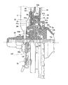
は、図2、図3及び図7(前側のみ図示)に示すように、自転車のフレーム1に回転不能に固定される固定ブラケット30f,30rと、固定ブラケット30f,30rに対向して配置された円筒状のブレーキドラム40と、固定ブラケット30f,30rにハブ軸回りに揺動自在に装着されたブレーキ動作部33f,33rと、ブレーキドラム40に制動作用する複数のブレーキシュー41と、を有している。
<Brake device configuration>
The front and
2, FIG. 3 and FIG. 7 (only the front side is shown), the fixed
固定ブラケット30f,30rは、ブレーキ装置13f,13rをフレーム1のフロントフォーク3又はチェーンスティ2a(図1)に装着するためのものである。固定ブラケット30f,30rは、たとえば鋼板をプレス成形して得られた第1面及び第2面を有するブラケット本体34と、ブラケット本体34に嵌合固定されブラケット本体34の第2面を覆うカバー部材35とを有している。カバー部材35は、金属薄板をプレス成形して形成されており、その表面に焼付塗装が施されかつ型番などの意匠が施されている。
The fixing
ブラケット本体34は、ハブ軸15a(図6に前側のみ図示)が貫通する基部34aと、基部34aから実質的に径方向に延びる先細りのアーム部34bと、アーム部34bの先端に形成された実質的に等幅の板状の係止部34cとを有している。
The
ブラケット本体34の基部34aは、図6に示すように、ハブ軸15aの一端にねじ込まれた袋ナット45により押圧されてハブ軸15aに固定されている。基部34aにはアーム部34bの延出部分を除いて僅かな長さで筒部34dが形成されている。この筒部34dには、後述するブレーキドラム40の脱落を防止する第1抜け止め部材36,37を装着するための1対の装着孔38a,38bからなる部材装着部38が形成されている。
As shown in FIG. 6, the
ブラケット本体34の係止部34cは、ブラケット固定部材25f,25rに固定されている。前側のブラケット本体34の係止部34cは、前輪6の着脱を容易にするためにブラケット固定部材25fにワンタッチで着脱可能に係止されている。前側の係止部34cの第1面(図6の表面)には、装着方向に延びかつ凹んだ凹部34eが形成されている。
The locking
ブラケット固定部材25f及び固定ブラケット30rには、アウターケーブル17f,17rを係止可能なアウター装着部31f,31rがそれぞれ装着されている。前側のブラケット固定部材25fには、アウター装着部31fがねじ止め固定されている。図4に示すように、アウター装着部31fは、アウターケーブル17fを係止可能なアウター係止部31aと、アウター係止部31aのケーブル軸線方向の係止位置をねじにより調整可能にアウター係止部31aを固定するアウター固定部31bとを有している。この軸線位置の調整によりブレーキの遊び(ブレーキドラムとブレーキシューとの隙間)を調整できる。
Outer mounting
なお、以降の説明では、前後のブレーキ装置13f,13rにおいて、概ね構成が同じであるため、前ブレーキ装置13fの構成について説明する。
In the following description, the front and
<ブレーキドラムの構成>
ブレーキドラム40は、図6に示すように、ハブと一体回転可能であり内周面に制動面51aを有する円筒状のドラム本体43と、ブレーキドラム40の外周側に固定されブレーキドラム40に固定された冷却ディスク44とを有している。
<Brake drum configuration>
As shown in FIG. 6, the
ドラム本体43は、開口50aを有する底部50と、底部50の外周側に形成された円周部51とを有する鉄製の皿状の部材である。開口50aの内周面には、ハブシェル15bを構成する左玉受け15cの外周面に一体回転可能に装着される凹凸部50bが形成されている。
The drum main body 43 is an iron dish-shaped member having a
円周部51の内周面には、円形の制動面51aが形成されている。制動面51aは、断面が径方向外方にいくにつれて幅が狭くなる等脚台形状に円周部51の軸方向中央部に凹んで形成されている。制動面51aの両辺が交差する角度は80度から100度の範囲が好ましい。制動面51aは、制動面に径方向外方に向けて凹んで形成されグリースが内部に充填される環状のグリース充填溝54を内周面に有している。グリース充填溝54は、制動面51aの最も凹んだ部分に形成されている。グリース充填溝54には組立時にグリースが充填されている。
A
冷却ディスク44は、図4〜図7に示すように、アルミニウム合金製の部材であり、ドラム本体43の外周面に圧入及びカシメにより固定されたものである。前側の冷却ディスク44には、多数の冷却フィン44aが内側面(図4右側面)に放射状に形成されている。
As shown in FIGS. 4 to 7, the
このように、冷却ディスク44をドラム本体43に圧入後カシメ固定することにより、冷却ディスク44をドラム本体43に確実に固定できる。この圧入及びカシメによる作業は熱を加える必要がないとともに同じ場所で行える。このため、熱による変色や変形を防止できるとともに、製造作業の手間も簡素になり、冷却ディスク44をドラム本体43に簡単かつ安価に固定できるようになる。
In this manner, the
<ブレーキ動作部の構成>
ブレーキ動作部33f,33rは、形状は異なるが略同一の構成であるので、ここでは、前ブレーキ動作部33fについて説明する。前ブレーキ動作部33fは、固定ブラケット30fに揺動自在に設けられ、ブレーキシュー41をブレーキドラム40側に圧接させるものである。
<Configuration of brake operation unit>
Since the
前ブレーキ動作部33fは、図6及び図7に示すように、動作アーム部60と、動作アーム部60と一体的に回動するカム部材61と、カム部材61とブレーキシュー41との間に配置されたローラ62と、を有している。また、ブレーキ動作部33fは、カム部材61とブレーキシュー41との間に両者に接触しかつ回転方向に間隔を隔てて設けられた複数(例えば6つ)のローラ62と、回転方向に間隔を隔ててローラ62を保持するローラケース63とをさらに有している。
As shown in FIGS. 6 and 7, the front
<動作アーム部の構成>
動作アーム部60は金属板材の部材である。動作アーム部60は、固定ブラケット30fのブラケット本体34に、ハブ軸15a回りに制動解除位置(図10)と、制動位置(図11)とに揺動自在に装着されている。動作アーム部60の先端には制動ケーブル14fのインナーケーブル16fの先端を係止するインナー装着部64が着脱自在に装着されている。このインナーケーブル16fによりインナー装着部64を介して動作アーム部60は、自転車のハンドル部4に装着された制動レバー12fと連結される。動作アーム部60の基端は、折れ曲がってブラケット本体34の基部の内側に挿入されている。挿入部分には、カム部材61の外周面に係合する係合孔60a(図6,図7)が形成されている。動作アーム部60は、第2ばね部材70(図7)により制動解除方向に付勢されている。第2ばね部材70は、捩じりコイルばねであり、一端がブラケット本体34に係止され、他端が動作アーム部60の先端まで延び先端に形成された係止孔60bに係止されている。動作アーム部60の外方はカバー部材35により覆われている。動作アーム部60の先端にインナー装着部64が着脱自在に装着される。インナー装着部64は、インナーケーブル16fを係止可能なインナー係止部68を有している。
<Configuration of operation arm>
The
<カム部材の構成>
カム部材61は、動作アーム部60に一体回動可能にカシメ固定されており、動作アーム部60の揺動により回動する。カム部材61は、図7、図8及び図10に示すように、厚肉円筒状のたとえば鋼鉄製の部材である。カム部材61の外周面には、制動レバー12fのレバーストロークに比例して外径が徐々に大きくなる傾斜カム面61aと、傾斜カム面61aの間に配置され傾斜カム面61aより凹んで形成された凹部61bとを有する第1カム部61cが形成されている。この実施形態では、傾斜カム面61aは、図10の時計回りに周方向の外径が徐々に大きくなるように形成されている。具体的には、カム角度が一定に設定されている。このため、第1カム部61cによりローラ62を押圧すると、動作アーム部60の揺動位置に関わらず一定の制動特性が得られる。
<Composition of cam member>
The
<ローラの構成>
ローラ62は、カム部材61の回動によりブレーキシュー41を径方向に押圧してブレーキシュー41に圧接させるためのものである。ローラ62は、カム部材61の外周面とブレーキシュー41の後述する第2カム部41dとの間に装着されている。ローラ62はローラケース63によりブレーキドラム40の回転方向に間隔を隔てて配置され径方向に移動自在である。ローラ62は、カム部材61の回動により転動しつつ径方向に移動する。具体的には、ローラ62はカム部材61の回動によって時計回りに自転しながら反時計回りに公転し、ローラケース63はローラ62の公転によって反時計回りに移動する。
<Roller configuration>
The
<ローラケース63の構成>
ローラケース63は、ハブ軸回りに僅かな距離だけ回動可能である。ローラケース63には、ローラ62を保持するためのハブ軸方向外方に突出した、たとえば6つの保持突起63aが回転方向に間隔を隔てて形成されている。一つの保持突起63aにさらにハブ軸方向外方に突出して形成された係止突起63bが形成されている。この係止突起63bは、ブラケット本体34に制動開始位置から僅かな距離だけハブ軸回りに移動可能に係止されている。ブラケット本体34には、図5、図6及び図7に示すように、この係止突起63bが係合する円周方向に長い円弧状の長孔34gが形成されている。長孔34gは、円周方向の長さが係止突起63bより長い。この長さの差だけローラケース63は、制動開始位置から円周方向に回動可能である。ローラケース63と係止突起63bとの間には第3ばね部材72が装着されている。第3ばね部材72は、ローラケース63を図5の時計回りに制動解除位置に向けて付勢している。このため、ローラケース63に保持されたローラ62は、カム部材61の回動によりブレーキドラム40に対して反時計回りに僅かの距離(長孔34gと係止突起63bの円周方向の長さの差の距離)だけ転動可能である。ローラケース63内において、ローラ62の周囲には防錆油が充填されている。これにより、カム部材61の回動に対してローラ62がスムーズに径方向に移動できる。
<Configuration of
The
<ブレーキシューの構成>
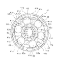
ブレーキシュー41は、図8に示すように、たとえば周方向で3つに分割されたリング状の、例えばクロムモリブデン鋼製の部材である。ブレーキシュー41は、カム部材61とでローラ62を挟むように配置されている。ブレーキシュー41は、図6に示すように、制動時に制動面51aに接触可能に接触面41aを外周面に有している。接触面41aは、断面が制動面51aに接触可能に凸に突出した等脚台形状に形成されている。接触面41aの両辺が交差する角度は、制動面51aの交差角度より大きいか等しい。接触面41aの中央部には、第1ばね部材53が装着される環状の収納溝41bが形成されている。収納溝41bは、グリース充填溝54の第1溝54aに対向するように形成されている。
<Brake shoe configuration>
As shown in FIG. 8, the
ブレーキシュー41の内周面には、回転方向に所定の長さで形成された回転止め部41cが径方向外方に凹んで形成されている。この回転止め部41cに固定ブラケット30fのブラケット本体34に形成された3つの係止突起34f(図6,図7)がはまり込み、分割されたブレーキシュー41の回転を防止している。ただし、係止突起34fと回転止め部41cとの遊び分はブレーキシュー41が僅かに回転する。
On the inner peripheral surface of the
分割されたブレーキシュー41の回り止め部41cの両側内周面には、図8に示すように、ローラ62に係合する第2カム部41dが形成されている。第2カム部41dは、ローラ62との接触部分に内径が徐々に変化するように形成されている。第2カム部41dは、制動解除時にローラ62が配置される制動解除カム41eと、制動解除カム41eの両側に配置された制動カム41f,49gと、を有している。
As shown in FIG. 8,
制動解除カム41eは、回動中心C1を中心とし回動中心C1からの内径が最も大きい円弧状の部分である。制動解除カム41eは、制動カム41fとの間には、段差41hが形成されている。段差41hは、制動解除カム41eと制動カム41fとの間をつなぐ円弧で構成されている。前ハブ6aの回動中心C1から段差41hの始点及び終点を結ぶ2本の直線L1,L2の差で表せる段差41hの径方向の長さは、0.3mmから0.7mmの範囲である。
The
制動カム41fは、例えば前輪用のブレーキ装置13fに用いられ、制動カム41gは、後輪用のブレーキ装置13rに用いられる。ブレーキ装置13fの動作アーム部60は、制動時に図2反時計回りに揺動し、ブレーキ装置13rの動作アーム部60は、図2時計回りに揺動する。このため、カム部材61の回動方向が前輪用と後輪用とでは逆方向になる。この結果、ローラ62の公転方向も逆になり、前輪用の場合は、ローラ62が制御カム41f側に反時計回りに公転し、後輪用の場合は、時計回りに公転する。
The
制動カム41fは、制動解除カム41e側の第1位置D1での回動中心C1からの距離が第1位置D1から離反した第2位置D2での回動中心C1からの距離より長く形成された傾斜カム面を有している。具体的には、制動カム41fは、第1位置D1での回動中心C1から延びる直線L2の長さより第2位置D2での直線L3の長さが短くかつ第1位置D1から第2位置D2に向かって回動中心C1からの距離が徐々に短くなるような傾斜カム面を有している。この実施形態では、傾斜カム面は、概ね円弧状の曲線で構成されている。傾斜カム面の円弧の中心C2は、回動中心C1より制動解除カム41eに接近しかつ制動解除カム41eの中心部と回動中心C1とを結ぶ直線L4より逆側の制動カム41f側に変位した位置にある。なお、傾斜カム面の中心C2は、上記位置に限定されない。また、傾斜カム面を円弧ではなく、複数の連続する直線や円弧と異なる曲線で形成してもよい。
The
制動カム41gは、制動カム41fと制動解除カム41eを挟んで同じ割合で内径が徐々に小さくなるように形成されている。したがって、制動カム41fと制動カム41gとは、直線L4を挟んで線対称に配置されている。このため、たとえば、制動カム41fを前輪用のブレーキ装置13fに用い、制動カム41gを後輪用のブレーキ装置13rに用いても略同等の制動特性が得られる。
The brake cam 41g is formed so that the inner diameter gradually decreases at the same rate across the
なお、図9では、回動中心C1と中心C2との半径方向の距離は正確には表されていない。 In FIG. 9, the distance in the radial direction between the rotation center C1 and the center C2 is not accurately represented.
第1ばね部材53は、弾性線材を円形に湾曲して形成された環状のばね部材である。第1ばね部材53は、3つの分割されたブレーキシュー41をブレーキドラム40から離反する位置、つまり径方向内方に付勢している。第1ばね部材53の一端には、径方向外方に折り曲げて突出した突出部53aが形成されている。突出部53aは、内周部から1.4mm〜2.0mmの範囲で突出して形成されている。突出部53aの先端は、ブレーキシュー41がブレーキドラム40に接触する制動時にグリース充填溝54の第1溝54a内に位置し、ブレーキシュー41がブレーキドラム40から離反する制動解除時に第1溝54a溝より径方向内方に位置する。これにより、制動時に突出部53aは、第1溝54aに充填されたグリースを制動面51aに向けてかき出すことができる。
The
<制動システムの動作>
制動ケーブル14f,14rをセットした状態では、インナーケーブル16f,16rは緊張状態になっているため、制動レバー12f,12rに装着されたアウター係止部22又は前後のブレーキ装置13f,13rに装着されたアウター装着部31f,31rによって遊びを調整する。これにより、制動レバー12f,12rを操作しないと、図10に示すように、ブレーキシュー41とブレーキドラム40との間に隙間(遊び)が形成される。
<Brake system operation>
In a state where the
この状態で前制動レバー12fを引き込み操作すると、インナーケーブル16fが第2ばね部材70の付勢力に抗して引っ張られ、動作アーム部60が図10に示す制動解除位置から図11に示す制動位置に反時計回りに揺動する。動作アーム部60が反時計回りに回動すると、カム部材61も回動する。カム部材61が回動すると、ローラ62が第1カム部61cの傾斜カム面61aに乗り上げる。これよりローラ62が傾斜カム面61aに押圧されて第1ばね部材53の付勢力に抗して径方向外方に移動する。この移動途中で、ブレーキシュー41がブレーキドラム40に接触すると、ローラ62がブレーキシュー41をブレーキドラム40に向けて押圧する。また、ローラ62がカム部材61との摩擦等により図9に矢印Rで示す時計回りに転動し、ローラケース63が反時計回りに回動する。
When the
ローラ62が時計回りに転動すると、ローラ62は、第2カム部41dの制動解除カム41eから図9左側の制動カム41fに向かって移動する。この結果、第1カム部61cの径方向の増加量に加えて第2カム部41dの径方向の減少量が加わって、レバーストロークに対して直線的に増加する制動力が得られる。
When the
この様子を図12及び図13にグラフで示す。図12は、制動レバー12fの操作力を横軸に、制動力を縦軸に表したグラフである。また、図13は、制動レバー12fのレバーストロークを横軸に、制動力を縦軸に表したグラフである。ここで、実線は、ブレーキシュー41の内周面に第2カム部41dを有する本発明の一実施形態によるブレーキ装置13fを示している。破線は、第1カム部を有さずかつカム部材の第1カム部のカム角度が一定の比較対照の従来のブレーキ装置を示している。
This is shown graphically in FIGS. FIG. 12 is a graph showing the operating force of the
図12及び図13から明らかなように、第2カム部41dの有無以外は全く同じ本実施形態のブレーキ装置13fと従来のブレーキ装置とを比較した場合、レバー操作力又はレバーストロークが小さいときの制動力は略同じである。レバー操作力又はレバーストロークが大きいときの制動力は、第2カム部41dがある本実施形態のブレーキ装置13fの方が小さくなる。
As is clear from FIGS. 12 and 13, when the
従来の第2カム部を有さないブレーキ装置では、レバー操作力又はレバーストロークを徐々に大きくしていくと突然制動力が曲線的に上がる。これに対し、第2カム部41dを有するブレーキ装置13fでは、レバー操作力又はレバーストロークが大きいときでも制動力が突然大きくなることはなく、直線的になる。
In a conventional brake device that does not have the second cam portion, the braking force suddenly increases as the lever operating force or lever stroke is gradually increased. On the other hand, in the
また、カム部材61が一定のカム角度を有しているので、どのような回動位相にあっても、ブレーキシュー41がブレーキドラム40に接触し制動を開始してからの制動特性が変動しにくい。したがって、制動開始時のカム部材61の回動位置に関わらず制動開始後の制動特性を維持できるようになる。
In addition, since the
前制動レバー12fから手を離すと、第2ばね部材70により動作アーム部60が制動解除位置側に戻されるとともに、動作アーム部60に連動するカム部材61の回動に伴って第1ばね部材53によりブレーキシュー41が内周側に移動する。このとき、ローラケース63も第3ばね部材72により図11時計回りに付勢されて回動する。これにより、ローラ62は、制動解除カム41eに配置される。
When the hand is released from the
<他の実施形態>
以上、本発明の一実施形態について説明したが、本発明は上記実施形態に限定されるものではなく、発明の要旨を逸脱しない範囲で種々の変更が可能である。
<Other embodiments>
As mentioned above, although one Embodiment of this invention was described, this invention is not limited to the said embodiment, A various change is possible in the range which does not deviate from the summary of invention.
(a)前記実施形態では、制動面51aや接触面41aを台形状に形成したが、平坦な円周面であってもよい。
(A) In the above embodiment, the
(b)前記実施形態では、第2カム部41dをブレーキシュー41の内周面に一体形成したが、別体で形成してもよい。
(B) Although the
(c)前記実施形態では、同じカム形状の制動カム41f,41gを制動解除カム41eの両側に配置した。このように、二つの制動カムのカム形状を同じにすれば、前輪用と後輪用とでブレーキシューの共通化を図れる。また、表裏を反転しても使用できるため、組立ミスを減少できる。しかし、本発明はこれに限定されない。たとえば、異なる形状の二つの制動カムを、制動解除カムを挟んで配置しても良い。この場合には、ブレーキシューの表裏を反転して装着すると、一つのブレーキシューで異なる制動特性を得ることができる。また、制動解除カムの片側にだけ制動カムを配置しても良い。
(C) In the above embodiment, the
1 フレーム
6,7 前輪及び後輪
6a 前ハブ
13f,13r 前後のブレーキ装置
30f,30r 前後の固定ブラケット
33f,33r 前後のブレーキ動作部
40 ブレーキドラム
41 ブレーキシュー
41a 接触面
41d 第2カム部
41e 制動解除カム
41f,41g 制動カム
41h 段差
51a 制動面
60 動作アーム部
61 カム部材
61c 第1カム部
62 ローラ
C1 回動中心
1
Claims (12)
前記フレームに回転不能に装着可能な固定ブラケットと、
内周面に形成された制動面を有し、前記固定ブラケットに対向して配置され前記ハブと一体回転可能な円筒状のブレーキドラムと、
前記固定ブラケットに前記ハブの軸回りに揺動自在に装着され、前記自転車に装着されたブレーキレバーと連結可能な動作アーム部、前記動作アーム部と一体的に回動し、外周面に周方向で外径が徐々に大きくなる第1カム部を有するカム部材、及び前記第1カム部に接触しかつ周方向に間隔を隔てて設けられ、前記カム部材の回動により転動しつつ径方向に移動する複数のローラ、を有するブレーキ動作部と、
前記カム部材とで前記ローラを挟むように配置され、前記ブレーキドラムの前記制動面に接触可能な接触面、及び前記ローラとの接触部分に前記ハブの回動中心との距離が徐々に変化するように形成された第2カム部、を有し、前記固定ブラケットに対して実質的に回転不能であり、前記ブレーキドラムに制動作用する円弧状の複数のブレーキシューと、
を備えた自転車用ハブブレーキ装置。 A bicycle hub brake device capable of braking a wheel hub mounted on a bicycle frame,
A fixing bracket that is non-rotatably mountable to the frame;
A cylindrical brake drum having a braking surface formed on an inner peripheral surface, and arranged to face the fixed bracket and capable of rotating integrally with the hub;
An operating arm portion mounted on the fixed bracket so as to be swingable about the axis of the hub, and connected to a brake lever mounted on the bicycle. And a cam member having a first cam portion having an outer diameter that gradually increases, and a radial direction while being in contact with the first cam portion and spaced apart in the circumferential direction and rolling by rotation of the cam member A brake operating section having a plurality of rollers that move to
The cam member is arranged so as to sandwich the roller, and the distance between the contact surface that can contact the braking surface of the brake drum and the rotation center of the hub gradually changes at the contact portion with the roller. A plurality of arcuate brake shoes that are substantially non-rotatable with respect to the fixed bracket and act on the brake drum.
Bicycle hub brake device with
前記フレームに回転不能に装着可能な固定ブラケットと、
内周面に形成された制動面を有し、前記固定ブラケットに対向して配置され前記ハブと一体回転可能な円筒状のブレーキドラムと、
前記固定ブラケットに前記ハブの軸回りに揺動自在に装着され、前記自転車に装着されたブレーキレバーと連結可能な動作アーム部、前記動作アーム部と一体的に回動し、外周面に周方向で外径が徐々に大きくなる第1カム部を有するカム部材、及び前記第1カム部に接触しかつ回転方向に間隔を隔てて設けられ、前記カム部材の回動により転動しつつ径方向に移動する複数のローラ、を有するブレーキ動作部と、
前記カム部材とで前記ローラを挟むように配置され、前記ブレーキドラムの前記制動面に接触可能な接触面、及び前記ローラとの接触部分の第1位置での前記ハブの回動中心との距離が、前記第1位置から離反した第2位置での前記回動中心との距離と異なるように形成された第2カム部と、を含み、前記固定ブラケットに対して実質的に回転不能であり、前記ブレーキドラムに制動作用する円弧状の複数のブレーキシューと、
を備えた自転車用ハブブレーキ装置。 A bicycle hub brake device capable of braking a wheel hub mounted on a bicycle frame,
A fixing bracket that is non-rotatably mountable to the frame;
A cylindrical brake drum having a braking surface formed on an inner peripheral surface, and arranged to face the fixed bracket and capable of rotating integrally with the hub;
An operating arm portion mounted on the fixed bracket so as to be swingable about the axis of the hub, and connected to a brake lever mounted on the bicycle. And a cam member having a first cam portion having an outer diameter that gradually increases, and a radial direction while being in contact with the first cam portion and spaced apart in the rotational direction and rolling by the rotation of the cam member. A brake operating section having a plurality of rollers that move to
A distance between a contact surface that is disposed so as to sandwich the roller with the cam member and can contact the braking surface of the brake drum, and a rotation center of the hub at a first position of a contact portion with the roller And a second cam portion formed to be different from the distance from the rotation center at the second position separated from the first position, and is substantially non-rotatable with respect to the fixed bracket. A plurality of arc-shaped brake shoes that brake the brake drum;
Bicycle hub brake device with
前記固定ブラケットに制動開始位置から所定距離回動可能に設けられ、前記ローラを周方向に間隔を隔てて配置するローラケースと、
前記ローラケースを前記制動開始位置側に付勢する付勢部材と、をさらに有する、請求項1に記載の自転車用ハブブレーキ装置。 The brake operating unit is
A roller case provided on the fixed bracket so as to be rotatable by a predetermined distance from a braking start position, and disposing the rollers at intervals in the circumferential direction;
The bicycle hub brake device according to claim 1, further comprising a biasing member that biases the roller case toward the braking start position.
前記固定ブラケットに制動開始位置から所定距離回動可能に設けられ、前記ローラを周方向に間隔を隔てて配置するローラケースと、
前記ローラケースを前記制動開始位置側に付勢する付勢部材と、をさらに有する、請求項2に記載の自転車用ハブブレーキ装置。 The brake operating unit is
A roller case provided on the fixed bracket so as to be rotatable by a predetermined distance from a braking start position, and disposing the rollers at intervals in the circumferential direction;
The bicycle hub brake device according to claim 2, further comprising a biasing member that biases the roller case toward the braking start position.
請求項9に記載の自転車用ハブブレーキ装置。 The bicycle hub brake device according to claim 9, wherein an inner diameter of the brake cam gradually decreases at the same rate across the brake release cam.
The bicycle hub brake device according to claim 9.
Priority Applications (4)
| Application Number | Priority Date | Filing Date | Title |
|---|---|---|---|
| JP2009057660A JP4659100B2 (en) | 2009-03-11 | 2009-03-11 | Bicycle hub brake device |
| AT09168446T ATE538991T1 (en) | 2009-03-11 | 2009-08-24 | BICYCLE HUB BRAKE |
| EP09168446A EP2228291B1 (en) | 2009-03-11 | 2009-08-24 | Bicycle hub braking device |
| CN2009101728157A CN101830267B (en) | 2009-03-11 | 2009-09-03 | Bicycle hub braking device |
Applications Claiming Priority (1)
| Application Number | Priority Date | Filing Date | Title |
|---|---|---|---|
| JP2009057660A JP4659100B2 (en) | 2009-03-11 | 2009-03-11 | Bicycle hub brake device |
Publications (2)
| Publication Number | Publication Date |
|---|---|
| JP2010210028A JP2010210028A (en) | 2010-09-24 |
| JP4659100B2 true JP4659100B2 (en) | 2011-03-30 |
Family
ID=41137612
Family Applications (1)
| Application Number | Title | Priority Date | Filing Date |
|---|---|---|---|
| JP2009057660A Expired - Fee Related JP4659100B2 (en) | 2009-03-11 | 2009-03-11 | Bicycle hub brake device |
Country Status (4)
| Country | Link |
|---|---|
| EP (1) | EP2228291B1 (en) |
| JP (1) | JP4659100B2 (en) |
| CN (1) | CN101830267B (en) |
| AT (1) | ATE538991T1 (en) |
Cited By (1)
| Publication number | Priority date | Publication date | Assignee | Title |
|---|---|---|---|---|
| TWI730249B (en) * | 2017-09-28 | 2021-06-11 | 日商島野股份有限公司 | Braking device |
Families Citing this family (3)
| Publication number | Priority date | Publication date | Assignee | Title |
|---|---|---|---|---|
| CN107054540A (en) * | 2017-02-20 | 2017-08-18 | 宁波彰星车辆有限公司 | A kind of band type brake for bicycle formula roller brake gear |
| CN109693754B (en) * | 2017-10-24 | 2023-11-17 | 广东洛梵狄智能科技有限公司 | Hub brake lock, hub brake system, hub assembly and bicycle |
| CN108488259B (en) * | 2018-05-04 | 2024-01-23 | 湖北中尔车轴有限公司 | Automobile peripheral disc type braking system |
Citations (4)
| Publication number | Priority date | Publication date | Assignee | Title |
|---|---|---|---|---|
| JPH0713686U (en) * | 1993-08-11 | 1995-03-07 | 株式会社シマノ | Inner expansion hub brake for bicycles |
| JPH082471A (en) * | 1994-06-23 | 1996-01-09 | Shimano Inc | Hub brake for bicycle |
| JP2000329168A (en) * | 1999-05-19 | 2000-11-28 | Yamaha Motor Co Ltd | Drum brake for vehicle |
| JP3682957B2 (en) * | 2001-09-12 | 2005-08-17 | 株式会社シマノ | Bicycle hub brake device |
Family Cites Families (8)
| Publication number | Priority date | Publication date | Assignee | Title |
|---|---|---|---|---|
| EP0064839A1 (en) * | 1981-05-01 | 1982-11-17 | Shimano Industrial Company Limited | Cycle hub brake |
| JP2702350B2 (en) * | 1992-03-23 | 1998-01-21 | 株式会社シマノ | Bicycle braking device |
| US5524734A (en) * | 1993-06-07 | 1996-06-11 | Shimano, Inc. | Brake apparatus for a bicycle which corrects braking force in a region of strong braking force |
| JP2597742Y2 (en) * | 1993-08-11 | 1999-07-12 | 株式会社シマノ | Bicycle hub brake |
| CN2326513Y (en) * | 1997-06-06 | 1999-06-30 | 天津市南洋新技术设计研究所 | Overrun-clutching type cam bicycle expanding brake |
| US6290028B1 (en) * | 2000-05-09 | 2001-09-18 | Liu Jen-Chih | Bike brake |
| EP1157920A1 (en) * | 2000-05-23 | 2001-11-28 | Jen-Chih Liu | Bicycle brake |
| JP3703780B2 (en) * | 2002-06-11 | 2005-10-05 | 株式会社シマノ | Bicycle hub brake device |
-
2009
- 2009-03-11 JP JP2009057660A patent/JP4659100B2/en not_active Expired - Fee Related
- 2009-08-24 AT AT09168446T patent/ATE538991T1/en active
- 2009-08-24 EP EP09168446A patent/EP2228291B1/en not_active Not-in-force
- 2009-09-03 CN CN2009101728157A patent/CN101830267B/en active Active
Patent Citations (4)
| Publication number | Priority date | Publication date | Assignee | Title |
|---|---|---|---|---|
| JPH0713686U (en) * | 1993-08-11 | 1995-03-07 | 株式会社シマノ | Inner expansion hub brake for bicycles |
| JPH082471A (en) * | 1994-06-23 | 1996-01-09 | Shimano Inc | Hub brake for bicycle |
| JP2000329168A (en) * | 1999-05-19 | 2000-11-28 | Yamaha Motor Co Ltd | Drum brake for vehicle |
| JP3682957B2 (en) * | 2001-09-12 | 2005-08-17 | 株式会社シマノ | Bicycle hub brake device |
Cited By (1)
| Publication number | Priority date | Publication date | Assignee | Title |
|---|---|---|---|---|
| TWI730249B (en) * | 2017-09-28 | 2021-06-11 | 日商島野股份有限公司 | Braking device |
Also Published As
| Publication number | Publication date |
|---|---|
| CN101830267A (en) | 2010-09-15 |
| CN101830267B (en) | 2012-11-14 |
| ATE538991T1 (en) | 2012-01-15 |
| EP2228291A1 (en) | 2010-09-15 |
| EP2228291B1 (en) | 2011-12-28 |
| JP2010210028A (en) | 2010-09-24 |
Similar Documents
| Publication | Publication Date | Title |
|---|---|---|
| EP1595780B2 (en) | Apparatus for mounting a hub brake to a bicycle frame | |
| JP2607289Y2 (en) | Speed change device for bicycle | |
| JP4659100B2 (en) | Bicycle hub brake device | |
| JP4073929B2 (en) | Bicycle wheel drive device | |
| JP3571662B2 (en) | Cable operated disc brake | |
| JP2597741Y2 (en) | Bicycle brake lever device | |
| JP4455553B2 (en) | Bicycle brake device | |
| JPH1086881A (en) | Brake device for bicycle | |
| JP3784348B2 (en) | Bicycle hub brake device mounting structure | |
| JP3740093B2 (en) | Bicycle hub brake device | |
| JP3740092B2 (en) | Bicycle hub brake device | |
| JP3703780B2 (en) | Bicycle hub brake device | |
| JP3720002B2 (en) | Bicycle hub brake device | |
| CN110466661B (en) | Cable regulator | |
| EP1759977B1 (en) | Apparatus for mounting a brake control element to a bicycle hub brake | |
| JP3682957B2 (en) | Bicycle hub brake device | |
| TWI611120B (en) | Mechanism of drum brake | |
| JP3612094B2 (en) | Bicycle brake device | |
| JP2557725Y2 (en) | Slack adjuster device |
Legal Events
| Date | Code | Title | Description |
|---|---|---|---|
| TRDD | Decision of grant or rejection written | ||
| A01 | Written decision to grant a patent or to grant a registration (utility model) |
Free format text: JAPANESE INTERMEDIATE CODE: A01 Effective date: 20101207 |
|
| A01 | Written decision to grant a patent or to grant a registration (utility model) |
Free format text: JAPANESE INTERMEDIATE CODE: A01 |
|
| A977 | Report on retrieval |
Free format text: JAPANESE INTERMEDIATE CODE: A971007 Effective date: 20101209 |
|
| A61 | First payment of annual fees (during grant procedure) |
Free format text: JAPANESE INTERMEDIATE CODE: A61 Effective date: 20101224 |
|
| FPAY | Renewal fee payment (event date is renewal date of database) |
Free format text: PAYMENT UNTIL: 20140107 Year of fee payment: 3 |
|
| R150 | Certificate of patent or registration of utility model |
Ref document number: 4659100 Country of ref document: JP Free format text: JAPANESE INTERMEDIATE CODE: R150 Free format text: JAPANESE INTERMEDIATE CODE: R150 |
|
| R250 | Receipt of annual fees |
Free format text: JAPANESE INTERMEDIATE CODE: R250 |
|
| R250 | Receipt of annual fees |
Free format text: JAPANESE INTERMEDIATE CODE: R250 |
|
| R250 | Receipt of annual fees |
Free format text: JAPANESE INTERMEDIATE CODE: R250 |
|
| R250 | Receipt of annual fees |
Free format text: JAPANESE INTERMEDIATE CODE: R250 |
|
| R250 | Receipt of annual fees |
Free format text: JAPANESE INTERMEDIATE CODE: R250 |
|
| R250 | Receipt of annual fees |
Free format text: JAPANESE INTERMEDIATE CODE: R250 |
|
| R250 | Receipt of annual fees |
Free format text: JAPANESE INTERMEDIATE CODE: R250 |
|
| LAPS | Cancellation because of no payment of annual fees |