JP4657268B2 - tightening structure - Google Patents
tightening structure Download PDFInfo
- Publication number
- JP4657268B2 JP4657268B2 JP2007220262A JP2007220262A JP4657268B2 JP 4657268 B2 JP4657268 B2 JP 4657268B2 JP 2007220262 A JP2007220262 A JP 2007220262A JP 2007220262 A JP2007220262 A JP 2007220262A JP 4657268 B2 JP4657268 B2 JP 4657268B2
- Authority
- JP
- Japan
- Prior art keywords
- nut
- pin
- bolt
- guide
- screw
- Prior art date
- Legal status (The legal status is an assumption and is not a legal conclusion. Google has not performed a legal analysis and makes no representation as to the accuracy of the status listed.)
- Expired - Fee Related
Links
Images


Description
この発明は、締結構造に関するものである。 The present invention relates to a fastening structure.
従来から、ボルトがナットに対して著しく傾斜した状態で螺入される締付けミスを防止するために、ボルトの雄ネジの端部側に雄ネジの山径よりもやや小径に形成された軸状のガイドピン部を設けて、締付け開始時のボルトを正しい角度に導く締結構造が知られている(例えば、特許文献1参照)。 Conventionally, in order to prevent a tightening mistake that the bolt is screwed in a state of being significantly inclined with respect to the nut, the shaft shape formed on the end side of the male screw of the bolt is slightly smaller than the diameter of the male screw. A fastening structure is known in which a guide pin portion is provided to guide a bolt at the start of tightening to a correct angle (see, for example, Patent Document 1).
上述の締結構造の場合、締付けミスをある程度低減することができるものの、例えば、傾斜状態で設置されているものに対して締付け作業を行う場合など、図6に示すように、締付け開始時のナット100に対するボルト200の傾きが比較的大きくなり、ガイドピン300を設けていても締付けミスが発生する可能性があった。そして、この締付け箇所が電気配線などのターミナルである場合、後に締付けミスによるボルト200の緩み等が発生して接触不良となる虞があるため、より確実な締結構造が要望されていた。
In the case of the above-described fastening structure, although a fastening error can be reduced to some extent, as shown in FIG. 6, for example, when a fastening operation is performed on an object installed in an inclined state, the nut at the start of fastening The inclination of the
例えば、上述のような締付けミスを防止するために、ボルト200のガイドピン300を長尺化し、ナット100の厚さ寸法を増加させることで、締付け開始時のボルト200の傾きをさらに減少させることができるが、このように構成した場合、専用のナットが必要となり、コストが増加してしまう。そこで、汎用ナットを用いる構成として、例えば、ナットの雌ネジ部の軸線に沿うボルト締付け方向に筒状部を設けてボルトのガイドピンを案内することが考えられる。
For example, in order to prevent the above-described tightening error, the
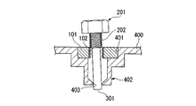
具体的には、図7の参考例に示すように、ボルト201のネジ部202の端部から軸方向に沿って延びる円柱状のガイドピン301を設け、一方、ケーシング400にナット101が没入される凹部401を形成し、さらに、この凹部401の内側にガイドピン301よりも若干短い筒状部402を形成し、この筒状部402の出口に前述のガイドピン301と略同径の内径を備えたガイド孔403を設けることで、ボルト201の締付け開始時にガイドピン301がガイド孔403に導かれ、ナット401に対するボルト201の傾斜角度を締付けミスとならない範囲まで減少させることができ、この結果、汎用のナット101を使用しつつ、上述した従来の締結構造よりも締付けミスを低減することができる。
ところで、上述の参考例に示した締結構造では、汎用のナット101を利用できるものの、汎用のナット101はそのネジ孔102の位置が中心から若干ずれている場合があるため、ナット101のネジ孔102の中心とガイド孔403の中心とがずれてしまい、図7に示すように、直接的な締付けミスの原因にはならない程度ではあるが、ボルト201のネジ部202の雄ネジとナット101ネジ孔102の雌ネジとが有する裕度(ガタ)分だけ傾斜した状態でボルトが螺入されて行くこととなる(図8参照)。
しかしながら、このボルト201の締付け完了直前(図9参照)には、ボルト201の頭部203の下面204がナット101の上面103に対して密着しようとして、ガイドピン301の位置がガイド孔403の径方向外側(図9中、矢印で示す)に変位するため、ガイドピン301の周面がガイド孔403を内側から押圧して、ガイド孔403やその周囲に負担をかけたり、ボルト201の締付け完了を阻害したりする虞がある。
By the way, in the fastening structure shown in the above-mentioned reference example, although the general-
However, immediately before the completion of tightening of the bolt 201 (see FIG. 9), the
そこで、この発明は、汎用のナットを利用して確実な締結が可能であるとともに、ガイド孔やその周囲に負担をかけたり、ボルトの締付け完了を阻害したりするのを防止することができる締結構造を提供するものである。 Therefore, the present invention can be securely fastened by using a general-purpose nut, and can prevent a load from being applied to the guide hole and its surroundings or hindering the completion of bolt tightening. Provide structure.
上記の課題を解決するために、請求項1に記載した発明は、ナット(例えば、実施の形態におけるナット6)を備えた締結部(例えば、実施の形態におけるターミナル部2)に前記ナットに螺合されるボルト(例えば、実施の形態におけるボルト3)によって被締結部を締結接続する締結構造において、前記ボルトのネジ部(例えば、実施の形態におけるネジ部5)の端部より延出形成されるとともにネジ部の外径よりもやや縮径されたピン(例えば、実施の形態におけるガイドピン7)と、外壁に前記ナットを収容する凹部が形成されたケーシングと、を備え、該ケーシングには前記凹部の内側に向かってガイド筒が形成され、該ガイド筒の内周が前記ナットのネジ孔よりも拡径して形成され、前記ガイド筒の端部には、前記ピンを案内するガイド孔(例えば、実施の形態におけるガイド孔15)が形成され、該ガイド孔は、前記ガイド筒の内径よりも小径で且つ前記ピンの外径よりも大径に形成されて、螺合する前の前記ボルトの傾斜角度を所定範囲とするべく螺入する直前の前記ボルトの前記ピンと当接して該ピンを案内可能な所定の距離だけ前記ナットから離間した位置に設けられ、前記所定範囲は、前記ボルトのネジ部がナットのネジ孔に螺入可能な角度範囲であり、前記ピンは、前記ボルトの締付けが完了した際の前記ガイド孔に対応する位置に、該ガイド孔による前記ピンの案内を解除するくびれ部(例えば、実施の形態におけるくびれ部9)を備えることを特徴とする。
In order to solve the above-described problems, the invention described in claim 1 is characterized in that a fastening portion (for example, the
請求項2に記載した発明は、請求項1に記載の発明において、前記ピンの前記くびれ部より前記ネジ部側の基部と、前記ピンの前記くびれ部より前記ネジ部とは反対側の先端部とがそれぞれ前記ナットの厚さ寸法と略同一寸法に設定されていることを特徴とする。 According to a second aspect of the present invention, in the first aspect of the present invention, a base portion on the screw portion side from the constricted portion of the pin, and a tip portion on the opposite side of the screw portion from the constricted portion of the pin. Are set to be substantially the same as the thickness of the nut.
請求項3に記載した発明は、前記ガイド孔の前記ナット側の周縁には、前記ピンを案内するテーパ面(例えば、実施の形態におけるテーパ面16)が設けられていることを特徴とする。
The invention described in claim 3 is characterized in that a taper surface for guiding the pin (for example, a
請求項1に記載した発明によれば、ナットから所定の距離だけ離間したガイド孔を有し、ボルトがこのガイド孔に案内されるピンを備えることで、ボルトの締付け開始時のナットに対するボルトの傾斜角度をガイド孔の離間距離が長くなるほど小さくすることができるため、汎用ナットを用いてコストを低減しつつ、確実な締結を行うことができる効果がある。 According to the first aspect of the present invention, the bolt has the guide hole that is separated from the nut by a predetermined distance, and the bolt is provided with a pin that is guided by the guide hole. Since the inclination angle can be reduced as the distance between the guide holes becomes longer, there is an effect that reliable fastening can be performed while reducing the cost by using a general-purpose nut.
また、例えば、ナットのネジ孔の中心軸とガイド孔の中心軸とが若干ずれている場合、ボルトとナットとの裕度の分だけボルトが傾斜した状態で螺入され、ボルトの螺入が完了する際にボルトのネジ部がナットのネジ孔に対して真っ直ぐな状態に変位しようとするが、くびれ部を設けたことでガイド孔によるピンの案内が解除されるため、ピンがガイド孔の内周面を押圧してガイド孔やその周囲へ負担をかけたり、ボルトの締付け完了を阻害したりするのを防止することができる効果がある。 Also, for example, when the center axis of the screw hole of the nut and the center axis of the guide hole are slightly shifted, the bolt is screwed in with the bolt and the nut being inclined by the margin of tolerance. When completed, the screw thread of the bolt tries to be displaced straight with respect to the screw hole of the nut, but the guide of the pin by the guide hole is released by providing the constricted part, so the pin is not in the guide hole. There is an effect that it is possible to prevent the inner peripheral surface from being pressed to place a burden on the guide hole and its surroundings or to inhibit the completion of bolt tightening.
請求項2に記載の発明によれば、請求項1に記載の効果に加え、ナットの厚さよりもピンの全長が十分長くなるため、ボルト締付け開始時のナットに対するボルトの傾斜角度を極めて小さく設定することができ、したがって、締付けミスを確実に防止することができる効果がある。
また、ピンの長さをネジ部の傾き防止の効果を得るための必要最小限の長さとすることができるため、締結部の小型化を図ることができる。
According to the invention described in
In addition, since the length of the pin can be set to the minimum necessary length for obtaining the effect of preventing the inclination of the screw portion, the fastening portion can be reduced in size.
請求項3に記載した発明によれば、請求項1又は2の効果に加え、ガイド孔のナット側の周縁にテーパ面を形成したことで、ボルトを締付け開始位置に導く際にスムーズにピンがガイド孔に挿入されるため、作業性の向上を図ることができ、作業者の負担を軽減することができる効果がある。 According to the third aspect of the invention, in addition to the effect of the first or second aspect, the tapered surface is formed on the nut side periphery of the guide hole, so that the pin can be smoothly inserted when the bolt is guided to the tightening start position. Since it is inserted into the guide hole, it is possible to improve workability and to reduce the burden on the operator.
次に、図面を参照しながらこの発明の実施の形態を説明する。この実施の形態にあっては、車両のヒューズボックスに電源端子を接続する締結部であるターミナル部を一例に説明する。なお、図示都合上、この実施の形態では電源端子の図示を省略している。
図1,2に示すヒューズボックス1は、例えば、車両のインスツルメントパネル下方に傾斜状態で固定されたものである。作業者はヒューズボックス1が傾斜して固定されているため、電源端子をターミナル部2に固定する際に、ボルト3をヒューズボックス1の傾斜に合わせて斜め方向にセットし、インパクトドライバーなどにより締付け固定する。
Next, embodiments of the present invention will be described with reference to the drawings. In this embodiment, a terminal part that is a fastening part for connecting a power terminal to a fuse box of a vehicle will be described as an example. For the sake of illustration, the power supply terminals are not shown in this embodiment.
The fuse box 1 shown in FIGS. 1 and 2 is, for example, fixed in an inclined state below a vehicle instrument panel. The operator fixes the fuse box 1 at an angle, so when fixing the power terminal to the
ボルト3は、ヘクスローブやヘキサゴンなどのネジ頭4を有したものであり、このネジ頭4の中心に、雄ネジであるネジ部5の基端側が接続されている。ネジ部5は、ナット6の雌ネジよりも若干長く形成されており、その端部側には、所定長さのガイドピン7が延出して形成されている。
The bolt 3 has a
ガイドピン7は、ネジ部5の外径よりも若干縮径されネジ部5側に配置された基部8aと、この基部8aと略同一の外径を有しネジ部5とは反対側に配置された端部8bと、これら基部8aと端部8bとの間に形成されたくびれ部9とで構成されている。くびれ部9は、ガイドピン7の軸方向に沿って所定の幅を有しており、基部8aおよび端部8bよりも縮径して有段成形されている。基部8aおよび端部8bのそれぞれの軸方向に沿った長さは、ナット6のネジ孔10の長さdよりもやや長く設定されている。つまり、ガイドピン7は、ネジ孔10の長さdの2倍よりも十分に長い寸法で形成されている。ここで、ネジ頭4とネジ部5との形状はJIS規格等の規格に準じている。
The
一方、ナット6は、いわゆる汎用のナットであり、その外形は上面視略四角形状に形成され中央部分には雌ネジであるネジ孔10を有している。このナット6はヒューズボックス1のケーシング11に埋設又は嵌合により回転が規制された状態で収容される。なお、汎用のナットとは、JIS規格等の規格に準じた形状を備えたナットである。
On the other hand, the
ヒューズボックス1は、樹脂製のケーシング11内に図示しないヒューズを収容した函体であって、ケーシング11の外壁にナット6を収容する凹部12が形成されている。この凹部12は、ナット6の外形に対応した例えば上面視略四角形状に配置された縦壁を備えており、凹部12に収容されたナット6の回転を規制するようになっている。また、凹部12の底壁13は、周囲のケーシング11の外壁よりも肉厚に形成されている。
The fuse box 1 is a box that accommodates a fuse (not shown) in a
ケーシング11には、上述した凹部12の内側に向かってガイド筒14が形成されている。このガイド筒14はその内周がナット6のネジ孔10よりも若干拡径して形成されている。ガイド筒14の端部には、ガイド筒14の内径よりも小径で且つガイドピン7の外径よりもやや大径に形成されたガイド孔15が設けられている。このガイド孔15のナット6側の周縁にはガイド筒14の外壁からガイド孔15に向かって下り傾斜となるテーパ面16が形成されている。そして、上述した凹部12の中心とガイド筒14の軸線とガイド孔15の中心とがそれぞれ一直線上(図1中、一点鎖線で示す)に配置されている。
A
図5に示すように、前述したくびれ部9は、ボルト3がナット6に完全に締付けられた状態のときにガイド孔15に対応する位置、具体的にはガイド孔15の内周面に対向するガイドピン7上に、ガイド孔15の内周面よりも十分幅広に形成されている。ガイド孔15はガイド筒14を介してナット6の内側面から所定の距離だけ離間して配置されている。より具体的には、ガイド孔15は、くびれ部9およびこれに隣接する基部8aの長さ寸法と、ネジ部5のナット6の下方から突出している分を加算した所定の距離だけナット6の内側面から離間して配置されている。
As shown in FIG. 5, the above-mentioned
次に、上述した締結構造の作用を、図2〜図5を参照しながら説明する。
図2に示すように、ナット6のネジ孔10の中心位置にズレがほとんどない場合、ネジ孔10の中心軸と、ガイド孔15の中心軸とが略一直線上に配置される。ボルト3を締結開始位置に配置するために、ボルト3のガイドピン7をナット6のネジ孔10に挿入してネジ部5の端部をネジ孔10の入口に配置させると、ガイドピン7の端部8bはテーパ面16に案内されてガイド孔15に挿入される。そして、ネジ孔10によって案内されたガイドピン7の端部8bの中心軸がネジ孔10の中心軸の延長線上に配置されることとなり、この結果、ボルト3のネジ部5の軸線とナット6のネジ孔10の軸線とが略一致して、ナット6に対する螺合前のボルト3の傾斜角度を締付けミスとならない範囲まで減少させることができる。
Next, the effect | action of the fastening structure mentioned above is demonstrated, referring FIGS.
As shown in FIG. 2, when there is almost no deviation in the center position of the
次に、図3に示すように、ナット6のネジ孔10の中心に若干のズレが生じている場合、このネジ孔10の中心とガイド孔15の中心とを結んだ軸線(図3中、一点鎖線で示す)L1は、ネジ孔10の軸線(図3中、一点鎖線で示す)L2と一致せずに、この軸線L2に対してズレ分に応じた所定の角度θだけ傾斜する。なお、ネジ孔10のズレはボルト3を螺入できる程度のズレであり、例えば公差の範囲のズレや、雄ネジと雌ネジとの裕度(ガタ)で吸収できる程度のズレである。
Next, as shown in FIG. 3, when a slight deviation occurs in the center of the
まず、ボルト3を締結開始位置に配置するために、ボルト3のガイドピン7をナット6のネジ孔10に挿入してネジ部5の端部をネジ孔10の入口に配置させると、ガイドピン7の端部側はテーパ面16に案内されてガイド孔15に挿入される。ネジ孔10の中心とガイド孔15の中心とを結んだ軸線L1がネジ孔10の軸線L2に対して傾斜している場合、ボルト3のネジ部5の軸線が前述のネジ孔10の中心とガイド孔15の中心とを結んだ軸線L1上に配置され、ボルト3のネジ部5の軸線とナット6のネジ孔10の軸線L2とが一致せずに傾斜した状態となる。
First, in order to arrange the bolt 3 at the fastening start position, when the
この傾斜状態でボルト3をインパクトドライバーなどで締付けると、図4に示すように、ボルト3は、ガイドピン7の端部側のガイド部8がガイド孔15の内周をやや押圧する状態で、締付け方向に変位する。図5は締結完了時点を示しており、この締結完了の直前には、ボルト3のネジ頭4の下面とナット6の外側面とが密着する方向(図中矢印方向)に揺動して、傾斜状態であったネジ部5の軸線とネジ孔10の軸線L2とが一致する方向に変位する。
When the bolt 3 is tightened with an impact driver or the like in this inclined state, as shown in FIG. 4, the bolt 3 is in a state where the guide portion 8 on the end portion side of the
この際、図5の二点鎖線で示す位置から矢印で示す方向すなわちガイドピン7の端部側がガイド部8の径方向外側に向かって変位しようとするが、締結完了の直前に、ガイドピン7のくびれ部9がガイド孔15の位置に到達しているため、ガイドピン7の変位により、くびれ部9に形成される空間にガイド孔15の内周部分が入り込み、ガイド孔15がガイドピン7によって径方向外側に押圧されなくなる。
At this time, the direction indicated by the arrow from the position indicated by the two-dot chain line in FIG. 5, that is, the end side of the
ここで、くびれ部9はガイドピン7が傾斜状態から真っ直ぐな状態に変位する時に想定される変位分だけ縮径して形成されている。この想定される変位分は、ナット6に対するボルト3の螺合可能な傾斜角度の上限値から求めることができる。また、上述したくびれ部9の所定の幅は、ガイド孔15の軸方向の厚さ寸法に余裕分を加えた幅である。なお、図5では、くびれ部9の外周面とガイド孔15の内周面とが離間している場合を示しているが、ガイド孔15やケーシング11に負担がかからない程度であればくびれ部9の外周面とガイド孔15の内周面とが接していてもよい。
Here, the
したがって、上述の実施の形態によれば、ケーシング11が、ナット6から所定の距離だけ離間したガイド孔15を有し、ボルト3がこのガイド孔15に案内されるガイドピン7を備えることで、ボルト3の締付け開始時のナット6に対するボルト3の角度をガイド孔15の離間距離が長くなるほど小さくすることができるため、汎用ナットであるナット6を用いてコストを低減しつつ、確実な締結を行うことができる。
Therefore, according to the above-described embodiment, the
また、ナット6のネジ孔10の中心軸とガイド孔15の中心軸とが若干ずれている場合、ボルト3とナット6との裕度の分だけボルト3が傾斜した状態で螺入され、ボルト3の締付けが完了する際にボルト3のネジ部5がナット6のネジ孔10に対して真っ直ぐな状態に変位しようとするが、このときにガイド孔15の内周面に対向する位置のガイドピン7にくびれ部9を設けたことで、このくびれ部9により縮径されている分だけ、ガイドピン7がガイド孔15の内周面を押圧してガイド孔15やその周囲のガイド筒14およびケーシング11へ負担をかけたりボルト3の締付け完了を阻害したりするのを防止することができる。
Further, when the central axis of the
さらに、基部8aおよび端部8bのそれぞれの長さ寸法がナット6のネジ孔10の長さ寸法以上に設定されていることで、ナット6に対してガイドピン7の長さを十分長く設定することができるため、締付け開始時のナット6に対するボルト3の傾斜角度を極めて小さく設定することができ、この結果、締付けミスを確実に防止することができる。
Furthermore, the length of the
そして、ガイド孔15の周縁にテーパ面16を形成したことで、ボルト3を締付け開始位置に導く際に、ガイドピン7がスムーズにガイド孔15に挿入されるため、作業性の向上を図ることができ、作業者の負担を軽減することができる。
Since the tapered
次に、図10を参照しながら上述した実施の形態の他の態様を説明する。なお、この実施の形態の他の態様は、上述した実施の形態のガイドピン7の基部8a及び端部8bを変更したものであるため、上述の実施の形態と同一部分に同一符号を付して相違点のみを説明する。
Next, another aspect of the above-described embodiment will be described with reference to FIG. In addition, since the other aspect of this embodiment changes the
図10に示すように、ボルト3はその端部から延出するガイドピン7を備えており、このガイドピン7は基部8cおよび端部8dと、これら基部8cと端部8dとの間に配置されるくびれ部9とで構成されている。そして、基部8cおよび端部8dの長さ寸法は、それぞれボルト3が螺合するナット6のネジ孔10の長さd(図1参照)と略同一の長さ寸法に設定されている。なお、ナット6は上述した実施の形態と同様に汎用のナットである。
As shown in FIG. 10, the bolt 3 is provided with a
基部8cは、上述した実施の形態の基部8bよりも短尺化され、これによりくびれ部9が上述した実施の形態のくびれ部9よりもナット6側に配置されている。そして、ガイド孔15は、くびれ部9の位置に応じて配置され、ケーシング11のナット6の内側に配置された筒状部14aは、くびれ部9がよりナット6側に配置されている分だけ短尺化されている。
The
この実施の形態の他の態様によれば、基部8cの長さ寸法と端部8dの長さ寸法とがナット6のネジ孔5の長さ寸法と略同一の寸法に設定することで、ガイドピン7をネジ部5の傾き防止の効果を得るための必要最小限の長さにすることができ、筒状部14cも短尺化することができるため、確実な締結を行うのに必要なナット6に対するボルト3の傾斜角度を確保しつつ、締結部であるターミナル部2の小型化を図ることができる。
According to another aspect of this embodiment, the length dimension of the
なお、この発明は上述した実施の形態および他の態様に限られるものではなく、車両のヒューズボックスに限られるものではない。そして、被締結部が電源端子の場合について説明したが、これに限られるものではない。 The present invention is not limited to the above-described embodiment and other aspects, and is not limited to a vehicle fuse box. And although the case where the to-be-fastened part was a power supply terminal was demonstrated, it is not restricted to this.
また、上記実施の形態および他の態様では、ナット6の外側面がケーシング11の外側面と面一に配置されている場合について説明したが、ナット6をケーシング11内に事前に埋設して一体的に形成してもよい。
さらに、ガイド孔15を円筒状のガイド筒14を介して所定距離だけ離間して配置した場合について説明したが、ガイド筒14に限られるものではない。
Moreover, although the said embodiment and the other aspect demonstrated the case where the outer surface of the
Furthermore, although the case where the
2 ターミナル部(締結部)
3 ボルト
5 ネジ部
6 ナット
7 ガイドピン(ピン)
9 くびれ部
11 ケーシング
15 ガイド孔
16 テーパ面
2 Terminal part (fastening part)
3
9
Claims (3)
前記ボルトのネジ部の端部より延出形成されるとともにネジ部の外径よりもやや縮径されたピンと、
外壁に前記ナットを収容する凹部が形成されたケーシングと、を備え、
該ケーシングには前記凹部の内側に向かってガイド筒が形成され、
該ガイド筒の内周が前記ナットのネジ孔よりも拡径して形成され、
前記ガイド筒の端部には、前記ピンを案内するガイド孔が形成され、
該ガイド孔は、
前記ガイド筒の内径よりも小径で且つ前記ピンの外径よりも大径に形成されて、螺合する前の前記ボルトの傾斜角度を所定範囲とするべく螺入する直前の前記ボルトの前記ピンに当接して該ピンを案内可能な所定の距離だけ前記ナットから離間した位置に設けられ、
前記所定範囲は、前記ボルトのネジ部がナットのネジ孔に螺入可能な角度範囲であり、
前記ピンは、
前記ボルトの締付けが完了した際の前記ガイド孔に対応する位置に、該ガイド孔による前記ピンの案内を解除するくびれ部を備えることを特徴とする締結構造。 In the fastening structure in which the fastened portion is fastened and connected to the fastening portion provided with the nut by a bolt screwed into the nut,
A pin that is formed to extend from the end of the threaded portion of the bolt and is slightly smaller in diameter than the outer diameter of the threaded portion;
A casing formed with a recess for accommodating the nut on the outer wall ,
A guide tube is formed in the casing toward the inside of the recess,
The inner periphery of the guide tube is formed with a diameter larger than the screw hole of the nut,
A guide hole for guiding the pin is formed at an end of the guide tube ,
The guide hole is
The pin of the bolt that is formed to have a smaller diameter than the inner diameter of the guide cylinder and larger than the outer diameter of the pin, and to be screwed in so that the inclination angle of the bolt before screwing is within a predetermined range. Is provided at a position separated from the nut by a predetermined distance capable of guiding the pin by contacting the pin ,
The predetermined range is an angle range in which the screw portion of the bolt can be screwed into the screw hole of the nut,
The pin is
A fastening structure comprising a constricted portion for releasing the guide of the pin by the guide hole at a position corresponding to the guide hole when the tightening of the bolt is completed.
Priority Applications (1)
| Application Number | Priority Date | Filing Date | Title |
|---|---|---|---|
| JP2007220262A JP4657268B2 (en) | 2007-08-27 | 2007-08-27 | tightening structure |
Applications Claiming Priority (1)
| Application Number | Priority Date | Filing Date | Title |
|---|---|---|---|
| JP2007220262A JP4657268B2 (en) | 2007-08-27 | 2007-08-27 | tightening structure |
Publications (2)
| Publication Number | Publication Date |
|---|---|
| JP2009052673A JP2009052673A (en) | 2009-03-12 |
| JP4657268B2 true JP4657268B2 (en) | 2011-03-23 |
Family
ID=40503922
Family Applications (1)
| Application Number | Title | Priority Date | Filing Date |
|---|---|---|---|
| JP2007220262A Expired - Fee Related JP4657268B2 (en) | 2007-08-27 | 2007-08-27 | tightening structure |
Country Status (1)
| Country | Link |
|---|---|
| JP (1) | JP4657268B2 (en) |
Families Citing this family (4)
| Publication number | Priority date | Publication date | Assignee | Title |
|---|---|---|---|---|
| KR101109486B1 (en) * | 2009-10-29 | 2012-01-31 | 현대제철 주식회사 | Connecting device for crane grab |
| KR102144942B1 (en) * | 2018-05-04 | 2020-08-18 | (주)바로건설기술 | Connecting structure of deck plate for dispersing and supporting a vertical load and horizontal load and contruction method thereof |
| JP7021658B2 (en) * | 2019-03-25 | 2022-02-17 | 株式会社デンソー | Valve timing adjuster |
| JP2022113536A (en) * | 2021-01-25 | 2022-08-04 | 株式会社光岡組 | Bar type threaded lock pin system |
Citations (3)
| Publication number | Priority date | Publication date | Assignee | Title |
|---|---|---|---|---|
| JP2000179526A (en) * | 1998-12-17 | 2000-06-27 | Tdk Corp | Screw, and fixing structure by screw |
| JP2006161284A (en) * | 2004-12-02 | 2006-06-22 | Jfe Engineering Kk | Ring joint for segment |
| JP2007032706A (en) * | 2005-07-27 | 2007-02-08 | Tokai Rashi Seisakusho:Kk | Fastening function bolt |
Family Cites Families (6)
| Publication number | Priority date | Publication date | Assignee | Title |
|---|---|---|---|---|
| JPS4818109Y1 (en) * | 1970-12-23 | 1973-05-24 | ||
| JPS5670216U (en) * | 1979-11-01 | 1981-06-10 | ||
| JPS5811285U (en) * | 1981-07-15 | 1983-01-25 | 株式会社東芝 | Parts mounting mechanism |
| JPS6086617U (en) * | 1983-11-21 | 1985-06-14 | 東洋技研株式会社 | grooved screw |
| JPH01182613A (en) * | 1988-01-16 | 1989-07-20 | Toopura:Kk | Screw with pilot |
| JPH11182521A (en) * | 1997-12-24 | 1999-07-06 | Owari Precise Products Co Ltd | Screw |
-
2007
- 2007-08-27 JP JP2007220262A patent/JP4657268B2/en not_active Expired - Fee Related
Patent Citations (3)
| Publication number | Priority date | Publication date | Assignee | Title |
|---|---|---|---|---|
| JP2000179526A (en) * | 1998-12-17 | 2000-06-27 | Tdk Corp | Screw, and fixing structure by screw |
| JP2006161284A (en) * | 2004-12-02 | 2006-06-22 | Jfe Engineering Kk | Ring joint for segment |
| JP2007032706A (en) * | 2005-07-27 | 2007-02-08 | Tokai Rashi Seisakusho:Kk | Fastening function bolt |
Also Published As
| Publication number | Publication date |
|---|---|
| JP2009052673A (en) | 2009-03-12 |
Similar Documents
| Publication | Publication Date | Title |
|---|---|---|
| KR101552379B1 (en) | Female screw component and fastening component utilizing same | |
| JP4657268B2 (en) | tightening structure | |
| JP5092242B2 (en) | Battery terminal | |
| US9382918B2 (en) | Ceiling fan | |
| US20120230798A1 (en) | Locking fastener | |
| US20200232500A1 (en) | Bolt provided with an anti-rotation device | |
| JPWO2014199576A1 (en) | Battery sensor positioning tool, battery sensor assembly including the same, and battery sensor | |
| JP2000508599A (en) | Device for fixing a hub to a shaft, especially for fixing a steering wheel hub to a steering column | |
| JP4811374B2 (en) | Terminal connection structure | |
| JP2010003583A (en) | Battery terminal | |
| JP2009287766A (en) | Nut member | |
| JP4222219B2 (en) | Electrical junction box for automobiles | |
| JP5637364B2 (en) | Bolt fastening structure | |
| US10920830B2 (en) | Mixer comprising a clamping sleeve assembly | |
| JP5017226B2 (en) | Folded plate roof fixture | |
| KR102138601B1 (en) | Primary bushing connecting structure of pole transformer | |
| CN101557966B (en) | Housing arrangement of a wiper system with a screw connection | |
| JP4968529B2 (en) | connector | |
| JP4467485B2 (en) | Fastening function bolt | |
| JP2009204007A (en) | Fastening structure of yoke of universal joint and shaft | |
| JP6933027B2 (en) | Electric actuator | |
| KR200345713Y1 (en) | A structure for preventing a loose nut | |
| JP2009036310A (en) | Boss for self-tapping screw | |
| JP2010112468A (en) | Component mounting apparatus | |
| KR100882583B1 (en) | Implantable anchor |
Legal Events
| Date | Code | Title | Description |
|---|---|---|---|
| A621 | Written request for application examination |
Free format text: JAPANESE INTERMEDIATE CODE: A621 Effective date: 20091127 |
|
| A977 | Report on retrieval |
Free format text: JAPANESE INTERMEDIATE CODE: A971007 Effective date: 20100831 |
|
| A131 | Notification of reasons for refusal |
Free format text: JAPANESE INTERMEDIATE CODE: A131 Effective date: 20100907 |
|
| A521 | Written amendment |
Free format text: JAPANESE INTERMEDIATE CODE: A523 Effective date: 20101019 |
|
| TRDD | Decision of grant or rejection written | ||
| A01 | Written decision to grant a patent or to grant a registration (utility model) |
Free format text: JAPANESE INTERMEDIATE CODE: A01 Effective date: 20101124 |
|
| A01 | Written decision to grant a patent or to grant a registration (utility model) |
Free format text: JAPANESE INTERMEDIATE CODE: A01 |
|
| A61 | First payment of annual fees (during grant procedure) |
Free format text: JAPANESE INTERMEDIATE CODE: A61 Effective date: 20101221 |
|
| FPAY | Renewal fee payment (event date is renewal date of database) |
Free format text: PAYMENT UNTIL: 20140107 Year of fee payment: 3 |
|
| R150 | Certificate of patent or registration of utility model |
Free format text: JAPANESE INTERMEDIATE CODE: R150 |
|
| LAPS | Cancellation because of no payment of annual fees |