JP4656704B2 - Product display support stand - Google Patents
Product display support stand Download PDFInfo
- Publication number
- JP4656704B2 JP4656704B2 JP2000251076A JP2000251076A JP4656704B2 JP 4656704 B2 JP4656704 B2 JP 4656704B2 JP 2000251076 A JP2000251076 A JP 2000251076A JP 2000251076 A JP2000251076 A JP 2000251076A JP 4656704 B2 JP4656704 B2 JP 4656704B2
- Authority
- JP
- Japan
- Prior art keywords
- auxiliary
- product display
- product
- grooves
- groove
- Prior art date
- Legal status (The legal status is an assumption and is not a legal conclusion. Google has not performed a legal analysis and makes no representation as to the accuracy of the status listed.)
- Expired - Lifetime
Links
- 238000005192 partition Methods 0.000 claims description 26
- 238000005452 bending Methods 0.000 claims description 4
- 238000000034 method Methods 0.000 description 14
- 230000000694 effects Effects 0.000 description 4
- 238000009434 installation Methods 0.000 description 2
- 241001633942 Dais Species 0.000 description 1
- 230000001154 acute effect Effects 0.000 description 1
- 238000007792 addition Methods 0.000 description 1
- 238000007634 remodeling Methods 0.000 description 1
Images


Classifications
-
- A—HUMAN NECESSITIES
- A47—FURNITURE; DOMESTIC ARTICLES OR APPLIANCES; COFFEE MILLS; SPICE MILLS; SUCTION CLEANERS IN GENERAL
- A47F—SPECIAL FURNITURE, FITTINGS, OR ACCESSORIES FOR SHOPS, STOREHOUSES, BARS, RESTAURANTS OR THE LIKE; PAYING COUNTERS
- A47F5/00—Show stands, hangers, or shelves characterised by their constructional features
- A47F5/16—Platform-type show stands with flat, inclined, or curved upper surface
Description
【0001】
【発明の属する技術分野】
本発明は、主にスーパー、百貨店、専門店、コンビニエンスストアー等の店内の商品陳列面に商品を陳列するのに用いられ、商品の特性に合わせて商品陳列面での陳列状態を多面的に変えることができる商品陳列補助台に関する。
【0002】
【従来の技術】
従来、スーパー、百貨店、専門店、コンビニエンスストアー等の店内の商品陳列面で商品を陳列する方法は、最も単純なものとして、(1) 商品陳列面の水平スペースに仕切りを設け、その仕切りごとに商品を並べたり、箱状物に商品を並べ、この箱状物ごと水平スペースに載せる方法がある。また、(2) 商品陳列面の水平スペース、特に最下段の水平スペースでは奥の商品は客が見づらく、しかも商品を取りづらいから、奥に台を設置しその上に陳列板を置き傾斜させた陳列棚として、その傾斜させた陳列棚に仕切りを設け、その仕切りごとに商品を並べたり、箱状物に商品を並べこの箱状物ごと傾斜させた陳列棚に載せる方法もある。また、(3) 商品陳列面の最下段用の商品陳列補助台として、予め雛壇や傾斜面を設置した傾斜専用のものがあり、その雛壇や傾斜面に直接商品を並べたり、箱状物に商品を並べこの箱状物ごと雛壇や傾斜面に載せる方法等がある。更に、(4) 商品陳列面に、水平あるいは傾斜を選択でき、しかも傾斜角を選択できる角度選択型の商品陳列補助台に、仕切りを設け、その仕切り毎に商品を並べたり、箱状物に商品を並べこの箱状物ごと角度選択型の商品陳列補助台に載せるものもある。
【0003】
これらスーパー等の店内での商品陳列方法は、これにより商品の売れ行きが左右されることが多いから、上記した方法以外にも工夫を凝らし、様々な方法が取られる。しかし、その基本とする所は、水平スペースのまま、傾斜させた陳列棚、傾斜専用や角度選択型の商品陳列補助台の各種の陳列スペースに、仕切り板や箱状物により商品を仕切り陳列するものである。
【0004】
【発明が解決しようとする課題】
上記(1) 、(2) の商品陳列方法では、水平スペースや傾斜させた陳列棚に合わせた仕切り板や箱状物を用意する必要があり、それら仕切り板や箱状物は、対応した水平スペースや傾斜させた陳列棚以外には全く使用できなかったり、あるいは使用できても、見た目勝負の色彩の強い商品陳列では、結局使用できないことが多い。このため、仕切り板や箱状物は各種形状のもの及びその同種類における各サイズのものが必要になり、模様替えの度に不用となる仕切り板や箱状物が出てきたり、新たに購入する必要性が生じる。また、逆に不用となった仕切り板や箱状物は再び使用する機会もあると想定されるため、廃棄できず保管することになる確率が高く、そのための保管スペースが必要になる。
【0005】
また、(3) の傾斜専用、(4) の水平・傾斜の角度選択型の商品陳列補助台を利用した商品陳列方法では、予め雛壇や傾斜面を設置してあったり、角度を選択できるから、取扱いが容易で、上記した(1) 、(2) の商品陳列方法の不都合な点が減り都合が良い。しかし、最近の傾向である商品の多様化、競争激化による頻繁な模様替えに対して、この傾斜専用の商品陳列補助台は、予め設置してある雛壇や傾斜面を変更することは困難であり、角度選択型の商品陳列補助台でも、角度の変更ができても、商品の存在感やボリューム感を出させることは困難であるから、十分に対応することはできず、様々な形状の傾斜専用及び角度選択型の商品陳列補助台が必要となる。従って、上記した(1) 、(2) の商品陳列方法の不都合な点と同じような結果になる。
【0006】
従って、本発明の目的は、少ない部品で、商品の多様化、頻繁に起こる模様替えに十分に対応でき、模様替えの度に不用となったり、新たに購入する必要性を少なくし、かつ保管のためのスペースを減らすことができる商品陳列補助台を提供することにある。
【0007】
【課題を解決するための手段】
かかる実情において、本発明者は、鋭意検討を行った結果、片面に複数の溝を所定の間隔且つ平行に設けた棚板と、板を任意箇所で所定角度に折り曲げ、その前後方向の両端に前記棚板の溝に着脱自在に係止し得る係止片を設けた補助台とからなり、棚板の溝に複数の補助台を嵌めることで、棚板上に商品陳列に都合の良い種々の外観形状を創設でき、様々な商品陳列を可能にし、しかも予備部品もほとんど必要ないことを見出し、本発明を完成するに至った。
【0008】
すなわち、本願発明は、商品陳列面に設置して商品の陳列状態を整えるための商品陳列補助台であって、片面に複数の溝を所定の間隔且つ平行に設けた棚板と、板を任意箇所で所定角度に折り曲げ、該板の前後方向の両端に前記棚板の溝に着脱自在に係止し得る係止片を設けると共に、折り曲げて形成された平面のいずれか、又は双方に前記係止片を着脱自在に係止し得る複数の溝を設け、該補助台の溝に他の補助台の係止片を係止し得るようにした補助台と、からなり、該補助台の溝は、幅方向において所定の間隔で互いに平行に設けられ、且つ各列において分割されたものであることを特徴とする商品陳列補助台を提供するものである。
【0009】
また、本願発明は、商品陳列面に設置して商品の陳列状態を整えるための商品陳列補助台であって、片面に複数の溝を所定の間隔且つ平行に設けた棚板と、板を任意箇所で所定角度に折り曲げ、その角を形成するふたつの平面のいずれかひとつの平面に直交する仮想平面が前記ふたつの平面と交わる部分に、該仮想平面に直交する方向に前記棚板の溝に着脱自在に係止し得る係止片を設けると共に、折り曲げて形成された平面のいずれか、又は双方に前記係止片を着脱自在に係止し得る複数の溝を設け、該補助台の溝に他の補助台の係止片を係止し得るようにした補助台と、からなり、該補助台の溝は、幅方向において所定の間隔で互いに平行に設けられ、且つ各列において分割されたものであることを特徴とする商品陳列補助台を提供するものである。
【0010】
また、請求項3記載の発明は、前記補助台の角を境に形成した平面の一方が他方より幅広である商品陳列補助台を提供するものである。
【0011】
また、本願発明は、前記棚板の溝又は前記補助台の溝に、着脱自在に取付けられる商品仕切り板を更に備えることを特徴とする商品陳列補助台を提供するものである。
また、本願発明は、前記溝は、2〜5列、2〜5分割であることを特徴とする商品陳列補助台を提供するものである。
【0012】
【発明の実施の形態】
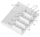
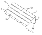
以下、本発明の実施の形態における商品陳列補助台を図1〜図14に基づいて詳述する。図1は本発明の実施の形態である商品陳列補助台を示す斜視図、図2〜図5は図1の商品陳列補助台の1構成要素の補助台を示す斜視図である。図面において、商品陳列補助台1は、商品陳列面に設置して商品の陳列状態を整えるためのもであって、片面に複数の溝2を所定の間隔且つ平行に設けた棚板3と、板4を任意箇所で所定角度に折り曲げ、その角5を形成するふたつの平面のいずれかひとつの平面に直交する仮想平面が前記ふたつの平面と交わる部分61a、61bに、該仮想平面に直交する方向に前記棚板の溝に着脱自在に係止し得る係止片6を設けた補助台7と、からなるものである。
【0013】
前記棚板3は、所定の大きさを有する平板10に所定の間隔、例えば、等間隔で且つ平行に前記溝2を設けてなる。溝2の幅・深さは、前記補助台7の係止片6を係止し、また、着脱もできる程度になっている。なお、棚板3の大きさは、商品陳列場所に対応できるように任意に設定される。棚板3は商品陳列面で水平状態あるいは傾斜状態で使用される。棚板3の材質は限定が無い。
【0014】
前記補助台7は、棚板3上に複数設置して使用するものであるから、棚板3より小さい所定の大きさを有する。そして、この補助台7は、好適な実施の形態として、板4を一方の平面が他方の平面より幅広となる箇所で、鋭角(α)となるように折り曲げ、幅広側平面11と幅狭側平面12とを有し、両平面11、12を支持するリブ8がある。幅広側平面11の端に係止片6aを、幅狭側平面12の端に係止片6bを夫々設け、係止片6aは幅広側平面11に対して(180度−鋭角(α))の角度で設けられ、係止片6a、6bは互いに面間が等距離となり、前記棚板3の溝2にスムーズに係止できるようになっている。更に、この補助台7の幅広側平面11には棚板3の溝2と同じ幅寸法の1以上の溝13が所定の間隔、例えば、等間隔で且つ平行に設けられている。なお、この溝13は、図2では3列であり、各列は4分割されているから、係止片6a、6bも溝13に係止できるように4分割されている。また、補助台7は溝13を必須条件とせず、但し、この溝13が無い場合は後述する図9〜図11、図13及び図14に示す使用方法がとれなくなり、更に、幅狭側平面12に溝13を設けてもよい。
【0015】
図3は他の実施の形態の補助台7aを示すもので、図2の補助台7との相違点は、溝13aの各列が2分割構成であり、それに伴い係止片6a、6bも溝13aに係止できるように、2分割されている点にある。図4も他の実施の形態の補助台7bを示すもので、図2の補助台7との相違点は、溝13aの各列が2分割構成であるが、それに伴い係止片6a、6bも溝13aに係止できるような2分割構成ならぬ4分割構成とされている点にある。更に、図5も他の実施の形態の補助台7cを示すもので、図3の補助台7aとの相違点は、溝13aの各列毎に幅広側平面11aに小さな段差14を設けている点にある。これら補助台7a、7b、7cの他の構成は図2の補助台7と同様であり、図に符号を付してその説明を省略する。
【0016】
このように、幅広側平面11及び幅狭側平面12は、その形状は特に制限されず、例えば平板状、波状平板又は段差付き平板が挙げられる。また、溝13は、その数及び設置箇所は特に制限されず、例えば、2〜5列、2〜5分割の範囲で適宜に組み合わせたものが使用できる。
【0017】
次に、上記構成からなる商品陳列補助台1の使用方法を図面を参照して詳述する。まず、図6に示すような形態で商品陳列補助台1は使用される。すなわち、図6は、台等で棚板3を傾斜させて商品陳列面に設置して、この棚板3の溝2に補助台7、7a、7b、7c(以下、補助台7等という。)の幅広側平面11が水平となるように、補助台7等を係止し、幅狭の雛壇を多数形成し、これら多数の雛壇上に座りのよい商品15を陳列する場合である。
【0018】
次に、図7に示すような形態で商品陳列補助台1は使用される。すなわち、図7は、傾斜させて設置した棚板3の溝2に、補助台7等を図6と逆に係止し、手前の補助台7等の幅狭側平面12を商品落下防止壁とし、奥の補助台7等の幅広側平面11を商品載置面とする幅狭の雛壇を多数形成し、これら多数の雛壇上に座りの良くない商品16を陳列する場合である。
これらの図6及び図7での商品陳列補助台1の使用は最もベーッシクな使用方法である。
【0019】
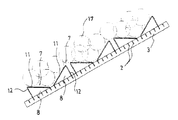
また、商品陳列補助台1は、図8に示すような形態で使用される。すなわち、図8は、棚板3を傾斜させて商品陳列面に設置して、この棚板3の溝2に補助台7等を図6及び図7における係止を交互に行い、補助台7等の幅広側平面11を水平の商品載置面及び商品の存在感・ボリュウーム感を出すための傾斜壁とする雛壇を多数形成し、これら多数の雛壇上に座りの良くない比較的大きな商品17を陳列する場合である。
【0020】
また、商品陳列補助台1は、図9に示すような形態で使用される。すなわち、図9は、棚板3を傾斜させて商品陳列面に設置して、この棚板3の溝2にこれの一番下に補助台7等を図7と同様に係止し、その上に補助台7等を図6と同様に順次係止し、更に、図6の係止による補助台7等の溝13(13a)及び棚板3の上に別の補助台7等を係止又は載置して、水平の商品載置面及び商品の存在感・ボリュウーム感を出すための傾斜壁とする雛壇を多数形成し、これら多数の雛壇上に座りのよい商品18を陳列する場合である。なお、図9では、補助台7等の3列の溝13(13a)に、別の補助台7等の係止片6aを上に行くに従って、順次ずらして係止して、両方の補助台7等の幅広側平面11により形成される商品の載置面を広くしている。
【0021】
また、商品陳列補助台1は、図10に示すような形態で使用される。すなわち、図10は、棚板3を傾斜させて商品陳列面に設置して、この棚板3の溝2にこれの一番下に補助台7等を図7と同様に係止し、その上に補助台7等を図6と同様に順次係止し、更に、図6の係止による補助台7等の係止片6a側に近い方の溝13(13a)に、別の補助台7等の係止片6bを係止して、別の補助台7等の幅広側平面11を棚板3の傾斜とほぼ同じ傾斜とし、別の補助台7等の幅広側平面11を主に商品の存在感・ボリュウーム感を出すための傾斜の商品載置面及び水平の商品載置面とし、これらの商品載置面上に座りの良い商品19を陳列する場合である。なお、別の補助台7等の上に更に別の補助台7等を係止して、3段積み以上としてもよい。
【0022】
また、図10に示す商品陳列補助台1の使用状態は、図11に示すように、図7の係止による補助台7等の係止片6a側に近い方の溝13(13a)に、別の補助台7等の係止片6bを係止しても、別の補助台7等の幅広側平面11を棚板3の傾斜とほぼ同じ傾斜とすると共に、嵩高とすることができる。
【0023】
図12は、棚板3の複数の溝2及び補助台7等の複数の溝13(13a)に、着脱自在に設けられる商品仕切り板20を示すものである。この商品仕切り板20は、板21の下面に係止片22が設けられ、板21の片端に仕切り板23が設けられてなる。係止片22は溝2及び溝13(13a)の形状に合わせて形成される。また、この商品仕切り板20は、板21の両端に仕切り板23が設けられていても何ら差し支えない。そして、この商品仕切り板20は、図13に示すように、傾斜構造の棚板3aの溝2に係止しても、補助台7a(7)の複数の溝13a(13)に係止しても、どちらでもよい。更に、図14に示すように、複数の補助台7a(7)上を3つの商品仕切り板20を使用して2つの仕切りスペースを創設する等、種々の使い方が考えられる。
以上のように、商品陳列補助台1は、商品の特性、設置場所の状況等に合わせて種々の使い勝手がある。
【0024】
以上、本発明の実施の形態を説明したが、具体的な構成はこれに限定されず、本発明の要旨を逸脱しない範囲での変更、追加は本発明の範囲内である。
【0025】
【発明の効果】
以上詳述したように、請求項1及び請求項2の発明によれば、棚板を台等で任意の角度に設置し、棚板の溝に複数の補助台を種々の方向に係止することで、棚板上に商品陳列に都合の良い種々の外観形状を創設でき、様々な商品陳列が可能となる。例えば、棚板上の1以上の補助台上に、更に他の1以上の補助台を何段でも係止して、積み上げることも可能であり、その分様々な商品陳列が可能となる。従って、少ない部品で、商品の多様化、頻繁に起こる模様替えに十分に対応でき、模様替えの度に不用となったり、新たに購入する必要性を少なくし、かつ保管のためのスペースを減らすことができる効果がある。
【0026】
請求項3の発明によれば、角を境にして幅寸法の異なる平面が2つあるから、その分様々な商品陳列が可能となる。従って、前記発明と同様の効果を奏する他、陳列の選択肢が増え、バラエティーに富んだ商品陳列が可能となる。
【0027】
請求項4の発明によれば、棚板の複数の溝及び補助台の複数の溝に商品仕切り板を着脱自在に設け、商品の区分ができる。従って、前記発明と同様の効果を奏する他、商品の区分が確実且つ容易にできる。
【図面の簡単な説明】
【図1】本発明の実施の形態である商品陳列補助台を示す斜視図。
【図2】図1の商品陳列補助台の1構成要素の補助台を示す斜視図。
【図3】図1の商品陳列補助台の1構成要素の他の補助台を示す斜視図。
【図4】図1の商品陳列補助台の1構成要素の他の補助台を示す斜視図。
【図5】図1の商品陳列補助台の1構成要素の他の補助台を示す斜視図。
【図6】本発明の実施の形態である商品陳列補助台の使用状態を示す断面図。
【図7】本発明の実施の形態である商品陳列補助台の他の使用状態を示す断面図。
【図8】本発明の実施の形態である商品陳列補助台の他の使用状態を示す断面図。
【図9】本発明の実施の形態である商品陳列補助台の他の使用状態を示す断面図。
【図10】本発明の実施の形態である商品陳列補助台の他の使用状態を示す断面図。
【図11】本発明の実施の形態である商品陳列補助台の他の使用状態を示す断面図。
【図12】本発明の実施の形態である商品陳列補助台の1構成要素の商品仕切り板を示す斜視図。
【図13】本発明の実施の形態である商品陳列補助台の1構成要素の商品仕切り板の使用状態を示す斜視図。
【図14】本発明の実施の形態である商品陳列補助台の1構成要素の商品仕切り板の使用状態を示す斜視図。
【符号の説明】
1 商品陳列補助台
2、13、13a 溝
3、3a 棚板
4、21 板
5 角
6、6a、6b、22 係止片
7、7a、7b、7c 補助台
8 リブ
10 平板
11 幅広側平板
12 幅狭側平板
15、16、17、18、19 商品
20 商品仕切り板
23 仕切り板[0001]
BACKGROUND OF THE INVENTION
The present invention is mainly used to display products on a product display surface in a store such as a supermarket, department store, specialty store, convenience store, etc., and changes the display state on the product display surface in various ways according to the characteristics of the product. It relates to a product display auxiliary stand.
[0002]
[Prior art]
Conventionally, the simplest method for displaying products on the product display surface in supermarkets, department stores, specialty stores, convenience stores, etc. is as follows: (1) A horizontal space on the product display surface is provided with a partition. There are methods of arranging products, arranging products in box-like items, and placing the whole box-like items in a horizontal space. (2) In the horizontal space on the product display surface, especially in the bottom horizontal space, it is difficult for customers to see the product in the back, and it is difficult to pick up the product, so a stand was installed in the back and a display board was placed on it and tilted. As a display shelf, there is a method in which a partition is provided on the inclined display shelf and products are arranged for each partition, or products are arranged in a box-shaped product and placed on the display shelf that is tilted together with the box-shaped product. In addition, (3) as a product display auxiliary stand for the lowest stage of the product display surface, there is a dedicated tilt table with a platform and an inclined surface installed in advance, products can be arranged directly on the platform and the inclined surface, There is a method of arranging products and placing them on a bed or an inclined surface together with this box-shaped object. Furthermore, (4) the product display surface can be selected to be horizontal or inclined, and an angle selection type product display auxiliary table that can select an inclination angle is provided with a partition, and the product is arranged for each partition, or a box-like product. Some products are placed on the auxiliary display stand of the angle selection type together with the box-like items.
[0003]
These merchandise display methods in stores such as supermarkets often affect the sales of the merchandise, and therefore various methods can be taken in addition to the methods described above. However, the basic place is that the product is partitioned and displayed by partition plates or box-like items in various display spaces such as tilted display shelves, tilt-only and angle-selection type product display auxiliary stands with the horizontal space. Is.
[0004]
[Problems to be solved by the invention]
In the product display method described in (1) and (2) above, it is necessary to prepare partition plates and box-like items according to horizontal spaces and inclined display shelves. Even if it can not be used at all other than space and inclined display shelves, or it can be used, it cannot often be used in a product display with a strong color of appearance. For this reason, partition plates and box-like items of various shapes and sizes of the same type are required, and partition plates and box-like items that are not needed each time the pattern is changed or are newly purchased. A need arises. On the contrary, since it is assumed that there is an opportunity to use the partition plates and box-like objects that are no longer needed, there is a high probability that they cannot be discarded and stored, and a storage space for that purpose is required.
[0005]
In addition, the product display method using the (3) tilt-only and (4) horizontal / tilt angle-selection product display auxiliary stand has a platform or inclined surface installed in advance, and the angle can be selected. It is easy to handle and is advantageous because it reduces the inconveniences of the product display methods (1) and (2) described above. However, for the recent trend of product diversification and frequent redesigns due to intensifying competition, it is difficult to change the pre-installed platform and inclined surface for this tilt-only product display auxiliary stand, Even if it is an angle selection type product display auxiliary stand, even if the angle can be changed, it is difficult to give a sense of presence and volume of the product. In addition, a product display auxiliary table of an angle selection type is required. Accordingly, the same result as that of the disadvantages of the above-described merchandise display methods (1) and (2) is obtained.
[0006]
Therefore, the object of the present invention is to sufficiently cope with the diversification of products and frequent redesigns with few parts, making it unnecessary for every redesign, reducing the need for new purchases, and for storage. The object of the present invention is to provide a product display auxiliary stand that can reduce the space of the product.
[0007]
[Means for Solving the Problems]
In such a situation, the present inventor has intensively studied, and as a result, shelved with a plurality of grooves provided on one side in parallel with a predetermined interval, and the plate is bent at a predetermined angle at an arbitrary position, and at both ends in the front-rear direction. It consists of an auxiliary base provided with a locking piece that can be removably locked in the groove of the shelf board, and by fitting a plurality of auxiliary bases into the groove of the shelf board, various convenient for product display on the shelf board The present invention has been completed by discovering that it is possible to create various external shapes, display various products, and that almost no spare parts are required.
[0008]
That is, the invention of the present application is a product display auxiliary stand for setting on a product display surface to prepare a product display state, and a shelf plate provided with a plurality of grooves on one side in parallel with a predetermined interval, and an arbitrary plate The plate is bent at a predetermined angle and provided with locking pieces that can be removably locked in the groove of the shelf at both ends in the front-rear direction of the plate, and the engagement is applied to one or both of the bent planes. A plurality of grooves capable of detachably locking the stop pieces, and an auxiliary base configured to be able to lock the locking pieces of the other auxiliary bases in the grooves of the auxiliary bases, the auxiliary base grooves Is provided in parallel with each other at a predetermined interval in the width direction and is divided in each row to provide a commodity display auxiliary table.
[0009]
The invention of the present application is a product display auxiliary stand for setting on a product display surface to prepare a product display state, and a shelf plate provided with a plurality of grooves on one side in parallel with a predetermined interval, and an arbitrary plate Folded at a predetermined angle at a point, a virtual plane perpendicular to any one of the two planes forming the corner intersects with the two planes, and into the groove of the shelf plate in a direction perpendicular to the virtual plane. A locking piece that can be detachably locked is provided, and a plurality of grooves that can detachably lock the locking pieces are provided on one or both of the flat surfaces formed by bending, and the groove of the auxiliary base The auxiliary table is configured to be able to lock the locking pieces of the other auxiliary table, and the grooves of the auxiliary table are provided in parallel to each other at a predetermined interval in the width direction and divided in each row. Providing a product display auxiliary stand characterized by Than is.
[0010]
According to a third aspect of the present invention, there is provided a merchandise display auxiliary table in which one of the planes formed at the corners of the auxiliary table is wider than the other.
[0011]
Further, this application onset bright, the grooves or the auxiliary stand groove of the shelf plate, there is provided a commodity display auxiliary table, characterized by further comprising a product partition plate removably mounted.
Moreover, this invention provides the goods display auxiliary | assistant stand characterized by the said groove | channel being 2-5 rows and 2-5 divisions.
[0012]
DETAILED DESCRIPTION OF THE INVENTION
Hereinafter, the commodity display auxiliary table according to the embodiment of the present invention will be described in detail with reference to FIGS. FIG. 1 is a perspective view showing a product display auxiliary table according to an embodiment of the present invention, and FIGS. 2 to 5 are perspective views showing auxiliary components of one component of the product display auxiliary table in FIG. In the drawing, a product display
[0013]
The
[0014]
A plurality of the
[0015]
FIG. 3 shows an
[0016]
Thus, the shape of the
[0017]
Next, a method of using the commodity display
[0018]
Next, the merchandise display
The use of the commodity display
[0019]
Further, the commodity display auxiliary table 1 is used in a form as shown in FIG. That is, in FIG. 8, the
[0020]
Moreover, the merchandise display
[0021]
Moreover, the merchandise display
[0022]
10 is used in the groove 13 (13a) closer to the
[0023]
FIG. 12 shows a
As described above, the commodity display
[0024]
The embodiment of the present invention has been described above, but the specific configuration is not limited to this, and changes and additions within the scope of the present invention are within the scope of the present invention.
[0025]
【The invention's effect】
As described in detail above, according to the first and second aspects of the present invention, the shelf board is installed at an arbitrary angle with a stand or the like, and the plurality of auxiliary stands are locked in various directions in the groove of the shelf board. As a result, various external shapes that are convenient for displaying products can be created on the shelf board, and various products can be displayed. For example, it is possible to lock one or more other auxiliary platforms on one or more auxiliary platforms on the shelf board and stack them, and display various products accordingly. Therefore, it is possible to cope with the diversification of products and frequent remodeling with a small number of parts, making it unnecessary for each redesign, reducing the need for new purchases, and reducing storage space. There is an effect that can be done.
[0026]
According to the invention of
[0027]
According to the fourth aspect of the present invention, the product partition plates are detachably provided in the plurality of grooves of the shelf board and the plurality of grooves of the auxiliary table, and the products can be classified. Therefore, in addition to the same effects as the above invention, the product can be reliably and easily classified.
[Brief description of the drawings]
FIG. 1 is a perspective view showing a merchandise display auxiliary stand according to an embodiment of the present invention.
2 is a perspective view showing an auxiliary table of one component of the commodity display auxiliary table of FIG. 1; FIG.
3 is a perspective view showing another auxiliary base of one component of the commodity display auxiliary base of FIG. 1; FIG.
4 is a perspective view showing another auxiliary base of one component of the commodity display auxiliary base of FIG. 1; FIG.
5 is a perspective view showing another auxiliary base of one component of the commodity display auxiliary base of FIG. 1. FIG.
FIG. 6 is a cross-sectional view showing a usage state of the commodity display auxiliary stand according to the embodiment of the present invention.
FIG. 7 is a cross-sectional view showing another usage state of the commodity display auxiliary stand according to the embodiment of the present invention.
FIG. 8 is a cross-sectional view showing another usage state of the commodity display auxiliary stand according to the embodiment of the present invention.
FIG. 9 is a cross-sectional view showing another use state of the commodity display auxiliary stand according to the embodiment of the present invention.
FIG. 10 is a cross-sectional view showing another usage state of the commodity display auxiliary stand according to the embodiment of the present invention.
FIG. 11 is a cross-sectional view showing another use state of the commodity display auxiliary stand according to the embodiment of the present invention.
FIG. 12 is a perspective view showing a product partition plate as one component of the product display auxiliary stand according to the embodiment of the present invention.
FIG. 13 is a perspective view showing a usage state of a product partition plate as one component of the product display auxiliary stand according to the embodiment of the present invention.
FIG. 14 is a perspective view showing a usage state of a product partition plate as one component of the product display auxiliary stand according to the embodiment of the present invention.
[Explanation of symbols]
1 Product display auxiliary table 2, 13,
Claims (5)
Priority Applications (2)
| Application Number | Priority Date | Filing Date | Title |
|---|---|---|---|
| JP2000251076A JP4656704B2 (en) | 2000-08-22 | 2000-08-22 | Product display support stand |
| US09/878,342 US6629617B2 (en) | 2000-08-22 | 2001-06-12 | Commodity display auxiliary base |
Applications Claiming Priority (1)
| Application Number | Priority Date | Filing Date | Title |
|---|---|---|---|
| JP2000251076A JP4656704B2 (en) | 2000-08-22 | 2000-08-22 | Product display support stand |
Publications (2)
| Publication Number | Publication Date |
|---|---|
| JP2002058571A JP2002058571A (en) | 2002-02-26 |
| JP4656704B2 true JP4656704B2 (en) | 2011-03-23 |
Family
ID=18740540
Family Applications (1)
| Application Number | Title | Priority Date | Filing Date |
|---|---|---|---|
| JP2000251076A Expired - Lifetime JP4656704B2 (en) | 2000-08-22 | 2000-08-22 | Product display support stand |
Country Status (2)
| Country | Link |
|---|---|
| US (1) | US6629617B2 (en) |
| JP (1) | JP4656704B2 (en) |
Families Citing this family (25)
| Publication number | Priority date | Publication date | Assignee | Title |
|---|---|---|---|---|
| US7114606B2 (en) * | 2002-05-08 | 2006-10-03 | B-O-F Corporation | Selectable width track apparatus and method for a gravity fed shelving system |
| US20040074857A1 (en) * | 2002-08-19 | 2004-04-22 | Kalin Robert Grad | Modular surface-mounted organizing and display system |
| JP4514099B2 (en) * | 2003-11-27 | 2010-07-28 | 河淳株式会社 | Product display stand |
| DE20319141U1 (en) * | 2003-12-10 | 2004-02-26 | Wanzl Metallwarenfabrik Gmbh | A display stand |
| US7287652B2 (en) * | 2004-03-19 | 2007-10-30 | Target Brands, Inc. | Configurable display system and modular display arrangement for consumer electronic devices |
| JP4656873B2 (en) * | 2004-04-30 | 2011-03-23 | 河淳株式会社 | Product display stand |
| JP4656869B2 (en) * | 2004-05-11 | 2011-03-23 | 河淳株式会社 | Product display shelf |
| JP4721316B2 (en) * | 2004-07-27 | 2011-07-13 | 河淳株式会社 | Product display stand |
| JP4863621B2 (en) * | 2005-01-18 | 2012-01-25 | 扶桑産業株式会社 | Product display device |
| JP4849603B2 (en) * | 2006-03-15 | 2012-01-11 | 河淳株式会社 | Product display stand |
| JP5154096B2 (en) * | 2007-02-27 | 2013-02-27 | 株式会社岡村製作所 | Product display aids |
| JP5110577B2 (en) * | 2007-09-14 | 2012-12-26 | 河淳株式会社 | Onigiri display shelf and onigiri display method |
| JP2014150993A (en) * | 2013-02-08 | 2014-08-25 | Panasonic Corp | Open showcase |
| US9140482B2 (en) * | 2013-09-30 | 2015-09-22 | Thermo Fisher Scientific (Asheville) Llc | Removable storage basket and associated methods for storing items within a freezer |
| USD801734S1 (en) | 2014-12-01 | 2017-11-07 | Retail Space Solutions Llc | Shelf management parts |
| US10154739B2 (en) | 2013-12-02 | 2018-12-18 | Retail Space Solutions Llc | Universal merchandiser and methods relating to same |
| GB2539867A (en) * | 2015-03-10 | 2017-01-04 | Escape Fitness Ltd | Reconfigurable storage apparatus for exercise equipment |
| US10045639B2 (en) * | 2016-10-04 | 2018-08-14 | Target Brands, Inc. | Display riser assembly |
| US10959540B2 (en) | 2016-12-05 | 2021-03-30 | Retail Space Solutions Llc | Shelf management system, components thereof, and related methods |
| US9788669B1 (en) * | 2017-01-31 | 2017-10-17 | Target Brands, Inc. | Product display fixture |
| WO2018200997A1 (en) | 2017-04-27 | 2018-11-01 | Retail Space Solutions Llc | Shelf-mounted tray and methods relating to same |
| US10356931B1 (en) | 2017-05-26 | 2019-07-16 | King Slide Works Co., Ltd. | Rack mounting system |
| US10104965B1 (en) * | 2017-09-23 | 2018-10-23 | Patrick Earl Miller | Toilet paper holder mounted adjustable bathroom shelf |
| US10842300B2 (en) * | 2018-04-19 | 2020-11-24 | Carl Reid | Mountable container |
| KR102225209B1 (en) * | 2019-08-21 | 2021-03-08 | 한소라 | A tester cosmetics display stand with billboard |
Citations (3)
| Publication number | Priority date | Publication date | Assignee | Title |
|---|---|---|---|---|
| JPS553967U (en) * | 1978-06-23 | 1980-01-11 | ||
| JPH0332736U (en) * | 1989-08-08 | 1991-03-29 | ||
| JPH07163446A (en) * | 1993-12-14 | 1995-06-27 | Tooin Kk | Apparatus for displaying goods |
Family Cites Families (11)
| Publication number | Priority date | Publication date | Assignee | Title |
|---|---|---|---|---|
| US1332087A (en) * | 1919-09-18 | 1920-02-24 | Paul R Vogel | Filing-cabinet |
| US2889054A (en) * | 1956-03-16 | 1959-06-02 | William G Wheeler | Food segregating rack for refrigerator shelves |
| US3481485A (en) * | 1968-03-18 | 1969-12-02 | Zero Max Ind Inc | Adjustable shelf support device |
| US3643607A (en) * | 1968-11-29 | 1972-02-22 | James Alexander Mackenzie | Shelving components |
| US3927769A (en) * | 1974-04-29 | 1975-12-23 | Metropolitan Wire Corp | Shelf structure |
| US3986462A (en) * | 1975-05-14 | 1976-10-19 | Heft Kenneth W | Deck structure for racks |
| US4476986A (en) * | 1981-10-01 | 1984-10-16 | Atlas Paper Box Company | Easel device for display shelf |
| FR2600873A1 (en) * | 1986-07-04 | 1988-01-08 | Tchen Gilbert | Shelving partition which can be clipped and retracted onto a grid displaying food or meat products |
| FR2651981A1 (en) * | 1989-09-21 | 1991-03-22 | Stal Ind | System and strip for making a display means |
| DK565989D0 (en) * | 1989-11-13 | 1989-11-13 | Expedit As | EXHIBITION OR SALES SHELF |
| GB2276538A (en) * | 1993-01-23 | 1994-10-05 | Central Display & Merchandisin | Display tray |
-
2000
- 2000-08-22 JP JP2000251076A patent/JP4656704B2/en not_active Expired - Lifetime
-
2001
- 2001-06-12 US US09/878,342 patent/US6629617B2/en not_active Expired - Lifetime
Patent Citations (3)
| Publication number | Priority date | Publication date | Assignee | Title |
|---|---|---|---|---|
| JPS553967U (en) * | 1978-06-23 | 1980-01-11 | ||
| JPH0332736U (en) * | 1989-08-08 | 1991-03-29 | ||
| JPH07163446A (en) * | 1993-12-14 | 1995-06-27 | Tooin Kk | Apparatus for displaying goods |
Also Published As
| Publication number | Publication date |
|---|---|
| US6629617B2 (en) | 2003-10-07 |
| JP2002058571A (en) | 2002-02-26 |
| US20020024273A1 (en) | 2002-02-28 |
Similar Documents
| Publication | Publication Date | Title |
|---|---|---|
| JP4656704B2 (en) | Product display support stand | |
| JP4514099B2 (en) | Product display stand | |
| JP2013031547A (en) | Storage box-folding display stand and method of using the same | |
| JP5274856B2 (en) | Product advertising equipment | |
| JP2003144280A (en) | Block for displaying goods | |
| JP4548681B2 (en) | Product display adjustment stand | |
| JP4849603B2 (en) | Product display stand | |
| JP4024034B2 (en) | Product display stand and product display shelf | |
| JP3828749B2 (en) | Display shelf | |
| JP4653433B2 (en) | Product display stand | |
| JP3152338U (en) | Dual product display stand and double product display stand kit | |
| JP3096023U (en) | Product display stand | |
| JP4721316B2 (en) | Product display stand | |
| JP2001204603A (en) | Merchandise display stand | |
| JP2001197984A (en) | Commodities display rack for display case | |
| WO2006059396A1 (en) | Commodity display board | |
| JP2006095228A (en) | Display stand | |
| JP3124091U (en) | Product display stand | |
| JP4640884B2 (en) | Product display shelf block | |
| JP2003245175A (en) | Adjusting board for goods exhibition | |
| JP3103554U (en) | Product display stand | |
| JP3206414U (en) | Product display tools | |
| JP2002209685A (en) | Commodity shelf structure | |
| JP5165129B1 (en) | Product display stand | |
| JP2002345609A (en) | Shelf device |
Legal Events
| Date | Code | Title | Description |
|---|---|---|---|
| A621 | Written request for application examination |
Free format text: JAPANESE INTERMEDIATE CODE: A621 Effective date: 20070810 |
|
| A977 | Report on retrieval |
Free format text: JAPANESE INTERMEDIATE CODE: A971007 Effective date: 20091228 |
|
| A131 | Notification of reasons for refusal |
Free format text: JAPANESE INTERMEDIATE CODE: A131 Effective date: 20100707 |
|
| A521 | Request for written amendment filed |
Free format text: JAPANESE INTERMEDIATE CODE: A523 Effective date: 20100820 |
|
| A131 | Notification of reasons for refusal |
Free format text: JAPANESE INTERMEDIATE CODE: A131 Effective date: 20101101 |
|
| A521 | Request for written amendment filed |
Free format text: JAPANESE INTERMEDIATE CODE: A523 Effective date: 20101130 |
|
| TRDD | Decision of grant or rejection written | ||
| A01 | Written decision to grant a patent or to grant a registration (utility model) |
Free format text: JAPANESE INTERMEDIATE CODE: A01 Effective date: 20101221 |
|
| A01 | Written decision to grant a patent or to grant a registration (utility model) |
Free format text: JAPANESE INTERMEDIATE CODE: A01 |
|
| A61 | First payment of annual fees (during grant procedure) |
Free format text: JAPANESE INTERMEDIATE CODE: A61 Effective date: 20101221 |
|
| FPAY | Renewal fee payment (event date is renewal date of database) |
Free format text: PAYMENT UNTIL: 20140107 Year of fee payment: 3 |
|
| R150 | Certificate of patent or registration of utility model |
Ref document number: 4656704 Country of ref document: JP Free format text: JAPANESE INTERMEDIATE CODE: R150 Free format text: JAPANESE INTERMEDIATE CODE: R150 |
|
| R250 | Receipt of annual fees |
Free format text: JAPANESE INTERMEDIATE CODE: R250 |
|
| R250 | Receipt of annual fees |
Free format text: JAPANESE INTERMEDIATE CODE: R250 |
|
| EXPY | Cancellation because of completion of term |