JP4654028B2 - Method and system for improving vision - Google Patents
Method and system for improving vision Download PDFInfo
- Publication number
- JP4654028B2 JP4654028B2 JP2004508699A JP2004508699A JP4654028B2 JP 4654028 B2 JP4654028 B2 JP 4654028B2 JP 2004508699 A JP2004508699 A JP 2004508699A JP 2004508699 A JP2004508699 A JP 2004508699A JP 4654028 B2 JP4654028 B2 JP 4654028B2
- Authority
- JP
- Japan
- Prior art keywords
- lens
- cornea
- surface model
- reference axis
- arc
- Prior art date
- Legal status (The legal status is an assumption and is not a legal conclusion. Google has not performed a legal analysis and makes no representation as to the accuracy of the status listed.)
- Expired - Fee Related
Links
Images


Classifications
-
- A—HUMAN NECESSITIES
- A61—MEDICAL OR VETERINARY SCIENCE; HYGIENE
- A61F—FILTERS IMPLANTABLE INTO BLOOD VESSELS; PROSTHESES; DEVICES PROVIDING PATENCY TO, OR PREVENTING COLLAPSING OF, TUBULAR STRUCTURES OF THE BODY, e.g. STENTS; ORTHOPAEDIC, NURSING OR CONTRACEPTIVE DEVICES; FOMENTATION; TREATMENT OR PROTECTION OF EYES OR EARS; BANDAGES, DRESSINGS OR ABSORBENT PADS; FIRST-AID KITS
- A61F9/00—Methods or devices for treatment of the eyes; Devices for putting-in contact lenses; Devices to correct squinting; Apparatus to guide the blind; Protective devices for the eyes, carried on the body or in the hand
- A61F9/0008—Introducing ophthalmic products into the ocular cavity or retaining products therein
- A61F9/0017—Introducing ophthalmic products into the ocular cavity or retaining products therein implantable in, or in contact with, the eye, e.g. ocular inserts
-
- A—HUMAN NECESSITIES
- A61—MEDICAL OR VETERINARY SCIENCE; HYGIENE
- A61F—FILTERS IMPLANTABLE INTO BLOOD VESSELS; PROSTHESES; DEVICES PROVIDING PATENCY TO, OR PREVENTING COLLAPSING OF, TUBULAR STRUCTURES OF THE BODY, e.g. STENTS; ORTHOPAEDIC, NURSING OR CONTRACEPTIVE DEVICES; FOMENTATION; TREATMENT OR PROTECTION OF EYES OR EARS; BANDAGES, DRESSINGS OR ABSORBENT PADS; FIRST-AID KITS
- A61F9/00—Methods or devices for treatment of the eyes; Devices for putting-in contact lenses; Devices to correct squinting; Apparatus to guide the blind; Protective devices for the eyes, carried on the body or in the hand
- A61F9/007—Methods or devices for eye surgery
- A61F9/008—Methods or devices for eye surgery using laser
-
- A—HUMAN NECESSITIES
- A61—MEDICAL OR VETERINARY SCIENCE; HYGIENE
- A61B—DIAGNOSIS; SURGERY; IDENTIFICATION
- A61B3/00—Apparatus for testing the eyes; Instruments for examining the eyes
- A61B3/10—Objective types, i.e. instruments for examining the eyes independent of the patients' perceptions or reactions
- A61B3/107—Objective types, i.e. instruments for examining the eyes independent of the patients' perceptions or reactions for determining the shape or measuring the curvature of the cornea
-
- A—HUMAN NECESSITIES
- A61—MEDICAL OR VETERINARY SCIENCE; HYGIENE
- A61F—FILTERS IMPLANTABLE INTO BLOOD VESSELS; PROSTHESES; DEVICES PROVIDING PATENCY TO, OR PREVENTING COLLAPSING OF, TUBULAR STRUCTURES OF THE BODY, e.g. STENTS; ORTHOPAEDIC, NURSING OR CONTRACEPTIVE DEVICES; FOMENTATION; TREATMENT OR PROTECTION OF EYES OR EARS; BANDAGES, DRESSINGS OR ABSORBENT PADS; FIRST-AID KITS
- A61F2/00—Filters implantable into blood vessels; Prostheses, i.e. artificial substitutes or replacements for parts of the body; Appliances for connecting them with the body; Devices providing patency to, or preventing collapsing of, tubular structures of the body, e.g. stents
- A61F2/02—Prostheses implantable into the body
- A61F2/14—Eye parts, e.g. lenses, corneal implants; Implanting instruments specially adapted therefor; Artificial eyes
-
- A—HUMAN NECESSITIES
- A61—MEDICAL OR VETERINARY SCIENCE; HYGIENE
- A61F—FILTERS IMPLANTABLE INTO BLOOD VESSELS; PROSTHESES; DEVICES PROVIDING PATENCY TO, OR PREVENTING COLLAPSING OF, TUBULAR STRUCTURES OF THE BODY, e.g. STENTS; ORTHOPAEDIC, NURSING OR CONTRACEPTIVE DEVICES; FOMENTATION; TREATMENT OR PROTECTION OF EYES OR EARS; BANDAGES, DRESSINGS OR ABSORBENT PADS; FIRST-AID KITS
- A61F9/00—Methods or devices for treatment of the eyes; Devices for putting-in contact lenses; Devices to correct squinting; Apparatus to guide the blind; Protective devices for the eyes, carried on the body or in the hand
- A61F9/007—Methods or devices for eye surgery
- A61F9/008—Methods or devices for eye surgery using laser
- A61F9/00802—Methods or devices for eye surgery using laser for photoablation
- A61F9/00804—Refractive treatments
-
- A—HUMAN NECESSITIES
- A61—MEDICAL OR VETERINARY SCIENCE; HYGIENE
- A61F—FILTERS IMPLANTABLE INTO BLOOD VESSELS; PROSTHESES; DEVICES PROVIDING PATENCY TO, OR PREVENTING COLLAPSING OF, TUBULAR STRUCTURES OF THE BODY, e.g. STENTS; ORTHOPAEDIC, NURSING OR CONTRACEPTIVE DEVICES; FOMENTATION; TREATMENT OR PROTECTION OF EYES OR EARS; BANDAGES, DRESSINGS OR ABSORBENT PADS; FIRST-AID KITS
- A61F2/00—Filters implantable into blood vessels; Prostheses, i.e. artificial substitutes or replacements for parts of the body; Appliances for connecting them with the body; Devices providing patency to, or preventing collapsing of, tubular structures of the body, e.g. stents
- A61F2/02—Prostheses implantable into the body
- A61F2/14—Eye parts, e.g. lenses, corneal implants; Implanting instruments specially adapted therefor; Artificial eyes
- A61F2/145—Corneal inlays, onlays, or lenses for refractive correction
-
- A—HUMAN NECESSITIES
- A61—MEDICAL OR VETERINARY SCIENCE; HYGIENE
- A61F—FILTERS IMPLANTABLE INTO BLOOD VESSELS; PROSTHESES; DEVICES PROVIDING PATENCY TO, OR PREVENTING COLLAPSING OF, TUBULAR STRUCTURES OF THE BODY, e.g. STENTS; ORTHOPAEDIC, NURSING OR CONTRACEPTIVE DEVICES; FOMENTATION; TREATMENT OR PROTECTION OF EYES OR EARS; BANDAGES, DRESSINGS OR ABSORBENT PADS; FIRST-AID KITS
- A61F2/00—Filters implantable into blood vessels; Prostheses, i.e. artificial substitutes or replacements for parts of the body; Appliances for connecting them with the body; Devices providing patency to, or preventing collapsing of, tubular structures of the body, e.g. stents
- A61F2/02—Prostheses implantable into the body
- A61F2/14—Eye parts, e.g. lenses, corneal implants; Implanting instruments specially adapted therefor; Artificial eyes
- A61F2/16—Intraocular lenses
-
- A—HUMAN NECESSITIES
- A61—MEDICAL OR VETERINARY SCIENCE; HYGIENE
- A61F—FILTERS IMPLANTABLE INTO BLOOD VESSELS; PROSTHESES; DEVICES PROVIDING PATENCY TO, OR PREVENTING COLLAPSING OF, TUBULAR STRUCTURES OF THE BODY, e.g. STENTS; ORTHOPAEDIC, NURSING OR CONTRACEPTIVE DEVICES; FOMENTATION; TREATMENT OR PROTECTION OF EYES OR EARS; BANDAGES, DRESSINGS OR ABSORBENT PADS; FIRST-AID KITS
- A61F9/00—Methods or devices for treatment of the eyes; Devices for putting-in contact lenses; Devices to correct squinting; Apparatus to guide the blind; Protective devices for the eyes, carried on the body or in the hand
- A61F9/007—Methods or devices for eye surgery
- A61F9/008—Methods or devices for eye surgery using laser
- A61F2009/00861—Methods or devices for eye surgery using laser adapted for treatment at a particular location
- A61F2009/00872—Cornea
-
- A—HUMAN NECESSITIES
- A61—MEDICAL OR VETERINARY SCIENCE; HYGIENE
- A61F—FILTERS IMPLANTABLE INTO BLOOD VESSELS; PROSTHESES; DEVICES PROVIDING PATENCY TO, OR PREVENTING COLLAPSING OF, TUBULAR STRUCTURES OF THE BODY, e.g. STENTS; ORTHOPAEDIC, NURSING OR CONTRACEPTIVE DEVICES; FOMENTATION; TREATMENT OR PROTECTION OF EYES OR EARS; BANDAGES, DRESSINGS OR ABSORBENT PADS; FIRST-AID KITS
- A61F9/00—Methods or devices for treatment of the eyes; Devices for putting-in contact lenses; Devices to correct squinting; Apparatus to guide the blind; Protective devices for the eyes, carried on the body or in the hand
- A61F9/007—Methods or devices for eye surgery
- A61F9/008—Methods or devices for eye surgery using laser
- A61F2009/00885—Methods or devices for eye surgery using laser for treating a particular disease
- A61F2009/00895—Presbyopia
-
- A—HUMAN NECESSITIES
- A61—MEDICAL OR VETERINARY SCIENCE; HYGIENE
- A61F—FILTERS IMPLANTABLE INTO BLOOD VESSELS; PROSTHESES; DEVICES PROVIDING PATENCY TO, OR PREVENTING COLLAPSING OF, TUBULAR STRUCTURES OF THE BODY, e.g. STENTS; ORTHOPAEDIC, NURSING OR CONTRACEPTIVE DEVICES; FOMENTATION; TREATMENT OR PROTECTION OF EYES OR EARS; BANDAGES, DRESSINGS OR ABSORBENT PADS; FIRST-AID KITS
- A61F9/00—Methods or devices for treatment of the eyes; Devices for putting-in contact lenses; Devices to correct squinting; Apparatus to guide the blind; Protective devices for the eyes, carried on the body or in the hand
- A61F9/007—Methods or devices for eye surgery
- A61F9/013—Instruments for compensation of ocular refraction ; Instruments for use in cornea removal, for reshaping or performing incisions in the cornea
Description
本出願は2003年6月3日に出願した米国仮出願第60/385,601号および2003年2月21日に出願した米国仮出願第60/449,029号の利益を主張するものであり、全体を参照して本願に組み込む。 This application claims the benefit of US Provisional Application No. 60 / 385,601 filed Jun. 3, 2003 and US Provisional Application No. 60 / 449,029 filed Feb. 21, 2003. , Incorporated herein by reference in its entirety.
本発明は、眼の視力を診断および改善する方法ならびにシステムに関する。 The present invention relates to methods and systems for diagnosing and improving eye vision.
人間の視力における最も一般的な欠陥は、眼において適切に焦点を結ぶことができないことに起因する。例えば、近視は眼において網膜ではなく、その前方に焦点を結ぶことにより生じ、遠視は眼において網膜を超えて焦点を結ぶことにより生じ、そして乱視は、眼が鮮明な焦点を結ばず不鮮明な領域を作ることにより生じる。眼科医は直交長軸と短軸とによって画定される楕円体の一部として角膜のモデルを作る。現在の視力矯正の外科手術は、通常、角膜の形状をより球面状にさせながらその表面曲率を増加または減少させるか、またはそれを「平均的な」楕円に合わせるか、または波面解析に基づく矯正を行うようにしている。 The most common defect in human vision results from the inability to focus properly on the eye. For example, myopia is caused by focusing in front of the eye, not the retina, hyperopia is caused by focusing beyond the retina in the eye, and astigmatism is a region in which the eye is not clearly focused and is blurred. It is caused by making. An ophthalmologist makes a model of the cornea as part of an ellipsoid defined by orthogonal long and short axes. Current vision correction surgery usually increases or decreases its surface curvature while making the cornea more spherical, or fits it to an “average” ellipse, or correction based on wavefront analysis Like to do.
角膜切除手術のような現代の角膜処置に関連し、臨床適用、ならびにコンタクトレンズの設計および製造に、高解像度のカメラが使用され、角膜表面上の離散データポイントのデジタル化配列を得ている。角膜の写像に利用可能なシステムおよびカメラの1つに、パービジョンシステムズ社のパー角膜トポグラフィシステム(PAR CTS)がある。PAR CTSは3次元デカルト空間の角膜表面トポロジー、すなわち奥行き(Z)座標に加え、XおよびY座標に沿って写像し、次に開業医の外科手術の計画、コンタクトレンズの設計に用いられる「視線」の位置を探す。 In connection with modern corneal procedures such as keratotomy, high-resolution cameras are used in clinical applications and in contact lens design and manufacture to obtain digitized arrays of discrete data points on the corneal surface. One of the systems and cameras available for corneal mapping is Pervision Systems' Per Corneal Topography System (PAR CTS). The PAR CTS maps along the corneal surface topology in three-dimensional Cartesian space, ie depth (Z) coordinates, along the X and Y coordinates, and is then used to plan the surgeon's surgery and contact lens design Find the location of.
「視線」は固視点から入射瞳の中心への直線線分である。非特許文献1に、より詳細に記述されているように、固視点から入射瞳上の一点に向かって導かれる光線は、角膜および眼房水によって屈折し、実瞳孔の対応する点を通過し、最後に網膜に達する。 The “line of sight” is a straight line segment from the fixed viewpoint to the center of the entrance pupil. As described in more detail in Non-Patent Document 1, a light beam guided from a fixed point toward a point on the entrance pupil is refracted by the cornea and aqueous humor and passes through a corresponding point of the real pupil. And finally reach the retina.
視線が角膜表面と交差する角膜上の点は、角膜の「光学的中心」即ち「サイティングセンタ」である。それは普通、光屈折角膜切除術で切除される領域の中心を表す屈折矯正手術のための主要な基準点である。視線は従来、角膜切除手術を管理するレーザ制御システムのプログラムに組み込まれてきた。しかしながら、外科医の中には瞳孔軸を基準線として使用することを好むものもいる。経験がある開業医らは、サイティングセンタの位置を探す様々な技術を用いてきた。ある一つの技術では、瞳孔(「光学的」)軸に対するサイティングセンタの位置を計算するために、角度λが使用される。非特許文献1によれば、角度κおよびλについて詳細な説明がある。その全文を記述する本願の参考文献に開示内容が組み込まれている。 The point on the cornea where the line of sight intersects the corneal surface is the “optical center” or “sitting center” of the cornea. It is usually the primary reference point for refractive surgery that represents the center of the area that is removed by photorefractive keratotomy. Line of sight has traditionally been incorporated into programs in laser control systems that manage keratotomy surgery. However, some surgeons prefer to use the pupil axis as a reference line. Experienced medical practitioners have used a variety of techniques to locate sighting centers. In one technique, the angle λ is used to calculate the position of the sighting center relative to the pupil (“optical”) axis. According to Non-Patent Document 1, there are detailed descriptions of the angles κ and λ. The disclosure is incorporated in the references of this application which describe the full text.
現代の角膜切除処置においては、角膜表面の一部、または弁の下の表面が切除される。集められた隆起データは、レーザ等の切除装置の指示に用いて、切除ゾーン内で視線(または、「平均的な」楕円、または波面指紋)まわりの適切な半径の球面状表面に、より接近して角膜表面を選択的に切除できる。処置用の基準線として視線を使用することにより近視を低減でき、そうでなければ術前の機能障害または視覚異常を矯正することができる。しかしながら、現在の乱視を悪化させ、または治療した眼に乱視または球面収差を引き起こす恐れのあるさらに異常な形の角膜になる可能性がある。このことは、その後のどのような視力矯正対策をも複雑なものにする。また、引き起こされる如何なる実質上の表面異常も、そのいずれもが視力に悪影響を与え得る瘢痕組織の進行、または涙沈積の局所的蓄積を引き起こすことがある。 In modern keratotomy procedures, a portion of the corneal surface or the surface under the valve is removed. Collected ridge data can be used to direct an ablation device such as a laser to get closer to a spherical surface of the appropriate radius around the line of sight (or “average” ellipse, or wavefront fingerprint) within the ablation zone Thus, the corneal surface can be selectively excised. By using gaze as a treatment reference line, myopia can be reduced, otherwise preoperative dysfunction or visual abnormalities can be corrected. However, current astigmatism can be exacerbated or can result in a more abnormally shaped cornea that can cause astigmatism or spherical aberration in the treated eye. This complicates any subsequent vision correction measures. Also, any substantial surface abnormality that is caused can cause the progression of scar tissue, or the local accumulation of tear deposits, any of which can adversely affect vision.
視線または瞳孔軸の基準軸としての使用には、角膜は眼の半径に沿って伸長する軸の周りで対称であるという仮定がこめられている。しかしながら、角膜は「非対称な非球面」の表面である。「非球面」は、どの角膜「経線」に沿う曲率半径も一定ではない(「経線」は角膜表面と瞳孔軸を含む平面との交差によって成形される曲線として考えることができる)ということを意味する。実際、角膜の曲率は、幾何学的中心から外周に向かって段々と平坦化する傾向がある。「非対称な」は、角膜の経線がそれらの中心まわりで対称性を示さないということを意味する。角膜が非球面および/または非対称である度合いは患者によって異なると同時に同一人間でも眼によって変わる。 The use of the line of sight or pupil axis as a reference axis assumes the assumption that the cornea is symmetric about an axis extending along the radius of the eye. However, the cornea is an “asymmetric aspheric” surface. “Aspherical” means that the radius of curvature along any cornea “meridian” is not constant (the “meridian” can be thought of as a curve shaped by the intersection of the corneal surface and the plane containing the pupil axis). To do. In fact, the curvature of the cornea tends to flatten gradually from the geometric center toward the outer periphery. “Asymmetric” means that the corneal meridians do not exhibit symmetry about their centers. The degree to which the cornea is aspheric and / or asymmetrical varies from patient to patient and also from eye to eye in the same person.
本特許出願の譲受人に譲渡された特許文献1に開示された方法に従って分析された臨床測定結果から、角膜が眼に対して傾斜、通常、前方および下方への傾斜を示すということが判明した。この傾斜は6°にもなり、平均して1°〜3°の間である。従って、基準軸としての視線または瞳孔軸を利用する角膜切除手術は、角膜がある部分を切除し過ぎたり角膜の他の部分の切除が足りない傾向がある。同時にそれは、切除された角膜と眼の残部との間の幾何学的関係を変化させる。こうして角膜の傾斜を考慮に入れない切除処置はいずれも角膜の望ましい成形ができる可能性は低く、従ってその効果を予測できない。同様に、傾斜を考慮に入れないコンタクトレンズの設計(または、視力の改善に用いられる他のあらゆるレンズ)は最適の結果を得られないことになる。 From clinical measurements analyzed according to the method disclosed in US Pat. No. 6,057,034 assigned to the assignee of the present patent application, it has been found that the cornea exhibits tilt relative to the eye, typically forward and downward tilt. . This slope can be as much as 6 °, on average between 1 ° and 3 °. Therefore, corneal ablation surgery using the line of sight or the pupil axis as a reference axis tends to excise too much of the part with the cornea or lack of excision of the other part of the cornea. At the same time, it changes the geometric relationship between the resected cornea and the rest of the eye. Thus, any ablation procedure that does not take into account the inclination of the cornea is unlikely to produce the desired shape of the cornea, and therefore the effect cannot be predicted. Similarly, contact lens designs that do not take into account tilt (or any other lens used to improve vision) will not achieve optimal results.
特許文献1の方法による臨床測定結果の分析から、PAR CTSの基準平面から最も離れた角膜の表面上の点(以下、頂点と称す)が角膜の中心または瞳孔の中心よりも角膜切除用の基準点として遥かに有効であることが判明した。特に、特許文献1に論証されるように、頂点を通過する軸周りのレーザ切除は、瞳孔軸のような眼の中心に近い軸周りで実施される同じ手術よりも、非常に規則的に成形された角膜を作り、実質的に角膜の除去量がより少なくなる。
角膜切除手術に角膜傾斜を組み入れて頂点を利用することは、改善された一貫した結果をもたらすが、予測不可能性は依然として極めて高い。例えば、臨床測定値の分析により、術後の角膜が角膜切除手術の直後いくつかの眼において形状変化を始める、ということが判っている。こうして従来の手術により最も普通に作られるタイプの殆ど完全な球面の術後の角膜は、時間と共に非球面、非対称の形状に戻る。 Incorporating a corneal slope into a corneal ablation procedure and taking advantage of the apex provides improved and consistent results, but the unpredictability is still very high. For example, analysis of clinical measurements has shown that post-operative corneas begin to change shape in some eyes immediately after keratotomy. Thus, an almost perfect spherical post-operative cornea of the type most commonly made by conventional surgery returns to an aspheric, asymmetric shape over time.
本発明者らは、角膜切除手術が、偏狭な手法のため、決して最適な成功および予測性を有しているとは思っていない。滑らかな球面の角膜(即ち、予め考えた楕円形のもの)が視力を最も効果的にするという見込みで、角膜の形に専念することが一般通例となっている。しかしながら、人間の眼は、その全てが視力に影響を及ぼす角膜の前部表面(例えば、後部角膜表面、水晶体、および眼房水)以外に、多数の光学的構成要素を含む複雑なシステムである。さらに眼の機械的環境も無視できない。例えば、最近の臨床測定結果の分析によると、瞼は角膜に相当大きな圧力を与えており、これが角膜の上部の縁近くで、角膜を平坦にさせ、下部の縁近くで、窪みを成形するいうことが判明している。眼の機械的環境がその形状の大部分を占めると信じられている。このことは、また、完全球面の術後の角膜が必ず非球面、非対称の形状に戻る理由を説明している。 We do not believe that keratotomy has optimal success and predictability due to its narrow approach. It is common practice to concentrate on the shape of the cornea, with the expectation that a smooth spherical cornea (i.e., an elliptical shape previously conceived) will provide the best visual acuity. However, the human eye is a complex system that includes a number of optical components other than the anterior surface of the cornea (eg, the posterior corneal surface, the lens, and the aqueous humor), all of which affect vision. . Furthermore, the mechanical environment of the eye cannot be ignored. For example, according to recent analysis of clinical measurements, wrinkles are exerting considerable pressure on the cornea, which causes the cornea to be flat near the upper edge of the cornea and to form a depression near the lower edge. It has been found. It is believed that the mechanical environment of the eye occupies most of its shape. This also explains why a fully spherical post-operative cornea always returns to an aspheric, asymmetric shape.
全体を参考として本願の中にその開示を引用した本出願人らの米国特許出願第09/6,416,179号によれば、眼の角膜切除手術は、角膜の自然な形状、または眼の残部に対するその向きを妨げず、必要な視力矯正を実現するために、その表面曲率を適切に変える方法で、眼の角膜切除手術が行われる。精度が異なる度合いで角膜を形作る3つの好ましい実施形態が記述されている。コンタクトレンズ設計の際のレンズの形状選定に用いる同様の手法も開示している。 According to Applicants' U.S. patent application Ser. No. 09 / 6,416,179, the disclosure of which is incorporated herein by reference in its entirety, the corneal resection surgery of the eye involves the natural shape of the cornea, or the ocular In order to achieve the required vision correction without hindering its orientation with respect to the rest, an eye keratotomy is performed by a method that appropriately changes its surface curvature. Three preferred embodiments have been described that shape the cornea to varying degrees of accuracy. A similar technique used for selecting the shape of a lens when designing a contact lens is also disclosed.
本発明に従って改良した特許文献1の方法による臨床測定結果の分析から、波面分析、プラシド角膜計技術など周知の角膜分析技術に内在する人間の眼の構造についてなされた仮説についての問題を提起する。特に、他の光学系とは違い、角膜の中央部分(例えば、直径3mmまで)は、その焦点を結ぶ能力において角膜のかなり大きな部分(例えば、直径7mmまで)に比べ光学的に優れていないことが分かっている。角膜の中央部分は大量の焦点分散を示す。即ち、角膜の異なる領域は焦軸上の同じ点に焦点を結ばない。実際、軸上に焦点を結ぶことさえしない。角膜の中央部分では、この違いが最も顕著になり、中央からの直径が増加することに伴って大幅に低下する。 From the analysis of the clinical measurement results by the method of Patent Document 1 improved according to the present invention, the problem about the hypothesis made about the structure of the human eye inherent in well-known corneal analysis techniques such as wavefront analysis and placidokeratometer technique is raised. In particular, unlike other optical systems, the central part of the cornea (eg up to 3 mm in diameter) is not optically superior to the much larger part of the cornea (eg up to 7 mm in diameter) in its ability to focus. I know. The central part of the cornea shows a large amount of focal dispersion. That is, different areas of the cornea do not focus on the same point on the focal axis. In fact, it doesn't even focus on the axis. In the central part of the cornea, this difference is most noticeable and decreases significantly with increasing diameter from the center.
本発明によれば、異なる領域が実質的に同じ軸に焦点を結ぶように角膜の焦点を調整することによって視力の改善は可能である。これは、角膜の成形(例えば、切除により)、または、適切な補正レンズの適用により実現可能である。いずれの場合も、角膜の中央部を修正することによって、さらに外へ向かう部分を修正するよりも、焦点分散の修正にさらに大きな影響を与えるはずである。しかしながら、調整は双方に対してなされる方が好ましい。 According to the present invention, visual acuity can be improved by adjusting the focus of the cornea so that different regions are focused on substantially the same axis. This can be achieved by shaping the cornea (eg by ablation) or by applying an appropriate correction lens. In either case, modifying the central part of the cornea should have a greater impact on the correction of the focal dispersion than modifying the further outward part. However, it is preferable to make adjustments for both.
本発明の上述の簡単な説明ならびに他の目的、特徴および利点は添付図面を参照することによって、好ましい実施形態の以下の詳細な説明よりさらに完全に理解される。 The foregoing brief description of the invention, as well as other objects, features, and advantages, will be more fully understood from the following detailed description of the preferred embodiments, with reference to the accompanying drawings.
本発明による角膜のレーザ切除およびコンタクトレンズ成形を実現するためのプロセスが、図1のブロック図に示されている。このプロセスは、角膜画像捕捉システム610、隆起分析プログラム620、コンピュータ援用設計システム630、コマンドプロセッサ640および角膜成形システム650を用いる。角膜画像捕捉システム610は隆起分析プログラム620と共同して患者の角膜の3次元トポグラフィマップを作成する。コンピュータ援用設計システム630は、表面モデルを作るために角膜のトポグラフィデータを編集または修正するために用いられ、モデルに関するデータはコマンドプロセッサ640を経由して角膜成形システム650へ送られる。コマンドプロセッサ640は、コンピュータ援用設計システム630から送られてきた成形される角膜表面を記述したトポグラフィデータを用いて、角膜/レンズ成形システム650が必要とする一連の命令/制御信号を生成する。角膜/レンズ成形システム650は、コマンドプロセッサ640から送られてきた、その3次元方向の動きを記述する一連の命令(いずれの座標系を用いてもよい。例えばデカルト、放射状または球面座標)を受け取って、角膜を成形、またはコンタクトレンズを機械加工する(例えば、旋盤)。
A process for realizing laser ablation of the cornea and contact lens molding according to the present invention is illustrated in the block diagram of FIG. This process uses a corneal
角膜画像捕捉システム610および隆起分析プログラム620は、パービジョンシステムズ社から入手が可能なPAR(登録商標)角膜トポグラフィシステム(「PAR(登録商標)システム」)の部品であることが好ましい。隆起分析プログラム620は、例えばIBM(商標)互換PCのようなプロセッサによって実行されるソフトウェアプログラムの一種である。プログラム620はシステム610によって測定された角膜表面上の複数の標本点の各々について、3次元要素(眼の内部の基準平面から隔たった距離を表すZ座標)を生成する。各点は、基準平面に写像されたそのX−Y座標により画定され、そのZ軸は点の輝度から決定される。各点の隆起、即ち、Z座標を算出する一つの方法は、患者の角膜14から測定されたX−Y座標および輝度値と、既知の隆起を有する基準平面の座標および輝度、例えば既知の半径の球面とを比較する方法である。基準値は予め入力しておくことができる。
The corneal
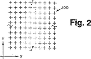
隆起分析プログラム620の最終出力は、角膜14の表面の点群データとして知られる多数の標本点についてのX−Y−Z座標である。角膜表面上の点の位置および隆起に関する情報を提供するX、Y、Z座標角膜データを、必要とされる精度でもって生成できる如何なる方法をも使用できるということは当業者には明白である。好ましい実施形態では、X−Y面に図示されるように、X−Y平面に約1500個の点が約200ミクロン間隔で投影されるように、格子パターン状に配置されている。
The final output of the
隆起分析プログラム620から出力されたX−Y−Z座標データは、種々の公知の機械固有の形式にフォーマット可能である。好ましい実施形態において、データは、通常、データのアプリケーション間転送に用いられる業界標準形式−データ交換ファイル(DXF)形式にフォーマットされる。DXFファイルは、殆どのコンピュータ援用設計システムで読み込むことができるASCIIデータファイルの一種である。
The XYZ coordinate data output from the
図2および図3を参照すると、点群データ100は、Z軸(すなわちX−Y平面に投影されるように)に沿って基準平面を眺めたとき見えてくるように描かれている。各点は患者の角膜上の特定位置に対応する。データは普通、角膜の略10mm×10mmの有界領域、すなわち作業領域から生成されるため、50行ものデータポイントがあることになる。患者の角膜表面のトポグラフィをモデリングした、またはそれに適合する表面108(図4参照)は、コンピュータ援用設計システム630によって、隆起分析プログラムで生成されたデータポイントをもとに生成される。好ましい実施形態において、コンピュータ援用設計システム630はアリゾナ州スコッツデールのマニュファクチャリング・コンサルティング・サービス(Manufacturing Consulting Services)から入手可能なAnvil5000(商標)プログラムである。
Referring to FIGS. 2 and 3, the
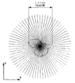
角膜一致表面108は、点群データ100の複数のデータポイントによってそれぞれが画定される複数のスプライン102を最初に生成することによって成形されることが好ましい。複数のデータポイント(即ち、節目の点)と交差するスプラインの生成自体は当業者に知られており、データを一旦入力すれば、Anvil5000(商標)プログラムによって生成できる。表面モデルの生成に関する詳細については、参考文献として本願に開示されている特許文献1を参照できる。好ましい実施形態において、周知の非一様有理Bスプライン式がスプライン生成に用いられるが、スプラインについての他の公知の数式、例えば3次スプライン式、または一様有理Bスプライン式でも生成できる可能性もある。図3に示されるような好ましい実施形態において、各スプライン102はX軸およびZ軸に平行な平面にあり、図3の点群データ100からの点の行を含む。
The corneal
次に、走査された眼の角膜表面に一致する表面108が、スプライン102から生成される。複数のスプライン102から表面を成形するために使用できる多数の公知の数式がある。好ましい実施形態において、公知のナーブ面方程式が、スプライン102から角膜表面を成形するために用いられる。この実施例において、眼の走査領域は、略10mm×10mm四方であるので、はぼ50本のスプライン102が作られる。図3に示されるように、除膜表面区分104が隣接するスプライン数本ずつ(例えば5本)について作られる。隣接する除膜表面区分104は、共通の境界スプラインを共有する。こうして約10個の除膜表面区分が点群データから生成され、次に、当業者には周知の方法でAnvil5000(商標)プログラムによって一体化され、一つの複合表面108を成形する。
A
ナーブ面方程式を用いて、数学的に表面を成形するので、原データポイントも、スプライン102の節目のポイントも、表面108上にあるとは限らない。しかしながら、表面108は、既定の公差範囲内でこれらのポイントを推定したものである。
Since the surface is mathematically shaped using the Nerve surface equation, neither the original data points nor the knot points of the
次に、作成した角膜一致表面108上の頂点(すなわちZ値が最大であるポイント)を決定する。次に、所定の直径の円筒106を、Z軸に平行かつ頂点を通る軸に沿った角膜一致表面108に投影する。円筒106の直径は4mm〜7mm、典型的には6mmであることが好ましく、円筒106と表面108との交差によって成形される閉曲線は、X−Y平面において円106′として投影する。この一致表面108上において閉曲線は角膜の作業領域の外縁部26を画定する。角膜は頂点周辺で最も対称的でありかつ球面状であるので、このポイントにおいて光学特性が最適となる。
Next, the vertex (that is, the point with the maximum Z value) on the created
外縁部26は、測定した角膜データに基づいて角膜表面が成形できるように点群データ内に収まっている必要がある。次に、コンピュータ援用設計システム630は、点群データに対して標準設定の円106′(X−Y平面において)を、例えば、モニタ画面上に表示することができるので、オペレータは、円106′が点群データ内に入っていることを確認できる。更に、システム630は、円106′が点群データ100内部に入っているかどうかを判断し、それが点群データ100内に完全に収まっていない場合、円106′が角膜データ点群データ100内に収まるように円を操作し(すなわち中心点を移動させ、および/または円の半径を変更する)、使用者に警告する設定にすることもできる。最悪の場合、走査した眼からのデータが不十分なら、角膜の作業領域を点群データ内で適切に適合させるため、再び走査する必要がある。あるいは、点群データの領域をより広くすることもできる。
The outer edge portion 26 needs to be included in the point cloud data so that the corneal surface can be formed based on the measured corneal data. Next, the computer-aided
円106′はX−Y平面で見た場合(即ち、Z軸に沿って見たとき)、単なる円であることが理解される。周縁26は、実際には、略楕円であり、基準平面に対して傾斜している平面上にある。頂点を通り抜ける傾斜した平面に垂直な直線を、「ローカルZ軸」、または「傾斜軸」とし、基準平面に対する傾斜平面の傾斜は、角膜の作業領域の傾斜角度とする。 Circle 106 'is understood to be a simple circle when viewed in the XY plane (i.e., viewed along the Z axis). The peripheral edge 26 is actually substantially oval and lies on a plane that is inclined with respect to the reference plane. A straight line perpendicular to the inclined plane passing through the apex is defined as “local Z axis” or “inclined axis”, and the inclination of the inclined plane with respect to the reference plane is the inclination angle of the work area of the cornea.
角膜の厚さは、約600μmである。角膜切除処置の多くは、一般的に用いられるタイプのレーザで傷跡を残す危険性は実質的にないので、深さ100μm未満の角膜が切除される。深さが100μmを超えると、傷跡を残す危険性は増大する。例えば、深さ120μmでの切除は、傷跡を残すことが知られている。しかしながら、より深く切除しても、レーザ処理の前、またはそれと同時の薬物療法によって傷跡が残る危険性を低減できる可能性がある。角膜起伏の大きさは、山の頂上から谷の窪みまで一般に約15〜20ミクロンであり、略30ミクロンである。 The thickness of the cornea is about 600 μm. Many corneal ablation procedures have virtually no risk of leaving scars with commonly used types of lasers, so corneas less than 100 μm deep are excised. When the depth exceeds 100 μm, the risk of leaving scars increases. For example, resection at a depth of 120 μm is known to leave a scar. However, even deeper excisions may reduce the risk of scarring before or after laser treatment. The size of the corneal undulation is generally about 15 to 20 microns from the top of the mountain to the valley recess, and is about 30 microns.
本発明により行われる外科手術、および製造される光学レンズには、「屈折検査」で確立した必要な修正に従って、患者の視力を矯正することが要求される。この検査を実施する場合、患者は「フォロプタ」と呼ばれる特殊な装置が取り付けられた椅子に座り、「フォロプタ」を通して患者は約20フィート離れた視力検査表を見る。患者がフォロプタを覗き込みながら、医師は異なる強さのレンズを視界中で操作し、特定のレンズを所定の場所に置きながら、その都度患者に検査表がより鮮明に、またはより不鮮明に見えるかどうかを尋ねる。特に、医師は2つの直交軸についての強度または視度矯正、および視線に沿ったZ軸周りのそれらの軸の回転度合いを変更することができる。医師は患者が最適の視力が得られるまで、これら3つのパラメータを修正し続ける。屈折検査の結果は、普通「a、b、c°」形式で与えられ、ここで、「a」は第1軸における視度矯正、「b」は第2直交軸で要求される追加の視度矯正、および「c°」は水平に対する第1の軸の回転角度である。この形式の情報は各眼に与えられ、眼鏡レンズ1組を研磨するために直ぐに役立つ。 Surgery performed according to the present invention, and the optical lenses produced, are required to correct the patient's vision according to the necessary modifications established in the “refractive examination”. When performing this test, the patient sits in a chair fitted with a special device called a “phoropter” through which the patient sees a vision test table about 20 feet away. As the patient looks into the phoropter, the doctor manipulates lenses of different strengths in the field of view, and places the particular lens in place while the patient sees the exam table more clearly or less clearly Ask about it. In particular, the physician can change the intensity or diopter correction about two orthogonal axes and the degree of rotation of those axes about the Z axis along the line of sight. The physician will continue to modify these three parameters until the patient obtains optimal vision. The result of the refraction test is usually given in the form “a, b, c °”, where “a” is diopter correction in the first axis and “b” is the additional view required in the second orthogonal axis. Degree correction, and “c °” is the rotation angle of the first axis relative to the horizontal. This type of information is given to each eye and is immediately useful for polishing a set of spectacle lenses.
本発明の目的に関し、屈折検査の一変型を実施することが好ましい。この屈折検査の一変型について、眼科医は、フォロプタを一連の等間隔角度、例えば水平から15°毎に調節し、各角度において最適の屈折を得ている。通常、測定される角度が増えるほど、結果はより良くなるが、屈折検査には時間を要するので、全部で12回の読取値となる15°刻みが妥当な数であると思われる。屈折検査の一変型を使用する方法は、以下に詳細に記述する。 For the purposes of the present invention, it is preferable to implement a variation of the refraction test. For a variation of this refraction test, the ophthalmologist adjusts the phoropter at a series of equally spaced angles, eg, every 15 ° from the horizontal, to obtain optimal refraction at each angle. In general, the more the angle measured, the better the results, but the refraction inspection takes time, so a 15 ° increment that gives a total of 12 readings seems to be a reasonable number. The method of using a variation of the refraction test is described in detail below.
表面108上の特性曲線を生成する有用な技術を以下に記述する。ローカルZ軸を含む平面110が構成される(図4参照)。平面110と表面108との間の交差は、第1の特性曲線112を画定する。次に、平面110は、ローカルZ軸の周囲で、例えば5°刻みの反時計回りで、線114で表されるように回転させられ、表面108とのその交差点は図4に破線で図示される第2特性曲線116を画定する。このプロセスは、特性曲線一組(経線)を作るために、ローカルZ軸の周囲に固定回転増分で、例えば、5°毎に、この場合72回(360°÷5°)、平面110が360°掃引するまで続く。
A useful technique for generating a characteristic curve on the
次に、最も良く適合する球面(円形の)の弧により各特性曲線を評価する。この評価を行う方法の一つは、各曲線(例えば、曲線が輪郭線106′に触れる点、頂点、および、ローカルZ軸に沿って透視した場合これらの2点間の途中の点)について3つの公知の点を通過する円弧を単に選定することである。一旦、球面の弧が成形されると、円弧で表される角膜部分の焦点はその弧の中心によって評価できる。円弧の中心を探索する技術は周知である。次に、その結果として一揃いの円弧の中心は焦点分散を表現する。 Each characteristic curve is then evaluated with the best-fit spherical (circular) arc. One way to perform this evaluation is for each curve (eg, the point where the curve touches the contour line 106 ', the vertex, and the point halfway between these two points when viewed along the local Z axis). Simply selecting an arc passing through two known points. Once a spherical arc is formed, the focal point of the corneal portion represented by the arc can be evaluated by the center of the arc. Techniques for searching for the center of an arc are well known. As a result, the center of the set of arcs represents the focal dispersion.
図示の目的から、前の処置は20/15未矯正視力を有する患者の角膜モデルに関して行われた。これらの結果は非典型的ではない。 For purposes of illustration, the previous procedure was performed on a corneal model of a patient with 20/15 uncorrected vision. These results are not atypical.
図5は、直径3.0mmまで延びた角膜のその部分の、ローカルZ軸に沿った、焦点分散線図である。この場合、焦点は、ローカルZ軸に沿って、7.06mmの地点から結び始め、さらに6.91mmまで延びている。図6は、直径3mm以内における放射分散が1.2mmであることを示す。同様に、図7は、角膜の直径5mm部分の軸方向焦点分散が8.99mmの地点で始まり、さらに、1.69mm延びていることを示す。図8に示すように、角膜の同じ部分の放射分散は0.49mmである。図9は、直径7mmにおける軸方向焦点分散が、8.68mmの地点で始まり、軸方向に、さらに0.47mm延びていることを示す。一方、図10は、対応する放射分散が0.33mmであることを示す。明らかに、焦点分散は角膜の中央部で最も激しく、角膜の部分が広がるに従い大幅に減少すると考えられる。 FIG. 5 is a focal dispersion diagram along the local Z-axis of that portion of the cornea that extends to a diameter of 3.0 mm. In this case, the focal point starts from 7.06 mm along the local Z-axis and extends to 6.91 mm. FIG. 6 shows that the radial dispersion within a diameter of 3 mm is 1.2 mm. Similarly, FIG. 7 shows that the axial focal dispersion of the 5 mm diameter portion of the cornea begins at a point of 8.99 mm and extends by 1.69 mm. As shown in FIG. 8, the radial dispersion of the same part of the cornea is 0.49 mm. FIG. 9 shows that the axial focal dispersion at a diameter of 7 mm starts at a point of 8.68 mm and extends further by 0.47 mm in the axial direction. On the other hand, FIG. 10 shows that the corresponding radial dispersion is 0.33 mm. Obviously, the focal dispersion is most intense in the central part of the cornea and is thought to decrease significantly as the cornea part spreads.
従って、少なくとも角膜の中央部分において、焦点分散を減少させ、または、除去することが望ましいことは明白である。 Thus, it is apparent that it is desirable to reduce or eliminate focal dispersion, at least in the central portion of the cornea.
本発明によれば、少なくとも角膜の部分の「直交化」により、これを達成する。「直交化」とは、ローカルZ軸方向へ角膜の焦点を区分的に再び定めるために表面モデルの再成形を行うことを指している。次いで、再成形済み表面モデルは、角膜に適用でき(例えば切除により)、または、コンタクトレンズ(または、別のタイプの光学レンズ)の後部表面の成形にも適用が可能で、必要とされる焦点分散補正を行う。角膜の直交化は放射焦点分散を減少させるだけでなく、同時に軸方向焦点分散をも大幅に減少させ、角膜の直交化部分の曲率半径の一様性を一層高めるものである。 According to the invention, this is achieved by “orthogonalization” of at least a portion of the cornea. “Orthogonalization” refers to reshaping the surface model to redefine the focal point of the cornea in the local Z-axis direction. The reshaped surface model can then be applied to the cornea (eg, by ablation) or applied to the shaping of the rear surface of a contact lens (or another type of optical lens) with the required focus Perform dispersion correction. The orthogonalization of the cornea not only reduces the radial focal dispersion, but also at the same time significantly reduces the axial focal dispersion, further increasing the uniformity of the radius of curvature of the orthogonalized portion of the cornea.
図11は、直交化のプロセスを示す。以下に説明する方法においては、特性曲線を表す弧それぞれに対してプロセスが行われる。この区分的な再焦点化を行った後、修正済みの弧は再焦点化特性を有する修正済み表面モデルに再び組み立てられる。 FIG. 11 shows the process of orthogonalization. In the method described below, a process is performed for each arc representing the characteristic curve. After performing this piecewise refocusing, the modified arc is reassembled into a modified surface model with refocusing properties.
図11において、符号130は、特性曲線に対応する半経線の弧の1つを表す。弧130は中心点Cを有し、その位置はローカルZ軸から放射状に間隔が置かれた焦点を表示するために誇張している。弧130の直交化は、最初に弧の2つの端部間に弦132を作成する。弦132の垂直2等分線134を設けることができる。2等分線は、点Cを通過して点XでローカルZ軸と交差する。点H(頂点)から点Xまでの距離を半径として用い、弧130の2つの端部間に新しい弧130′を引くことができる。弧130′は、ローカルZ軸に合焦され、弧130より大きな曲率半径を有する。
In FIG. 11,
この時点において、弧130′は修正済み表面モデル108′を画定する弧として受け入れてもよいが、角膜の厚さの変化が大き過ぎるため避けた方が望ましい。従って、ある閾値εを規定する(例えば、0.0075mm)。弧130′のどこかの部分が、表面108の内側または外側で距離εを超える場合は、弧130′は修正済み表面モデルに使用することは受け入れられない。代わりに、εの超過の半分だけ点XをローカルZ軸上で(いずれの方向に弧130′を動かす必要があるかによって)上下に動かしてもよい。次に、弧130′は、εに対して再度描くと共に、再度試験をすることができる。許容できる弧130′が見つかるまでこの再調整および試験を続ける。次いで、その次の弧を直交化する。弧の全てを直交化した後、全部の弧に基づいて新しい表面モデル108′を成形する。
At this point, arc 130 'may be accepted as the arc defining modified surface model 108', but it is desirable to avoid it because the change in corneal thickness is too great. Therefore, a certain threshold value ε is defined (for example, 0.0075 mm). If any part of the arc 130 'exceeds the distance ε inside or outside the
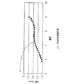
図12および図13は直交化前後における72箇所の弧の各位置での曲率半径を図示するグラフである。図12は、直径3mmの角膜区分に関し、図13は直径7mmの区分に関するものである。各例から分かるように、半経線の弧の曲率半径の変動は直交化により著しく減少している。 12 and 13 are graphs illustrating the radius of curvature at each position of 72 arcs before and after orthogonalization. FIG. 12 relates to a corneal segment having a diameter of 3 mm, and FIG. 13 relates to a segment having a diameter of 7 mm. As can be seen from each example, the variation in the radius of curvature of the semimeridian arc is significantly reduced by orthogonalization.
本発明をコンタクトレンズに対して使用した場合、レンズは、全体を参考として本願中に開示した米国特許第5,880,809号の図7Aおよび図7Bで図示されたレンズ10の構造を有した方が好ましい。コンタクトレンズ10は内部光学部分36、周辺光学部分38、および最外周辺部分34を有することが好ましく、その後部表面は、角膜の対応部分と非対称的および非球面的に一致することが好ましい。この角膜の対応部分は、レンズが着用者の目に掛けられている場合、レンズの最も外側の部分の下にある。本発明によれば、内部光学部分36および周辺光学部分38は別々に直交化する。即ち、内部光学部分は、上述のように直交化し、角膜表面モデルの対応部分を修正する。次に、周辺光学部分38にある半経線に沿って球面の弧を作成することによって同じ工程を行い、角膜モデルの対応部分のどこを修正するのか辿って行く。上述のように、コンタクトレンズにおいては、修正済み角膜モデルはコンタクトレンズの後部を成形するために使用される。米国特許第5,880,809号に記載されているようにコンタクトレンズの前方表面を成形して患者の必要な視力矯正を得る。
When the present invention is used with a contact lens, the lens had the structure of the
本発明から得られる視力改善の一例として、重度の円錐角膜を有する患者の事例を考えることができる。この疾患に普通にあることであるが、患者は眼の中に3つの像、即ち、中央に1つ、周辺に2つの像を見ている。患者が眼鏡をかけると、中央の像はせいぜい20/200に補正できることがあるが、患者は依然として、3つの像を見ている。従来のコンタクトレンズは円錐角膜の眼から落ちるので、患者はそれを使用できない。患者が、米国特許第5,880,809号の図7Aおよび図7Bに示すレンズを着用すると、眼に保持される。中央の像はせいぜい20/40に補正できることがあるが、患者は依然として3つの像を見ている。米国特許第5,880,809号の図7Aおよび図7Bに図示した、別個に直交化した内部光学部分36、および周辺光学部分38を備えたコンタクトレンズを患者が着用すると、患者は1つの像を見ると共に、視力も20/30に補正できる。 As an example of the visual acuity improvement obtained from the present invention, a case of a patient having a severe keratoconus can be considered. As is usual with this disease, the patient sees three images in the eye, one in the center and two in the periphery. If the patient wears glasses, the central image may be corrected to at most 20/200, but the patient still sees three images. The conventional contact lens falls off the keratoconus eye and cannot be used by the patient. When a patient wears the lens shown in FIGS. 7A and 7B of US Pat. No. 5,880,809, it is held in the eye. Although the central image may be corrected to 20/40 at best, the patient still sees three images. When a patient wears a contact lens with separately orthogonal internal optical portion 36 and peripheral optical portion 38, as illustrated in FIGS. 7A and 7B of US Pat. No. 5,880,809, the patient is presented with an image. And the visual acuity can be corrected to 20/30.
図14は、直交化を行った場合と行わない場合との円錐角膜の眼の中央光学部分の半経線弧それぞれの曲率半径を図示したものである。図15は、周辺光学部分の同様の線図である。図15から分かるように、直交化により周辺光学部分全体の曲率半径が大幅に均一化されている。これは明らかに患者が見ていた周辺像を除去している。 FIG. 14 illustrates the radii of curvature of the semi-meridian arcs of the central optical portion of the keratoconic eye with and without orthogonalization. FIG. 15 is a similar diagram of the peripheral optical part. As can be seen from FIG. 15, the radius of curvature of the entire peripheral optical portion is greatly uniformized by orthogonalization. This clearly removes the peripheral image that the patient was seeing.
円錐角膜の眼は、周辺光学部分における直交化の恩恵を著しく受けている。本発明によるコンタクトレンズは2つの光学領域に限定する必要はないと考えられる。即ち、このコンタクトレンズは、中央から次第に遠ざかり、光学領域の全部が別個に直交化される中央光学領域および2つ以上の周辺光学領域を持った後部表面を有することができる。 The keratoconic eye significantly benefits from orthogonalization in the peripheral optics. It is believed that the contact lens according to the present invention need not be limited to two optical regions. That is, the contact lens can have a rear surface with a central optical region and two or more peripheral optical regions that are progressively further away from the center and where all of the optical regions are separately orthogonalized.
重度の状態でない患者に関する限り、直交化済みのコンタクトレンズを使用した場合、全員が好ましい視覚変化に気づいた。視力の通常の補正以上の最も一般的な改善点は、遠近感の増加および色覚の増加が報告されている。また、老視の症候は大幅に低減または除去された。即ち、老視の患者は、異なる距離で焦点が合う部品を有しないコンタクトレンズをかけてもよいが、読書用メガネは必要としない。これは、軽度の屈折障害がある患者に限定するものではない。 As far as patients who are not severe are concerned, everyone noticed favorable visual changes when using orthogonalized contact lenses. The most common improvements over normal correction of vision have been reported as increased perspective and increased color vision. Also, presbyopia symptoms were significantly reduced or eliminated. That is, presbyopic patients may wear contact lenses that do not have components that focus at different distances, but they do not require reading glasses. This is not limited to patients with mild refractive disorders.
図16は、実際の患者の目の角膜が、直径(ローカルZ軸からの距離)を変化させた場合に曲率(半径)がどのように変化するかを図示したものである。この曲線は緩やかな「屈曲部」Kを示し、相対的に急速な曲率の変化を表している。表面モデル分析を用いて、この屈曲部は、その位置は角膜に固有であり、あらゆる眼に存在するが、視力の低下に従って一層顕著になることが分かった。また、屈曲部が発生する(例えば、中央領域が屈曲部の内部で終わる)直径より小さい直径にレンズを直交化した場合、多重の像とゴーストとが起きることも分かった。大抵の眼では、略直径4.5mm内で屈曲点が発生する。従って、大体、この悲惨な障害は、中央領域が略直径4.5mmを越えて伸びることを確実にして避けられる。 FIG. 16 illustrates how the curvature (radius) of the cornea of an actual patient's eye changes when the diameter (distance from the local Z axis) is changed. This curve shows a gentle “bend” K, representing a relatively rapid change in curvature. Using surface model analysis, this bend was found to be more prominent with decreasing visual acuity, although its position is intrinsic to the cornea and is present in every eye. It has also been found that multiple images and ghosts occur when the lens is orthogonalized to a diameter smaller than the diameter at which the bend occurs (for example, the central region ends inside the bend). In most eyes, the bending point occurs within a diameter of approximately 4.5 mm. Thus, for the most part, this catastrophic failure is avoided with certainty that the central region extends beyond approximately 4.5 mm in diameter.
上述の通り、直交化のプロセスは角膜切除処置に適用可能である。処置に先立ち、眼のテスト(上記で引用した特許に記載されているように)で確立している屈折の矯正に提供するために成形された修正済みの角膜表面モデルを作成し、直交化を行う。次に、修正済みの角膜表面モデルと、未修正の角膜表面モデルとを位置合わせし、修正済みの表面が未修正の表面にちょうど接触するまで未修正表面の方へ動かす。最初の接触点が修正済みの表面の中央にあれば、修正済みの表面の周辺部が未修正の表面にちょうど接触するまで、それを修正の表面の方へ動かす。最初の接触点が修正済みの表面の周辺部にあれば、修正済みの表面の中央部が未修正の表面にちょうど接触するまで、それを未修正の表面の方へ動かす。次いで、修正済みの表面が少なくとも部分的に角膜内側にあるようにずらし、ずらした修正済みの表面が角膜の新しい表面になるまで、角膜を切除する。 As described above, the orthogonalization process is applicable to corneal ablation procedures. Prior to treatment, create a modified corneal surface model shaped to provide for the correction of refraction established in the eye test (as described in the patent cited above) and orthogonalize Do. Next, the modified corneal surface model and the unmodified corneal surface model are aligned and moved toward the unmodified surface until the modified surface just contacts the unmodified surface. If the first contact point is in the middle of the modified surface, move it towards the modified surface until the periphery of the modified surface just touches the unmodified surface. If the first contact point is at the periphery of the modified surface, move it toward the unmodified surface until the center of the modified surface just touches the unmodified surface. The modified surface is then displaced so that it is at least partially inside the cornea and the cornea is excised until the displaced modified surface becomes the new surface of the cornea.
この処置は、以前の切除技術の全てに比べて角膜から取り除く物質の量を大幅に減少させると思われる。 This procedure appears to significantly reduce the amount of material removed from the cornea compared to all previous ablation techniques.
本発明の好ましい実施形態を説明用に開示したが、本発明の範囲および精神を逸脱せずに多くの追加、変更、置換が可能なことが当業者に理解される。例えば、本発明は角膜の切除およびコンタクトレンズにのみ適用できるのはなく、白内障レンズ、有水晶体レンズ、眼内レンズ、角膜内レンズ、眼鏡レンズを含む他のいかなる種類のレンズにも適用可能である。 While preferred embodiments of the invention have been disclosed for purposes of illustration, those skilled in the art will recognize that many additions, modifications and substitutions may be made without departing from the scope and spirit of the invention. For example, the invention is not only applicable to corneal ablation and contact lenses, but also to any other type of lens, including cataract lenses, phakic lenses, intraocular lenses, intracorneal lenses, spectacle lenses. .
Claims (35)
a)前記基準軸と前記表面モデルの周辺境界との間にあり、前記表面モデルと前記基準軸を含む平面との交差としての前記表面モデルの特性曲線を生成する
b)閉じて適した実質的に円状の特性弧として、前記特性曲線を評価する
c)前記平面を前記基準軸の回りに回転し、ステップa)及びb)を繰り返して追加の弧を生成し、ステップa),b)及びc)を繰り返して新たな表面モデルを表わす所定数の特性弧を生成する
d)前記新たな表面モデルの特性として、前記平面の角位置に対する弧径を表示する Run computer aided design system, comprising the analysis to simulate the improvement of vision, and approximately Table Wa at least part of the surface of a three-dimensional corneal predetermined reference axis is defined, the corneal image capture It said computer aided design system according to information obtained from the system by using the surface model of the cornea of useful eye, a method of analyzing the cornea of the eye, said computer aided design system to perform the following steps Feature method.
a) generating a characteristic curve of the surface model between the reference axis and a peripheral boundary of the surface model and as an intersection of the surface model and a plane containing the reference axis; b) closed and substantially suitable C) evaluating the characteristic curve as a circular characteristic arc c) rotating the plane about the reference axis and repeating steps a) and b) to generate additional arcs, steps a) and b) And c) are repeated to generate a predetermined number of characteristic arcs representing the new surface model. D) Display the arc diameter for the angular position of the plane as the characteristic of the new surface model.
Applications Claiming Priority (3)
| Application Number | Priority Date | Filing Date | Title |
|---|---|---|---|
| US38560102P | 2002-06-03 | 2002-06-03 | |
| US44902903P | 2003-02-21 | 2003-02-21 | |
| PCT/US2003/017633 WO2003101341A2 (en) | 2002-06-03 | 2003-06-03 | Method and system for improving vision |
Publications (3)
| Publication Number | Publication Date |
|---|---|
| JP2005528165A JP2005528165A (en) | 2005-09-22 |
| JP2005528165A5 JP2005528165A5 (en) | 2006-07-13 |
| JP4654028B2 true JP4654028B2 (en) | 2011-03-16 |
Family
ID=29715374
Family Applications (1)
| Application Number | Title | Priority Date | Filing Date |
|---|---|---|---|
| JP2004508699A Expired - Fee Related JP4654028B2 (en) | 2002-06-03 | 2003-06-03 | Method and system for improving vision |
Country Status (13)
| Country | Link |
|---|---|
| US (1) | US20060189966A1 (en) |
| EP (1) | EP1549238A4 (en) |
| JP (1) | JP4654028B2 (en) |
| KR (1) | KR101093813B1 (en) |
| AU (1) | AU2003243393B2 (en) |
| BR (1) | BR0305058A (en) |
| CA (1) | CA2485508C (en) |
| IL (1) | IL165518A (en) |
| MX (1) | MXPA04012162A (en) |
| NO (1) | NO20040477L (en) |
| NZ (1) | NZ537309A (en) |
| PL (1) | PL373990A1 (en) |
| WO (1) | WO2003101341A2 (en) |
Families Citing this family (23)
| Publication number | Priority date | Publication date | Assignee | Title |
|---|---|---|---|---|
| US8668735B2 (en) | 2000-09-12 | 2014-03-11 | Revision Optics, Inc. | Corneal implant storage and delivery devices |
| US10835371B2 (en) | 2004-04-30 | 2020-11-17 | Rvo 2.0, Inc. | Small diameter corneal inlay methods |
| US8057541B2 (en) | 2006-02-24 | 2011-11-15 | Revision Optics, Inc. | Method of using small diameter intracorneal inlays to treat visual impairment |
| US7776086B2 (en) | 2004-04-30 | 2010-08-17 | Revision Optics, Inc. | Aspherical corneal implant |
| US20070129797A1 (en) * | 2005-12-01 | 2007-06-07 | Revision Optics, Inc. | Intracorneal inlays |
| US10555805B2 (en) | 2006-02-24 | 2020-02-11 | Rvo 2.0, Inc. | Anterior corneal shapes and methods of providing the shapes |
| CN101437462B (en) * | 2006-03-08 | 2015-03-25 | 科学光学股份有限公司 | Method and apparatus for universal improvement of vision |
| US9271828B2 (en) | 2007-03-28 | 2016-03-01 | Revision Optics, Inc. | Corneal implant retaining devices and methods of use |
| US8162953B2 (en) | 2007-03-28 | 2012-04-24 | Revision Optics, Inc. | Insertion system for corneal implants |
| US9549848B2 (en) | 2007-03-28 | 2017-01-24 | Revision Optics, Inc. | Corneal implant inserters and methods of use |
| US7832863B2 (en) * | 2007-12-21 | 2010-11-16 | Ophthonix, Inc. | Customized Z-lens design program |
| EP2259741B1 (en) * | 2008-04-01 | 2017-11-08 | Scientific Optics, Inc. | Universal contact lens posterior surface construction |
| US9539143B2 (en) | 2008-04-04 | 2017-01-10 | Revision Optics, Inc. | Methods of correcting vision |
| JP2011516180A (en) | 2008-04-04 | 2011-05-26 | レヴィジオン・オプティックス・インコーポレーテッド | Corneal inlay design and method for correcting vision |
| US8992013B2 (en) * | 2008-04-30 | 2015-03-31 | Essilor International (Compagnie Generale D'optique) | Method of designing progressive addition lenses |
| US8529060B2 (en) * | 2009-02-19 | 2013-09-10 | Alcon Research, Ltd. | Intraocular lens alignment using corneal center |
| DE102009010467A1 (en) | 2009-02-26 | 2010-09-09 | Carl Zeiss Vision Gmbh | Method and device for determining the position of the ocular pivot point |
| WO2011109571A1 (en) * | 2010-03-03 | 2011-09-09 | Scientific Optics, Inc. | Method and system for improving vision of an eye with macular degeneration |
| US8469948B2 (en) | 2010-08-23 | 2013-06-25 | Revision Optics, Inc. | Methods and devices for forming corneal channels |
| JP5944005B2 (en) | 2011-10-21 | 2016-07-05 | リヴィジョン・オプティックス・インコーポレーテッド | Corneal graft storage and delivery device |
| US10244936B2 (en) * | 2012-07-25 | 2019-04-02 | Johnson & Johnson Vision Care, Inc. | Method and apparatus for engaging and providing vision correction options to patients from a remote location |
| WO2016144404A1 (en) | 2015-03-12 | 2016-09-15 | Revision Optics, Inc. | Methods of correcting vision |
| JP7410656B2 (en) * | 2019-06-25 | 2024-01-10 | ホヤ レンズ タイランド リミテッド | Method for selecting base material lenses for processing eyeglass lenses, and method for manufacturing eyeglass lenses |
Citations (4)
| Publication number | Priority date | Publication date | Assignee | Title |
|---|---|---|---|---|
| JPH09502541A (en) * | 1993-09-09 | 1997-03-11 | サイエンティフィック・オプティクス・インコーポレイテッド | Asymmetric aspheric contact lens |
| WO2000019918A1 (en) * | 1998-10-02 | 2000-04-13 | Scientific Optics, Inc. | Method for diagnosing and improving vision |
| JP2001502810A (en) * | 1996-03-15 | 2001-02-27 | サイエンティフィック オプティクス インク. | contact lens |
| JP2002524770A (en) * | 1998-09-08 | 2002-08-06 | サイエンティフィック オプティクス, インク. | contact lens |
Family Cites Families (7)
| Publication number | Priority date | Publication date | Assignee | Title |
|---|---|---|---|---|
| US5284477A (en) * | 1987-06-25 | 1994-02-08 | International Business Machines Corporation | Device for correcting the shape of an object by laser treatment |
| US6099522A (en) | 1989-02-06 | 2000-08-08 | Visx Inc. | Automated laser workstation for high precision surgical and industrial interventions |
| DE4232915A1 (en) | 1992-10-01 | 1994-04-07 | Hohla Kristian | Device for shaping the cornea by removing tissue |
| US5891131A (en) * | 1993-02-01 | 1999-04-06 | Arizona Board Of Regents | Method and apparatus for automated simulation and design of corneal refractive procedures |
| US5620435A (en) * | 1995-10-05 | 1997-04-15 | Optomedic Medical Technologies, Ltd. | Eye surgery |
| US6149609A (en) * | 1995-10-18 | 2000-11-21 | Scientific Optics, Inc. | Method and apparatus for improving vision |
| AU2001260197A1 (en) * | 2000-04-11 | 2001-10-23 | Thomas Bende | Selective corneal aberrometry |
-
2003
- 2003-06-03 JP JP2004508699A patent/JP4654028B2/en not_active Expired - Fee Related
- 2003-06-03 KR KR1020047019779A patent/KR101093813B1/en not_active IP Right Cessation
- 2003-06-03 WO PCT/US2003/017633 patent/WO2003101341A2/en active Application Filing
- 2003-06-03 CA CA2485508A patent/CA2485508C/en not_active Expired - Fee Related
- 2003-06-03 NZ NZ537309A patent/NZ537309A/en unknown
- 2003-06-03 BR BR0305058-0A patent/BR0305058A/en not_active IP Right Cessation
- 2003-06-03 PL PL03373990A patent/PL373990A1/en not_active Application Discontinuation
- 2003-06-03 MX MXPA04012162A patent/MXPA04012162A/en active IP Right Grant
- 2003-06-03 AU AU2003243393A patent/AU2003243393B2/en not_active Ceased
- 2003-06-03 US US10/516,833 patent/US20060189966A1/en not_active Abandoned
- 2003-06-03 EP EP03756392A patent/EP1549238A4/en not_active Withdrawn
-
2004
- 2004-02-03 NO NO20040477A patent/NO20040477L/en not_active Application Discontinuation
- 2004-12-02 IL IL165518A patent/IL165518A/en not_active IP Right Cessation
Patent Citations (5)
| Publication number | Priority date | Publication date | Assignee | Title |
|---|---|---|---|---|
| JPH09502541A (en) * | 1993-09-09 | 1997-03-11 | サイエンティフィック・オプティクス・インコーポレイテッド | Asymmetric aspheric contact lens |
| JP2001502810A (en) * | 1996-03-15 | 2001-02-27 | サイエンティフィック オプティクス インク. | contact lens |
| JP2002524770A (en) * | 1998-09-08 | 2002-08-06 | サイエンティフィック オプティクス, インク. | contact lens |
| WO2000019918A1 (en) * | 1998-10-02 | 2000-04-13 | Scientific Optics, Inc. | Method for diagnosing and improving vision |
| JP2002526149A (en) * | 1998-10-02 | 2002-08-20 | サイエンティフィック オプティクス, インク. | Diagnosis and improvement of eyesight |
Also Published As
| Publication number | Publication date |
|---|---|
| MXPA04012162A (en) | 2005-04-19 |
| BR0305058A (en) | 2004-11-09 |
| AU2003243393A1 (en) | 2003-12-19 |
| WO2003101341A3 (en) | 2004-03-25 |
| EP1549238A2 (en) | 2005-07-06 |
| NZ537309A (en) | 2007-05-31 |
| CA2485508C (en) | 2012-07-31 |
| NO20040477L (en) | 2004-06-23 |
| JP2005528165A (en) | 2005-09-22 |
| AU2003243393B2 (en) | 2008-04-24 |
| IL165518A0 (en) | 2006-01-15 |
| WO2003101341A2 (en) | 2003-12-11 |
| KR101093813B1 (en) | 2011-12-13 |
| PL373990A1 (en) | 2005-09-19 |
| EP1549238A4 (en) | 2008-03-12 |
| CA2485508A1 (en) | 2003-12-11 |
| KR20050023290A (en) | 2005-03-09 |
| IL165518A (en) | 2012-03-29 |
| US20060189966A1 (en) | 2006-08-24 |
Similar Documents
| Publication | Publication Date | Title |
|---|---|---|
| JP4654028B2 (en) | Method and system for improving vision | |
| JP5313699B2 (en) | Method and apparatus for universal improvement of visual acuity | |
| JP5816078B2 (en) | Rear structure of general-purpose contact lens | |
| AU2014201711B2 (en) | Method and apparatus for universal improvement of vision |
Legal Events
| Date | Code | Title | Description |
|---|---|---|---|
| A521 | Request for written amendment filed |
Free format text: JAPANESE INTERMEDIATE CODE: A523 Effective date: 20060525 |
|
| A621 | Written request for application examination |
Free format text: JAPANESE INTERMEDIATE CODE: A621 Effective date: 20060525 |
|
| A131 | Notification of reasons for refusal |
Free format text: JAPANESE INTERMEDIATE CODE: A131 Effective date: 20090519 |
|
| A521 | Request for written amendment filed |
Free format text: JAPANESE INTERMEDIATE CODE: A523 Effective date: 20090817 |
|
| A131 | Notification of reasons for refusal |
Free format text: JAPANESE INTERMEDIATE CODE: A131 Effective date: 20100223 |
|
| A521 | Request for written amendment filed |
Free format text: JAPANESE INTERMEDIATE CODE: A523 Effective date: 20100519 |
|
| A131 | Notification of reasons for refusal |
Free format text: JAPANESE INTERMEDIATE CODE: A131 Effective date: 20101109 |
|
| A521 | Request for written amendment filed |
Free format text: JAPANESE INTERMEDIATE CODE: A523 Effective date: 20101118 |
|
| TRDD | Decision of grant or rejection written | ||
| A01 | Written decision to grant a patent or to grant a registration (utility model) |
Free format text: JAPANESE INTERMEDIATE CODE: A01 Effective date: 20101214 |
|
| A01 | Written decision to grant a patent or to grant a registration (utility model) |
Free format text: JAPANESE INTERMEDIATE CODE: A01 |
|
| A61 | First payment of annual fees (during grant procedure) |
Free format text: JAPANESE INTERMEDIATE CODE: A61 Effective date: 20101220 |
|
| R150 | Certificate of patent or registration of utility model |
Free format text: JAPANESE INTERMEDIATE CODE: R150 |
|
| FPAY | Renewal fee payment (event date is renewal date of database) |
Free format text: PAYMENT UNTIL: 20131224 Year of fee payment: 3 |
|
| R250 | Receipt of annual fees |
Free format text: JAPANESE INTERMEDIATE CODE: R250 |
|
| R250 | Receipt of annual fees |
Free format text: JAPANESE INTERMEDIATE CODE: R250 |
|
| R250 | Receipt of annual fees |
Free format text: JAPANESE INTERMEDIATE CODE: R250 |
|
| LAPS | Cancellation because of no payment of annual fees |