JP4653917B2 - Method and system for measuring and adjusting the quality of orthogonal transmit diversity signals - Google Patents
Method and system for measuring and adjusting the quality of orthogonal transmit diversity signals Download PDFInfo
- Publication number
- JP4653917B2 JP4653917B2 JP2001520983A JP2001520983A JP4653917B2 JP 4653917 B2 JP4653917 B2 JP 4653917B2 JP 2001520983 A JP2001520983 A JP 2001520983A JP 2001520983 A JP2001520983 A JP 2001520983A JP 4653917 B2 JP4653917 B2 JP 4653917B2
- Authority
- JP
- Japan
- Prior art keywords
- radio frequency
- signal
- frequency diversity
- signals
- diversity
- Prior art date
- Legal status (The legal status is an assumption and is not a legal conclusion. Google has not performed a legal analysis and makes no representation as to the accuracy of the status listed.)
- Expired - Lifetime
Links
Images


Classifications
-
- H—ELECTRICITY
- H04—ELECTRIC COMMUNICATION TECHNIQUE
- H04B—TRANSMISSION
- H04B7/00—Radio transmission systems, i.e. using radiation field
- H04B7/02—Diversity systems; Multi-antenna system, i.e. transmission or reception using multiple antennas
- H04B7/04—Diversity systems; Multi-antenna system, i.e. transmission or reception using multiple antennas using two or more spaced independent antennas
- H04B7/06—Diversity systems; Multi-antenna system, i.e. transmission or reception using multiple antennas using two or more spaced independent antennas at the transmitting station
- H04B7/0697—Diversity systems; Multi-antenna system, i.e. transmission or reception using multiple antennas using two or more spaced independent antennas at the transmitting station using spatial multiplexing
-
- H—ELECTRICITY
- H04—ELECTRIC COMMUNICATION TECHNIQUE
- H04B—TRANSMISSION
- H04B7/00—Radio transmission systems, i.e. using radiation field
- H04B7/02—Diversity systems; Multi-antenna system, i.e. transmission or reception using multiple antennas
- H04B7/04—Diversity systems; Multi-antenna system, i.e. transmission or reception using multiple antennas using two or more spaced independent antennas
- H04B7/06—Diversity systems; Multi-antenna system, i.e. transmission or reception using multiple antennas using two or more spaced independent antennas at the transmitting station
- H04B7/0613—Diversity systems; Multi-antenna system, i.e. transmission or reception using multiple antennas using two or more spaced independent antennas at the transmitting station using simultaneous transmission
- H04B7/0667—Diversity systems; Multi-antenna system, i.e. transmission or reception using multiple antennas using two or more spaced independent antennas at the transmitting station using simultaneous transmission of delayed versions of same signal
- H04B7/0671—Diversity systems; Multi-antenna system, i.e. transmission or reception using multiple antennas using two or more spaced independent antennas at the transmitting station using simultaneous transmission of delayed versions of same signal using different delays between antennas
-
- H—ELECTRICITY
- H04—ELECTRIC COMMUNICATION TECHNIQUE
- H04B—TRANSMISSION
- H04B7/00—Radio transmission systems, i.e. using radiation field
- H04B7/02—Diversity systems; Multi-antenna system, i.e. transmission or reception using multiple antennas
- H04B7/04—Diversity systems; Multi-antenna system, i.e. transmission or reception using multiple antennas using two or more spaced independent antennas
- H04B7/06—Diversity systems; Multi-antenna system, i.e. transmission or reception using multiple antennas using two or more spaced independent antennas at the transmitting station
- H04B7/0613—Diversity systems; Multi-antenna system, i.e. transmission or reception using multiple antennas using two or more spaced independent antennas at the transmitting station using simultaneous transmission
- H04B7/0678—Diversity systems; Multi-antenna system, i.e. transmission or reception using multiple antennas using two or more spaced independent antennas at the transmitting station using simultaneous transmission using different spreading codes between antennas
-
- H—ELECTRICITY
- H04—ELECTRIC COMMUNICATION TECHNIQUE
- H04L—TRANSMISSION OF DIGITAL INFORMATION, e.g. TELEGRAPHIC COMMUNICATION
- H04L1/00—Arrangements for detecting or preventing errors in the information received
- H04L1/02—Arrangements for detecting or preventing errors in the information received by diversity reception
- H04L1/06—Arrangements for detecting or preventing errors in the information received by diversity reception using space diversity
-
- H—ELECTRICITY
- H04—ELECTRIC COMMUNICATION TECHNIQUE
- H04L—TRANSMISSION OF DIGITAL INFORMATION, e.g. TELEGRAPHIC COMMUNICATION
- H04L1/00—Arrangements for detecting or preventing errors in the information received
- H04L1/20—Arrangements for detecting or preventing errors in the information received using signal quality detector
Description
【0001】
発明の分野
本発明は、一般に無線通信に関し、特に無線通信システムにおける直交送信ダイバーシティ信号の品質を測定し調整するための方法とシステムの改善に関する。
【0002】
発明の背景
無線通信システムにおいて、送信器と受信器は、大気インターフェイスすなわちチャネルを介してデータ通信を行う。このような無線チャネルはチャネル損失、多重通路損失、フェージング、他の無線周波数源からの干渉によって悪影響を受けることがある。無線チャネルの効率を改善し、チャネル劣化現象の影響を緩和するために、いわゆる“第三世代セルラ電話システム”等の、拡散スペクトル通信システム用に直交送信ダイバーシティとして知られる伝送方式が提案されている。直交送信ダイバーシティは、スウェーデンのストックホルムにあるETSI(欧州電気通信標準協会)SMG2へのモトローラ社による投稿、表題“直接拡散CDMA用直交送信ダイバーシティ” (1997年9月15〜17日)等の標準機関への様々な投稿において詳細に説明されている。概略を述べると、直交送信ダイバーシティは、2つ以上のアンテナを用いて、互いに直交する拡散符号を用いて拡散したビットストリームを送信する。1つの方式では、データ供給源からのビットは、送信器において2つ以上のダイバーシティ分岐間で切換すなわち分割される。もう1つの方式では、同じデータが、従来の半分のパワーで両方の分岐から送信される。両方の方式において、データは、1つのダイバーシティ分岐において、他のいずれかのダイバーシティ分岐で用いられる拡散符号に直交する拡散符号を用いて拡散される。
【0003】
2つ以上のアンテナを用いてユーザのデータを送信することによって、ダイバーシティが全無線チャネルに付加される。例えば、第1アンテナから送信されたデータがフェージングを受ける場合、第2アンテナから送信されたデータは、同じフェージング状態に陥らないというある統計的な確率がある。従って、加入者装置が正しいデータを受信する確率は大きい。異なるアンテナでの直交拡散は、加入者装置が各信号を独立に受信するように用いられるが、このことは、ダイバーシティ信号が互いに干渉しないことを意味する。これによって、感度すなわち受信器の利得が大きくなり、順方向リンクでのパワーがより小さくなり、またシステムの容量が大きくなる。
【0004】
無線周波数ダイバーシティ信号を生成する上での1つの問題は、2つ以上のダイバーシティアンテナで送信する信号間のタイミングすなわち遅延を制御することである。このことは、無線周波数ダイバーシティ信号間での相体的なタイミングが変化するにつれて信号間での直交性が劣化するため問題になる。換言すれば、これらの無線周波数ダイバーシティ信号が最も直交するのは、同じシステム時間を基準にした直交符号で拡散された時であり、また、この時間基準は、信号がフィルタ処理、アップコンバート処理、また増幅処理される際、他の無線周波数ダイバーシティ信号に対してシフトされない。このような無線周波数ダイバーシティ信号間でのタイミングシフトはまた、送信器や受信器ダイバーシティアンテナ間のケーブル長が等しくない状態で起こり得る。可能性は小さいが、デジタルタイミングのエラーの結果、遅延差が発生する場合がある。
【0005】
直交送信ダイバーシティ送信器のダイバーシティ分岐間の遅延を制御する1つの方法は、遅延を引き起こす可能性のある送信器の部位における構成要素の設計と選択を厳密に制御することである。例えば、フィルタ、アップコンバータ、及び増幅器においては、厳しい仕様範囲内にある厳密に選択した構成要素で設計を実施し得る。この解決策の問題は、そのような厳しい許容範囲で構成要素を仕様指定したり選択したりすることは、極めてコスト高であることである。
【0006】
同様に、送信器とダイバーシティアンテナ間のケーブル長は、信号間の相対遅延が変化しないように同じ長さにしてよい。またここで、送信器とアンテナの据付における精度と品質制御の問題がある。
【0007】
従って、無線通信システムにおいて直交送信ダイバーシティ信号の品質を測定し調整するための方法とシステムの改善に対する必要性が存在することは明らかであり、これによって、無線周波数ダイバーシティ信号間の遅延差の影響を検出し、その遅延の影響を最小限にするために、その遅延を補償するものを送信器に導入する。
【0008】
本発明に特有であると思われる新規特徴は、添付の請求項に記載する。しかしながら、本発明自体並びにその好適な実施形態や他の目的また利点は、次の説明用実施例の詳細な説明を参照し、添付図面と共に読むことによって最もよく理解されるであろう。
【0009】
発明の詳細な説明
次に、図1において、本発明の方法とシステムに基づく直交送信ダイバーシティ送信器と直交送信ダイバーシティ信号の品質を測定し調整するための装置の高水準機能ブロック図を示す。図示したように、送信器20は、データ供給源22を含み、このデータ供給源22は、受信器又は加入者装置に送信されるデータの供給源である。データ供給源22は、好ましくはビットストリームを提供する。このビットストリームは、符号化処理やインターリーブ処理又は他の方法により処理され送信されるが、このビットストリームは、音声、映像、又は受信用加入者装置に送信される他のデータを表す。
【0010】
複数のダイバーシティアンテナから送信ダイバーシティを得るために、データ供給源22が出力するデータストリームから、複数のデータストリームを生成する。直交送信ダイバーシティ送信器の1つの実施形態において、データビットを切換え、データビットを1つおきに又はデータビットの群を1つおきに、送信器20に示す2つのダイバーシティ分岐の一方に出力する。アンテナを3本以上用いる場合は、送信器の全ダイバーシティ分岐間で切換えを実行する。この切換え機能は、切換器24で実行できるが、この切換器24は、1つ以上のビットのダイバーシティ分岐26、28への出力を交互に行う。説明を簡単にするために、2つのダイバーシティ分岐のみを図1に示す。
【0011】
交互直交送信ダイバーシティ送信器において、参照番号30で示す破線を結んで示すように、従来の半分のパワーで送信する場合、ダイバーシティ分岐26、28へのデータストリームは同じデータを含み得る。
【0012】
切換器24が出力するデータストリームは、チャネル拡散符号36、38を用いてデータを拡散するための拡散器32、34に結合される。これらの拡散符号は、図1にウォルシュ符号Wa 、Wb として示すが、これらは、好ましくは互いに直交している。
【0013】
拡散器32、34の出力は、加算器40、42にそれぞれ結合される。加算器40、42は、直交パイロットチャネルをダイバーシティ分岐26、28の信号に加えるために用いられる。これらのパイロットチャネルによって、ダイバーシティ分岐26、28に対応するダイバーシティアンテナから受信された信号を検出、受信、逆拡散するための加入者装置に基準を提供する。好適な実施形態において、パイロットチャネル44、46は、データで変調されない選択された直交ウォルシュ符号である。
【0014】
送信器20が複数のデータチャネルを送信する場合、追加チャネル用の追加拡散データは、拡散データ48から延びる矢印で示すように、加算器40、42で加算し得る。例えば、第2ユーザに属する音声やデータは、データ供給源22やパイロットチャネル44、46からの拡散データと加算し得る。このことによって、各ダイバーシティ分岐に対して1つのパイロットチャネルがある状態で、全ユーザからの直交拡散データの2つの分岐を表す出力を加算器40、42から生成する。
【0015】
本発明の重要な側面によれば、拡散器40、42から出力された信号は、2つのデジタルデータストリーム間の相対遅延を調整する目的のために、遅延回路50、52にそれぞれ結合される。更に詳細に後述するように、送信器やアンテナ系の他の場所で発生する遅延差を補償するために、プロセッサ54からの信号を用いて、遅延回路50、52のいずれか又は両方の時間遅延を設定し得る。好適な実施例において、遅延回路50、52は、既知のデジタル遅延バッファにより実現される。
【0016】
遅延回路50、52からの出力は、無線周波数回路56,58にそれぞれ結合される。これらの回路は、デジタル信号がアンテナ60、62から送信されるように、デジタル信号に対して多数のアナログ処理を実施する。好適な実施例において、アナログ回路56,58は、遅延回路50、52からのデジタル信号のフィルタ処理、アップコンバート処理、及び増幅処理を行う。これらの回路はアナログであるために、これらの回路によってもたらされる遅延は、製造時膨大なコストをかけない限り制御不可能である。従って、アナログ回路56,58の出力は、出力が搬送するデジタル情報に対しては、時間的に一致していない可能性がある。時間整合の差異すなわち遅延差によって、分岐26、28における無線周波数ダイバーシティ信号間の直交性の度合いが減少する。直交性が減少すると、受信器での干渉が大きくなるために無線周波数チャネルも効率的ではなくなり、通常これによってデータ伝送にエラーが生ずる。補償する場合、通常、順方向リンクパワーを大きくし、これによってシステム容量が低下する。
【0017】
無線周波数アナログ回路56,58の出力は、ケーブルや他の伝送手段64,66を介して、アンテナ60、62へ送信されるが、ここでは、送信ダイバーシティ信号を提供するために、アンテナは両者間で間隔を空けて取り付けられている。ケーブル64,66間の長さの差は、アンテナ60、62から送信される第1及び第2無線周波数ダイバーシティ信号間において遅延差をもたらすもう1つの原因である。ケーブルにおける異なる遅延は、ケーブルの物理的な又は電気的な長さの差によって発生し得る。
【0018】
また図1に、信号品質測定器70を示すが、これには、無線周波数結合器74、76からの信号を加算するための加算器72が含まれる。結合器74、76は、ケーブル64,66からの少量のエネルギを消費するいくつかの既に知られた結合器のいずれか1つで実現される。本発明の目的のために、結合器74、76は、幾つかの場所に配置することに留意されたい。例えば、結合器74、76は、送信器20を収納する筐体内に配置し得る。これら結合器はまたケーブル64,66内に配置し得る。更に、結合器74、76は、アンテナ60、62への電源供給ポイント付近に配置し得る。この位置において、結合器74、76は、ケーブル64,66の長さの差によってもたらされ得るあらゆる遅延を含み、アンテナ60、62から送信される信号間の実際の遅延時間を表す信号を生成し得る。
【0019】
結合器74、76に接続された加算器72は、それぞれダイバーシティ分岐26、28における第1及び第2無線周波数ダイバーシティ信号の和を表す無線周波数サンプル信号を生成する。この無線周波数サンプル信号は、スイッチ78に結合されるが、このスイッチ78は、アンテナ80等のアンテナからの1つおきの信号を選択するために用い得る光学スイッチである。アンテナ80は、伝搬経路82,84を介して信号受信し、また、本来、アンテナ60、62から送信される信号を加算することに留意されたい。好適な実施例において、経路82,84を介した遅延が等しくなるように、アンテナ80は、アンテナ60、62から等距離の位置に配置する。信号品質測定器70は、スイッチ78を含む必要はなく、信号品質測定器70は、アンテナ80又は加算器72で無線周波数サンプル信号を生成でき、又は、ある実施例は、両方を含み、スイッチ78を用いて無線周波数サンプル信号を選択する場合があることに留意されたい。
【0020】
第1及び第2無線周波数ダイバーシティ信号の和を表す無線周波数サンプル信号は、無線周波数ダウンコンバータ86へ入力され、ここで、信号は、ダウンコンバート処理、フィルタ処理、及びサンプリング処理され、デジタルデータストリームが生成される。無線周波数ダウンコンバータ86の出力はデジタルベースバンド信号であり、この信号は、受信信号を音声やユーザデータに変換するために加入者装置で行われる処理等の後続の処理に適している。
【0021】
無線周波数ダウンコンバータ86から出力されるデジタルベースバンド信号は、チップタイミング再生回路88とチャネル符号逆拡散器90へ入力される。好ましくは、チップタイミング再生回路88には、送信器20の選択された1つのダイバーシティ分岐26、28において、無線周波数ダイバーシティ信号の生成に用いる時間基準に対応した時間基準を求め生成する検索器及び相関器が含まれる。チップタイミング再生回路88は、様々な時間オフセットを有する局部的に生成されたチャネル拡散シーケンスと、無線周波数ダウンコンバータ86が出力するベースバンド信号において予想されるP0等のチャネル拡散シーケンスとの相関を最大にしようとする。このことは、加入者装置がパイロットチャネルを求める際発生する処理と同様である。
【0022】
無線周波数ダウンコンバータ86の出力への結合の他に、チャネル符号逆拡散器90もまた、チップタイミング再生回路88が出力する時間基準に結合される。チャネル符号逆拡散器90には、1つ以上のチャネル逆拡散符号発生器、すなわち複数のウォルシュ符号発生器が含まれ、これは各々、チップタイミング再生回路88が出力する時間基準をいずれ参照する。これらのチャネル逆拡散符号発生器は、P0、P1及びウォルシュ符号発生器Wa 〜Wnとして図示する。
【0023】
チャネル符号逆拡散器90内において、無線周波数ダウンコンバータ86のベースバンドデジタル出力は、図示したように、1つ以上の逆拡散処理を行うために1つ以上の逓倍器でチャネル拡散符号によって逓倍される。従って、逓倍器すなわち逆拡散器92は、送信器20の拡散器32、34によって適用されたチャネル符号拡散を除去する。
【0024】
各逆拡散器92の出力は、チャネルエネルギ検出器94へ入力される。チャネルエネルギ検出器94の機能は、各符号化チャネルの逆拡散出力のエネルギを検出することである。エネルギを検出するために、各出力は、整数倍の拡散符号周期に渡って積分される。
【0025】
選択された符号化チャネルのエネルギを検出した後、そのエネルギを表す信号がプロセッサ54に入力される。本発明の重要な側面によれば、プロセッサ54は、様々なチャネルのエネルギを確認し、未使用のチャネルにおいてエネルギを検出した際は、送信器20における第1及び第2無線周波数ダイバーシティ信号の遅延差に比例した出力を生成する。プロセッサ54は、適当なソフトウェアを実行するプログラマブルプロセッサで実現される。一方、状態機械すなわち専用の集積回路を用いてもよい。プロセッサ54を用いて、無線周波数ダウンコンバータ86が出力した信号の成分の測定特性を示すデータを処理してもよい。プロセッサ54は、データの拡大縮小、あるいはデータの表示用又は遅延回路50、52の制御用の信号にフォーマット化し得る。プロセッサ54の動作は、以下において更に詳細に説明する。
【0026】
プロセッサ54の出力は、その出力が送信器20の遅延差を手作業で調整するための基準として用いられるように、ディスプレイ96に表示し得る。また、プロセッサ54が出力する信号を用いて、送信器20の動作中、自動的に遅延回路50、52を調整し得る。
【0027】
そのような自動調整を実施する場合、プロセッサ54は、未使用チャネルのチャネルエネルギを最小限にする遅延回路50、52の遅延の組み合わせを選択するようにプログラミングし得る。すなわち、チャネル符号逆拡散器90は、チップタイミング再生回路88が生成する時間基準を用い、ダイバーシティ分岐26又はダイバーシティ分岐28のいずれかにおいて生成された信号の一部ではなかったウォルシュ符号で表されるチャネルを復号又は逆拡散し得る。
【0028】
チップタイミング再生回路88が再生した時間基準がダイバーシティ分岐26からのものである場合、チャネル符号逆拡散器90とチャネルエネルギ検出器94は、未使用ウォルシュ符号上の信号エネルギ等のダイバーシティ分岐28が生成した信号の信号特性を測定し、送信器20において第1及び第2無線周波数ダイバーシティ信号間の遅延差を示すプロセッサ54から信号を生成することに留意されたい。従って、一方のダイバーシティ分岐26の時間基準は、他方のダイバーシティ分岐28で生成された信号の特性を測定し、2つのダイバーシティ分岐で生成された第1及び第2無線ダイバーシティ信号間に遅延差があるかどうかを示すために用いられる。
【0029】
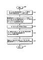
次に、図2において、本発明の方法とシステムに基づく直交送信ダイバーシティ信号の品質を測定し調整するプロセスを示す高水準論理フローチャートを図示する。図示したように、このプロセスは、ブロック200で始まり、その後、ブロック202に進み、ここで、ダイバーシティ送信器において第1及び第2無線周波数ダイバーシティ信号の和を表す無線周波数サンプル信号を生成する。本発明の1つの実施例において、第1及び第2無線周波数ダイバーシティ信号は、ダイバーシティ送信器において、パワー増幅器の出力から少量の一部のエネルギを消費する結合器でサンプリングしてもよい。これらの結合器は、送信器の筐体内に配置したり、あるいは、送信器とダイバーシティアンテナ間のアンテナケーブル中に配置したり、又は送信ダイバーシティアンテナの基部付近に配置し得る。結合器が送信ダイバーシティアンテナの基部付近に配置された場合、本発明が直交送信ダイバーシティ信号の品質を測定する時、伝送線の長さの差が考慮される。
【0030】
和を生成するために、加算器を用いて、結合器が生成する信号を加算する。好ましくは、遅延差が信号品質測定器70に生じないように、各結合器と加算器間のケーブル長は同じにすべきである。
【0031】
他の実施例において、ブロック202で表されるステップは、ダイバーシティアンテナ60、62が送信する信号を、図1のアンテナ80等のサンプル受信アンテナで受信することによって実現し得る。このアンテナは、本来、第1及び第2無線周波数ダイバーシティ信号を加算する段階を含むことに留意されたい。また、両方のダイバーシティアンテナからの伝搬時間が同じになるように、アンテナ80は、アンテナ60、62から等距離に配置すべきであることに留意されたい。アンテナ60、62間の途中にアンテナ80を配置することは、確実に伝搬遅延を両方のダイバーシティアンテナから同一にするための良い方法である。
【0032】
次に、ブロック204に示すように、無線周波数サンプル信号のダウンコンバート処理を行い、それぞれ第1及び第2無線周波数ダイバーシティ信号に対応する第1及び第2の成分を有するダウンコンバート信号をダイバーシティ送信器内に生成する。このステップは、無線周波数サンプル信号のフィルタ処理、ダウンコンバート処理、及びサンプリングを行う信号無線周波数ダウンコンバータを用いて、デジタルデータストリームを生成することによって実行し得る。単一ダウンコンバータを用いることによって、ダウンコンバートプロセスによって付加された遅延は、第1及び第2無線周波数ダイバーシティ信号に対していずれも同一になる。品質測定プロセスで付加された遅延が第1及び第2無線周波数ダイバーシティ信号に対して同一である限り、送信器における第1及び第2ダイバーシティ信号間の遅延差は、充分正確に測定可能である。
【0033】
ダウンコンバート処理ステップの後、第1無線周波数ダイバーシティ信号に対応する第1成分から、ブロック206に図示するように、第1時間基準を再生する。このステップは、上記において、図1を参照して検討したように、チップタイミング再生回路88で実行し得る。好適な実施例において、第1時間基準は、例えば、送信器20の分岐26等の第1ダイバーシティ分岐からのパイロット信号を検索することによって再生される。
【0034】
次に、第1成分からの時間基準を用いて、第2成分の特性を測定する。ここで、この特性は、ブロック208に図示したように、第1及び第2無線周波数ダイバーシティ信号間の遅延差を示す。本発明の1つの実施例において、第2無線周波数ダイバーシティ信号を生成する際、未割当ての、すなわち未使用のウォルシュチャネルのエネルギを測定する。ここで、このエネルギは、第1無線周波数ダイバーシティ信号から再生された第1時間基準を用いて測定される。
【0035】
例えば、図1において、第1無線周波数ダイバーシティ信号からのタイミングは、送信器20のダイバーシティ分岐26からのパイロットチャネルP044を検索し受信するチップタイミング再生回路88によって再生し得る。このタイミングを用いて、チャネル逆拡散符号、例えば、Wdを生成する。このチャネル逆拡散符号は、ダイバーシティ分岐28上のトラフィック搬送には割当てられない。チャネル符号逆拡散器90は、未割当てチャネルにおけるエネルギを捜しているため、チャネルエネルギ検出器94は、アンテナ60、62から送信された第1及び第2無線周波数ダイバーシティ信号間の遅延がほぼ同じか、あるいはチップ時間に対して小さければ、未使用ウォルシュチャネル上に有意なエネルギを見つけることは全く予想されない。逆に、第1及び第2無線周波数ダイバーシティ信号間に遅延差があれば、ダイバーシティ分岐26、28間での直交性の度合いが小さいため、割当てされていないウォルシュチャネル上にエネルギが現れる。従って、未割当てウォルシュチャネル上のエネルギの存在は、送信器20における第1及び第2無線周波数ダイバーシティ信号間の遅延差を示す第2成分の特性であると考えられる。
【0036】
本発明の他の実施例において、チップタイミング再生回路88と同様の回路が、チップタイミング再生回路88と並列に動作して、第2無線周波数ダイバーシティ信号の時間基準を再生してもよい。換言すれば、チップタイミング再生回路88は、P044からのチップタイミングを再生する一方で、もう1つの同様な回路がP146のチップタイミングを再生してもよい。このステップは図3に示す回路で実行してもよく、これについては、以下において更に詳細に検討する。
【0037】
遅延を示す特性が一旦測定されると、ブロック210に図示したように、送信器における第1及び第2無線周波数ダイバーシティ信号間の遅延差が減少又は無くなるように変更される。相対的な遅延が減少すると、チャネルの効率や直交送信ダイバーシティ送信器20の性能効率が良くなる。
【0038】
ブロック210に示すステップは、図1の遅延回路50、52によって実行される第1対の遅延値を選択することによって実施し得る。次に、遅延差を示す特性を測定し、また測定された基準を記憶してよい。測定後、異なる対の遅延値を、遅延回路50、52に読み込み、第2の測定を実施し、遅延差を示す第2の基準を得る。次に、この2つの基準を比較し、遅延設定値の変化が良い変化であったかどうかを判断する。この変化が、遅延差の兆候を減少させるような良い変化であった場合、プロセッサ54は、第1及び第2無線周波数ダイバーシティ信号間の相対遅延を更に減少させるのと同じように、相対的な遅延を大きくする。
【0039】
この変化が直交送信ダイバーシティ信号の品質を改善しなかった場合、プロセッサ54は、遅延の変化の方向を逆転し、第1及び第2無線周波数ダイバーシティ信号間の遅延差が最小限になるように、もう1つの対の遅延値を生成し、遅延回路50、52がその遅延を他方の方向へ変更する。図3に示す実施例において、ブロック210に図示したステップは、ダイバーシティ分岐26、28用の時間基準間における時間比較の出力を確認するプロセッサ54において実施してもよい。
【0040】
ダイバーシティ分岐26、28にもたらされる遅延差の影響を最小限にするために、第1及び第2無線周波数ダイバーシティ信号間の相対的な遅延を変更した後、ブロック212に示すようにプロセスは終了する。
【0041】
次に、図3において、本発明の他の実施例を示すが、これは、直交送信ダイバーシティ送信器と直交送信ダイバーシティ信号の品質を測定するための装置の高水準機能ブロック図に示したものである。図示したように、無線周波数ダウンコンバータ86からのベースバンドデジタル出力は、2つのチップタイミング再生回路88、100に入力される。図示したように、チップタイミング再生回路88は、パイロットチャネルP044と相関を取ることによって、送信器20におけるダイバーシティ分岐26からの時間基準を再生する。同様に、チップタイミング再生回路100は、パイロットチャネルP146と相関を取ることによって、ダイバーシティ分岐28からの時間基準を再生する。
【0042】
チップタイミング再生回路88及びチップタイミング再生回路100によって出力された時間基準は、両方共、比較器102に入力される。この比較器102は、この2つの時間基準を比較し、その時間基準に比例する信号を出力する。この信号は、プロセッサ54に入力され、この後、プロセッサ54によって、この信号は、遅延回路50、52を制御するための然るべき遅延値に変換される。
【0043】
当業者には明らかであろうが、本発明を用いて、直交送信ダイバーシティ送信器の異なるダイバーシティ分岐において生成される信号が受ける遅延差を検出し補償することができる。直交送信ダイバーシティ方式から最大の利点を実現するために、ダイバーシティ分岐間の遅延を補償する必要がある。
【0044】
本発明の1つの実施例において、直交送信ダイバーシティ送信器において第1及び第2無線周波数ダイバーシティ信号間の遅延差を示す特性として直交性が測定される。他の実施例においては、各ダイバーシティ分岐からの時間基準が、送信器のダイバーシティ分岐における相対的な遅延を変更するために、再生され比較される。また本発明には、信号品質測定器のアナログ部分における遅延により、第1及び第2無線周波数ダイバーシティ信号間の遅延差の変更を回避するという利点がある。信号品質測定器において付加された遅延は、いずれも第1及び第2送信ダイバーシティ信号の両方に等しく加算される。
【0045】
本発明の好適な実施例に関する上述の説明は、図示及び説明の目的のためになされたものである。網羅的又は開示された通りの形態に本発明を制限することを意図するものではない。上述の教示に鑑みて、明らかな修正や変更や可能である。実施例は、本発明の原理及びその応用例を最も良く示すために、また、いずれの当業者でも本発明を様々な実施例において用い得るように、また試みようとする特定の用途に適合するように様々な変更を行い得るように、選択し、また説明した。これら全ての修正や変更は、請求項が公正に、合法的に、また正当に権利化される範囲に基づき解釈された時、添付の請求項によって定められる本発明の範囲内にあるものである。
【図面の簡単な説明】
【図1】 本発明の方法とシステムに基づく直交送信ダイバーシティ送信器と直交送信ダイバーシティ信号の品質を測定するための装置の高水準機能ブロック図。
【図2】 本発明の方法とシステムに基づく直交送信ダイバーシティ信号の品質を測定し調整するプロセスの高水準論理フローチャート。
【図3】 直交送信ダイバーシティ送信器と直交送信ダイバーシティ信号の品質を測定するための装置の高水準機能ブロック図。[0001]
Field of Invention
The present invention relates generally to wireless communications, and more particularly to improvements in methods and systems for measuring and adjusting the quality of orthogonal transmit diversity signals in wireless communication systems.
[0002]
Background of the Invention
In wireless communication systems, transmitters and receivers communicate data via an atmospheric interface or channel. Such radio channels may be adversely affected by channel loss, multipath loss, fading, and interference from other radio frequency sources. In order to improve the efficiency of radio channels and mitigate the effects of channel degradation phenomena, transmission schemes known as orthogonal transmission diversity have been proposed for spread spectrum communication systems, such as so-called “third generation cellular telephone systems” . Orthogonal Transmit Diversity is a standard organization such as a contribution by Motorola to ETSI (European Telecommunications Standards Institute) SMG2 in Stockholm, Sweden, titled "Orthogonal Transmit Diversity for Direct Spread CDMA" (September 15-17, 1997) It is explained in detail in various posts to. In brief, orthogonal transmission diversity uses two or more antennas to transmit a spread bitstream using spreading codes that are orthogonal to each other. In one scheme, bits from the data source are switched or split between two or more diversity branches at the transmitter. In another scheme, the same data is transmitted from both branches at half the conventional power. In both schemes, data is spread in one diversity branch using a spreading code that is orthogonal to the spreading code used in any other diversity branch.
[0003]
Diversity is added to all radio channels by transmitting user data using two or more antennas. For example, if data transmitted from the first antenna is subject to fading, there is some statistical probability that the data transmitted from the second antenna will not fall into the same fading state. Therefore, the probability that the subscriber device receives correct data is high. Orthogonal spreading with different antennas is used so that the subscriber unit receives each signal independently, which means that the diversity signals do not interfere with each other. This increases sensitivity or receiver gain, reduces power on the forward link, and increases system capacity.
[0004]
One problem in generating radio frequency diversity signals is controlling the timing or delay between signals transmitted by two or more diversity antennas. This is a problem because the orthogonality between signals deteriorates as the relative timing between radio frequency diversity signals changes. In other words, these radio frequency diversity signals are most orthogonal when they are spread with orthogonal codes relative to the same system time, and this time reference is used to filter, upconvert, Also, when amplified, it is not shifted with respect to other radio frequency diversity signals. Such timing shifts between radio frequency diversity signals can also occur with unequal cable lengths between transmitter and receiver diversity antennas. Although the possibility is small, a delay difference may occur as a result of a digital timing error.
[0005]
One way to control the delay between diversity branches of an orthogonal transmit diversity transmitter is to tightly control the design and selection of components at the transmitter site that can cause the delay. For example, filters, upconverters, and amplifiers may be designed with strictly selected components that are within tight specifications. The problem with this solution is that it is very expensive to specify and select components with such tight tolerances.
[0006]
Similarly, the cable length between the transmitter and the diversity antenna may be the same length so that the relative delay between the signals does not change. Also here are the problems of accuracy and quality control in the installation of the transmitter and antenna.
[0007]
Thus, it is clear that there is a need for improved methods and systems for measuring and adjusting the quality of orthogonal transmit diversity signals in wireless communication systems, thereby reducing the effects of delay differences between radio frequency diversity signals. In order to detect and minimize the effects of that delay, something that compensates for that delay is introduced into the transmitter.
[0008]
The novel features believed to be characteristic of the invention are set forth in the appended claims. However, the invention itself, as well as preferred embodiments and other objects and advantages thereof, will be best understood by referring to the following detailed description of the illustrative examples and when read in conjunction with the accompanying drawings.
[0009]
Detailed Description of the Invention
Referring now to FIG. 1, a high level functional block diagram of an apparatus for measuring and adjusting the quality of an orthogonal transmit diversity transmitter and an orthogonal transmit diversity signal based on the method and system of the present invention is shown. As shown, the
[0010]
In order to obtain transmission diversity from a plurality of diversity antennas, a plurality of data streams are generated from the data stream output from the
[0011]
In an alternating orthogonal transmit diversity transmitter, the data stream to
[0012]
The data stream output by the
[0013]
The outputs of
[0014]
When the
[0015]
According to an important aspect of the present invention, the signals output from the
[0016]
Outputs from
[0017]
The outputs of the radio
[0018]
Also shown in FIG. 1 is a signal
[0019]
An
[0020]
A radio frequency sample signal representing the sum of the first and second radio frequency diversity signals is input to a
[0021]
The digital baseband signal output from the radio frequency down
[0022]
In addition to coupling to the output of
[0023]
Within the
[0024]
The output of each
[0025]
After detecting the energy of the selected encoded channel, a signal representative of that energy is input to the
[0026]
The output of the
[0027]
When performing such automatic adjustment, the
[0028]
When the time reference recovered by chip timing
[0029]
Referring now to FIG. 2, a high level logic flowchart illustrating a process for measuring and adjusting the quality of an orthogonal transmit diversity signal based on the method and system of the present invention is illustrated. As shown, the process begins at
[0030]
To generate the sum, an adder is used to add the signals generated by the combiner. Preferably, the cable length between each combiner and adder should be the same so that no delay difference occurs in the
[0031]
In other embodiments, the step represented by block 202 may be accomplished by receiving a signal transmitted by
[0032]
Next, as shown in block 204, the radio frequency sample signal is down-converted, and the down-convert signal having first and second components corresponding to the first and second radio frequency diversity signals, respectively, is transmitted to the diversity transmitter. Generate within. This step may be performed by generating a digital data stream using a signal radio frequency downconverter that filters, downconverts, and samples the radio frequency sample signal. By using a single downconverter, the delay added by the downconversion process is the same for both the first and second radio frequency diversity signals. As long as the delay added in the quality measurement process is the same for the first and second radio frequency diversity signals, the delay difference between the first and second diversity signals at the transmitter can be measured sufficiently accurately.
[0033]
After the down-conversion processing step, the first time reference is regenerated as illustrated in
[0034]
Next, the characteristics of the second component are measured using the time reference from the first component. Here, this characteristic indicates the delay difference between the first and second radio frequency diversity signals, as illustrated in
[0035]
For example, in FIG. 1, the timing from the first radio frequency diversity signal is the pilot channel P from the
[0036]
In other embodiments of the present invention, a circuit similar to the chip
[0037]
Once the characteristic indicative of delay is measured, as illustrated in
[0038]
The step shown in
[0039]
If this change did not improve the quality of the orthogonal transmit diversity signal, the
[0040]
After changing the relative delay between the first and second radio frequency diversity signals to minimize the effect of the differential delay introduced to
[0041]
Next, another embodiment of the present invention is shown in FIG. 3, which is shown in a high level functional block diagram of an apparatus for measuring the quality of an orthogonal transmit diversity transmitter and an orthogonal transmit diversity signal. is there. As shown, the baseband digital output from the radio frequency down
[0042]
Both time references output by the chip
[0043]
As will be apparent to those skilled in the art, the present invention can be used to detect and compensate for delay differences experienced by signals generated at different diversity branches of an orthogonal transmit diversity transmitter. In order to achieve the maximum benefit from the orthogonal transmit diversity scheme, it is necessary to compensate for the delay between the diversity branches.
[0044]
In one embodiment of the present invention, orthogonality is measured at the orthogonal transmit diversity transmitter as a characteristic indicative of the delay difference between the first and second radio frequency diversity signals. In another embodiment, the time reference from each diversity branch is regenerated and compared to change the relative delay in the transmitter diversity branch. The present invention also has the advantage of avoiding changing the delay difference between the first and second radio frequency diversity signals due to the delay in the analog portion of the signal quality meter. Any delay added in the signal quality meter is added equally to both the first and second transmit diversity signals.
[0045]
The foregoing description of the preferred embodiment of the present invention has been presented for purposes of illustration and description. It is not intended to be exhaustive or to limit the invention to the precise form disclosed. Obviously, modifications and variations are possible in light of the above teachings. The examples are intended to best illustrate the principles of the invention and its applications, and to enable any person skilled in the art to use the invention in various embodiments and to suit the particular application to be attempted. As such, various changes can be made and explained. All these modifications and changes are within the scope of the present invention as defined by the appended claims when the claims are construed fairly, legally and legitimately. .
[Brief description of the drawings]
FIG. 1 is a high-level functional block diagram of an apparatus for measuring the quality of an orthogonal transmit diversity transmitter and an orthogonal transmit diversity signal based on the method and system of the present invention.
FIG. 2 is a high level logic flowchart of a process for measuring and adjusting the quality of an orthogonal transmit diversity signal based on the method and system of the present invention.
FIG. 3 is a high level functional block diagram of an apparatus for measuring the quality of an orthogonal transmit diversity transmitter and an orthogonal transmit diversity signal.
Claims (10)
前記第1及び第2無線周波数ダイバーシティ信号の和を表す無線周波数サンプル信号を生成する段階と、
前記無線周波数サンプル信号をダウンコンバート処理して、それぞれ前記第1及び第2無線周波数ダイバーシティ信号に対応する第1及び第2成分を有するダウンコンバート信号を生成する段階と、
前記第1成分から、前記第1無線周波数ダイバーシティ信号の第1時間基準を再生する段階と、
前記第1時間基準を用いて、前記第1及び第2無線周波数ダイバーシティ信号間の遅延差を示す前記第2成分の特性を測定する段階と、
を含み、
前記第1及び第2無線周波数ダイバーシティ信号の和を表す無線周波数サンプル信号を生成する段階は、さらに、
前記第1無線周波数ダイバーシティ信号と対となる第1サンプル信号を生成すること、
前記第2無線周波数ダイバーシティ信号と対となる第2サンプル信号を生成すること、
前記第1サンプル信号と第2サンプル信号とを加算して、前記第1及び第2無線周波数ダイバーシティ信号の和を表す無線周波数サンプル信号を生成すること
を含むことを特徴とする方法。A method for measuring the quality of an orthogonal transmit diversity signal in a wireless communication system generated by a transmitter having first and second radio frequency diversity signals for transmission from first and second transmit diversity antennas. ,
Generating a radio frequency sample signal representative of a sum of the first and second radio frequency diversity signals;
The radio frequency sample signal by down-converting processes, and stage that generates a downconversion bets signals, each having a first and a second component corresponding to the first and second radio frequency diversity signals,
Regenerating a first time reference of the first radio frequency diversity signal from the first component;
Measuring the second component characteristic indicative of a delay difference between the first and second radio frequency diversity signals using the first time reference;
Only including,
Generating a radio frequency sample signal representative of a sum of the first and second radio frequency diversity signals;
Generating a first sample signal paired with the first radio frequency diversity signal;
Generating a second sample signal paired with the second radio frequency diversity signal;
Adding the first sample signal and the second sample signal to generate a radio frequency sample signal representing a sum of the first and second radio frequency diversity signals;
Wherein the free Mukoto a.
前記第2成分から、前記第2無線周波数ダイバーシティ信号の第2時間基準を再生する段階と、
第1と第2時間基準の時間の比較を行う段階と、を含むことを特徴とする方法。The method for measuring the quality of an orthogonal transmit diversity signal according to claim 1, wherein the step of measuring a characteristic of the second component indicative of a delay difference between the first and second radio frequency diversity signals comprises: Furthermore,
Regenerating a second time reference of the second radio frequency diversity signal from the second component;
Comparing the first and second time reference times.
アンテナで、前記第1及び第2送信ダイバーシティアンテナから送信される信号を受信し、前記第1及び第2無線周波数ダイバーシティ信号の和を表す無線周波数サンプル信号を生成する段階を含むことを特徴とする方法。The method for measuring the quality of an orthogonal transmit diversity signal according to claim 1, wherein the step of generating a radio frequency sample signal representative of the sum of the first and second radio frequency diversity signals further comprises:
Receiving a signal transmitted from the first and second transmit diversity antennas and generating a radio frequency sample signal representing a sum of the first and second radio frequency diversity signals at an antenna; Method.
の方法であって、更に、前記第1及び第2無線周波数ダイバーシティ信号間の遅延差を示す前記第2成分の測定された特性に応じて、前記第1及び第2無線周波数ダイバーシティ信号間の相対的な遅延を変更する段階を含むことを特徴とする方法。The method for measuring the quality of an orthogonal transmit diversity signal according to claim 1, further comprising a measured characteristic of the second component indicative of a delay difference between the first and second radio frequency diversity signals. In response, the method includes changing a relative delay between the first and second radio frequency diversity signals.
前記第1及び第2無線周波数ダイバーシティ信号の和を表す無線周波数サンプル信号を生成するための手段と、
前記無線周波数サンプル信号をダウンコンバート処理して、それぞれ前記第1及び第2無線周波数ダイバーシティ信号に対応する第1及び第2成分を有するダウンコンバート信号を生成する手段と、
前記第1成分から、前記第1無線周波数ダイバーシティ信号の第1時間基準を再生する手段と、
前記第1時間基準を用いて、前記第1及び第2無線周波数ダイバーシティ信号間の遅延差を示す前記第2成分の特性を測定する手段と、
を備え、前記第1及び第2無線周波数ダイバーシティ信号の和を表す無線周波数サンプル信号を生成するための手段は、さらに、
前記第1無線周波数ダイバーシティ信号と対となる第1サンプル信号を生成する手段と、
前記第2無線周波数ダイバーシティ信号と対となる第2サンプル信号を生成する手段と、
前記第1サンプル信号と第2サンプル信号とを加算して、前記第1及び第2無線周波数ダイバーシティ信号の和を表す無線周波数サンプル信号を生成する手段と
を含むことを特徴とするシステム。A system for measuring the quality of an orthogonal transmit diversity signal in a wireless communication system generated by a transmitter having first and second radio frequency diversity signals for transmission from first and second diversity antennas, comprising:
Means for generating a radio frequency sample signal representative of a sum of the first and second radio frequency diversity signals;
The radio frequency sample signal by down-converting processing, and hand stage that generates a downconversion bets signals, each having a first and a second component corresponding to the first and second radio frequency diversity signals,
Means for regenerating a first time reference of the first radio frequency diversity signal from the first component;
Means for measuring a characteristic of the second component indicative of a delay difference between the first and second radio frequency diversity signals using the first time reference;
And means for generating a radio frequency sample signal representative of the sum of the first and second radio frequency diversity signals further comprises:
Means for generating a first sample signal paired with the first radio frequency diversity signal;
Means for generating a second sample signal paired with the second radio frequency diversity signal;
Means for adding the first sample signal and the second sample signal to generate a radio frequency sample signal representing a sum of the first and second radio frequency diversity signals;
System characterized in including Mukoto a.
前記第2成分から、前記第2無線周波数ダイバーシティ信号の第2時間基準を再生する手段と、
第1と第2時間基準の時間の比較を行う手段と、を含むことを特徴とするシステム。7. A system for measuring the quality of an orthogonal transmit diversity signal according to claim 6, wherein said means for measuring a characteristic of said second component indicative of a delay difference between said first and second radio frequency diversity signals. Furthermore,
Means for regenerating a second time reference of the second radio frequency diversity signal from the second component;
Means for comparing the time of the first and second time reference.
前記第1及び第2送信ダイバーシティアンテナから送信される信号を受信し、前記第1及び第2無線周波数ダイバーシティ信号の和を表す無線周波数サンプル信号を生成するアンテナを含むことを特徴とするシステム。The system for measuring the quality of an orthogonal transmit diversity signal according to claim 6, wherein said means for generating a radio frequency sample signal representative of the sum of said first and second radio frequency diversity signals further comprises:
A system comprising: an antenna that receives signals transmitted from the first and second transmit diversity antennas and generates a radio frequency sample signal that represents a sum of the first and second radio frequency diversity signals.
Applications Claiming Priority (3)
| Application Number | Priority Date | Filing Date | Title |
|---|---|---|---|
| US09/387,107 US6327299B1 (en) | 1999-08-31 | 1999-08-31 | Method and system for measuring and adjusting the quality of an orthogonal transmit diversity signal in a wireless communications system |
| US09/387,107 | 1999-08-31 | ||
| PCT/US2000/022862 WO2001017156A1 (en) | 1999-08-31 | 2000-08-19 | Method and system for measuring and adjusting the quality of an orthogonal transmit diversity signal |
Publications (3)
| Publication Number | Publication Date |
|---|---|
| JP2003508964A JP2003508964A (en) | 2003-03-04 |
| JP2003508964A5 JP2003508964A5 (en) | 2007-09-27 |
| JP4653917B2 true JP4653917B2 (en) | 2011-03-16 |
Family
ID=23528496
Family Applications (1)
| Application Number | Title | Priority Date | Filing Date |
|---|---|---|---|
| JP2001520983A Expired - Lifetime JP4653917B2 (en) | 1999-08-31 | 2000-08-19 | Method and system for measuring and adjusting the quality of orthogonal transmit diversity signals |
Country Status (6)
| Country | Link |
|---|---|
| US (1) | US6327299B1 (en) |
| EP (1) | EP1214809B1 (en) |
| JP (1) | JP4653917B2 (en) |
| AU (1) | AU6920200A (en) |
| DE (1) | DE60026327T2 (en) |
| WO (1) | WO2001017156A1 (en) |
Families Citing this family (25)
| Publication number | Priority date | Publication date | Assignee | Title |
|---|---|---|---|---|
| US6185258B1 (en) | 1997-09-16 | 2001-02-06 | At&T Wireless Services Inc. | Transmitter diversity technique for wireless communications |
| EP1808969B1 (en) * | 1997-10-31 | 2014-01-01 | AT & T Mobility II, LLC | Maximum likehood detection of concatenated space-time codes for wireless applications with transmitter diversity |
| US6188736B1 (en) * | 1997-12-23 | 2001-02-13 | At&T Wireless Svcs. Inc. | Near-optimal low-complexity decoding of space-time codes for fixed wireless applications |
| US6459740B1 (en) | 1998-09-17 | 2002-10-01 | At&T Wireless Services, Inc. | Maximum ratio transmission |
| US6594473B1 (en) * | 1999-05-28 | 2003-07-15 | Texas Instruments Incorporated | Wireless system with transmitter having multiple transmit antennas and combining open loop and closed loop transmit diversities |
| US6721339B2 (en) * | 1999-08-17 | 2004-04-13 | Lucent Technologies Inc. | Method of providing downlink transmit diversity |
| JP3402363B2 (en) * | 2000-06-13 | 2003-05-06 | 日本電気株式会社 | Transmission diversity system Delay time control system in the transmitter. |
| CN1268071C (en) * | 2001-06-27 | 2006-08-02 | 皇家菲利浦电子有限公司 | Frequency offset diversity receiver |
| US7327798B2 (en) * | 2001-10-19 | 2008-02-05 | Lg Electronics Inc. | Method and apparatus for transmitting/receiving signals in multiple-input multiple-output communication system provided with plurality of antenna elements |
| US20030108087A1 (en) * | 2001-12-06 | 2003-06-12 | Itzhak Shperling | Method and base station for providing transmit diversity |
| US7043273B2 (en) * | 2002-01-15 | 2006-05-09 | Telefonaktiebolaget Lm Ericsson (Publ) | Diversity branch delay alignment in radio base station |
| DE10247149A1 (en) | 2002-10-09 | 2004-04-22 | Leopold Kostal Gmbh & Co Kg | Method for transmitting data protocol on HF radio path e.g. for motor vehicle telemetry, involves evaluating data protocol received on one or the other of two frequencies or on two frequencies |
| US7542733B1 (en) * | 2003-02-04 | 2009-06-02 | Sprint Spectrum L.P. | Method and apparatus for diversity transmission from a mobile station |
| US8233555B2 (en) * | 2004-05-17 | 2012-07-31 | Qualcomm Incorporated | Time varying delay diversity of OFDM |
| ATE527722T1 (en) | 2004-07-06 | 2011-10-15 | Ericsson Telefon Ab L M | ALIGNMENT OF RADIO BASE STATION NODE TRANSMISSION TIME CONTROL ON MULTIPLE TRANSMISSION PATHS |
| US8169886B2 (en) | 2008-11-19 | 2012-05-01 | Harris Corporation | Code division multiple access based contingency transmission |
| CN102045754B (en) | 2009-10-22 | 2014-04-30 | 华为技术有限公司 | Transmitter, base station equipment and method for aligning transmitter signals |
| US8472579B2 (en) | 2010-07-28 | 2013-06-25 | Adc Telecommunications, Inc. | Distributed digital reference clock |
| US8532242B2 (en) | 2010-10-27 | 2013-09-10 | Adc Telecommunications, Inc. | Distributed antenna system with combination of both all digital transport and hybrid digital/analog transport |
| US8462683B2 (en) | 2011-01-12 | 2013-06-11 | Adc Telecommunications, Inc. | Distinct transport path for MIMO transmissions in distributed antenna systems |
| EP3484060B1 (en) | 2013-02-22 | 2021-04-07 | ADC Telecommunications, Inc. | Master reference for base station network interface sourced from distributed antenna system |
| KR102228617B1 (en) | 2013-02-22 | 2021-03-15 | 콤스코프 테크놀로지스 엘엘씨 | Universal remote radio head |
| US9787457B2 (en) | 2013-10-07 | 2017-10-10 | Commscope Technologies Llc | Systems and methods for integrating asynchronous signals in distributed antenna system with direct digital interface to base station |
| US9596322B2 (en) | 2014-06-11 | 2017-03-14 | Commscope Technologies Llc | Bitrate efficient transport through distributed antenna systems |
| US10499269B2 (en) | 2015-11-12 | 2019-12-03 | Commscope Technologies Llc | Systems and methods for assigning controlled nodes to channel interfaces of a controller |
Citations (1)
| Publication number | Priority date | Publication date | Assignee | Title |
|---|---|---|---|---|
| WO1999012274A1 (en) * | 1997-09-04 | 1999-03-11 | Motorola Inc. | Apparatus and method for transmitting signals in a communication system |
Family Cites Families (13)
| Publication number | Priority date | Publication date | Assignee | Title |
|---|---|---|---|---|
| US4395772A (en) * | 1981-04-30 | 1983-07-26 | Bell Telephone Laboratories, Incorporated | Line protection switch controller |
| US5402450A (en) * | 1992-01-22 | 1995-03-28 | Trimble Navigation | Signal timing synchronizer |
| US5530449A (en) * | 1994-11-18 | 1996-06-25 | Hughes Electronics | Phased array antenna management system and calibration method |
| US5691974A (en) * | 1995-01-04 | 1997-11-25 | Qualcomm Incorporated | Method and apparatus for using full spectrum transmitted power in a spread spectrum communication system for tracking individual recipient phase, time and energy |
| US5563610A (en) * | 1995-06-08 | 1996-10-08 | Metawave Communications Corporation | Narrow beam antenna systems with angular diversity |
| JP3578839B2 (en) * | 1995-07-18 | 2004-10-20 | 三菱電機株式会社 | Digital receiver |
| EP1133074B1 (en) * | 1995-07-19 | 2009-04-22 | Nec Corporation | CDMA diversity transmission system |
| US5825887A (en) * | 1995-12-28 | 1998-10-20 | Trimble Navigation Limited | Transmitting and receiving apparatus for full code correlation operation under encryption for satellite positioning system |
| US5689271A (en) * | 1996-05-03 | 1997-11-18 | Trimble Navigation Limited | Method and apparatus for civilian receiver operation with P(Y) code in satellite positioning system receiver |
| JPH1013918A (en) * | 1996-06-19 | 1998-01-16 | Toshiba Corp | Moving communication system, adapting code division multiple access system, and its radio communication device |
| JP2762406B1 (en) * | 1996-12-16 | 1998-06-04 | 株式会社ワイ・アール・ピー移動通信基盤技術研究所 | Direct spreading code division communication system |
| JPH10336149A (en) * | 1997-05-28 | 1998-12-18 | Matsushita Electric Ind Co Ltd | Cdma radio communication device with arrayed antenna |
| FI106669B (en) * | 1997-08-20 | 2001-03-15 | Nokia Networks Oy | Broadcasting procedure and radio system |
-
1999
- 1999-08-31 US US09/387,107 patent/US6327299B1/en not_active Expired - Lifetime
-
2000
- 2000-08-19 JP JP2001520983A patent/JP4653917B2/en not_active Expired - Lifetime
- 2000-08-19 EP EP00957608A patent/EP1214809B1/en not_active Expired - Lifetime
- 2000-08-19 AU AU69202/00A patent/AU6920200A/en not_active Abandoned
- 2000-08-19 DE DE60026327T patent/DE60026327T2/en not_active Expired - Lifetime
- 2000-08-19 WO PCT/US2000/022862 patent/WO2001017156A1/en active IP Right Grant
Patent Citations (1)
| Publication number | Priority date | Publication date | Assignee | Title |
|---|---|---|---|---|
| WO1999012274A1 (en) * | 1997-09-04 | 1999-03-11 | Motorola Inc. | Apparatus and method for transmitting signals in a communication system |
Also Published As
| Publication number | Publication date |
|---|---|
| US6327299B1 (en) | 2001-12-04 |
| EP1214809A1 (en) | 2002-06-19 |
| JP2003508964A (en) | 2003-03-04 |
| EP1214809A4 (en) | 2004-08-04 |
| WO2001017156A1 (en) | 2001-03-08 |
| EP1214809B1 (en) | 2006-03-01 |
| AU6920200A (en) | 2001-03-26 |
| DE60026327D1 (en) | 2006-04-27 |
| DE60026327T2 (en) | 2006-08-10 |
Similar Documents
| Publication | Publication Date | Title |
|---|---|---|
| JP4653917B2 (en) | Method and system for measuring and adjusting the quality of orthogonal transmit diversity signals | |
| KR100780579B1 (en) | Amplitude and phase estimation method in a wireless communication system | |
| US6404759B1 (en) | CDMA multi-user receiving apparatus including interference canceller with optimal receiving state | |
| JP3967472B2 (en) | CDMA receiver | |
| US7313167B2 (en) | Signal-to-noise ratio estimation of CDMA signals | |
| KR100831136B1 (en) | Method and apparatus for controlling transmission power in a cdma communication system | |
| KR100982143B1 (en) | Transmission diversity systems | |
| JP4668490B2 (en) | CDMA multiple access interference cancellation using signal estimation | |
| JP4369518B2 (en) | Subscriber unit and method for use in a wireless communication system | |
| JP2934185B2 (en) | CDMA cellular radio base station apparatus, mobile station apparatus, and transmission method | |
| JP4076202B2 (en) | Spread spectrum signal receiver and receiving method | |
| JP3437524B2 (en) | Wireless communication device and wireless communication method | |
| JP3598609B2 (en) | Receiver for spread spectrum communication system | |
| US6275521B1 (en) | Demodulating apparatus and demodulating method | |
| EP0794627B1 (en) | Spread spectrum communication apparatus | |
| JP3875998B2 (en) | Communication system apparatus and method | |
| US20060045170A1 (en) | Apparatus and method for canceling interference in a single antenna 1xEV-DV mobile station | |
| JP2002232327A (en) | Path selection method and circuit used for receiver | |
| AU745469B2 (en) | Reception method and apparatus in CDMA system | |
| EP1065802B1 (en) | Transmission power control method and apparatus by measuring the Eb/No of a weighted signals' combination | |
| KR20010082264A (en) | Method for controlling memory access in rake receivers with early-late tracking in telecommunications systems operated by wireless telecommunication between mobile and/or stationary transmitters/receivers, especially in third-generation mobile radio systems | |
| JP3429716B2 (en) | Demodulation method and apparatus in wireless communication system using M-sequence quadrature modulation | |
| JP2002359607A (en) | Reception method, detection circuit usable of the method, and mobile communication terminal usable of the method | |
| JP2880153B1 (en) | Signal receiving apparatus in DS-CDMA system | |
| KR100803014B1 (en) | Amplitude and phase estimation method in a wireless communication system |
Legal Events
| Date | Code | Title | Description |
|---|---|---|---|
| A521 | Request for written amendment filed |
Free format text: JAPANESE INTERMEDIATE CODE: A523 Effective date: 20070810 |
|
| A621 | Written request for application examination |
Free format text: JAPANESE INTERMEDIATE CODE: A621 Effective date: 20070810 |
|
| A977 | Report on retrieval |
Free format text: JAPANESE INTERMEDIATE CODE: A971007 Effective date: 20100722 |
|
| A131 | Notification of reasons for refusal |
Free format text: JAPANESE INTERMEDIATE CODE: A131 Effective date: 20100727 |
|
| A521 | Request for written amendment filed |
Free format text: JAPANESE INTERMEDIATE CODE: A523 Effective date: 20101027 |
|
| TRDD | Decision of grant or rejection written | ||
| A01 | Written decision to grant a patent or to grant a registration (utility model) |
Free format text: JAPANESE INTERMEDIATE CODE: A01 Effective date: 20101124 |
|
| A01 | Written decision to grant a patent or to grant a registration (utility model) |
Free format text: JAPANESE INTERMEDIATE CODE: A01 |
|
| A61 | First payment of annual fees (during grant procedure) |
Free format text: JAPANESE INTERMEDIATE CODE: A61 Effective date: 20101220 |
|
| R150 | Certificate of patent or registration of utility model |
Ref document number: 4653917 Country of ref document: JP Free format text: JAPANESE INTERMEDIATE CODE: R150 Free format text: JAPANESE INTERMEDIATE CODE: R150 |
|
| FPAY | Renewal fee payment (event date is renewal date of database) |
Free format text: PAYMENT UNTIL: 20131224 Year of fee payment: 3 |
|
| FPAY | Renewal fee payment (event date is renewal date of database) |
Free format text: PAYMENT UNTIL: 20131224 Year of fee payment: 3 |
|
| S111 | Request for change of ownership or part of ownership |
Free format text: JAPANESE INTERMEDIATE CODE: R313111 |
|
| FPAY | Renewal fee payment (event date is renewal date of database) |
Free format text: PAYMENT UNTIL: 20131224 Year of fee payment: 3 |
|
| R350 | Written notification of registration of transfer |
Free format text: JAPANESE INTERMEDIATE CODE: R350 |
|
| FPAY | Renewal fee payment (event date is renewal date of database) |
Free format text: PAYMENT UNTIL: 20131224 Year of fee payment: 3 |
|
| S533 | Written request for registration of change of name |
Free format text: JAPANESE INTERMEDIATE CODE: R313533 |
|
| FPAY | Renewal fee payment (event date is renewal date of database) |
Free format text: PAYMENT UNTIL: 20131224 Year of fee payment: 3 |
|
| R350 | Written notification of registration of transfer |
Free format text: JAPANESE INTERMEDIATE CODE: R350 |
|
| R250 | Receipt of annual fees |
Free format text: JAPANESE INTERMEDIATE CODE: R250 |
|
| R250 | Receipt of annual fees |
Free format text: JAPANESE INTERMEDIATE CODE: R250 |
|
| R250 | Receipt of annual fees |
Free format text: JAPANESE INTERMEDIATE CODE: R250 |
|
| S111 | Request for change of ownership or part of ownership |
Free format text: JAPANESE INTERMEDIATE CODE: R313113 |
|
| S531 | Written request for registration of change of domicile |
Free format text: JAPANESE INTERMEDIATE CODE: R313531 |
|
| R350 | Written notification of registration of transfer |
Free format text: JAPANESE INTERMEDIATE CODE: R350 |
|
| R250 | Receipt of annual fees |
Free format text: JAPANESE INTERMEDIATE CODE: R250 |
|
| R250 | Receipt of annual fees |
Free format text: JAPANESE INTERMEDIATE CODE: R250 |
|
| R250 | Receipt of annual fees |
Free format text: JAPANESE INTERMEDIATE CODE: R250 |
|
| R250 | Receipt of annual fees |
Free format text: JAPANESE INTERMEDIATE CODE: R250 |
|
| EXPY | Cancellation because of completion of term |