JP4653117B2 - Method and apparatus for inhibiting presenter shadows from being projected onto a projection screen - Google Patents
Method and apparatus for inhibiting presenter shadows from being projected onto a projection screenInfo
- Publication number
- JP4653117B2 JP4653117B2 JP2006549252A JP2006549252A JP4653117B2 JP 4653117 B2 JP4653117 B2 JP 4653117B2 JP 2006549252 A JP2006549252 A JP 2006549252A JP 2006549252 A JP2006549252 A JP 2006549252A JP 4653117 B2 JP4653117 B2 JP 4653117B2
- Authority
- JP
- Japan
- Prior art keywords
- projection
- presenter
- screen
- image
- projector
- Prior art date
- Legal status (The legal status is an assumption and is not a legal conclusion. Google has not performed a legal analysis and makes no representation as to the accuracy of the status listed.)
- Expired - Fee Related
Links
Images


Classifications
-
- G—PHYSICS
- G03—PHOTOGRAPHY; CINEMATOGRAPHY; ANALOGOUS TECHNIQUES USING WAVES OTHER THAN OPTICAL WAVES; ELECTROGRAPHY; HOLOGRAPHY
- G03B—APPARATUS OR ARRANGEMENTS FOR TAKING PHOTOGRAPHS OR FOR PROJECTING OR VIEWING THEM; APPARATUS OR ARRANGEMENTS EMPLOYING ANALOGOUS TECHNIQUES USING WAVES OTHER THAN OPTICAL WAVES; ACCESSORIES THEREFOR
- G03B37/00—Panoramic or wide-screen photography; Photographing extended surfaces, e.g. for surveying; Photographing internal surfaces, e.g. of pipe
- G03B37/04—Panoramic or wide-screen photography; Photographing extended surfaces, e.g. for surveying; Photographing internal surfaces, e.g. of pipe with cameras or projectors providing touching or overlapping fields of view
-
- G—PHYSICS
- G03—PHOTOGRAPHY; CINEMATOGRAPHY; ANALOGOUS TECHNIQUES USING WAVES OTHER THAN OPTICAL WAVES; ELECTROGRAPHY; HOLOGRAPHY
- G03B—APPARATUS OR ARRANGEMENTS FOR TAKING PHOTOGRAPHS OR FOR PROJECTING OR VIEWING THEM; APPARATUS OR ARRANGEMENTS EMPLOYING ANALOGOUS TECHNIQUES USING WAVES OTHER THAN OPTICAL WAVES; ACCESSORIES THEREFOR
- G03B21/00—Projectors or projection-type viewers; Accessories therefor
- G03B21/14—Details
- G03B21/26—Projecting separately subsidiary matter simultaneously with main image
Description
米国特許第6,361,173号は、プレゼンターが投影スクリーンの前を歩くときに物体(プレゼンター)上に投影しないように、投影画像の選択画素が禁止される投影システムを記載している。プレゼンターの上に投影される画像の画素の位置を特定する好ましい手段は、赤外線照射によってスクリーンをあふれ照射する赤外線ランプと結合した赤外線カメラを使用することである。プレゼンターとスクリーンの間の赤外線反射の差は、プレゼンターの領域にある画素を特定する。 US Pat. No. 6,361,173 describes a projection system in which selected pixels of the projected image are prohibited so that the presenter does not project onto the object (presenter) when walking in front of the projection screen. A preferred means of locating the pixels of the image projected on the presenter is to use an infrared camera combined with an infrared lamp that illuminates the screen with infrared illumination. The difference in infrared reflection between the presenter and the screen identifies the pixels in the presenter's area.
投影画像がプレゼンターを照射しないよう禁止することにより、プレゼンターがプロジェクタによって眩しさを感じないで自身の聴衆に目を向けることができるようになる。画像がプレゼンターの体に投影されないように防止することは、聴衆を非常に困惑させることになる画像のその部分の歪みも解消する。 By prohibiting the projected image from irradiating the presenter, the presenter can look to his audience without feeling dazzled by the projector. Preventing the image from being projected onto the presenter's body also eliminates distortion of that portion of the image that would be very confusing to the audience.
選択的に禁止することにより、プレゼンターは動作を快適かつ自由に行なうことが出来るようになる。プレゼンターは、既に視野からスクリーン画像の一部分を妨害しており、プレゼンターの影によって別の領域が多くの視聴者に対して妨げられている。 By selectively prohibiting, the presenter can perform operations comfortably and freely. The presenter has already obstructed a portion of the screen image from the field of view, and another region has been obstructed to many viewers by the shadow of the presenter.
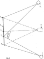
プレゼンターの影は、スクリーンの中心線の両側の約45°、かつスクリーンの中央の上に位置する2つの電子プロジェクタから画像を投影することによって消去される。各プロジェクタは、両方の画像がスクリーン上で重なり合い、整合するように直線的に補正するを備える。 Presenter shadows are eliminated by projecting images from two electronic projectors located approximately 45 ° on either side of the screen centerline and above the center of the screen. Each projector comprises a linear correction so that both images overlap and align on the screen.
赤外線カメラがプレゼンターの輪郭の位置を特定し、その輪郭からプレゼンターの質量中心が計算される。左のプロジェクタからの画像は、スクリーン上のプレゼンターの中心の真後ろの接合線の右に画像を投影しないように選択的に禁止される。右のプロジェクタは、接合線の左に画像を投影しないように同様に禁止される。2つのイメージ・セグメントは、プレゼンターの後ろで接合し、1つの完全な投影画像を形成する。 An infrared camera locates the presenter's contour, and the presenter's center of mass is calculated from the contour. The image from the left projector is selectively prohibited so as not to project the image to the right of the junction line just behind the center of the presenter on the screen. The right projector is similarly prohibited so as not to project an image to the left of the joint line. The two image segments are joined behind the presenter to form one complete projection image.
プレゼンターがスクリーンを横切って移動すると、画像の接合線がプレゼンターを追跡し、プレゼンターの後ろの位置を保つ。プレゼンターが少なくとも18インチ(約45.72cm)だけスクリーンから空間をとると、プレゼンターは全く影を落とさない。どちらのプロジェクタによっても照射される(眩しさを感じさせられる)ことのないプレゼンターは、楽に聴衆に直接目を向けることができる。 As the presenter moves across the screen, the splice line of the image tracks the presenter and keeps the position behind the presenter. If the presenter takes space from the screen by at least 18 inches (about 45.72 cm), the presenter will not cast any shadow. Presenters that are not illuminated by either projector (feeling dazzling) can easily look directly at the audience.
図1を参照すると、1つの電子画像プロジェクタが赤外線カメラと照明装置とともに点1に配置されている。第2の電子画像プロジェクタが赤外線カメラと照明装置とともに点6に配置されている。点1と6にある赤外線カメラと照明装置は、画像プロジェクタのすぐ下、またはすぐ上のごく接近したところに配置されている。プレゼンター7は、投影スクリーンから約18インチ(約45.72cm)以上離れている。図1では、点1と6の装置は、スクリーンの中央から約45°の角度で示され、天井に向かって持ち上げられている。部屋の形状と天井の高さによって、プロジェクタとカメラの配置のための点1と6の実際の位置が決められる。 Referring to FIG. 1, one electronic image projector is placed at point 1 along with an infrared camera and a lighting device. A second electronic image projector is located at point 6 along with an infrared camera and a lighting device. The infrared camera and illumination device at points 1 and 6 are located in close proximity just below or just above the image projector. Presenter 7 is more than about 18 inches (about 45.72 cm) away from the projection screen. In FIG. 1, the devices at points 1 and 6 are shown at an angle of about 45 ° from the center of the screen and are lifted towards the ceiling. Depending on the shape of the room and the height of the ceiling, the actual positions of points 1 and 6 for the placement of the projector and camera are determined.
2つの画像プロジェクタ(点1と6)は、水平面でスクリーンの中心から外れ、垂直方向にも偏心して部屋の天井付近に配置される。したがって、投影画像の直線補正(rectilinear correction)は両方の軸になされる。 The two image projectors (points 1 and 6) are disposed in the vicinity of the ceiling of the room, deviating from the center of the screen on a horizontal plane and decentering in the vertical direction. Thus, a rectilinear correction of the projected image is made on both axes.
写真技術では、偏心したカメラの直線補正は、物理的に正方形の物体の、物理的に正方形の写真画像を得るために、カメラレンズを水平面と垂直面で移動させることによって達成される。 In photographic technology, eccentric camera linear correction is accomplished by moving the camera lens in a horizontal and vertical plane to obtain a physically square photographic image of a physically square object.
電子プロジェクタの場合には、軸外し投影に対して補償する要求される画像の歪みは、画像が投影される前に画像を予め歪ませることによって電子的に達成される。 In the case of an electronic projector, the required image distortion to compensate for off-axis projection is achieved electronically by pre-distorting the image before it is projected.
赤外線照明装置は、近赤外線によって位置1と6から投影スクリーンを照明する小さな赤外線ランプと赤外線リフレクタである。位置1と6にある赤外線カメラは、位置1と6のそれぞれから認識されるプレゼンターの輪郭を定義する画素の検出を行なう。これらの2つの輪郭を使用して、その近似の中心の位置を特定するために、各輪郭の質量中心が計算される。この計算は、左右のカメラ・ビューから行なわれ、その2つの質量中心の平均は、プレゼンターの近似の質量中心になる。プレゼンターの近似の中心は、垂直接合線(vertical join line)の位置を特定するために使用される。 Infrared illumination devices are small infrared lamps and infrared reflectors that illuminate the projection screen from positions 1 and 6 with near infrared. The infrared cameras at positions 1 and 6 detect the pixels that define the outline of the presenter recognized from positions 1 and 6, respectively. Using these two contours, the center of mass of each contour is calculated to locate the approximate center. This calculation is done from the left and right camera views, and the average of the two centers of mass is the approximate center of mass of the presenter. The presenter's approximate center is used to locate the vertical join line.
2つのプロジェクタは、スクリーンのそれぞれの側に1つあり、それぞれが同じ画像をスクリーン上に投影する。直線補正を使用して、左画像は右のプロジェクタからの画像と重なり合い、整合する。左プロジェクタからの画像の一部は禁止される。残りの画像セグメントは、スクリーン上でプレゼンターの中心の後ろの垂直接合線の左のみに現れる。 There are two projectors, one on each side of the screen, each projecting the same image onto the screen. Using straight line correction, the left image overlaps and aligns with the image from the right projector. Part of the image from the left projector is prohibited. The remaining image segments appear only on the screen to the left of the vertical joint line behind the presenter center.
右のプロジェクタは、その画像セグメントがスクリーン上で垂直接合線の右のみに現れるように同様に禁止される。2つの画像セグメントは、プレゼンターの後ろの接合線のところで接する。 The right projector is similarly prohibited so that its image segment appears only on the screen to the right of the vertical join line. The two image segments meet at the joining line behind the presenter.
図1で理解できるように、プレゼンターがほぼ自身の体の幅でスクリーンの前に位置する場合、投影画像の左右のセグメントがプレゼンターの後ろで接合し、影を作らずに完全な画像を形成する。プレゼンターがスクリーンの前であちこちに移動すると、赤外線カメラがプレゼンターの位置を追跡する。したがって、2つの軸外しプロジェクタの接合線はプレゼンターの後を追い、後ろの位置を保つ。2つの画像は、プレゼンターの頭の上のスクリーン上でも接合する。 As can be seen in FIG. 1, when the presenter is positioned in front of the screen with its own body width, the left and right segments of the projected image join behind the presenter to form a complete image without creating shadows. . As the presenter moves around in front of the screen, an infrared camera tracks the position of the presenter. Therefore, the joint line of the two off-axis projectors follows the presenter and keeps the back position. The two images also join on the screen above the presenter's head.
各プロジェクタは、接合線を越えて投影しないように禁止されている。2つの赤外線カメラはそれぞれ、その個別の視点からプレゼンターの輪郭を生成する。各プロジェクタは、プレゼンターの輪郭領域内でも禁止されている。各画像セグメントの軸外し投影のため、両方の画像セグメントは、その画像をプレゼンターの上に投影しない。したがって、プレゼンターの輪郭領域内でどちらのプロジェクタも禁止する必要がないように見える。 Each projector is prohibited from projecting beyond the joint line. Each of the two infrared cameras generates the presenter's contour from its individual viewpoint. Each projector is also prohibited within the outline area of the presenter. Because of the off-axis projection of each image segment, both image segments do not project the image onto the presenter. Thus, it appears that neither projector needs to be prohibited within the presenter's contour region.
しかし、プレゼンターは、投影されたスクリーン画像のアイテムを特定するために指さす場合、いつでも自身の手や腕を伸ばして、どちらの投影ビーム(1〜3〜2、および6〜3〜5)にも入れることができる。しかし、プレゼンターの輪郭内で常に機能している禁止機能は、広げた手や腕の上に投影するのを防止する。スクリーンに近い手や腕は、大部分それ自体の影を覆う。 However, when presenters point to identify items in the projected screen image, they always stretch their hands and arms to either projection beam (1-3 to 2 and 6 to 3-5). Can be put. However, the forbidden function, which is always functioning within the presenter's outline, prevents it from being projected onto an open hand or arm. Hands and arms close to the screen mostly cover their own shadows.
軸外し投影用の直線補正を得るプロセスでは、広い軸外し投影角度のために、スクリーンの左右の縁部においての輝度は、等しくならない可能性があり、したがって、プレゼンターの頭部の上の接合線が目立つのを強調する。 In the process of obtaining a linear correction for off-axis projection, due to the wide off-axis projection angle, the luminance at the left and right edges of the screen may not be equal, and therefore the junction line on the presenter's head Emphasize that is conspicuous.
同一色であるが異なる輝度の2つの領域の接合は、2つの領域の間の輝度の差が1%のように小さい場合でも目立つ。輝度の不均一性は、直線補正、近くおよび遠くのスクリーン縁部に対する距離の違いがある広角の軸外し投影や、プロジェクタそれ自体の光学的緒特性により生じる。こうした全ての輝度の差異が結びついて、スクリーン上の輝度分布パターンと目立つ接合線を形成する。 The junction of two regions of the same color but different brightness is noticeable even when the difference in brightness between the two regions is as small as 1%. Brightness non-uniformity is caused by straight-line correction, wide-angle off-axis projection with different distances to near and far screen edges, and the optical characteristics of the projector itself. All these luminance differences combine to form a conspicuous bond line with the luminance distribution pattern on the screen.
均一なスクリーン輝度は、プロジェクタに供給される電子信号に白いフィールドを投影するときに、輝度分布パターンの逆(inverse)を加えることによって得られる。残存する、目立つ接合線があれば、一方の画像セグメントから他方への短いディゾルブ(dissolve)によって低減させることができる。 Uniform screen brightness is obtained by adding an inverse of the brightness distribution pattern when projecting a white field onto the electronic signal supplied to the projector. Any remaining noticeable joint lines can be reduced by a short dissolve from one image segment to the other.
投影スクリーンは、その表面が半艶消し仕上げの場合、目立った接合線を生じる可能性もある。艶消しの白いスクリーンは、180°の均一の輝度分布をもたらし、接合線を生じない。 Projection screens can also produce noticeable bond lines if their surface is semi-matte finished. A matte white screen provides a uniform brightness distribution of 180 ° and does not produce a bond line.
上述の手順により、プレゼンターがどちらの投影ビームも遮らずに、投影スクリーンの前でステージの両端の間を完全に自由に動けるようになる。2つのプロジェクタが各プロジェクタから確認されるプレゼンターの輪郭の内部で選択的に禁止されているので、投影画像は、プレゼンターの上に映されることはない。これは、プレゼンターにプロジェクタ・レンズの眩しく感じさせるグレアを見ないことも意味する。プレゼンターは、眩しく感じさせる投影のグレアなしに、自身の聴衆に向かって楽に目を向けることができる。 The above procedure allows the presenter to move freely between the ends of the stage in front of the projection screen without blocking either projection beam. Since the two projectors are selectively prohibited within the presenter's outline as seen from each projector, the projected image will not be projected on the presenter. This also means not seeing glare that makes the presenter feel the glare of the projector lens. Presenters can easily look to their audience without glare in projected glare.
視聴者は、中心から外れて着座すると、通常はプレゼンターの影を認識する。二重投影により、聴衆は影を全く認識しない。プレゼンターが投影スクリーンの前に立ち入ると、視聴者は通常は、投影画像の気になる歪みを認識する。偏心投影や選択的な禁止により、プレゼンターがどちらの投影ビームの中に腕を伸ばした場合にも、投影画像はプレゼンターの上に全く映されない。 The viewer usually recognizes the shadow of the presenter when seated off the center. Due to the double projection, the audience does not recognize the shadow at all. When the presenter enters the front of the projection screen, the viewer typically recognizes the distortion of the projected image. Due to eccentric projection or selective prohibition, no projection image is projected on the presenter when the presenter extends his arm into either projection beam.
プレゼンターの輪郭は、それぞれのプロジェクタから認識されるように正確にプレゼンターの領域を定義し、これらの画素は禁止される(すなわち黒色にされる)。次いで、これらの同じ画素は、選択された照明信号を割り当てられる。この信号は、暗くされた講堂内でプレゼンターの低レベルの補助照明を与える。この補助照明はある輝度レベルを割り当てられ、所望であれば色を割り当てられる。この補助照明は、プレゼンターを越えて広がることはなく、したがって投影されたスクリーン画像に色あせを与えることがない。 The presenter's outline defines the region of the presenter exactly as recognized by the respective projectors, and these pixels are forbidden (ie blackened). These same pixels are then assigned the selected illumination signal. This signal gives the presenter a low level of auxiliary lighting in the darkened auditorium. This auxiliary illumination is assigned a certain luminance level and is assigned a color if desired. This auxiliary illumination does not spread beyond the presenter and therefore does not fade the projected screen image.
2つのプロジェクタが部屋の側面に対して高く、良好に配置された場合、プレゼンターは、2つのプロジェクタから補助照明を受け取る場合でも、自分の聴衆に比較的楽に目を向けることができる。 If the two projectors are high and well positioned with respect to the side of the room, the presenter can relatively easily look to his audience even when receiving auxiliary lighting from the two projectors.
代替形態
影のない投影を実現する好ましい方法を上記に説明してきた。1つのみの赤外線カメラと照明装置を使用する別の実施形態が図2に示されている。赤外線カメラ9は、質量中心を計算するためのプレゼンターの輪郭を検出する。プレゼンターの中央のすぐ後ろの投影スクリーン上の点3の位置を特定するのに使用されるのはこの質量中心である。投影画像の左右の部分は、スクリーン上のプレゼンターの後ろの点3で接合し、この接合線は、プレゼンターがスクリーンの前であちこちに移動するとプレゼンターを追跡する。
Alternatives Preferred methods for achieving shadowless projection have been described above. Another embodiment using only one infrared camera and illumination device is shown in FIG. The infrared camera 9 detects the contour of the presenter for calculating the center of mass. It is this center of mass that is used to locate the
この単一のカメラ9は、プレゼンターの位置を追跡するのに満足のいくものであり、投影の接合線3を確立する。位置9から生成された禁止信号は、プロジェクタの位置1と6から認識されるプレゼンターの輪郭とは一致しない。したがって、単一の中央の赤外線カメラ9から認識されるプレゼンターの輪郭は、プレゼンターの腕がどちらの投影ビームの中に伸ばされた場合にも、腕の上への投影を禁止するのに使用できない。
This single camera 9 is satisfactory for tracking the position of the presenter and establishes the
1つだけの赤外線カメラと照明装置を有するこのシステムは、より費用がかからず、ほとんどの用途に対して非常に満足のいくものである。プレゼンターの体にプロジェクタの光が全く映されないので、プレゼンターは、プロジェクタの眩しいグレアに悩まされずに、自身の聴衆に直接目を向けることができる。 This system with only one infrared camera and lighting device is less expensive and very satisfactory for most applications. Since no light from the projector is projected on the presenter's body, the presenter can look directly at his audience without suffering from the glare of the projector.
図3は、自動的に焦点距離を決定するためにある種のカメラに使用されるような、スクリーンの一方の縁部にある距離計10の使用を示す。このデバイスは、スクリーン縁部に対してプレゼンター7の近い縁部に対する距離を検出するために適している。距離計の示す距離にプレゼンターの体の半分の幅を加えることは、近似の質量中心の位置を特定し、プレゼンターの後ろの接合線の位置を特定するために許容できる。 FIG. 3 illustrates the use of a distance meter 10 at one edge of the screen, such as used in certain cameras to automatically determine the focal length. This device is suitable for detecting the distance to the near edge of the presenter 7 relative to the screen edge. Adding half the width of the presenter's body to the distance indicated by the rangefinder is acceptable to determine the location of the approximate center of mass and the location of the junction line behind the presenter.
距離計オプションは、プレゼンターの後ろの接合線の位置を特定するために、図2の単一の赤外線カメラよりも費用がかからない可能性がある。スクリーンの反対側の縁部に配置された第2の距離計は、非常に広いスクリーンのための距離の正確さを向上させる。距離計は、その中では測定しない最小の距離範囲を有するので、距離計は少なくともその距離だけスクリーン縁部を越えて配置されるべきである。 The rangefinder option may be less expensive than the single infrared camera of FIG. 2 to locate the junction line behind the presenter. A second rangefinder located at the opposite edge of the screen improves distance accuracy for very wide screens. The rangefinder has the smallest range of distances it will not measure, so the rangefinder should be placed at least that distance beyond the screen edge.
図2の中央の単一の赤外線カメラの場合のように、図3の距離計オプションは、スクリーンに影を作らない改善された投影システムをもたらす。距離計は、プレゼンターがスクリーンの前をあちこちに移動すると二重プロジェクタがプレゼンターを追跡し、プレゼンターの後ろでその投影画像セグメントを接合することができるようにする。プロジェクタの光がプレゼンターに全く映されないので、プレゼンターは、プロジェクタの眩しいグレアに悩まされずに自身の聴衆にまっすぐに目を向けることができる。 As with the single infrared camera in the center of FIG. 2, the rangefinder option of FIG. 3 results in an improved projection system that does not cast shadows on the screen. The rangefinder allows the dual projector to track the presenter as the presenter moves around in front of the screen and join its projected image segments behind the presenter. Since no light from the projector is projected to the presenter, the presenter can look straight into his audience without suffering from the glare of the projector.
Claims (17)
b)前記プレゼンターの輪郭の質量中心を得るステップと、
c)前記プレゼンターの質量中心のすぐ後ろの前記スクリーン上の垂直接合線の位置を特定するステップと、
d)前記接合線の右に広がる、前記第1のプロジェクタからの投影画像の部分を禁止するステップと、
e)前記接合線の左に広がる、前記第2のプロジェクタからの投影画像の部分を禁止するステップとからなり、
前記ステップd)とe)において投影が禁止されない、前記接合線の左に広がる、前記第1のプロジェクタからの投影画像の部分と前記接合線の右に広がる、前記第2のプロジェクタからの投影画像の部分とからスクリーン上に完全な投影画像が生成されることを特徴とする投影方法。from each of two positions of a) images off-axis on either side of the center line of the screen to be projected, the left and right of the projected image from the first and second projectors that will be projected simultaneously on the screen, both of the image a step of projecting a is corrected using the first and second projectors to match on the screen as a single image,
b) obtaining the center of mass of the contour of the presenter;
c) locating a vertical bond line on the screen immediately behind the center of mass of the presenter;
d) prohibiting a portion of the projected image from the first projector that extends to the right of the joint line;
e) prohibiting a portion of the projected image from the second projector that extends to the left of the joint line;
In step d) and e), projection is not prohibited, a portion of the projection image from the first projector that extends to the left of the joint line and a projection image from the second projector that extends to the right of the joint line A projection method characterized in that a complete projection image is generated on the screen from the above portion .
Applications Claiming Priority (2)
| Application Number | Priority Date | Filing Date | Title |
|---|---|---|---|
| US10/754,147 US6860604B1 (en) | 2004-01-09 | 2004-01-09 | Method and apparatus for inhibiting the projection of a shadow of a presenter onto a projection screen |
| PCT/US2004/038350 WO2005072010A1 (en) | 2004-01-09 | 2004-11-15 | Method and apparatus for inhibiting the projection of a shadow of a presenter onto a projection screen |
Publications (3)
| Publication Number | Publication Date |
|---|---|
| JP2007520945A JP2007520945A (en) | 2007-07-26 |
| JP2007520945A5 JP2007520945A5 (en) | 2007-11-22 |
| JP4653117B2 true JP4653117B2 (en) | 2011-03-16 |
Family
ID=34194988
Family Applications (1)
| Application Number | Title | Priority Date | Filing Date |
|---|---|---|---|
| JP2006549252A Expired - Fee Related JP4653117B2 (en) | 2004-01-09 | 2004-11-15 | Method and apparatus for inhibiting presenter shadows from being projected onto a projection screen |
Country Status (8)
| Country | Link |
|---|---|
| US (1) | US6860604B1 (en) |
| EP (1) | EP1709481A4 (en) |
| JP (1) | JP4653117B2 (en) |
| KR (1) | KR101142105B1 (en) |
| CN (1) | CN100592198C (en) |
| MY (1) | MY134417A (en) |
| TW (1) | TWI276905B (en) |
| WO (1) | WO2005072010A1 (en) |
Families Citing this family (22)
| Publication number | Priority date | Publication date | Assignee | Title |
|---|---|---|---|---|
| WO2006020661A2 (en) * | 2004-08-10 | 2006-02-23 | Nicholson Bruce A | Sodium screen digital traveling matte methods and apparatus |
| US20060170871A1 (en) * | 2005-02-01 | 2006-08-03 | Dietz Paul H | Anti-blinding safety feature for projection systems |
| US20070018989A1 (en) * | 2005-07-20 | 2007-01-25 | Playmotion, Llc | Sensory integration therapy system and associated method of use |
| US7984995B2 (en) * | 2006-05-24 | 2011-07-26 | Smart Technologies Ulc | Method and apparatus for inhibiting a subject's eyes from being exposed to projected light |
| JP5023587B2 (en) * | 2006-07-18 | 2012-09-12 | 富士ゼロックス株式会社 | Image display device and image display method |
| JP4270264B2 (en) * | 2006-11-01 | 2009-05-27 | セイコーエプソン株式会社 | Image correction apparatus, projection system, image correction method, image correction program, and recording medium |
| US20090124382A1 (en) * | 2007-11-13 | 2009-05-14 | David Lachance | Interactive image projection system and method |
| JP2009193058A (en) * | 2008-01-18 | 2009-08-27 | Seiko Epson Corp | Projection system and projector |
| WO2011013240A1 (en) * | 2009-07-31 | 2011-02-03 | Necディスプレイソリューションズ株式会社 | Projection display device and light quantity adjusting method |
| JP5596427B2 (en) * | 2010-06-09 | 2014-09-24 | 日本電信電話株式会社 | Optical projection control method, optical projection control apparatus, optical projection control system, and program |
| JP5170176B2 (en) * | 2010-06-30 | 2013-03-27 | ソニー株式会社 | Object judgment system, object judgment method and program |
| CN102385238B (en) * | 2010-09-03 | 2015-07-01 | 深圳华强数码电影有限公司 | Implementation method and system for projecting and showing of ball screen |
| JP2012249008A (en) * | 2011-05-26 | 2012-12-13 | Nippon Telegr & Teleph Corp <Ntt> | Multiplex projection control apparatus, multiplex projection control method and multiplex projection control program |
| US9197870B1 (en) | 2012-09-12 | 2015-11-24 | Amazon Technologies, Inc. | Automatic projection focusing |
| JP6410079B2 (en) * | 2014-06-26 | 2018-10-24 | パナソニックIpマネジメント株式会社 | Optical projection device and illumination device using the same |
| US10718670B2 (en) * | 2015-03-23 | 2020-07-21 | The Trustees Of Princeton University | Spherical-motion average radiant temperature sensor |
| CN104954713B (en) * | 2015-06-16 | 2018-10-12 | 苏州佳世达光电有限公司 | A kind of eye shield projection method and splicing projection arrangement |
| CN105245804A (en) * | 2015-09-06 | 2016-01-13 | 联想(北京)有限公司 | Information processing method and electronic equipment |
| CN106817550B (en) * | 2015-12-01 | 2022-06-03 | 中兴通讯股份有限公司 | Projection method and device of projector |
| CN106791747A (en) * | 2017-01-25 | 2017-05-31 | 触景无限科技(北京)有限公司 | The time-sharing handling method of desk lamp interaction display, device and desk lamp |
| JP2021144472A (en) * | 2020-03-12 | 2021-09-24 | ソニーグループ株式会社 | Information processing system, information processing method, and program |
| CN111586386A (en) * | 2020-06-01 | 2020-08-25 | 光峰光电(无锡)有限公司 | Ultra-short-focus projection method capable of automatically focusing and bidirectionally correcting trapezoid |
Citations (5)
| Publication number | Priority date | Publication date | Assignee | Title |
|---|---|---|---|---|
| JPH07162743A (en) * | 1993-12-03 | 1995-06-23 | Matsushita Electric Ind Co Ltd | Image processor for projector, and projector |
| JP2001339671A (en) * | 2000-05-29 | 2001-12-07 | Matsushita Electric Ind Co Ltd | Projector device |
| JP2002107831A (en) * | 2000-09-28 | 2002-04-10 | Nippon Hoso Kyokai <Nhk> | Rear projection type multiscreen display |
| WO2002067049A1 (en) * | 2001-02-16 | 2002-08-29 | Imatte, Inc. | Method and apparatus for inhibiting projection of selected areas of a projected image |
| JP2003177466A (en) * | 2001-08-21 | 2003-06-27 | Hae Yong Choi | Wide-visual-field and high-luminance video system |
Family Cites Families (3)
| Publication number | Priority date | Publication date | Assignee | Title |
|---|---|---|---|---|
| US5270820A (en) * | 1992-06-25 | 1993-12-14 | Ultimatte Corporation | Method and apparatus for tracking a pointing device in a video field |
| GB9608770D0 (en) * | 1996-04-27 | 1996-07-03 | Philips Electronics Nv | Projection display system |
| KR20020001107A (en) * | 2000-06-26 | 2002-01-09 | 이형도 | Video camera for computer |
-
2004
- 2004-01-09 US US10/754,147 patent/US6860604B1/en not_active Expired - Fee Related
- 2004-11-15 EP EP04811166A patent/EP1709481A4/en not_active Withdrawn
- 2004-11-15 WO PCT/US2004/038350 patent/WO2005072010A1/en active Application Filing
- 2004-11-15 CN CN200480040038A patent/CN100592198C/en not_active Expired - Fee Related
- 2004-11-15 KR KR1020067013791A patent/KR101142105B1/en not_active IP Right Cessation
- 2004-11-15 JP JP2006549252A patent/JP4653117B2/en not_active Expired - Fee Related
- 2004-11-24 TW TW093136108A patent/TWI276905B/en not_active IP Right Cessation
- 2004-11-30 MY MYPI20044960A patent/MY134417A/en unknown
Patent Citations (5)
| Publication number | Priority date | Publication date | Assignee | Title |
|---|---|---|---|---|
| JPH07162743A (en) * | 1993-12-03 | 1995-06-23 | Matsushita Electric Ind Co Ltd | Image processor for projector, and projector |
| JP2001339671A (en) * | 2000-05-29 | 2001-12-07 | Matsushita Electric Ind Co Ltd | Projector device |
| JP2002107831A (en) * | 2000-09-28 | 2002-04-10 | Nippon Hoso Kyokai <Nhk> | Rear projection type multiscreen display |
| WO2002067049A1 (en) * | 2001-02-16 | 2002-08-29 | Imatte, Inc. | Method and apparatus for inhibiting projection of selected areas of a projected image |
| JP2003177466A (en) * | 2001-08-21 | 2003-06-27 | Hae Yong Choi | Wide-visual-field and high-luminance video system |
Also Published As
| Publication number | Publication date |
|---|---|
| US6860604B1 (en) | 2005-03-01 |
| EP1709481A4 (en) | 2008-06-18 |
| KR20060126702A (en) | 2006-12-08 |
| JP2007520945A (en) | 2007-07-26 |
| CN100592198C (en) | 2010-02-24 |
| KR101142105B1 (en) | 2012-05-08 |
| TW200523658A (en) | 2005-07-16 |
| WO2005072010A9 (en) | 2006-03-30 |
| MY134417A (en) | 2007-12-31 |
| WO2005072010A1 (en) | 2005-08-04 |
| TWI276905B (en) | 2007-03-21 |
| CN1902544A (en) | 2007-01-24 |
| EP1709481A1 (en) | 2006-10-11 |
Similar Documents
| Publication | Publication Date | Title |
|---|---|---|
| JP4653117B2 (en) | Method and apparatus for inhibiting presenter shadows from being projected onto a projection screen | |
| US8311366B2 (en) | System and method for calibrating and adjusting a projected image of a projection apparatus | |
| US7468778B2 (en) | Virtual studio system | |
| JP2007520945A5 (en) | ||
| WO2006041834A3 (en) | Interactive projection system and method | |
| CA2438724A1 (en) | Method and apparatus for inhibiting projection of selected areas of a projected image | |
| EP2193311B1 (en) | Method of illuminating a 3d object with a modified 2d image of the 3d object by means of a projector, and projector suitable for performing such a method | |
| EP0876055B1 (en) | Method of providing background patterns for camera tracking | |
| JP2006522559A (en) | Facilities and methods to enable eye contact between video conference participants | |
| JP2002236332A (en) | Stereoscopic adapter, pattern projection adapter and adapter for light emitting member | |
| JPH05107639A (en) | Projection type liquid crystal projector | |
| US4527872A (en) | Composite process cinematography system and method | |
| US20210124154A1 (en) | Method and apparatus for optical projection | |
| US6956611B2 (en) | Projection apparatus and phototaking apparatus having the same | |
| JP3053089U (en) | Wide-angle projection on a dome screen using a combination of a spherical mirror and a video projector | |
| JP2005031270A (en) | Video image projection device for dome screen | |
| JP2002054913A (en) | Three-dimensional data generating system and projector | |
| JPH09325263A (en) | Light projection system for automatic focus detection | |
| JP2007166280A (en) | Projector, screen for projector and projector image display system | |
| JP2024044350A (en) | Control device, image projection system, control method, and program | |
| JP2003280092A (en) | Multi-projection display device | |
| JPH02172380A (en) | Video projector | |
| SU159308A1 (en) | ||
| JPH07311016A (en) | Method and device for measuring dimension of object | |
| JP2001083403A (en) | Light projection optical system for detecting focus |
Legal Events
| Date | Code | Title | Description |
|---|---|---|---|
| A521 | Written amendment |
Free format text: JAPANESE INTERMEDIATE CODE: A523 Effective date: 20071001 |
|
| A621 | Written request for application examination |
Free format text: JAPANESE INTERMEDIATE CODE: A621 Effective date: 20071001 |
|
| A977 | Report on retrieval |
Free format text: JAPANESE INTERMEDIATE CODE: A971007 Effective date: 20100602 |
|
| A131 | Notification of reasons for refusal |
Free format text: JAPANESE INTERMEDIATE CODE: A131 Effective date: 20100622 |
|
| A521 | Written amendment |
Free format text: JAPANESE INTERMEDIATE CODE: A523 Effective date: 20100916 |
|
| TRDD | Decision of grant or rejection written | ||
| A01 | Written decision to grant a patent or to grant a registration (utility model) |
Free format text: JAPANESE INTERMEDIATE CODE: A01 Effective date: 20101116 |
|
| A01 | Written decision to grant a patent or to grant a registration (utility model) |
Free format text: JAPANESE INTERMEDIATE CODE: A01 |
|
| A61 | First payment of annual fees (during grant procedure) |
Free format text: JAPANESE INTERMEDIATE CODE: A61 Effective date: 20101216 |
|
| R150 | Certificate of patent or registration of utility model |
Free format text: JAPANESE INTERMEDIATE CODE: R150 |
|
| FPAY | Renewal fee payment (event date is renewal date of database) |
Free format text: PAYMENT UNTIL: 20131224 Year of fee payment: 3 |
|
| R250 | Receipt of annual fees |
Free format text: JAPANESE INTERMEDIATE CODE: R250 |
|
| R250 | Receipt of annual fees |
Free format text: JAPANESE INTERMEDIATE CODE: R250 |
|
| R250 | Receipt of annual fees |
Free format text: JAPANESE INTERMEDIATE CODE: R250 |
|
| R250 | Receipt of annual fees |
Free format text: JAPANESE INTERMEDIATE CODE: R250 |
|
| LAPS | Cancellation because of no payment of annual fees |