JP4652532B2 - TDMA communication apparatus and communication method thereof - Google Patents
TDMA communication apparatus and communication method thereof Download PDFInfo
- Publication number
- JP4652532B2 JP4652532B2 JP2000217060A JP2000217060A JP4652532B2 JP 4652532 B2 JP4652532 B2 JP 4652532B2 JP 2000217060 A JP2000217060 A JP 2000217060A JP 2000217060 A JP2000217060 A JP 2000217060A JP 4652532 B2 JP4652532 B2 JP 4652532B2
- Authority
- JP
- Japan
- Prior art keywords
- equipment unit
- local
- delay
- message
- tone
- Prior art date
- Legal status (The legal status is an assumption and is not a legal conclusion. Google has not performed a legal analysis and makes no representation as to the accuracy of the status listed.)
- Expired - Fee Related
Links
Images


Classifications
-
- H—ELECTRICITY
- H04—ELECTRIC COMMUNICATION TECHNIQUE
- H04N—PICTORIAL COMMUNICATION, e.g. TELEVISION
- H04N7/00—Television systems
- H04N7/22—Adaptations for optical transmission
-
- H—ELECTRICITY
- H04—ELECTRIC COMMUNICATION TECHNIQUE
- H04J—MULTIPLEX COMMUNICATION
- H04J3/00—Time-division multiplex systems
- H04J3/02—Details
- H04J3/06—Synchronising arrangements
- H04J3/0635—Clock or time synchronisation in a network
- H04J3/0682—Clock or time synchronisation in a network by delay compensation, e.g. by compensation of propagation delay or variations thereof, by ranging
-
- H—ELECTRICITY
- H04—ELECTRIC COMMUNICATION TECHNIQUE
- H04L—TRANSMISSION OF DIGITAL INFORMATION, e.g. TELEGRAPHIC COMMUNICATION
- H04L7/00—Arrangements for synchronising receiver with transmitter
- H04L7/04—Speed or phase control by synchronisation signals
- H04L7/06—Speed or phase control by synchronisation signals the synchronisation signals differing from the information signals in amplitude, polarity or frequency or length
-
- H—ELECTRICITY
- H04—ELECTRIC COMMUNICATION TECHNIQUE
- H04N—PICTORIAL COMMUNICATION, e.g. TELEVISION
- H04N7/00—Television systems
- H04N7/16—Analogue secrecy systems; Analogue subscription systems
- H04N7/173—Analogue secrecy systems; Analogue subscription systems with two-way working, e.g. subscriber sending a programme selection signal
- H04N7/17309—Transmission or handling of upstream communications
-
- H—ELECTRICITY
- H04—ELECTRIC COMMUNICATION TECHNIQUE
- H04N—PICTORIAL COMMUNICATION, e.g. TELEVISION
- H04N7/00—Television systems
- H04N7/16—Analogue secrecy systems; Analogue subscription systems
- H04N7/173—Analogue secrecy systems; Analogue subscription systems with two-way working, e.g. subscriber sending a programme selection signal
- H04N2007/17381—Analogue secrecy systems; Analogue subscription systems with two-way working, e.g. subscriber sending a programme selection signal the upstream transmission being initiated by the user terminal
Landscapes
- Engineering & Computer Science (AREA)
- Signal Processing (AREA)
- Computer Networks & Wireless Communication (AREA)
- Multimedia (AREA)
- Small-Scale Networks (AREA)
- Time-Division Multiplex Systems (AREA)
Description
【0001】
【発明の属する技術分野】
本発明は、時分割多元接続(TDMA)通信に関し、特に、TDMAの送信におけるレンジング(ranging)に関する。
【0002】
【従来の技術】
【0003】
TDMAにおいて信号を伝送する場合には、TDMA伝送の個々の信号成分がすべて同一の伝送遅延をもつことが必要である。このため、TDMA伝送に含まれるそれぞれの信号に対して遅延期間を決定しなければならず、個々の信号に遅延期間を加算したとき、その信号には、TDMAの他の信号成分における個々の折り返し遅延に等しい共通の折り返し遅延が生じる。
【0004】
信号を伝送する任意の機器ユニットが配置されたとき、若しくは再配置されたとき、又はサービスができなくなったときに、TDMAのそれぞれの信号成分に加算される固有の遅延を決定するためには、いわゆる「レンジング」手順が実行される。よく知られている従来の一般的なレンジング手順として、いわゆる「インバンド(帯域内)・レンジング」がある。インバンド・レンジング・メッセージが、このインバンド・レンジングを実行するために用いられる。
【0005】
しかしながら、このインバンド・レンジング・メッセージを用いるには、伝送帯域に一時的に割り込んで、インバンド・レンジング・メッセージを伝送する必要がある。したがって、インバンド・レンジングは通常の帯域使用を妨げてしまう侵入的な手順である。その上、インバンド・レンジングを実行するときにはスケジュールを立てる必要がある。事実、インバンド・レンジングのスケジュールの比率が多くなればなるほど、伝送帯域の喪失も大きくなる。このことは極めて望ましからざることである。なぜなら、この帯域は他の目的、例えば固定速度の伝送の目的には使用できないからである。
【0006】
【発明が解決しようとする課題】
本発明は、このような従来の公知のインバンド・レンジングの問題、及び従来のインバンド・レンジングの他の問題や限界を解決するものであり、TDMAの通信装置、システム、及び通信方法を提供することを目的とする。本発明の概略は次のようなものである。
【0007】
不可侵的なアウトバンド(帯域外)・レンジング技術を使用する。レンジングが自動的に顧客機器ユニットの初期化を行うのは、機器が配置されたとき、電源が停電したり若しくは一時的に中断した後に再び復元したとき、機器の検証のとき、機器が切断した後に再接続されたとき、又はその他の場合である。このために、アウトバンド・トーンが用いられ、TDMA信号を伝送する顧客機器の電源がオンされたとき、又は、ローカル的若しくはリモート的に発生された特定のコマンドに応じて送信がされたときに、そのアウトバンド・トーンが送信される。
【0008】
特に、レンジングが実行されるときは、顧客機器がアウトバンド・レンジング・トーンを発生して送信し、リモート端末からレンジング・トーンの送信を終了した旨を表現するメッセージを受信するまでである。決定される折り返し遅延は、終了メッセージの送信から、レンジング・トーンの終了を検出するまでの遅延期間である。そして、顧客機器に送信されるメッセージは、レンジング・遅延期間を含み、これ以降にリモート端末に送信される場合にすべて使用される。
【0009】
この発明の一実施形態においては、顧客機器が自動的にアイドル待機状態に遷移するのは、リモート端末が自分の上り送信スロットを取り去るときである。顧客機器は、待機状態においてもなおデータ受信の能力があり、上り送信スロットにデータを割り当てたリモート端末によって周期的にポーリングされる。待機状態にある顧客機器があらかじめ設定された期間の間にポーリングされない場合には、その顧客機器は自動的に検証状態に遷移する。
【0010】
さらに、顧客機器がポーリングに応答しない場合には、リモート端末は検証状態においてその旨を含めたメッセージをその顧客機器に送信する。ポーリングされた顧客機器がアウトバンド・トーンに応答して検証状態にあることを表現した場合には、リモート端末はその顧客機器を検証中のレンジングと見なして取り扱う。アウトバンド・トーンが適正に合わさった場合には、顧客機器はアクティブ状態に遷移される。
【0011】
アイドル待機状態におけるポーリング顧客機器の利点は、アイドル顧客機器、停電、切断された若しくは取り去られた顧客機器をシステム動作が識別できることである。
【0012】
【課題を解決するための手段】
本発明は、少なくとも1つのローカル機器ユニット及び規定されたリモート位置におけるリモート機器ユニットの間における信号伝播の遅延期間を得るために少なくとも1つのローカル機器ユニットにおいて使用する装置であって、
a)ローカル機器ユニットの電源がオンであるか否かの指示を供給する指示器と、
b)レンジング遅延期間を確立することにより少なくとも1つのローカル機器ユニットが初期化されているか否かを示すために電力オン指示に応答する指示器と、
c)少なくとも1つのローカル機器ユニットが初期化されていないことの指示に応答して、前記少なくとも1つのローカル機器ユニットから前記リモート機器ユニットに対してデータ信号が送信される周波数帯域以外の周波数帯域においてアウトバンド・レンジング遅延・トーンを送信する制御可能な送信機と、
d)前記アウトバンド・レンジング遅延・トーン・メッセージの送信を終了する制御可能な送信機を制御する前記リモート機器ユニットからアウトバンド・レンジング遅延・トーン・メッセージの送信停止を受信し、前記少なくとも1つのローカル機器ユニットから前記リモート機器ユニットに送信されるインバンド・データ信号に適用される遅延期間の表現を有するメッセージを受信する受信機と、
からなるTDMAの通信装置を提供する。
【0013】
本発明は、リモート機器ユニット及びローカル位置における少なくとも1つのローカル機器ユニットの間における信号伝播の遅延期間を発生するために規定されたリモート位置におけるリモート機器ユニットにおいて使用する装置であって、
a)アウトバンド・レンジング遅延・トーンの受信を検出する検出器と、
b)前記レンジング遅延・トーンの受信の検出に応答して、前記レンジング遅延・トーンの送信を終了するために前記少なくとも1つのローカル機器ユニットに対して終了メッセージを送信し、前記少なくとも1つのローカル機器ユニットに対してレンジング遅延期間の表現を有するメッセージを送信する送信機と、
c)前記終了メッセージを送信したときに開始し前記レンジング遅延・トーンの終了を受信したことを前記検出器が検出したときに停止し、前記開始から前記停止までの期間を前記レンジング遅延期間とする遅延タイマと、
からなるTDMAの通信装置を提供する。
【0014】
本発明は、 少なくとも1つのローカル機器ユニット及び規定されたリモート位置におけるリモート機器ユニットの間における信号伝播の遅延期間を得るために少なくとも1つのローカル機器ユニットにおいて使用する装置であって、
a)ローカル機器ユニットの電源がオンであるか否かの指示を供給する手段と、
b)レンジング遅延期間を確立することにより少なくとも1つのローカル機器ユニットが初期化されているか否かを示すために電力オン指示に応答する手段と、
c)少なくとも1つのローカル機器ユニットが初期化されていないことの指示に応答して、前記少なくとも1つのローカル機器ユニットから前記リモート機器ユニットに対してデータ信号が送信される周波数帯域以外の周波数帯域においてアウトバンド・レンジング遅延・トーンを送信する手段と、
d)前記アウトバンド・レンジング遅延・トーン・メッセージの送信を終了する制御可能な送信機を制御する前記リモート機器ユニットからアウトバンド・レンジング遅延・トーン・メッセージの送信停止を受信し、前記少なくとも1つのローカル機器ユニットから前記リモート機器ユニットに送信されるインバンド・データ信号に適用される遅延期間の表現を有するメッセージを受信する手段と、
からなるTDMAの通信装置を提供する。
【0015】
本発明は、リモート機器ユニット及びローカル位置における少なくとも1つのローカル機器ユニットの間における信号伝播の遅延期間を発生するために規定されたリモート位置におけるリモート機器ユニットにおいて使用する装置であって、
a)アウトバンド・レンジング遅延・トーンの受信を検出する手段と、
b)前記レンジング遅延・トーンの受信の検出に応答して、前記レンジング遅延・トーンの送信を終了するために前記少なくとも1つのローカル機器ユニットに対して終了メッセージを送信し、前記少なくとも1つのローカル機器ユニットに対してレンジング遅延期間の表現を有するメッセージを送信する手段と、
c)前記終了メッセージを送信したときに開始し前記レンジング遅延・トーンの終了を受信したことを前記検出器が検出したときに停止し、前記開始から前記停止までの期間を前記レンジング遅延期間とする遅延タイマと、
からなるTDMAの通信装置を提供する。
【0016】
本発明は、少なくとも1つのローカル機器ユニット及びリモート機器ユニットの間における信号伝播の遅延期間を得るために少なくとも1つのローカル機器ユニット及びリモート機器ユニットを有するシステムに使用する装置であって、
前記少なくとも1つのローカル機器ユニットにおいて使用するための、
a)ローカル機器ユニットの電源がオンであるか否かの指示を供給する指示器と、
b)レンジング遅延期間を確立することにより少なくとも1つのローカル機器ユニットが初期化されているか否かを示すために電力オン指示に応答する指示器と、
c)少なくとも1つのローカル機器ユニットが初期化されていないことの指示に応答して、前記少なくとも1つのローカル機器ユニットから前記リモート機器ユニットに対してデータ信号が送信される周波数帯域以外の周波数帯域においてアウトバンド・レンジング遅延・トーンを送信する制御可能な送信機と、
d)前記アウトバンド・レンジング遅延・トーン・メッセージの送信を終了する制御可能な送信機を制御する前記リモート機器ユニットからアウトバンド・レンジング遅延・トーン・メッセージの送信停止を受信し、前記少なくとも1つのローカル機器ユニットから前記リモート機器ユニットに送信されるインバンド・データ信号に適用される遅延期間の表現を有するメッセージを受信するローカル受信機と、
前記リモート機器ユニットに使用するための、
e)アウトバンド・レンジング遅延・トーンの受信を検出する検出器と、
f)前記レンジング遅延・トーンの受信の検出に応答して、前記レンジング遅延・トーンの送信を終了するために前記少なくとも1つのローカル機器ユニットに対して終了メッセージを送信し、前記少なくとも1つのローカル機器ユニットに対してレンジング遅延期間の表現を有するメッセージを送信するローカル送信機と、
g)前記終了メッセージを送信したときに開始し前記レンジング遅延・トーンの終了を受信したことを前記検出器が検出したときに停止し、前記開始から前記停止までの期間を前記レンジング遅延期間とする遅延タイマと、
からなるTDMAの通信装置を提供する。
【0017】
本発明は、少なくとも1つのローカル機器ユニット及び規定されたリモート位置におけるリモート機器ユニットの間における信号伝播の遅延期間を得るために少なくとも1つのローカル機器ユニットにおいて使用する方法であって、
a)ローカル機器ユニットの電源がオンであるか否かの指示を供給するステップと、
b)レンジング遅延期間を確立することにより少なくとも1つのローカル機器ユニットが初期化されているか否かを示すために電力オン指示に応答するステップと、
c)少なくとも1つのローカル機器ユニットが初期化されていないことの指示に応答して、前記少なくとも1つのローカル機器ユニットから前記リモート機器ユニットに対してデータ信号が送信される周波数帯域以外の周波数帯域においてアウトバンド・レンジング遅延・トーンを送信する制御可能なステップと、
d)前記アウトバンド・レンジング遅延・トーン・メッセージの送信を終了する制御可能な送信機を制御する前記リモート機器ユニットからアウトバンド・レンジング遅延・トーン・メッセージの送信停止を受信し、前記少なくとも1つのローカル機器ユニットから前記リモート機器ユニットに送信されるインバンド・データ信号に適用される遅延期間の表現を有するメッセージを受信するステップと、
からなるTDMAの通信方法を提供する。
【0018】
本発明は、リモート機器ユニット及びローカル位置における少なくとも1つのローカル機器ユニットの間における信号伝播の遅延期間を発生するために規定されたリモート位置におけるリモート機器ユニットにおいて使用する方法であって、
a)アウトバンド・レンジング遅延・トーンの受信を検出するステップと、
b)前記レンジング遅延・トーンの受信の検出に応答して、前記レンジング遅延・トーンの送信を終了するために前記少なくとも1つのローカル機器ユニットに対して終了メッセージを送信し、前記少なくとも1つのローカル機器ユニットに対してレンジング遅延期間の表現を有するメッセージを送信するステップと、
c)前記終了メッセージを送信したときに開始し前記レンジング遅延・トーンの終了を受信したことを前記検出器が検出したときに停止し、前記開始から前記停止までの期間を前記レンジング遅延期間とする遅延タイマを制御するステップと、
からなるTDMAの通信方法を提供する。
【0019】
本発明は、少なくとも1つのローカル機器ユニット及びリモート機器ユニットの間における信号伝播の遅延期間を得るために少なくとも1つのローカル機器ユニット及びリモート機器ユニットを有するシステムに使用する方法であって、
前記少なくとも1つのローカル機器ユニットにおいて使用するための、
a)ローカル機器ユニットの電源がオンであるか否かの指示を供給するステップと、
b)レンジング遅延期間を確立することにより少なくとも1つのローカル機器ユニットが初期化されているか否かを示すために電力オン指示に応答するステップと、
c)少なくとも1つのローカル機器ユニットが初期化されていないことの指示に応答して、前記少なくとも1つのローカル機器ユニットから前記リモート機器ユニットに対してデータ信号が送信される周波数帯域以外の周波数帯域においてアウトバンド・レンジング遅延・トーンを送信する制御可能なステップと、
d)前記アウトバンド・レンジング遅延・トーン・メッセージの送信を終了する制御可能な送信機を制御する前記リモート機器ユニットからアウトバンド・レンジング遅延・トーン・メッセージの送信停止を受信し、前記少なくとも1つのローカル機器ユニットから前記リモート機器ユニットに送信されるインバンド・データ信号に適用される遅延期間の表現を有するメッセージを受信するステップと、
前記リモート機器ユニットに使用するための、
e)アウトバンド・レンジング遅延・トーンの受信を検出するステップと、
f)前記レンジング遅延・トーンの受信の検出に応答して、前記レンジング遅延・トーンの送信を終了するために前記少なくとも1つのローカル機器ユニットに対して終了メッセージを送信し、前記少なくとも1つのローカル機器ユニットに対してレンジング遅延期間の表現を有するメッセージを送信するローカルステップと、
g)前記終了メッセージを送信したときに開始し前記レンジング遅延・トーンの終了を受信したことを前記検出器が検出したときに停止し、前記開始から前記停止までの期間を前記レンジング遅延期間とする遅延タイマを制御するステップと、
からなるTDMAの通信方法を提供する。
【0020】
【発明の実施の形態】
図1は、本発明の実施形態におけるビデオ分配システムの概略ブロック図である。特に、示されている通信網100は、広帯域通信網102に下りビデオ信号を供給するビデオサーバ101を有し、選択メッセージを含む上り通信に応答する。広帯域通信網102は、光伝送路端末103への通信信号を供給し、光伝送路端末103から通信信号を供給される。
【0021】
光伝送路端末(OLT)103において、光伝送路回路(OLC)104は光ファイバ伝送路へのインターフェースをとる。光ファイバ伝送路は、例えば、電力分割受動光通信網(PSPON)であり、コース(coarse)波長分割多重を用いて光信号の伝送を行う光ファイバ110及び111を有する。ファイバ伝送路110及び111による伝送は、例えば家庭へ向かう下流の1550ナノメータ(nm)と、例えば家庭から来る上流の1310ナノメータ(nm)との2つの波長を用いて行われる。
【0022】
PSPONファイバ110は、所定数の光ファイバ例えば32個のファイバ111に分離でき、その結果、32個のロケーションをもつ連合された複数のONU106によってインターフェースを行える。注目する点は、OLT103が複数のOLCすなわち104−1乃至104−Zに応対し、その個数に対応して複数のファイバ伝送路すなわち101−1乃至101−Zがそれぞれ結合されていること、及び、1つのOLCが複数の光ファイバ111−1乃至111−Wを介して複数のONU106に応対することである。
【0023】
この例では、下流へのビデオ信号は、時分割多重(TDM)による非同期モード(ATM)セルで送信され、一方、上流への通信は時分割多元接続(TDMA)で送信される。また、下流及び上流への通信速度は、ともに155.52Mb/secである。上流方向へのTDMA通信を有効にするためには、複数の光通信網ユニット(ONU)のすべてが、結合されたOLC104に対して等しい折り返し遅延をもつことが必要である。
【0024】
これはレンジング手順を用いることで実現される。レンジング手順が実行されるのは、各自のOLC104に結合されたONU106の各々が配置されたとき、移動されたとき、応対のために再配置されたとき、あるいはそのような類のときである。レンジング手順は、1つのONU106の伝送折り返し遅延に加算されたときに、必要な共通の折り返し遅延を生じる人為的な遅延を規定する。この例では、所望のレンジング遅延が得られるが、それは本発明による独特なアウトバンド(帯域外)・レンジング手順を用いることによってもたらされる。
【0025】
実は、OLT103は、従来のATM構造と複数の入出力(I/O)ポートとをもつ特別なATMスイッチである。この例では、2つのタイプのI/Oボードが必要である。すなわち、複数のOC−12ユニット等のような標準SONET(同期光通信網)ボード、及び、複数のOLCボードが必要である。複数のSONETボードからのATMセルとしてOLT103から受信したビデオ信号は、複数のOLTボードに分配される。
【0026】
このため、ビデオサーバ101内のビデオサービス・コントローラに送られる上りチャンネル選択メッセージは、OLT103内に取り込まれる。OLT103は、各ビデオプログラムの視聴者の数すなわちOLT103の範囲を計算する。複数のSONET VCから現に受信している中で役に立たないチャンネル(プログラム)選択だけが、OLT103を通過してビデオサーバ101内のビデオサービス・コントローラ202に渡る。
【0027】
さらに、OLT103によってビデオサーバ101に送られ、その中のビデオサービス・コントローラのさらにその中(図示せず)に送られるメッセージは、TV(テレビ受像機)107をサポートするいかなるOLT103によっても、もはや見ることができない送信ビデオプログラムである。この例の場合、複数のOLCユニット104の各々は、後述するように、CPUとメモリ(メモリを内蔵するマイクロプロセッサでもよい)を有している。
【0028】
光通信網ユニット(ONU)106は、PSPON111ファイバを終端し、この例では、複数のテレビ受像機(TVs)107−1乃至107−Nに対して適切なインターフェースを行うことができる。TVs107−1乃至107−Nの各々は、付属のリモート・コントロール(RC)ユニット108−1乃至108−Nをそれぞれ具備している。
【0029】
この例において、通信網100は、ビデオサーバ101内における複数のビデオサービス・コントローラが特定の複数のプログラム要求に応答することによって、通常のテレビ放送のプログラム、ケーブルテレビのプロバイダ、サテライトテレビのプロバイダによって供給される同様のプログラム、視聴者から要求されたビデオ、あるいはそのような類のプログラムを提供する。ビデオプログラムの要求や伝送における手順について、以下、詳細に述べる。
【0030】
図1に示すように、住宅用のビデオ・サブシステムは、1つのONU106と複数のTVs107及び付属する複数のRCユニット108を備えている。この例においては、ONU106とTVs107とは同軸(COAX)ケーブルによって相互接続されている。
【0031】
上記したように、所望のレンジング遅延は、ONU106及びそれに結合されたOLC104の間の折り返し遅延の測定を得ることによってもたらされる。この例では、それは本発明による独特なアウトバンド・レンジング手順を用いることによって実現される。
【0032】
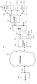
このために、この例では図2に示すような装置をもつONUレンジング遅延ユニット200をONU106が有する。特に、PSPONファイバ111とインターフェースをとるための、よく知られた型のPSPONインターフェース202を有するPSPON送信機201が示されている。PSPON111からの入力光信号は、光・電気(O/E)変換器203に供給されて、電気信号に変換される。
【0033】
その結果、その入力電気信号はコントローラ205に供給され、その中の入力インターフェース206に供給される。出力電気信号は、電気・光(E/O)変換器204によって光信号に変換される。その結果、その出力光信号はPSPONインターフェース202を介してPSPONファイバ111に供給される。
【0034】
コントローラ205は、中央処理装置(CPU)208(マイクロプロセッサでもよい)、メモリ209、ユーザ入出力(I/O)ユニット210、ステータスレジスタ211、割当タイムスロットレジスタ212、下流フレームのスタートレジスタ213、レンジング遅延レジスタ214、送信バースト・コントロールレジスタ215、及び、データ・ファーストイン・ファーストアウト(FIFO)レジスタ221を備えている。ユニット206、208乃至215、及び221は、バス207によって相互接続されている。
【0035】
ステータスレジスタ211からパワーオン・ステータス信号がANDゲート216の一方の入力に供給され、その間にステータスレジスタ211から初期化・ステータス信号がANDゲート216の禁止入力に供給される。したがって、ANDゲート216がハイ・ステート出力を発生するのは、パワーオン・ステータス信号がハイ状態で初期化・ステータス信号がロー状態のときである。ANDゲート216からのハイ・ステート出力は、ORゲートを介してレンジング・トーン発信機220に供給されて、所望のアウトバンド・レンジング・トーンの出力が供給できるようにする。
【0036】
この方法によりレンジング状態が得られる。なお、この例においては、アウトバンド・レンジング・トーンは466.56MHzで発生される。このレンジング・トーンは加算器222に供給され、その後、E/O204及びPSPONインターフェース202を介してPSPON111に供給される。
【0037】
検証状態信号がステータスレジスタ211からANDゲート218の一方の入力に供給され、その間に送信バースト制御信号が送信バースト・コントロール215からANDゲート218の他方の入力に供給される。ANDゲート218は、その供給された信号によってアウトバンド・レンジング・トーンを送信するように制御され、その間にタイムスロットが検証状態にされる。
【0038】
アクティブ状態信号はステータスレジスタ211からANDゲート219の1つの入力に供給され、送信バースト制御信号はANDゲート219の2番目の入力に供給され、クロック(CLK)信号はANDゲート219の3番目の入力に供給される。ANDゲート219は、その供給された信号によって制御され、CLK信号をデータFIFO221に供給し、それによりアクティブ状態が可能になる。データFIFO221からのデータ出力は、加算器222、E/O204、及びPSPONインターフェース202を介してPSPON111に供給される。
【0039】
ONUレンジング遅延ユニット200の動作は、後述する図4乃至図6のフローチャートに示す。
【0040】
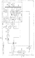
図3は、本発明の実施例に使用するOLCレンジング遅延ユニットの詳細なブロック図である。特に、PSPONファイバ110とインターフェースをとるための、よく知られた型のPSPONインターフェース302を有するPSPON送信機301が示されている。PSPON110からの入力光信号は、光・電気(O/E)変換器303に供給されて、電気信号に変換される。
【0041】
その結果、その入力電気信号は結合器306に供給され、インバンド(帯域内)・データ信号を抽出してコントローラ305に供給し、その中のI/O308に供給する。結合器306はまた、アウトバンド・レンジング・トーンを抽出して同調検出器307に供給する。アウトバンド・レンジング・トーンの受信を示す検出器307からのハイ状態出力は、ANDゲート316の1つ目の入力に供給される。
【0042】
コントローラ305に含まれているものは、I/O308、CPU310(マイクロプロセッサでもよい)、メモリ311、イネーブルレジスタ312、リセットレジスタ313、クロック314、及びレンジング遅延レジスタであり、これらはバス309によって相互接続されている。
【0043】
イネーブルレジスタ312からの出力は、ANDゲート316の2番目の入力に供給され、それがハイ状態信号であるときにハイ状態のトーン検出信号が出力され、ANDゲート316はイネーブル・ハイ状態信号をレンジング遅延タイマ317に供給する。これによりタイマ317はクロック314からのクロック出力をカウントすることが可能になる。
【0044】
上記したように、アウトバンド・レンジング・トーンがもう検出されないときは、タイマ317におけるカウント値は、このOLCに結合された固有のONUに対する折り返し遅延を提示している。その折り返し遅延期間は、レンジング遅延レジスタ315に供給される。リセットレジスタからのリセット信号は、レンジング遅延タイマ317を初期化する。
【0045】
OLCレンジング遅延ユニット300の動作は、後述する図7及び図8のフローチャートにおいて示す。
【0046】
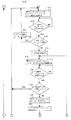
図4乃至図6において、A−A,B−B,C−C,D−D,E−E,及びF−Fで接続されるフローチャートは、図2のONUレンジング遅延ユニットのレンジング遅延手順におけるステップを示す。ONU106のレンジング遅延手順は、ステップ401から始まる。この後、ステップ402では、ONUがパワーオンであるか否かを判別する。その判別結果がNOである場合には、YESの結果が出るまでステップ402が繰り返される。
【0047】
次に、ステップ403では、ONUが初期化されているか否かを判別する。その判別結果がYESである場合には、ONU106は初期化状態になっており、制御はステップ408に移行する。ステップ403におけるその判別結果がNOである場合には、ONU106は初期化されてなくレンジング状態であり、ステップ404でアウトバンド・レンジング・トーンが送信される。
【0048】
なお、この例においては、レンジング・トーンは466.56MHzで発生されるが、それは通常のインバンドのメッセージ送信バンドの帯域外である。ステップ405では、ONU106によって受信されたのが放送メッセージであるか否かを判別する。その判別結果がNOである場合には、YESの結果が得られるまでステップ405が繰り返される。
【0049】
特に言及するのは、ONUがレンジング・トーンの送信を停止する命令を受信された放送メッセージが含んでいること、及び、ONUが1つのID(識別子)を持つことである。次に、ステップ406では、レンジング・トーンの送信を終了させる。ステップ407では、ONU106にIDを設定してONUIDとする。ステップ408では、ONUIDに対して決定するレンジング遅延に含まれるべき一義的な(unicast)メッセージが受信されたか否かを判別する。
【0050】
すなわち、フレームの番号である「F」、バイトの番号である「B」、及びビットの番号である「b」が受信されたか否かを判別する。この例では、Fは0、1、又は2の値であり、Bは0から2429までの値であり、bは0から7までの値である。ステップ409では、OUNIDに対するレンジング遅延に受信したF、B、及びbの値を設定する。ステップ410では、ONUIDに対する上りタイムスロット割当が受信されたか否かを判別する。
【0051】
その判別結果がNOである場合には、オフセット及びサイズによって自己識別される割当タイムスロットを有するYESの結果が出るまで、ステップ410が繰り返される。そのオフセットは各フレームの先頭からのバイト数であり、そのサイズはそのタイムスロット長のバイト数である。ステップ411は、このOUNIDに対して割当タイムスロットに含まれるべき一義的なメッセージが受信され、受信したオフセット及びサイズをその割当タイムスロットに設定することを示している。
【0052】
そして、このONUが検証状態になり、ステップ412では、割当タイムスロットのアウトバンド・トーンの送信を行う。次に、ステップ413では、このONUIDへの一義的なメッセージが受信されたか否かを判別する。その判別結果がNOである場合には、YESの結果が出るまでステップ413が繰り返される。ステップ414では、受信したメッセージがこのONUIDに対するレンジング遅延を含んでいるか否かを判別する。
【0053】
その判別結果がYESである場合には、ステップ415において、このONUIDに対するレンジング遅延に受信したF、B、及びbを設定する。特に言及するのは、検証状態においては、F、B、及びbに対する新たな値の受信を通して、レンジング遅延の値が良好に同調できることである。この後、ステップ414においてNOの結果が出るまで、ステップ412から415までが繰り返される。次に、ステップ416では、ONUをデータ状態に設定する。ステップ417では、割当タイムスロットにインバンド・データバーストを送信する。
【0054】
これによりONUはアクティブ状態になる。ステップ418では、このONUIDに対する一義的なメッセージが受信されたか否かを判別する。その判別結果がNOである場合には、YESの結果が出るまで、ステップ418がなんども繰り返される。次に、ステップ419では、受信した一義的なメッセージが検証状態への遷移であるか否かを判別する。その判別結果がYESである場合には、ONUは再び検証状態に入り、制御はステップ412に移行して、ステップ419においてNOの結果が出るまで、ステップ412からステップ419までが繰り返される。
【0055】
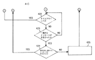
特に言及するのは、検証状態に再び入るのは、ONU106において何らかの特異な現象、例えば、停電又はOLC104からの制御メッセージが検出されたからである。次に、ステップ420では、割当タイムスロットにゼロ(0)を設定する。これによりONUはアイドル状態になる。ステップ421では、ONUにポーリングのためのステータス・タイマをセットする。
【0056】
この場合において、ステータス・タイマにおけるタイムアウト期間は「1」秒である。次に、ステップ422では、ステータス・タイマがタイムアウトしたか否かを判別する。その判別結果がYESである場合には、制御はステップ408に移行して、ステップ422においてNOの結果が出るまで、ステップ408から422までのうちの必要なステップが繰り返される。
【0057】
ステップ423では、このONUIDに対する一義的なメッセージが受信されたか否かを判別する。その判別結果がNOである場合には、これらのステップのいずれかの結果がYESになるまで、ステップ422及び423が繰り返される。ステップ422においてYESの結果が出た場合には上記した動作になる。ステップ423においてYESの結果が出た場合には、ステップ424において、検証状態に遷移する一義的なメッセージが受信されたか否かを判別する。
【0058】
その判別結果がYESである場合には、制御はステップ412に移行して、ステップ424においてNOの結果が出るまで、ステップ412から424までのうちの必要なステップが繰り返される。次に、ステップ425では、割当タイムスロットに新たな割当タイムスロット、すなわち、新たなオフセット及びサイズを設定する。この後、制御はステップ417に移行して、OUNが再びアクティブデータ状態すなわちその通常動作状態に入るまで、ステップ417から425までのうち相応のステップが繰り返される。
【0059】
このように、ポーリングされるONUがアウトバンド・レンジング・トーンに応答するということは、そのONUはすでに検証状態になっていて、結合しているOLCは、そのONUが以前から検証レンジングであったかのように取り扱うということを示している。アウトバンド・トーンが割当タイムスロットに適切に配置されるならば、そのONUはアクティブデータ状態に遷移される。
【0060】
さらに、ポーリングされるアイドルONUを要求することにより、アイドルONU、停電、及び下記に記述するOLCの動作に関連して再配置されるONUをシステム動作が識別できる。
【0061】
図7及び図8においてA−A及びB−Bで接続されるフローチャートは、図3のOLCレンジング遅延ユニットのレンジング遅延手順におけるステップを示す。OLCのレンジング遅延手順はステップ501から始まる。この後、ステップ502では、ONUIDからのレンジング・トーンがOLCによって受信されたか否かを判別する。
【0062】
その判別結果がNOである場合には、YESの結果が出るまでステップ502が繰り返される。次に、ステップ503では、ONUIDに対してメッセージが送信され、そのメッセージによりレンジング・トーンの送信が停止され、ONUのIDがONUIDとして割り当てられる。ステップ504では、レンジング遅延タイマがセットされる。
【0063】
次に、ステップ505では、レンジング・トーンの送信が停止したか否かを判別する。その判別結果がNOである場合には、YESの結果が出るまでステップ505が繰り返される。ステップ506では、レンジング遅延タイマが停止される。レンジング遅延タイマのタイム期間は、ONUIDに対するレンジング遅延である。
【0064】
すなわち、OLCによって送られるレンジング・トーンのメッセージの送信が終了してから、その終了が検出されるまでの期間が、ONUIDに対する折り返し遅延である。次に、ステップ507では、所定のレンジング遅延、すなわちF、B、及びbを有する一義的なメッセージがONUIDに送信される。ステップ508では、上りタイムスロットの割当、すなわちオフセット及びサイズを有するメッセージがONUIDに送信される。
【0065】
ステップ509では、現在受信しているアウトバンド・レンジング・遅延トーンが、割当タイムスロットに正しく位置合わせされているか否かを判別する。その判別結果がNOである場合には、ステップ510において、ONUIDのレンジング遅延を調整するためのメッセージをONUIDに対して送信する。この調整後に、再びステップ509において、アウトバンド・レンジング・トーンが割当タイムスロットに正しく位置合わせされているか否かを判別する。
【0066】
その判別結果がNOである場合には、ステップ509の結果がYESになるまで、ステップ510及び509が繰り返される。次に、ステップ511では、ONUがアクティブ状態に遷移することを示すメッセージをONUIDに対して送信する。ステップ512では、受信した上りデータがこのOLCに結合されるいずれかONUからのものであるか否かを判別する。
【0067】
判別結果がNOである場合には、YESの結果が出るまで、ステップ512が繰り返される。次に、ステップ513では、データを送信したONUIDに割り当てた正しいタイムスロットのデータであるか否かを判別する。その判別結果がYESである場合には、NOの結果が出るまで、ステップ513が繰り返される。ステップ514では、信号にロスがあるか否かを判別する。
【0068】
その判別結果がYESである場合には、ステップ515において検証状態に遷移するメッセージをONUIDに送信する。次に、制御はステップ508に移行して、ステップ515においてNOの結果が出るまで、ステップ508から515までのうち相応のステップが繰り返される。ステップ516では、大きなタイムスロット変動があるか否かを判別する。
【0069】
その判別結果がYESである場合には、制御はステップ515に移行して、ステップ516においてNOの結果が出るまで、ステップ508から516までのうち相応のステップが繰り返される。次に、ステップ517では、調整できない重大な問題があるか否かを判別する。その判別結果がYESである場合には、ステップ518においてONUIDに対して非初期化状態に入るべきメッセージを送信する。
【0070】
ステップ517において判別結果がNOである場合には、ステップ519においてタイムスロット変動が小さいものであるか否かを判別する。その判別結果がNOである場合には、制御はステップ512に移行して、ステップ519の結果がYESになるまで、ステップ512から519までのうち相応のステップが繰り返され、必要な場合には、ステップ508から519までのうち相応のステップが繰り返される。次に、ステップ520では、新たなレンジング遅延すなわち新たなF、B、及びbを有するメッセージがONUIDに対して送信される。
【0071】
特に言及するのは、停電によってOLCに結合している複数のONUが動作不能に陥ったならば、電源が回復したときに、自動回復システムがその複数のONUの動作の訂正状態を自動的に再確立しなければならない。電力を失う任意のPNUは、データの送信を停止して検証状態に逆戻りする。結合しているOLCは電力を失った複数のONUからの「ロス信号」を検出し、上りタイムスロット割当のリストからそれらを消去する。したがって上記したように、アクティブ状態でないONUのリストはポーリングされる。この結果、電源が回復したときに、それらのONUは一度にオンラインにもってこられる。
【0072】
任意のONUが移動された場合、あるいは切断された場合には、そのレンジング遅延をクリアすることによって、それは非初期化状態に置かれる。そのONUが再接続されたときは、上記したように、レンジング手順が初期化される。
【0073】
ある場合においては、ONUはシステム・オペレータに前もって知られることなく、切断されたり移動されることが可能である。例えば、ONUは切断された後、システム・オペレータに通知せずに、他のある位置に再接続されることが可能である。ONUが切断されたときは、上記したように、そのONUは電力を失って検証状態に遷移する。
【0074】
そのONUを再接続して再活動する試みがされたとしても、そのアウトバンド・レンジング・トーンは訂正されずに上りフレームに配置される。すなわち、そのアウトバンド・レンジング・トーンは不良なタイムスロットに配置されることになる。このことによって、結合されるOLCはメッセージを発生してそのONUに送るが、そのメッセージはそのONUを非初期化状態にリセットする。この結果、レンジング手順の自動的な活動に帰着する。すなわち、そのONUは新たに接続されたONUとして取り扱われる。
【0075】
このように、アウトバンド・レンジングは下り帯域幅の管理に影響を与えない。すなわち不可侵的である。さらに、「レンジング」衝突の可能性が最小になる。なぜならONUは通信網に接続されてパワーオンされたときには、直ちにレンジングするからである。さらにまた、上記したように、アウトバンド・レンジング・トーンは、不可侵的な検証、停電処理、低電力のスタンバイ状態への遷移、ONUの位置変更といった追加能力を提供する。
【0076】
上記した実施の形態はもちろん、本発明の原理を示したものに過ぎない。事実、非常に多くの他の方法や装置が、本発明の精神や範囲を逸脱することなく、当業者によって考案されるだろう。
【図面の簡単な説明】
【図1】 本発明の実施形態におけるビデオ分配システムの概略ブロック図。
【図2】 本発明の実施例に使用するONUレンジング遅延ユニットの詳細なブロック図。
【図3】 本発明の実施例に使用するOLCレンジング遅延ユニットの詳細なブロック図。
【図4】 図2のONUレンジング遅延ユニットのレンジング遅延手順におけるステップを示すフローチャートの図。
【図5】 図4のフローチャートとA−A及びB−Bで接続されるONUレンジング遅延ユニットのレンジング遅延手順におけるステップを示すフローチャートの図。
【図6】 図5のフローチャートとC−C,D−D,E−E,及びF−Fで接続されるONUレンジング遅延ユニットのレンジング遅延手順におけるステップを示すフローチャートの図。
【図7】 図3のOLCレンジング遅延ユニットのレンジング遅延手順におけるステップを示すフローチャートの図。
【図8】 図7のフローチャートとA−A及びB−Bで接続されるOLCレンジング遅延ユニットのレンジング遅延手順におけるステップを示すフローチャートの図。
【符号の説明】
100 通信網
101 ビデオサーバ
102 広帯域通信網
103 光伝送路端末
104 光伝送路回路
105 分離器
106 光通信網ユニット
107 テレビ受像機
108 リモート・コントロール・ユニット
109 伝送路
110 光ファイバ
111 光ファイバ
200 ONUレンジング遅延ユニット
201、301 PSPONトランシーバ
202、302 PSPONインターフェース
203、303 光・電気変換器
204、304 電気・光変換器
205、305 コントローラ
206 入力インターフェース
207、309 バス
208、310 CPU
209、311 メモリ
210 ユーザI/O
211 ステータスレジスタ
212 割当タイムスロットレジスタ
213 下りフレームスタートレジスタ
214、315 レンジング遅延レジスタ
215 送信バースト・コントロールレジスタ
216、218,219、316 ANDゲート
217 ORゲート
220 レンジングトーン発振器
221 データFIFO
222 加算器
300 OLCレンジング遅延ユニット
301 PSPONトランシーバ
302 PSPONインターフェース
306 結合器
307 同調検出器
308 入出力インターフェース
312 イネーブルレジスタ
313 リセットレジスタ
314 クロック
317 レンジング遅延ユニット[0001]
BACKGROUND OF THE INVENTION
The present invention relates to time division multiple access (TDMA) communications, and in particular, ranging in TDMA transmission. (Ranging) About.
[0002]
[Prior art]
[0003]
When transmitting signals in TDMA, it is necessary that all individual signal components of TDMA transmission have the same transmission delay. For this reason, a delay period must be determined for each signal included in the TDMA transmission, and when the delay period is added to each signal, the signal includes individual aliases in other signal components of the TDMA. A common aliasing delay equal to the delay occurs.
[0004]
To determine the inherent delay that is added to each signal component of the TDMA when any equipment unit that transmits the signal is deployed, relocated, or out of service, So-called" Ranging The procedure is executed. Well-known conventional general Ranging As a procedure, so-called "in-band (In-band) ・ Ranging There is. In-band Ranging The message is this in-band Ranging Used to execute
[0005]
However, this in-band Ranging To use a message, temporarily interrupt the transmission band and Ranging • A message needs to be transmitted. Therefore, in-band Ranging Is an intrusive procedure that interferes with normal bandwidth usage. In addition, in-band Ranging It is necessary to make a schedule when executing. In fact, in-band Ranging As the schedule ratio increases, the loss of transmission bandwidth also increases. This is extremely undesired. This is because this band cannot be used for other purposes, such as fixed-rate transmission purposes.
[0006]
[Problems to be solved by the invention]
The present invention provides such a conventional known in-band Ranging Problems and traditional in-band Ranging It is an object of the present invention to provide a TDMA communication apparatus, system, and communication method. The outline of the present invention is as follows.
[0007]
Inviolable outband (Out of band) ・ Ranging Use technology. Ranging Will automatically initialize the customer equipment unit when the equipment is placed, when the power supply is interrupted or temporarily restored, restored again, when the equipment is verified, after the equipment is disconnected. When reconnected or otherwise. For this purpose, out-of-band tones are used and when the customer equipment transmitting the TDMA signal is turned on, or transmitted in response to a specific command generated locally or remotely. The out-band tone is transmitted.
[0008]
In particular, Ranging When the customer equipment is out of band Ranging ・ Send a tone and send it from a remote terminal Ranging -Until a message expressing the end of tone transmission is received. The determined return delay is determined by sending the end message. Ranging A delay period until the end of the tone is detected. And the message sent to the customer device is Ranging ・ Includes a delay period and is used for all subsequent transmissions to the remote terminal.
[0009]
In one embodiment of the present invention, the customer equipment automatically transitions to the idle standby state when the remote terminal removes its upstream transmission slot. The customer equipment is still capable of receiving data even in a standby state and is periodically polled by a remote terminal that has assigned data to the upstream transmission slot. If the customer device in the standby state is not polled during a preset period, the customer device automatically transitions to the verification state.
[0010]
Further, when the customer device does not respond to polling, the remote terminal transmits a message including the fact to the customer device in the verification state. If the polled customer device expresses that it is in a verification state in response to an out-of-band tone, the remote terminal is verifying that customer device. Ranging Treat as If the outband tone is properly matched, the customer equipment is transitioned to the active state.
[0011]
An advantage of polling customer equipment in idle standby is that system operation can identify idle customer equipment, power outages, disconnected or removed customer equipment.
[0012]
[Means for Solving the Problems]
The present invention is an apparatus for use in at least one local equipment unit to obtain a signal propagation delay period between at least one local equipment unit and a remote equipment unit at a defined remote location,
a) an indicator for supplying an indication as to whether or not the power of the local device unit is on;
b) Ranging An indicator responsive to a power on indication to indicate whether at least one local equipment unit has been initialized by establishing a delay period;
c) in a frequency band other than the frequency band in which a data signal is transmitted from the at least one local device unit to the remote device unit in response to an indication that the at least one local device unit has not been initialized. Out-band Ranging A controllable transmitter that transmits delay and tone;
d) the out-band Ranging Out of band from the remote device unit controlling the controllable transmitter to finish sending delay, tone, message Ranging A receiver for receiving a delay-tone-message transmission stop and receiving a message having a representation of a delay period applied to an in-band data signal transmitted from the at least one local equipment unit to the remote equipment unit; ,
A TDMA communication apparatus is provided.
[0013]
The present invention is an apparatus for use in a remote equipment unit at a remote location defined to generate a signal propagation delay period between the remote equipment unit and at least one local equipment unit at the local location comprising:
a) Out-band Ranging A detector for detecting delay and tone reception;
b) said Ranging In response to detection of delay / tone reception, Ranging Send an end message to the at least one local equipment unit to end the transmission of the delay / tone, and to the at least one local equipment unit; Ranging A transmitter for transmitting a message having a representation of a delay period;
c) start when the end message is sent and Ranging Stop when the detector detects that the end of delay / tone has been received, and set the period from the start to the stop. Ranging A delay timer for the delay period;
A TDMA communication apparatus is provided.
[0014]
The present invention is an apparatus for use in at least one local equipment unit to obtain a signal propagation delay period between at least one local equipment unit and a remote equipment unit at a defined remote location,
a) means for providing an indication as to whether the power of the local equipment unit is on;
b) Ranging Means for responding to the power on indication to indicate whether at least one local equipment unit has been initialized by establishing a delay period;
c) in a frequency band other than the frequency band in which a data signal is transmitted from the at least one local device unit to the remote device unit in response to an indication that the at least one local device unit has not been initialized. Out-band Ranging Means for transmitting delay and tone;
d) the out-band Ranging Out of band from the remote device unit controlling the controllable transmitter to finish sending delay, tone, message Ranging Means for receiving a delay tone message transmission stop and receiving a message having a representation of a delay period applied to an in-band data signal transmitted from the at least one local device unit to the remote device unit;
A TDMA communication apparatus is provided.
[0015]
The present invention is an apparatus for use in a remote equipment unit at a remote location defined to generate a signal propagation delay period between the remote equipment unit and at least one local equipment unit at the local location comprising:
a) Out-band Ranging Means for detecting delay and tone reception;
b) said Ranging In response to detection of delay / tone reception, Ranging Send an end message to the at least one local equipment unit to end the transmission of the delay / tone, and to the at least one local equipment unit; Ranging Means for sending a message having a representation of a delay period;
c) start when the end message is sent and Ranging Stop when the detector detects that the end of delay / tone has been received, and set the period from the start to the stop. Ranging A delay timer for the delay period;
A TDMA communication apparatus is provided.
[0016]
The present invention is an apparatus for use in a system having at least one local equipment unit and a remote equipment unit to obtain a signal propagation delay period between at least one local equipment unit and a remote equipment unit,
For use in the at least one local equipment unit;
a) an indicator for supplying an indication as to whether or not the power of the local device unit is on;
b) Ranging An indicator responsive to a power on indication to indicate whether at least one local equipment unit has been initialized by establishing a delay period;
c) in a frequency band other than the frequency band in which a data signal is transmitted from the at least one local device unit to the remote device unit in response to an indication that the at least one local device unit has not been initialized. Out-band Ranging A controllable transmitter that transmits delay and tone;
d) the out-band Ranging Out of band from the remote device unit controlling the controllable transmitter to finish sending delay, tone, message Ranging A local receiver that receives a delay, tone, message suspension and receives a message having a representation of a delay period applied to an in-band data signal transmitted from the at least one local equipment unit to the remote equipment unit When,
For use in the remote device unit,
e) Out-band Ranging A detector for detecting delay and tone reception;
f) said Ranging In response to detection of delay / tone reception, Ranging Send an end message to the at least one local equipment unit to end the transmission of the delay / tone, and to the at least one local equipment unit; Ranging A local transmitter for sending a message having a representation of a delay period;
g) start when the end message is sent and Ranging Stop when the detector detects that the end of delay / tone has been received, and set the period from the start to the stop. Ranging A delay timer for the delay period;
A TDMA communication apparatus is provided.
[0017]
The present invention is a method for use in at least one local equipment unit to obtain a signal propagation delay period between at least one local equipment unit and a remote equipment unit at a defined remote location comprising:
a) providing an indication of whether the local equipment unit is powered on;
b) Ranging Responding to the power on indication to indicate whether at least one local equipment unit has been initialized by establishing a delay period;
c) in a frequency band other than the frequency band in which a data signal is transmitted from the at least one local device unit to the remote device unit in response to an indication that the at least one local device unit has not been initialized. Out-band Ranging Controllable steps to send delay and tone,
d) the out-band Ranging Out of band from the remote device unit controlling the controllable transmitter to finish sending delay, tone, message Ranging Receiving a delay-tone message transmission stop and receiving a message having a representation of a delay period applied to an in-band data signal transmitted from the at least one local equipment unit to the remote equipment unit;
A TDMA communication method comprising:
[0018]
The present invention is a method for use in a remote equipment unit at a remote location defined to generate a signal propagation delay period between the remote equipment unit and at least one local equipment unit at the local location comprising:
a) Out-band Ranging Detecting delay / tone reception;
b) said Ranging In response to detection of delay / tone reception, Ranging Send an end message to the at least one local equipment unit to end the transmission of the delay / tone, and to the at least one local equipment unit; Ranging Sending a message having a representation of a delay period;
c) start when the end message is sent and Ranging Stop when the detector detects that the end of delay / tone has been received, and set the period from the start to the stop. Ranging Controlling a delay timer as a delay period;
A TDMA communication method comprising:
[0019]
The present invention is a method for use in a system having at least one local equipment unit and a remote equipment unit to obtain a signal propagation delay period between at least one local equipment unit and a remote equipment unit, comprising:
For use in the at least one local equipment unit;
a) providing an indication of whether the local equipment unit is powered on;
b) Ranging Responding to the power on indication to indicate whether at least one local equipment unit has been initialized by establishing a delay period;
c) in a frequency band other than the frequency band in which a data signal is transmitted from the at least one local device unit to the remote device unit in response to an indication that the at least one local device unit has not been initialized. Out-band Ranging Controllable steps to send delay and tone,
d) the out-band Ranging Out of band from the remote device unit controlling the controllable transmitter to finish sending delay, tone, message Ranging Receiving a delay tones message transmission stop and receiving a message having a representation of a delay period applied to an in-band data signal transmitted from the at least one local equipment unit to the remote equipment unit;
For use in the remote device unit,
e) Out-band Ranging Detecting delay / tone reception;
f) said Ranging In response to detection of delay / tone reception, Ranging Send an end message to the at least one local equipment unit to end the transmission of the delay / tone, and to the at least one local equipment unit; Ranging A local step of sending a message having a representation of a delay period;
g) start when the end message is sent and Ranging Stop when the detector detects that the end of delay / tone has been received, and set the period from the start to the stop. Ranging Controlling a delay timer as a delay period;
A TDMA communication method comprising:
[0020]
DETAILED DESCRIPTION OF THE INVENTION
FIG. 1 is a schematic block diagram of a video distribution system in an embodiment of the present invention. In particular, the illustrated
[0021]
In the optical transmission line terminal (OLT) 103, the optical transmission line circuit (OLC) 104 serves as an interface to the optical fiber transmission line. The optical fiber transmission line is, for example, a power division passive optical communication network (PSPON), and includes
[0022]
The
[0023]
In this example, downstream video signals are transmitted in asynchronous mode (ATM) cells with time division multiplexing (TDM), while upstream communication is transmitted with time division multiple access (TDMA). Further, the communication speed to the downstream and upstream is 155.52 Mb / sec. In order to enable upstream TDMA communication, it is necessary that all of the multiple optical network units (ONUs) have equal folding delays for the combined OLC 104.
[0024]
this is Ranging This is realized by using a procedure. Ranging The procedure is performed when each
[0025]
In fact, the
[0026]
Therefore, the uplink channel selection message sent to the video service controller in the
[0027]
In addition, messages sent by the
[0028]
The optical communication network unit (ONU) 106 terminates the PSPON 111 fiber, and in this example, can provide an appropriate interface to a plurality of television receivers (TVs) 107-1 to 107-N. Each of the TVs 107-1 to 107-N includes an attached remote control (RC) unit 108-1 to 108-N, respectively.
[0029]
In this example, the
[0030]
As shown in FIG. 1, the residential video subsystem includes one
[0031]
As mentioned above, the desired Ranging The delay is introduced by obtaining a measure of the wraparound delay between the
[0032]
For this reason, in this example, an ONU having a device as shown in FIG. Ranging The
[0033]
As a result, the input electric signal is supplied to the
[0034]
The
[0035]
A power-on status signal is supplied from the
[0036]
This way Ranging A state is obtained. In this example, out-of-band Ranging Tones are generated at 466.56 MHz. this Ranging The tone is supplied to the
[0037]
A verification status signal is provided from the
[0038]
The active state signal is supplied from the
[0039]
ONU Ranging The operation of the
[0040]
FIG. 3 shows the OLC used in the embodiment of the present invention. Ranging It is a detailed block diagram of a delay unit. In particular, a
[0041]
As a result, the input electrical signal is supplied to the
[0042]
The
[0043]
The output from the enable
[0044]
As mentioned above, Ranging When the tone is no longer detected, the count value in
[0045]
OLC Ranging The operation of the
[0046]
4 to 6, the flowcharts connected by AA, BB, CC, DD, EE, and FF are shown in FIG. Ranging Delay unit Ranging The steps in the delay procedure are shown. ONU106 Ranging The delay procedure begins at
[0047]
Next, in
[0048]
In this example, Ranging A tone is generated at 466.56 MHz, which is out of the normal in-band message transmission band. In
[0049]
Of particular mention is that ONU Ranging The received broadcast message includes a command to stop tone transmission, and the ONU has one ID (identifier). Next, in
[0050]
That is, it is determined whether or not the frame number “F”, the byte number “B”, and the bit number “b” are received. In this example, F is a value of 0, 1, or 2, B is a value from 0 to 2429, and b is a value from 0 to 7. In
[0051]
If the determination result is NO,
[0052]
Then, the ONU enters a verification state, and in
[0053]
If the determination result is YES, in
[0054]
As a result, the ONU enters an active state. In
[0055]
In particular, the verification state is re-entered because some unusual phenomenon has been detected in the
[0056]
In this case, the timeout period in the status timer is “1” seconds. Next, in
[0057]
In
[0058]
If the determination result is YES, the control proceeds to step 412 and necessary steps of
[0059]
In this way, the polled ONU is out-of-band Ranging ・ To respond to a tone, the ONU has already been verified, and the associated OLC has previously verified the ONU. Ranging It shows that it is handled as if it were. If the outband tone is properly placed in the assigned time slot, the ONU is transitioned to the active data state.
[0060]
Further, by requesting polled idle ONUs, system operation can identify idle ONUs, power outages, and ONUs that are relocated in relation to the OLC operations described below.
[0061]
7 and FIG. 8, the flowcharts connected by AA and BB are shown in FIG. Ranging Delay unit Ranging The steps in the delay procedure are shown. OLC Ranging The delay procedure begins at
[0062]
If the determination result is NO,
[0063]
Next, in
[0064]
Ie sent by OLC Ranging The period from the end of transmission of the tone message until the end of the message is detected is the return delay for the ONUID. Next, in
[0065]
In
[0066]
If the determination result is NO, steps 510 and 509 are repeated until the result of
[0067]
If the determination result is NO,
[0068]
If the determination result is YES, in
[0069]
If the determination result is YES, the control proceeds to step 515, and corresponding steps of
[0070]
If the determination result in
[0071]
In particular, if multiple ONUs that are coupled to the OLC have become inoperable due to a power outage, when the power is restored, the automatic recovery system automatically sets the corrected status of the multiple ONUs to operate. Must be re-established. Any PNU that loses power stops sending data and reverts to the verification state. The combined OLC detects “loss signals” from multiple ONUs that have lost power and removes them from the list of uplink time slot assignments. Therefore, as described above, the list of ONUs that are not active is polled. As a result, when power is restored, those ONUs are brought online at once.
[0072]
If any ONU is moved or disconnected, its Ranging By clearing the delay, it is put in an uninitialized state. When the ONU is reconnected, as described above, Ranging The procedure is initialized.
[0073]
In some cases, the ONU can be disconnected or moved without prior knowledge of the system operator. For example, an ONU can be disconnected and then reconnected to some other location without notifying the system operator. When the ONU is disconnected, as described above, the ONU loses power and transits to the verification state.
[0074]
Even if there is an attempt to reconnect and reactivate the ONU, Ranging The tone is placed in the upstream frame without correction. That is, its out-band Ranging • Tones will be placed in bad time slots. This causes the combined OLC to generate a message and send it to the ONU, which resets the ONU to an uninitialized state. As a result, Ranging Resulting in automatic activity of the procedure. That is, the ONU is treated as a newly connected ONU.
[0075]
In this way, out-of-band Ranging Does not affect downstream bandwidth management. In other words, it is inviolable. further," Ranging "The possibility of collision is minimized. Because when the ONU is connected to the communication network and powered on, Ranging Because it does. Furthermore, as mentioned above, Ranging Tones provide additional capabilities such as intrusive verification, power failure handling, transition to a low power standby state, and ONU repositioning.
[0076]
Of course, the above-described embodiments are merely illustrative of the principles of the present invention. Indeed, numerous other methods and devices will be devised by those skilled in the art without departing from the spirit and scope of the invention.
[Brief description of the drawings]
FIG. 1 is a schematic block diagram of a video distribution system in an embodiment of the present invention.
FIG. 2 shows an ONU used in an embodiment of the present invention. Ranging The detailed block diagram of a delay unit.
FIG. 3 shows an OLC used in an embodiment of the present invention. Ranging The detailed block diagram of a delay unit.
4 is an ONU in FIG. Ranging Delay unit Ranging The figure of the flowchart which shows the step in a delay procedure.
5 is a flowchart of FIG. 4 and ONUs connected by AA and BB. Ranging Delay unit Ranging The figure of the flowchart which shows the step in a delay procedure.
6 is an ONU connected by the flowchart of FIG. 5 and CC, DD, EE, and FF. Ranging Delay unit Ranging The figure of the flowchart which shows the step in a delay procedure.
FIG. 7 shows the OLC of FIG. Ranging Delay unit Ranging The figure of the flowchart which shows the step in a delay procedure.
FIG. 8 is a flowchart of FIG. 7 and an OLC connected by AA and BB. Ranging Delay unit Ranging The figure of the flowchart which shows the step in a delay procedure.
[Explanation of symbols]
100 communication network
101 Video server
102 Broadband communication network
103 Optical transmission line terminal
104 Optical transmission line circuit
105 Separator
106 Optical communication network unit
107 TV receiver
108 Remote control unit
109 Transmission line
110 optical fiber
111 optical fiber
200 ONU Ranging Delay unit
201, 301 PSPON transceiver
202, 302 PSPON interface
203, 303 Photoelectric converter
204, 304 Electrical / optical converter
205, 305 controller
206 Input interface
207, 309 bus
208, 310 CPU
209, 311 memory
210 User I / O
211 Status register
212 Allocation time slot register
213 Downstream frame start register
214, 315 Ranging Delay register
215 Transmit burst control register
216, 218, 219, 316 AND gate
217 OR gate
220 Ranging Tone oscillator
221 data FIFO
222 Adder
300 OLC Ranging Delay unit
301 PSPON transceiver
302 PSPON interface
306 coupler
307 Tuning detector
308 I / O interface
312 Enable register
313 Reset register
314 clock
317 Ranging Delay unit
Claims (77)
a)前記ローカル機器ユニットの電源がオンであるか否かの指示を供給する指示器と、
b)電源がオンであることの指示に応答して、レンジング遅延期間を確立することにより前記少なくとも1つのローカル機器ユニットが初期化されているか否かを示す指示器と、
c)前記少なくとも1つのローカル機器ユニットが初期化されていないことの指示に応答して、前記少なくとも1つのローカル機器ユニットから前記リモート機器ユニットに対してデータ信号が送信される周波数帯域以外の周波数帯域において帯域外レンジング遅延・トーンを送信する制御可能な送信機と、
d)前記帯域外レンジング遅延・トーン・メッセージの送信を終了するように前記制御可能な送信機を制御する前記リモート機器ユニットから帯域外レンジング遅延・トーン・メッセージの送信停止を受信し、前記少なくとも1つのローカル機器ユニットから前記リモート機器ユニットに送信される帯域内データ信号に適用される遅延期間の表示を有するメッセージを受信する受信機と、
からなる装置。An apparatus for use in the at least one local equipment unit at a predetermined local location to obtain a signal propagation ranging delay period between the at least one local equipment unit and the remote equipment unit at the predetermined remote location,
a) an instruction for supplying an indication of whether the or the power of the local equipment unit is on,
In response to an instruction that b) the power is on, and indicates to the finger示器whether the at least one local equipment unit has been initialized by establishing a ranging delay period,
c) in response to the indication that the at least one local equipment unit has not been initialized, at least one of the frequency band other than the data signal is transmitted from the local equipment unit to the remote equipment unit A controllable transmitter for transmitting out- of- band ranging delay and tone at
d) receiving the transmission stop of the band ranging delay tone message the remote equipment unit band ranging delay tone message from controlling said controllable transmitter to terminate transmission of said at least A receiver for receiving a message having an indication of a delay period applied to an in- band data signal transmitted from one local equipment unit to the remote equipment unit;
Tona Ru equipment.
a)帯域外レンジング遅延・トーンの受信を検出する検出器と、
b)前記レンジング遅延・トーンの受信の検出に応答して、前記レンジング遅延・トーンの送信を終了するために前記少なくとも1つのローカル機器ユニットに対して終了メッセージを送信し、前記少なくとも1つのローカル機器ユニットに対してレンジング遅延期間の表示を含むメッセージを送信する送信機と、
c)前記終了メッセージを送信したときに開始し前記レンジング遅延・トーンの終了を受信したことを前記検出器が検出したときに停止し、前記開始から前記停止までの期間を前記レンジング遅延期間とする遅延タイマと、
からなる装置。An apparatus for use in a remote equipment unit at a predetermined remote location to generate a signal propagation ranging delay period between the remote equipment unit and at least one local equipment unit at the local location, comprising:
a) a detector to detect reception of out-of-band ranging delay and tones;
b) in response to the detection of the reception of the ranging delay tone, it said sending a termination message to at least one local equipment unit to terminate the transmission of the ranging delay tone, the at least one local device A transmitter for sending a message including an indication of the ranging delay period to the unit;
c) Start when the end message is transmitted, stop when the detector detects that the end of the ranging delay / tone is received, and set the period from the start to the stop as the ranging delay period A delay timer;
Tona Ru equipment.
a)前記少なくとも1つのローカル機器ユニットの電源がオンであるか否かの指示を供給する手段と、
b)電源がオンであるという指示に応答して、レンジング遅延期間を確立することにより前記少なくとも1つのローカル機器ユニットが初期化されているか否かを示す手段と、
c)少なくとも1つのローカル機器ユニットが初期化されていないことの指示に応答して、前記少なくとも1つのローカル機器ユニットから前記リモート機器ユニットに対してデータ信号が送信される周波数帯域以外の周波数帯域において帯域外レンジング遅延・トーンを送信する手段と、
d)前記帯域外レンジング遅延・トーン・メッセージの送信を終了するように制御可能な送信機を制御するために前記リモート機器ユニットから帯域外レンジング遅延・トーン・メッセージの送信停止を受信し、前記少なくとも1つのローカル機器ユニットから前記リモート機器ユニットに送信される帯域内データ信号に適用される遅延期間の表示を含むメッセージを受信する手段と、
からなる装置。An apparatus for use in at least one local equipment unit at a predetermined local location to obtain a signal propagation ranging delay period between the at least one local equipment unit and the remote equipment unit at the predetermined remote location,
a) means for providing an indication as to whether the at least one local device unit is powered on;
b) in response to an indication that the power is on, and the at least one whether the shown to hand stage local equipment unit has been initialized by establishing a ranging delay period,
c) in a frequency band other than the frequency band in which a data signal is transmitted from the at least one local device unit to the remote device unit in response to an indication that the at least one local device unit has not been initialized. Means for transmitting out-of-band ranging delay and tone;
d) receiving the transmission stop of the band ranging delay tone message from the remote equipment unit for controlling the controllable transmitter to terminate transmission of the out-of-band ranging delay tone message, at least Means for receiving a message including an indication of a delay period applied to an in- band data signal transmitted from one local equipment unit to the remote equipment unit;
Tona Ru equipment.
a)帯域外レンジング遅延・トーンの受信を検出する手段と、
b)前記レンジング遅延・トーンの受信の検出に応答して、前記レンジング遅延・トーンの送信を終了するために前記少なくとも1つのローカル機器ユニットに対して終了メッセージを送信し、前記少なくとも1つのローカル機器ユニットに対してレンジング遅延期間の表示を有するメッセージを送信する手段と、
c)前記終了メッセージを送信したときに開始し前記レンジング遅延・トーンの終了を受信したことを前記検出器が検出したときに停止し、前記開始から前記停止までの期間を前記レンジング遅延期間とする遅延タイマと、
からなる装置。An apparatus for use in a remote equipment unit at a predetermined remote location to generate a signal propagation ranging delay period between the remote equipment unit and at least one local equipment unit at the local location, comprising:
a) means for detecting reception of out-of-band ranging delay and tone;
b) in response to the detection of the reception of the ranging delay tone, it said sending a termination message to at least one local equipment unit to terminate the transmission of the ranging delay tone, the at least one local device Means for sending a message with an indication of the ranging delay period to the unit;
c) Start when the end message is transmitted, stop when the detector detects that the end of the ranging delay / tone is received, and set the period from the start to the stop as the ranging delay period A delay timer;
Tona Ru equipment.
前記少なくとも1つのローカル機器ユニットにおいて使用するための、
a)前記少なくとも1つのローカル機器ユニットの電源がオンであるか否かの指示を供給する指示器と、
b)電源がオンであるという指示に応答して、レンジング遅延期間を確立することにより前記少なくとも1つのローカル機器ユニットが初期化されているか否かを示す指示器と、
c)前記少なくとも1つのローカル機器ユニットが初期化されていないことの指示に応答して、前記少なくとも1つのローカル機器ユニットから前記リモート機器ユニットに対してデータ信号が送信される周波数帯域以外の周波数帯域において帯域外レンジング遅延・トーンを送信する制御可能な送信機と、
d)制御可能な送信機を前記帯域外レンジング遅延・トーン・メッセージの送信を終了するように制御するために前記リモート機器ユニットから帯域外レンジング遅延・トーン・メッセージの送信停止を受信し、前記少なくとも1つのローカル機器ユニットから前記リモート機器ユニットに送信される帯域内データ信号に適用される遅延期間の表示を有するメッセージを受信するローカル受信機と、
前記リモート機器ユニットに使用するための、
e)帯域外レンジング遅延・トーンの受信を検出する検出器と、
f)前記レンジング遅延・トーンの受信の検出に応答して、前記レンジング遅延・トーンの送信を終了するために前記少なくとも1つのローカル機器ユニットに対して終了メッセージを送信し、前記少なくとも1つのローカル機器ユニットに対してレンジング遅延期間の表示を有するメッセージを送信するリモート送信機と、
g)前記終了メッセージを送信したときに開始し前記レンジング遅延・トーンの終了を受信したことを前記検出器が検出したときに停止し、前記開始から前記停止までの期間を前記レンジング遅延期間とする遅延タイマと、
からなる装置。An apparatus for use in a system having at least one local equipment unit and a remote equipment unit to obtain a signal propagation ranging delay period between at least one local equipment unit and a remote equipment unit, comprising:
For use in the at least one local equipment unit;
a) an indicator for providing an indication as to whether the at least one local device unit is powered on;
b) power supply in response to the indication that is on, and indicates to the finger示器whether the at least one local equipment unit has been initialized by establishing a ranging delay period,
c) in response to the indication that the at least one local equipment unit has not been initialized, at least one of the frequency band other than the data signal is transmitted from the local equipment unit to the remote equipment unit A controllable transmitter for transmitting out- of- band ranging delay and tone at
d) a controllable transmitter receives the transmission stop of the band ranging delay tone message from said remote equipment unit to control so as to terminate the transmission of the out-of-band ranging delay tone message, the A local receiver for receiving a message having an indication of a delay period applied to an in- band data signal transmitted from at least one local equipment unit to the remote equipment unit;
For use in the remote device unit,
e) a detector to detect reception of out-of-band ranging delay and tones;
f) in response to the detection of the reception of the ranging delay tone, it said sending a termination message to at least one local equipment unit to terminate the transmission of the ranging delay tone, the at least one local device A remote transmitter that sends a message with an indication of the ranging delay period to the unit;
g) Start when the end message is transmitted and stop when the detector detects that the ranging delay / tone end has been received, and the period from the start to the stop is the ranging delay period A delay timer;
Tona Ru equipment.
a)前記少なくとも1つのローカル機器ユニットの電源がオンであるか否かの指示を供給するステップと、
b)電源がオンであるとの指示に応答して、レンジング遅延期間を確立することにより、前記少なくとも1つのローカル機器ユニットが初期化されているか否かを示すステップと、
c)前記少なくとも1つのローカル機器ユニットが初期化されていないことの指示に応答して、前記少なくとも1つのローカル機器ユニットから前記リモート機器ユニットに対してデータ信号が送信される周波数帯域以外の周波数帯域において帯域外レンジング遅延・トーンを送信するステップと、
d)前記帯域外レンジング遅延・トーンの送信を終了するように制御可能な送信機を制御するために、前記リモート機器ユニットから帯域外レンジング遅延・トーン・メッセージの送信停止を受信し、前記少なくとも1つのローカル機器ユニットから前記リモート機器ユニットに送信される帯域内データ信号に適用される遅延期間の表示を有するメッセージを受信するステップと、
からなる方法。A method for use in the at least one local equipment unit at a predetermined local location to obtain a signal propagation ranging delay period between the at least one local equipment unit and the remote equipment unit at the predetermined remote location , comprising :
a) providing an indication of whether the at least one local device unit is powered on;
b) power supply in response to an instruction to be turned on, by establishing the ranging delay period, said at least one whether the indicate to step the local equipment unit has been initialized,
c) in response to the indication that the at least one local equipment unit has not been initialized, at least one of the frequency band other than the data signal is transmitted from the local equipment unit to the remote equipment unit and Luz step to send an out-of-band ranging delay tone in,
d) in order to control the controllable transmitter to terminate transmission of the out-of-band ranging delay-tone, receives the transmission stop of the band ranging delay tone message from said remote equipment unit, at least Receiving a message having an indication of a delay period applied to an in- band data signal transmitted from one local equipment unit to the remote equipment unit;
Tona Ru way.
a)帯域外レンジング遅延・トーンの受信を検出するステップと、
b)前記レンジング遅延・トーンの受信の検出に応答して、前記レンジング遅延・トーンの送信を終了するために前記少なくとも1つのローカル機器ユニットに対して終了メッセージを送信し、前記少なくとも1つのローカル機器ユニットに対してレンジング遅延期間の表示を有するメッセージを送信するステップと、
c)前記終了メッセージを送信したときに開始し前記レンジング遅延・トーンの終了を受信したことを前記検出器が検出したときに停止し、前記開始から前記停止までの期間を前記レンジング遅延期間とするように、遅延タイマを制御するステップと、
からなる方法。A method for use in a remote equipment unit at a predetermined remote location to generate a signal propagation ranging delay period between the remote equipment unit and at least one local equipment unit at the local location, comprising:
a) detecting reception of out-of-band ranging delay / tone;
b) in response to the detection of the reception of the ranging delay tone, it said sending a termination message to at least one local equipment unit to terminate the transmission of the ranging delay tone, the at least one local device Sending a message with an indication of the ranging delay period to the unit;
c) Start when the end message is transmitted, stop when the detector detects that the end of the ranging delay / tone is received, and set the period from the start to the stop as the ranging delay period as such, the step of controlling the delay timer,
Tona Ru way.
前記少なくとも1つのローカル機器ユニットにおいて使用するための、
a)前記少なくとも1つのローカル機器ユニットの電源がオンであるか否かの指示を供給するステップと、
b)電源がオンであるとの指示に応答して、レンジング遅延期間を確立することにより前記少なくとも1つのローカル機器ユニットが初期化されているか否かを示すステップと、
c)前記少なくとも1つのローカル機器ユニットが初期化されていないことの指示に応答して、前記少なくとも1つのローカル機器ユニットから前記リモート機器ユニットに対してデータ信号が送信される周波数帯域以外の周波数帯域において帯域外レンジング遅延・トーンを送信するステップと、
d)前記帯域外レンジング遅延・トーン・メッセージの送信を終了するように制御可能な送信機を制御するために、前記リモート機器ユニットから帯域外レンジング遅延・トーン・メッセージの送信停止を受信し、前記少なくとも1つのローカル機器ユニットから前記リモート機器ユニットに送信される帯域内データ信号に適用される遅延期間の表示を有するメッセージを受信するステップと、
前記リモート機器ユニットに使用するための、
e)帯域外レンジング遅延・トーンの受信を検出するステップと、
f)前記少なくとも1つのローカル機器ユニットからの前記レンジング遅延・トーンの受信の検出に応答して、前記レンジング遅延・トーンの送信を終了するために前記少なくとも1つのローカル機器ユニットに対して終了メッセージを送信するステップと、
g)前記少なくとも1つのローカル機器ユニットに対してレンジング遅延期間の表示を有するメッセージを送信するステップと、
h)前記終了メッセージを送信したときに開始し前記レンジング遅延・トーンの終了を受信したことを前記検出器が検出したときに停止し、前記開始から前記停止までの期間を前記レンジング遅延期間とするように、遅延タイマを制御するステップと、
からなる方法。A method of Oite used in a system having at least one local equipment unit and the remote device unit to obtain a signal propagation ranging delay period between the at least one local equipment unit and the remote equipment unit,
For use in the at least one local equipment unit;
a) providing an indication of whether the at least one local device unit is powered on;
b) power supply in response to an instruction to be turned on, and indicate to step whether the at least one local equipment unit has been initialized by establishing a ranging delay period,
c) in response to the indication that the at least one local equipment unit has not been initialized, at least one of the frequency band other than the data signal is transmitted from the local equipment unit to the remote equipment unit and Luz step to send an out-of-band ranging delay tone in,
d) in order to control the controllable transmitter to terminate transmission of the out-of-band ranging delay tone message, it receives the transmission stop of the band ranging delay tone message from said remote equipment unit, wherein Receiving a message having an indication of a delay period applied to an in- band data signal transmitted from at least one local equipment unit to the remote equipment unit;
For use in the remote device unit,
e) detecting reception of out-of-band ranging delay / tone;
f) in response to the detection of the reception of the ranging delay tone from said at least one local equipment unit, a termination message to the at least one local equipment unit to terminate the transmission of the ranging delay tone and transmitting,
and Luz steps to send a message with an indication of the ranging delay period relative to g) at least one local equipment unit,
h ) Start when the end message is transmitted and stop when the detector detects that the end of the ranging delay / tone is received, and the period from the start to the stop is the ranging delay period as such, the step of controlling the delay timer,
Tona Ru way.
Applications Claiming Priority (2)
| Application Number | Priority Date | Filing Date | Title |
|---|---|---|---|
| US09/356,980 US6807188B1 (en) | 1999-07-19 | 1999-07-19 | Ranging arrangement and method for TDMA communications |
| US09/356980 | 1999-07-19 |
Publications (3)
| Publication Number | Publication Date |
|---|---|
| JP2001069102A JP2001069102A (en) | 2001-03-16 |
| JP2001069102A5 JP2001069102A5 (en) | 2009-01-08 |
| JP4652532B2 true JP4652532B2 (en) | 2011-03-16 |
Family
ID=23403793
Family Applications (1)
| Application Number | Title | Priority Date | Filing Date |
|---|---|---|---|
| JP2000217060A Expired - Fee Related JP4652532B2 (en) | 1999-07-19 | 2000-07-18 | TDMA communication apparatus and communication method thereof |
Country Status (2)
| Country | Link |
|---|---|
| US (2) | US6807188B1 (en) |
| JP (1) | JP4652532B2 (en) |
Families Citing this family (30)
| Publication number | Priority date | Publication date | Assignee | Title |
|---|---|---|---|---|
| US6807188B1 (en) * | 1999-07-19 | 2004-10-19 | Lucent Technologies Inc. | Ranging arrangement and method for TDMA communications |
| US20060072520A1 (en) * | 2000-03-23 | 2006-04-06 | Chitrapu Prabhakar R | Time synchronized standby state to the GPRS medium access control protocol with applications to mobile satellite systems |
| WO2003001737A2 (en) * | 2000-10-26 | 2003-01-03 | Wave7 Optics, Inc. | Method and system for processing upstream packets of an optical network |
| EP1271825A1 (en) * | 2001-06-25 | 2003-01-02 | Lucent Technologies Inc. | Method and system for multiplexed optical information transport |
| WO2003005611A2 (en) | 2001-07-05 | 2003-01-16 | Wave7 Optics, Inc. | System and method for communicating optical signals to multiple subscribers having various bandwidth demands connected to the same optical waveguide |
| US7877014B2 (en) | 2001-07-05 | 2011-01-25 | Enablence Technologies Inc. | Method and system for providing a return path for signals generated by legacy video service terminals in an optical network |
| US7623786B2 (en) * | 2002-05-20 | 2009-11-24 | Enablence Usa Fttx Networks, Inc. | System and method for communicating optical signals to multiple subscribers having various bandwidth demands connected to the same optical waveguide |
| WO2004025394A2 (en) | 2002-09-13 | 2004-03-25 | Passave Ltd. | Operations method in an ethernet passive optical network that includes a network unit with multiple entities |
| US7454141B2 (en) * | 2003-03-14 | 2008-11-18 | Enablence Usa Fttx Networks Inc. | Method and system for providing a return path for signals generated by legacy terminals in an optical network |
| US7599622B2 (en) * | 2004-08-19 | 2009-10-06 | Enablence Usa Fttx Networks Inc. | System and method for communicating optical signals between a data service provider and subscribers |
| JP4457964B2 (en) * | 2005-05-11 | 2010-04-28 | 株式会社日立製作所 | ATM-PON system and ONU automatic connection method |
| JP3936721B2 (en) * | 2005-07-29 | 2007-06-27 | 株式会社日立コミュニケーションテクノロジー | Optical access system, optical subscriber unit and optical concentrator |
| US20070264016A1 (en) * | 2006-04-21 | 2007-11-15 | Tellabs Petaluma, Inc. | Method and apparatus for rogue tolerant ranging and detection |
| US20070237188A1 (en) * | 2006-04-05 | 2007-10-11 | Miguel Joseph D | Method and apparatus for ONT ranging with improved noise immunity |
| US7881607B2 (en) * | 2006-04-05 | 2011-02-01 | Tellabs Petaluma, Inc. | Methods and apparatus for identifying a passive optical network failure |
| US8095002B2 (en) * | 2006-04-05 | 2012-01-10 | Tellabs Pataluma, Inc. | Method and apparatus for diagnosing problems on a time division multiple network access (TDMA) optical distribution network (ODN) |
| US20070237189A1 (en) * | 2006-04-05 | 2007-10-11 | Tellabs Petaluma, Inc. | Method and apparatus for ONT ranging with improved noise immunity |
| EP2002576A2 (en) * | 2006-04-05 | 2008-12-17 | Tellabs Petaluma, Inc. | Detecting and minimizing effects of optical network faults |
| US7805881B2 (en) | 2007-05-14 | 2010-10-05 | Patrick John Kavanaugh | Bead attachment |
| US8666250B2 (en) * | 2008-03-11 | 2014-03-04 | Telefonaktiebolaget L M Ericsson (Publ) | Optical access network and nodes |
| WO2010019083A1 (en) * | 2008-08-15 | 2010-02-18 | Telefonaktiebolaget L M Ericsson (Publ) | Relative time division for network coding |
| ATE547916T1 (en) * | 2008-09-12 | 2012-03-15 | Ericsson Telefon Ab L M | SEQUENCE CONTROL DEVICE |
| US8245029B2 (en) * | 2008-10-31 | 2012-08-14 | Fujitsu Limited | System and method for enhanced network entrance into a wireless network |
| EP2475121A1 (en) * | 2011-01-10 | 2012-07-11 | Ntt Docomo, Inc. | Communication system and method for directly transmitting signals between nodes of a communication system |
| US20140270753A1 (en) * | 2013-03-13 | 2014-09-18 | Tellabs Operations, Inc. | Method and system for communicating with remote equipment |
| KR102320385B1 (en) * | 2014-09-11 | 2021-11-02 | 한국전자통신연구원 | Lower Power STB Structure and Control Technology based on Network Cooperation |
| US20160249365A1 (en) | 2015-02-19 | 2016-08-25 | Corning Optical Communications Wireless Ltd. | Offsetting unwanted downlink interference signals in an uplink path in a distributed antenna system (das) |
| EP3116153B1 (en) * | 2015-07-09 | 2018-06-06 | Mitsubishi Electric R&D Centre Europe B.V. | Method for controlling access to an out-of-band communication channel in an optical communications network |
| US10236924B2 (en) * | 2016-03-31 | 2019-03-19 | Corning Optical Communications Wireless Ltd | Reducing out-of-channel noise in a wireless distribution system (WDS) |
| CN108156538B (en) * | 2016-12-02 | 2019-08-23 | 中兴通讯股份有限公司 | A kind of passive optical network and its implementation |
Citations (3)
| Publication number | Priority date | Publication date | Assignee | Title |
|---|---|---|---|---|
| JPH1093607A (en) * | 1996-09-18 | 1998-04-10 | Toshiba Corp | Communication system |
| JPH11103454A (en) * | 1997-07-10 | 1999-04-13 | Alcatel Alsthom Co General Electricite | Decision method for access frequency band, head end and first terminal for realizing the method, communication access network including the head end and the terminal |
| JPH11146004A (en) * | 1997-07-10 | 1999-05-28 | Alcatel Cit | Method for providing information relating to filter frequency band, head-end and terminal realizing the method and communication access network including the head-end and terminal |
Family Cites Families (5)
| Publication number | Priority date | Publication date | Assignee | Title |
|---|---|---|---|---|
| US6665308B1 (en) * | 1995-08-25 | 2003-12-16 | Terayon Communication Systems, Inc. | Apparatus and method for equalization in distributed digital data transmission systems |
| US6307868B1 (en) * | 1995-08-25 | 2001-10-23 | Terayon Communication Systems, Inc. | Apparatus and method for SCDMA digital data transmission using orthogonal codes and a head end modem with no tracking loops |
| US6356555B1 (en) * | 1995-08-25 | 2002-03-12 | Terayon Communications Systems, Inc. | Apparatus and method for digital data transmission using orthogonal codes |
| US6507592B1 (en) * | 1999-07-08 | 2003-01-14 | Cisco Cable Products And Solutions A/S (Av) | Apparatus and a method for two-way data communication |
| US6807188B1 (en) * | 1999-07-19 | 2004-10-19 | Lucent Technologies Inc. | Ranging arrangement and method for TDMA communications |
-
1999
- 1999-07-19 US US09/356,980 patent/US6807188B1/en not_active Expired - Lifetime
-
2000
- 2000-07-18 JP JP2000217060A patent/JP4652532B2/en not_active Expired - Fee Related
-
2004
- 2004-07-23 US US10/897,914 patent/US7366196B2/en not_active Expired - Lifetime
Patent Citations (3)
| Publication number | Priority date | Publication date | Assignee | Title |
|---|---|---|---|---|
| JPH1093607A (en) * | 1996-09-18 | 1998-04-10 | Toshiba Corp | Communication system |
| JPH11103454A (en) * | 1997-07-10 | 1999-04-13 | Alcatel Alsthom Co General Electricite | Decision method for access frequency band, head end and first terminal for realizing the method, communication access network including the head end and the terminal |
| JPH11146004A (en) * | 1997-07-10 | 1999-05-28 | Alcatel Cit | Method for providing information relating to filter frequency band, head-end and terminal realizing the method and communication access network including the head-end and terminal |
Also Published As
| Publication number | Publication date |
|---|---|
| US20040264492A1 (en) | 2004-12-30 |
| US6807188B1 (en) | 2004-10-19 |
| JP2001069102A (en) | 2001-03-16 |
| US7366196B2 (en) | 2008-04-29 |
Similar Documents
| Publication | Publication Date | Title |
|---|---|---|
| JP4652532B2 (en) | TDMA communication apparatus and communication method thereof | |
| EP1071288B1 (en) | Video controller | |
| TW318985B (en) | ||
| KR20010031842A (en) | System and method for the delivery of digital video and data over a communication channel | |
| KR101075245B1 (en) | Cable modem control method based on channel states | |
| US20030120819A1 (en) | Active-active redundancy in a cable modem termination system | |
| US20020063932A1 (en) | Multiple access system for communications network | |
| WO1997031483A1 (en) | Method and system for communicating video signals to a plurality of television sets | |
| US6850711B2 (en) | Unused band use right acquisition controlling method and passive optical network for the same | |
| TW201141096A (en) | Burst mode to continuous mode converter | |
| JP2010506441A (en) | Headend device for data transmission over cable access network | |
| EP3836428B1 (en) | Information transmission method, optical line termination, optical network unit and communication system | |
| US8165173B2 (en) | Data transmission method, system and terminal | |
| US20020056128A1 (en) | Establishment of upstream connection in wired network | |
| US6002422A (en) | Method for signal level monitoring | |
| JP2000349799A (en) | Redundant structure circuit in pon system | |
| KR0168935B1 (en) | Optic cable tv system for video-on-demand service | |
| US20080138062A1 (en) | Automatic ONT Self Disabling System, Method, and Computer Readable Medium | |
| JP2569596B2 (en) | Digital subscriber line switching equipment | |
| US6807195B1 (en) | Synchronization arrangement for packet cable telephony modem | |
| US7016335B1 (en) | Transmitting facility and receiving facility for a multipoint-to-point synchronous CDMA network | |
| AU686667B2 (en) | Video on demand network | |
| JP3415311B2 (en) | CATV bidirectional transmission system | |
| KR0168934B1 (en) | Distribution center apparatus of an optic cable tv system for video-on demand service and method of operating the same | |
| JP2011119840A (en) | Optical subscriber line-terminating device and communication system |
Legal Events
| Date | Code | Title | Description |
|---|---|---|---|
| A521 | Written amendment |
Free format text: JAPANESE INTERMEDIATE CODE: A523 Effective date: 20070717 |
|
| A621 | Written request for application examination |
Free format text: JAPANESE INTERMEDIATE CODE: A621 Effective date: 20070717 |
|
| TRDD | Decision of grant or rejection written | ||
| A01 | Written decision to grant a patent or to grant a registration (utility model) |
Free format text: JAPANESE INTERMEDIATE CODE: A01 Effective date: 20101122 |
|
| A01 | Written decision to grant a patent or to grant a registration (utility model) |
Free format text: JAPANESE INTERMEDIATE CODE: A01 |
|
| A61 | First payment of annual fees (during grant procedure) |
Free format text: JAPANESE INTERMEDIATE CODE: A61 Effective date: 20101216 |
|
| R150 | Certificate of patent or registration of utility model |
Ref document number: 4652532 Country of ref document: JP Free format text: JAPANESE INTERMEDIATE CODE: R150 Free format text: JAPANESE INTERMEDIATE CODE: R150 |
|
| FPAY | Renewal fee payment (event date is renewal date of database) |
Free format text: PAYMENT UNTIL: 20131224 Year of fee payment: 3 |
|
| R250 | Receipt of annual fees |
Free format text: JAPANESE INTERMEDIATE CODE: R250 |
|
| R250 | Receipt of annual fees |
Free format text: JAPANESE INTERMEDIATE CODE: R250 |
|
| R250 | Receipt of annual fees |
Free format text: JAPANESE INTERMEDIATE CODE: R250 |
|
| R250 | Receipt of annual fees |
Free format text: JAPANESE INTERMEDIATE CODE: R250 |
|
| R250 | Receipt of annual fees |
Free format text: JAPANESE INTERMEDIATE CODE: R250 |
|
| LAPS | Cancellation because of no payment of annual fees |