JP4652326B2 - Spring retainer for syringe - Google Patents
Spring retainer for syringe Download PDFInfo
- Publication number
- JP4652326B2 JP4652326B2 JP2006503971A JP2006503971A JP4652326B2 JP 4652326 B2 JP4652326 B2 JP 4652326B2 JP 2006503971 A JP2006503971 A JP 2006503971A JP 2006503971 A JP2006503971 A JP 2006503971A JP 4652326 B2 JP4652326 B2 JP 4652326B2
- Authority
- JP
- Japan
- Prior art keywords
- body member
- plunger
- spring
- syringe
- rotation
- Prior art date
- Legal status (The legal status is an assumption and is not a legal conclusion. Google has not performed a legal analysis and makes no representation as to the accuracy of the status listed.)
- Expired - Fee Related
Links
Images


Classifications
-
- A—HUMAN NECESSITIES
- A61—MEDICAL OR VETERINARY SCIENCE; HYGIENE
- A61M—DEVICES FOR INTRODUCING MEDIA INTO, OR ONTO, THE BODY; DEVICES FOR TRANSDUCING BODY MEDIA OR FOR TAKING MEDIA FROM THE BODY; DEVICES FOR PRODUCING OR ENDING SLEEP OR STUPOR
- A61M5/00—Devices for bringing media into the body in a subcutaneous, intra-vascular or intramuscular way; Accessories therefor, e.g. filling or cleaning devices, arm-rests
- A61M5/178—Syringes
- A61M5/31—Details
- A61M5/32—Needles; Details of needles pertaining to their connection with syringe or hub; Accessories for bringing the needle into, or holding the needle on, the body; Devices for protection of needles
- A61M5/3205—Apparatus for removing or disposing of used needles or syringes, e.g. containers; Means for protection against accidental injuries from used needles
- A61M5/321—Means for protection against accidental injuries by used needles
- A61M5/322—Retractable needles, i.e. disconnected from and withdrawn into the syringe barrel by the piston
- A61M5/3234—Fully automatic needle retraction, i.e. in which triggering of the needle does not require a deliberate action by the user
-
- A—HUMAN NECESSITIES
- A61—MEDICAL OR VETERINARY SCIENCE; HYGIENE
- A61M—DEVICES FOR INTRODUCING MEDIA INTO, OR ONTO, THE BODY; DEVICES FOR TRANSDUCING BODY MEDIA OR FOR TAKING MEDIA FROM THE BODY; DEVICES FOR PRODUCING OR ENDING SLEEP OR STUPOR
- A61M5/00—Devices for bringing media into the body in a subcutaneous, intra-vascular or intramuscular way; Accessories therefor, e.g. filling or cleaning devices, arm-rests
- A61M5/178—Syringes
- A61M5/31—Details
- A61M5/32—Needles; Details of needles pertaining to their connection with syringe or hub; Accessories for bringing the needle into, or holding the needle on, the body; Devices for protection of needles
- A61M5/3205—Apparatus for removing or disposing of used needles or syringes, e.g. containers; Means for protection against accidental injuries from used needles
- A61M5/321—Means for protection against accidental injuries by used needles
- A61M5/322—Retractable needles, i.e. disconnected from and withdrawn into the syringe barrel by the piston
- A61M5/3221—Constructional features thereof, e.g. to improve manipulation or functioning
- A61M2005/3231—Proximal end of needle captured or embedded inside piston head, e.g. by friction or hooks
Landscapes
- Health & Medical Sciences (AREA)
- Engineering & Computer Science (AREA)
- Heart & Thoracic Surgery (AREA)
- Vascular Medicine (AREA)
- Anesthesiology (AREA)
- Biomedical Technology (AREA)
- Environmental & Geological Engineering (AREA)
- Hematology (AREA)
- Life Sciences & Earth Sciences (AREA)
- Animal Behavior & Ethology (AREA)
- General Health & Medical Sciences (AREA)
- Public Health (AREA)
- Veterinary Medicine (AREA)
- Infusion, Injection, And Reservoir Apparatuses (AREA)
Description
本発明は、シリンジ用のバネ式リテーナに関し、詳細には、シリンジおよび/またはニードルの再使用の防止を容易にする使い捨ての格納式シリンジ用のバネ式リテーナに関する。 The present invention relates to a spring retainer for a syringe, and more particularly to a spring retainer for a disposable retractable syringe that facilitates preventing reuse of the syringe and / or needle.
シリンジの共用の問題はよく知られている。連続した使用者と使用者の間での十分な滅菌をすることなくシリンジ共用を実行することは、ヒト免疫不全ウィルスと肝炎の感染の主要な原因であり、その結果、かかる疾病の患者に重度の影響と、かかる患者を支援し、治療を施す社会に高いコストを課している。 The problem of sharing syringes is well known. Performing syringe sharing without continuous sterilization between successive users is a major cause of human immunodeficiency virus and hepatitis infections, resulting in severe disease in patients with such diseases And imposing high costs on the society that supports and treats such patients.
汚れたニードルとシリンジに関連付けられる、より程度は低いがそれでも重大なリスクは、偶発的なニードルによる穿刺創傷の可能性から発生する。これは、特に、職業上の活動において不法薬物の使用者に頻繁に遭遇する警察官と救急救命士にとって問題となる。さらに、不法薬物使用者の習慣は、廃棄されたシリンジなどの、彼らの活動の危険な副産物が、一般人がアクセスできる場所に頻繁に放置され、公園や学校の構内などの場所の使用者にとってリスクとなっている。 A lesser but still significant risk associated with dirty needles and syringes arises from the possibility of accidental needle puncture wounds. This is particularly problematic for police officers and paramedics who frequently encounter illegal drug users in professional activities. In addition, the habits of illegal drug users are a risk for users in places such as parks and school premises, where dangerous by-products of their activities, such as discarded syringes, are frequently left in places accessible to the public. It has become.
国際公開第WO01/80930号は、流体の供給中にプランジャの完全な押し込みを保証し、シリンジバレル内に戻されたプランジャにより、ニードルの永久的な引き込みを保証することで、シリンジの再使用を防止する上で非常に効果的な使い捨ての格納式シリンジについて説明している。特に、国際公開第WO01/80930号、オーストラリア特許第731159号、米国特許第6,083,199号に記載されるような格納式シリンジは、ニードルの引き戻しを容易にするためにバネを採用し、それによって、シリンジの再使用を防止する。 International Publication No. WO 01/80930 ensures that the plunger is fully pushed in during fluid delivery, and the plunger returned into the syringe barrel ensures permanent retraction of the needle, thereby reusing the syringe. A disposable retractable syringe that is very effective in preventing is described. In particular, retractable syringes such as those described in International Publication No. WO 01/80930, Australian Patent 7311159, US Pat. No. 6,083,199 employ springs to facilitate needle withdrawal, Thereby, the reuse of the syringe is prevented.
ただし、プランジャの押し込み中のバネによる抵抗力が、静脈麻薬の使用者などの幾人かのシリンジユーザに望ましくない「感触」を与える。 However, the resistance force of the spring during plunger push-in provides an undesirable “feel” to some syringe users, such as intravenous drug users.
したがって、広い意味で、本発明は、シリンジの使用者に、向上された触覚特性も持ちながら、格納式シリンジのバレル内への使用済みニードルの効率的な引き戻しを提供する。 Thus, in a broad sense, the present invention provides a syringe user with efficient withdrawal of a used needle into the barrel of a retractable syringe while also having improved tactile properties.
一側面において、本発明は、バレルと、プランジャと、バネと、格納式ニードルとから成り、該バネ式リテーナが、該バレル内への該格納式ニードルの引き戻しを容易にするために、該バネの圧縮解除が必要となるまで、該バネを圧縮状態に解放可能な状態で維持するために適合された、シリンジ用のバネ式リテーナを提供する。 In one aspect, the invention comprises a barrel, a plunger, a spring, and a retractable needle, wherein the spring retainer facilitates withdrawal of the retractable needle into the barrel. A spring retainer for a syringe is provided that is adapted to maintain the spring in a releasable state until it needs to be decompressed.
別の側面において、本発明は、バレルと、プランジャと、バネ式リテーナと、バネとから成り、引き戻り式ニードルがシリンジに搭載可能であり、該バレル内への該ニードルの引き戻しのため、該プランジャと連結可能になっており、該バレル内への該引き戻り式ニードルの引き戻しを容易にするために、該バネの圧縮解除が必要になるまで、該バネ式リテーナが、該バネを解放可能な状態で圧縮状態に維持するために適合された、シリンジを提供する。 In another aspect, the present invention comprises a barrel, a plunger, a spring retainer, and a spring, and a retractable needle can be mounted on the syringe, and for retraction of the needle into the barrel, A spring retainer is releasable until the spring needs to be decompressed to facilitate retraction of the retractable needle into the barrel. A syringe is provided that is adapted to maintain a compressed state in a clean state.
シリンジは、引き戻り式ニードルがシリンジに搭載可能なように適合されていることが適切である。
好適な一実施例においては、該シリンジが、引き戻り式ニードルを備えた引き戻り式シリンジであり、使用中は該バネが、該シリンジからの物質の注入のため、該プランジャの押し込みが完了するまで、あるいは完了近くになるまで、該リテーナ内に圧縮され、該バネの圧縮解除がその後に、該バレル内に該引き戻り式ニードルの後退を容易にするよう作用する。
Suitably, the syringe is adapted such that a retractable needle can be mounted on the syringe.
In one preferred embodiment, the syringe is a retractable syringe with a retractable needle, and the spring is completed in use when the plunger is pushed in to inject material from the syringe. Until or near completion, the spring is decompressed and then acts to facilitate retraction of the retractable needle into the barrel.
好適な一実施例において、該バネ式リテーナは、最初の圧縮状態に該バネを維持するよう解放可能に係合可能な第1の本体部材と第2の本体部分とからなるハウジングを有する。 In one preferred embodiment, the spring retainer has a housing comprised of a first body member and a second body portion that are releasably engageable to maintain the spring in an initial compressed state.
本実施例によると、該第1の本体部材と第2の本体部材の係合状態からの解除が、該バネの圧縮解除を可能あるいは容易にする。
該プランジャは、該第1の本体部材と第2の本体部材の係合解除を引き起こす、始動する、作動させる、あるいはその他の方法で開始するため、該ハウジングと係合する手段からなる。
According to this embodiment, the release of the first main body member and the second main body member from the engaged state enables or facilitates the compression release of the spring.
The plunger comprises means for engaging the housing to cause, start, actuate, or otherwise initiate disengagement of the first body member and the second body member.
かかる手段は、該ハウジングの1乃至それ以上の各相補係合部分と係合可能な1乃至それ以上の肩部、タブ、フランジまたはその他の突起の形態をとり得る。
該ハウジングの該1乃至それ以上の各相補係合部分は、該ハウジングと係合するため、使用中は該プランジャにより係合され得る傾斜部分、スロット、凹部、陥凹などの形態をとり得ることが適当である。
Such means may take the form of one or more shoulders, tabs, flanges or other protrusions engageable with one or more respective complementary engagement portions of the housing.
Each of the one or more complementary engagement portions of the housing may take the form of an inclined portion, slot, recess, recess, etc. that may be engaged by the plunger during use to engage the housing. Is appropriate.
該第1の本体部材と第2の本体部材の係合解除は、該第1の本体部材に対する該第2の本体部材の回転と伴い、次に、該引き戻り式ニードルが該プランジャと、最終的な操作不能位置に連結された時に、該プランジャの回転を支援することが好ましい。 The disengagement of the first body member and the second body member is accompanied by rotation of the second body member relative to the first body member, and then the retractable needle is moved to the plunger and finally It is preferable to assist the rotation of the plunger when connected to an inoperable position.
本発明の一実施形態は、バレルと、プランジャと、バネと、バレル内への後退を可能にするためにプランジャに連結可能な引き戻りニードルとからなるシリンジ用バネ式リテーナであって、該バネ式リテーナが、第1および第2の本体部材を有するハウジングから成り、該引き戻りニードルおよびこれに連結されるプランジャの該バレル内への後退を容易にするため、該第1と第2の本体部材が相対回転することにより両者の係合が解除され、該バネの圧縮解除を可能にするまで、該バネを圧縮状態に解放可能に維持するようになっていることとからなるバネ式リテーナを提供する。
本発明の別の実施形態は、バレルと、プランジャと、バネ式リテーナと、バネとからなるシリンジであって、該シリンジには、該バレル内への該ニードルの後退のため、該プランジャと連結可能となるよう引き戻りニードルが搭載可能であり、該バネ式リテーナが、第1および第2の本体部材を有するハウジングから成り、該引き戻りニードル及びこれに連結されるプランジャの該バレル内への後退を容易にするため、該第1と第2の本体部材の係合解除が、該バネの圧縮解除を可能にするまで、該バネを圧縮状態に解放可能に維持するようになっていることとからなるシリンジを提供する。
本発明は、好適な実施例と、添付図面とともに以下に説明される。
One embodiment of the present invention is a spring retainer for a syringe comprising a barrel, a plunger, a spring, and a retracting needle connectable to the plunger to allow retraction into the barrel. A retainer comprising a housing having first and second body members, the first and second bodies for facilitating retraction of the retracting needle and a plunger coupled thereto into the barrel A spring retainer which is configured to maintain the spring in a releasable state until the engagement of the two is released by relative rotation of the member and the spring can be released from compression; provide.
Another embodiment of the invention is a syringe comprising a barrel, a plunger, a spring retainer, and a spring, the syringe coupled to the plunger for retraction of the needle into the barrel. A retractable needle is mountable to enable the spring retainer to comprise a housing having first and second body members, the retractable needle and a plunger coupled thereto into the barrel. To facilitate retraction, the disengagement of the first and second body members is adapted to maintain the spring in a releasable state until the spring can be uncompressed. The syringe which consists of is provided.
The present invention is described below with reference to preferred embodiments and the accompanying drawings.
本願に記載されるものは、第WO01/80930号と、オーストラリア特許第731159号と、米国特許第6,083,199号とに元々記載されたものに基づく構成部品から部分的になる使い捨て引き戻り式シリンジ10の一実施例であることが分かり、前記特許の各々が参照により本願に組み込まれる。
What is described in this application is a disposable pullback partly composed of components based on those originally described in WO 01/80930, Australian Patent 7311159 and US Pat. No. 6,083,199. It can be seen that it is an example of a
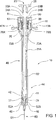
図1と図2を参照し、シリンジ10は、プランジャ20と、バレル40と、引き戻り式ニードル50とバネ式リテーナ60とを有する。バネ式リテーナ60は、バレル40の張り出し端部41内に配され、図1に示される初期圧縮状態にバネ90を収納、維持するよう協働する第1の本体部材70と第2の本体部材80とからなる。シリンジ10は、プランジャ20とバレル40の内壁42の間からの漏出流体を防止する、プランジャ20上に配されるシール11からもなる。
With reference to FIGS. 1 and 2, the
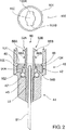
引き戻り式ニードル50は、バレル40のニードル端44に搭載され、カニューレ51と、シリンジ10の流体内容物の供給端で、ニードル50の引き戻しを容易にするため、プランジャ20内でニードル係合手段23の各返し係合アパーチャ22によって係合可能である、本体53に搭載された返し付きアーム52A、52Bとからなる。この引き戻しは、以下により詳細に説明されるように、バネ90の圧縮解除により推進される。
A
特に図2において、好適な実施例は、バレル40の内壁42上の環状リブ46と協働す
る窪み101を有するディスク部材100によって、引き戻りニードル50が、バレル40のニードル端44に取り付けられ得るとして説明されている。Oリングシール47が、バレル壁42内の環状段部48内に配される。引き戻りニードル50の本体53は、引き戻りニードル50の引き戻し動作まで、ディスク部材100の環状肩部104によって保持されるエルボ54A、54Bを有する。
With particular reference to FIG. 2, the preferred embodiment allows the
本実施例によると、返し付きアーム52A、52Bはそれぞれ、第1の返し55A、55Bと第2の返し56A、56Bとからなることも分かる。第1の返し55A、55Bは、第2の返し56A、56Bが、各返し係合アパーチャ22と正しく係合しなかった場合に、安全機構を提供し、引き戻りニードル50の後退を容易にする。すなわち、第1の返し55A、55Bは、第2の返し56A、56Bが各アパーチャ22と正しく係合し損なった場合に、返し係合アパーチャ22と係合できる。
According to the present embodiment, it can also be seen that the
以下により詳しく説明されるように、ディスク部材100は、ニードル50の後退を可能にするため、内部でエルボ54A、54Bの長手方向の移動を可能にする、凹部103A、103Bを備えたアパーチャ102を有する。
As will be described in more detail below, the
別の一実施例において、引き戻りニードル50が、オーストラリア特許第731159号と米国特許第6,083,199号に記載されるように提供され得る。
図3Aと3Bでもっともよく示されるように、プランジャ20は、それぞれが傾斜面34A、34Bを有する肩部33A、33Bを備えたプランジャシャフト32と、ユーザが操作できるボタン35とからさらになる。
In another embodiment, a
As best shown in FIGS. 3A and 3B, the
バレル40は、指用グリップ43A、43Bと、バネ式リテーナ60が取り付けられる張り出し端部41とが一体成形されている。
図3Aに示されるように、バネ式リテーナ60は、締まり嵌めなどによって、バレル40の張り出し端部41に嵌め込まれ得、それにより第1の本体部材70がバレル40の壁42に係合する。本実施例によると、第1の本体部材70は、壁42の各段部45A、45Bと係合するクリップ79A、79Bによって、バレル40内に保持される。
In the
As shown in FIG. 3A, the
プランジャ20の動作、特にプランジャ20の回転と、ニードル50の後退を容易にするため、引き戻り式ニードル返し52A、52Bとのニードル係合手段23の整列の理解は、図4Aと図4Bをここで参照することで得られる。
In order to facilitate the operation of the
プランジャ20は、第1のスロット24と、第2のスロット25と、後退スロット26と、第4のスロット27とを含む。第1のスロット24は、第1の偏向部28を介して第2のスロット25に相互接続されており、第2のスロット25は、第2の偏向部29を介して後退スロット26に相互接続されており、後退スロット26は、第3の偏向部30を介して第4のスロット27に相互接続されており、第4のスロット27は、第4の偏向部31を介して第1のスロット24に相互接続されている。図4Aと図4Bの矢印で示されるように、第1のスロット24と後退スロット26は、たがいに対して長手方向に補正されており、第2のスロット25と第4のスロット27はたがいに対して長手方向に補正されており、第1の偏向部28と第3の偏向部30は、たがいに対して長手方向に補正されており、第2の偏向部29と第4の偏向部31は、たがいに対して長手方向に補正されている。
第2のスロット25は、複数個の突き合わせ部21Aから成り、第1のスロット24は第1のスロット突き合わせ部21Bを含み、後退スロット26は後退突き合わせ部21C
とロックアウト突き合わせ部21Dとを含む。
The
And the
図4Aと4Bにおいて、本体71と、プランジャ20をスライド式に収容する第1のプランジャアパーチャ74と、たがいに長手方向に対面するように向けられた第1のフィンガまたは突起部73Aと第2のフィンガまたは突起部73Bとを有するカラー72とからなるバネ式リテーナ60の第1の本体部材70も図示される。第1の本体部材70は、本体71内に各タブ75A、75Bからさらになる。
4A and 4B, a
図4Aまたは図4Bに示されるように、使用時、第1のフィンガまたは突起部73Aと第2のフィンガまたは突起部73Bは、それぞれの対応するスロット24、25、26、または27と係合する。
As shown in FIG. 4A or 4B, in use, the first finger or
以下により詳細に説明するように、フィンガ73A、73Bは、国際公開第WO01/80930号に説明されるものと同様の様態にて、プランジャ20の再使用の防止を容易にするべく、プランジャ20のスロット内の突き合わせ部21A、21B、21Cとそれぞれ係合可能である。
As will be described in more detail below, the
別の一実施例において、突起部73A、73Bは球形またはほぼ球形で、かかる球形突起を受容するよう適切に構成されたスロットとスムーズにスライド式に係合できるようにできる。
In another embodiment, the
次に図5を参照するが、バネ式リテーナ60は、たがいに適合されたときに、バネ90を初期圧縮状態に維持するよう協働する第1の本体部材70と第2の本体部材80とからなる。
Referring now to FIG. 5, the
第2の本体部材80は、プランジャ20をスライド式に収容する第2のプランジャアパーチャ81からなる。第2の本体部材80は、肩傾斜82A、82Bと肩凹部83A、83Bとからもなる。第2の本体部材80の外壁84上には、一端に各ガイド86A、86Bを有し、他端に各スカラップ凹部87A、87Bを有する円周上の傾斜部85A、85Bもある。
The 2nd
第1の本体部材70と第2の本体部材80は、第1の本体部材70の各タブ75A、75Bを受容し、タブ75A、75Bがスカラップ凹部87A、87B内にそれぞれ適合するように、第2本体部材70に対して第2の本体部材80を回転させる、第2の本体部材80の側壁84内のガイド86A、86Bにより、バネ90を圧縮させるべく、プランジャ20上でたがいに嵌め合わされる。
The
バネ式リテーナ60を組み立てた場合、第2の本体部材80は、スカラップ凹部87A、87Bからタブ75A、75Bを係合解除させることなく、したがって、第1の本体部材70から第2の本体部材80を偶発的に係合解除させることなく、圧縮されたバネ90の作用に対抗して、第1の本体部材70に対する、限られた長手方向または入れ子動作が可能である。
When the
典型的に、この動作は、シリンジ、プランジャおよび/またはバネの長さおよび/または容量にしたがって容易に変動するが、0.1〜1.0mm、好適には約0.2〜0.8mmまたは優位には0.5mmに制限される。 Typically, this movement will vary easily according to the length and / or volume of the syringe, plunger and / or spring, but is 0.1-1.0 mm, preferably about 0.2-0.8 mm or The advantage is limited to 0.5 mm.
タブ75A、75Bとスカラップ凹部87A、87Bの間の係合は、第1の本体部材70に対する第2の本体部材80の回転を約5°以内に制限する。
シリンジ充填、注入およびニードル50の後退の間のプランジャ20の回転は図4Aと
図4Bと、国際公開第WO01/80930号も参照して最もよく理解され得る。
Engagement between
The rotation of the
初めに、使用中、第1の突起部73Aは第1のスロット24内に配され、第2の突起部73Bは後退スロット26内に配される。
プランジャ20の後退の後、第1の突起部73Aが、第1の偏向部28を介して、第1のスロット24から第2のスロット25内へスライド移動し、第2の突起部73Bが第3の偏向部30を介して、抗体スロット26から第4のスロット27内へ移動する。これにより、バレル50に対するプランジャ20の90°の回転が生じる。
Initially, in use, the
After the
プランジャ20の後退中、肩部33A、33Bは、第2の本体部材80の各肩凹部83A、83B内を自由にスライドして進む。
バレル40から物質を注入あるいは放出するためのプランジャ20の押し込みは、第1の突起部73Aが第2のスロット25内にスライド可能に配され、第2の突起部73Bが第4のスロット27内にスライド可能に配された場合に生じる。
While the
Pushing of the
したがって、この時点で、プランジャ20の返し係合アパーチャ22は、引き戻りニードル50の返し付きアーム52A、52Bと係合できるように整列される。
押し込み中、バネ90はバネ式リテーナ60により圧縮状態のままであり、プランジャ20の押し込みの最後に向かってのみ、バネ90の圧縮解除が生じる。
Thus, at this point, the return engagement aperture 22 of the
During pushing, the
第1の本体部材70からの第2の本体部材80係合解除の開始が図6に示され、ここで、バネ90をさらに圧縮するべく、第2の本体部材80を長手方向に移動させるため、本体プランジャ20の肩部33A、33Bの傾斜面34A、34Bが各肩傾斜部82A、82Bと係合する。これに伴い、返し係合アパーチャ22が引き戻りニードル50の返し部52A、52Bとそれぞれ係合し、それによって、プランジャ20を引き戻りニードル50に連結する。
The start of disengagement of the
プランジャ20の各肩部33A、33Bの傾斜面34A、34Bは、プランジャ20の押し込みの本当の最後で、第2の本体部材80内での肩傾斜部82A、82Bの「最後の瞬間の」係合のみを保証することに留意する。
The inclined surfaces 34A, 34B of each
第1の本体部材70に対する第2の本体部材80の長手移動は、第2のスロット25と係合する第1の突起部73Aと、プランジャ20の第4のスロット27と係合する第2の突起部73Bにより、それ自体は回転することが不可能なプランジャ20の直線移動によって推進される。プランジャ20の押し込み中にユーザによりプランジャに加えられる力は、各肩部33A、33Bの傾斜面34A、34Bと、第2の本体部材80内の肩傾斜部82A、82Bとの間の係合を介して、第2の本体部材80に伝達されるため、各タブ75A、75Bによるスカラップ凹部87A、87Bの係合を解放するに十分に、第1の本体部材70回転不可に対して第2の本体部材80を回転させる。この解放が、第1の本体部材70からの第2の本体部材80の係合解除を開始し、それによりバネ90が圧縮解除でき、次に、第2の本体部材80の円周上の傾斜部85A、85Bを、第1の部材70(回転不可)のタブ75A、75Bに対してスライドさせ、それにより、第1の本体部材70から係合解除する際に、第1の本体部材70に対して第2の本体部材80の回転を強制的に行う。この力は、プランジャ20の肩部33A、33Bに対して接している第2の本体部材80によりプランジャに中継され、それにより、プランジャ20と引き戻りニードル50の回転と後退を強制的に行う。
The longitudinal movement of the second
これは最後の90°のプランジャ回転で、第1の突起部73Aが第2の偏向部29を介して後退スロット26内に移動し、第2の突起部73Bが第4の偏向部31を介して、第4のスロット27から第1のスロット24内へ移動する。
This is the last 90 ° plunger rotation, and the
この時点で、また国際公開第WO01/80930号に記載されるものと同様の様態で、引き戻りニードル50と、それに連結されたプランジャ20が最終操作不能位置に後退され、それにより突起部73B、73Aが第1のスロット24の突き合わせ部21Bと後退スロット26の突き合わせ部21Dにそれぞれ係合し、引き戻りニードル50をバレル40内に後退させた後に、プランジャ20の押し込みまたはさらなる引き込みを防止する。
At this point, and in a manner similar to that described in International Publication No. WO 01/80930, the retracting
図7に図示される一実施例において、第2の本体部材80が第1の本体部材70から係合解除されると、第2の本体部材80は、圧縮解除されたバネ90によって推進され、プランジャ20とともに軸方向に進む。その結果、円周上の傾斜部85A、85Bが第1の本体部材70のタブ75A、75Bとそれぞれ係合し、第2の本体部材80を、矢印で示される方向に強制的に回転させ、プランジャ20の肩部33A、33Bと第2の本体部材80の肩傾斜部82A、82Bとの係合によって、次にプランジャ20を回転させるまで、第2の本体部材80が進む。
In one embodiment illustrated in FIG. 7, when the
第1の本体部材70の突起部73A、73Bを、第2の本体部材80の回転によって生じたプランジャ20の回転に連結される第2の偏向部29と第4の偏向部31にそれぞれ整列させることで、前述の最終操作不能位置へのプランジャ20の回転は、その結果、第2の本体部材80の回転によって支援される。
The
これは、プランジャ20が完全に回転できず、さらなるプランジャ20の動作を阻害し、その結果引き戻りニードル50が部分的にしか後退されないままとなる状況の可能性を最小限に抑える。
This minimizes the possibility of a situation in which the
図7に図示される第2の本体部材80の本実施例は、延長首部88を有し、肩傾斜部82A、82Bが、たとえば図4や図5に図示される実施例と比較して、第2の本体部材80内へ多少引っ込んでいることも明白である。これは、第2本体部材80内にこれを効果的に「埋め込む」ことで、ユーザによるプランジャ20と第2の本体部材80の係合状態の変更の防止を支援する。
This embodiment of the
また、プランジャ20の肩部33A、33Bと係合し、第2本体部材80に対してユーザがプランジャ20を強制的に回転させることを防止するリブ89A、89Bもある。
十分な長さ(プランジャシャフト21にそった長手方向に)を有するプランジャ肩部33A、33Bにより、突起部73A、73Bが、プランジャ20の後退の開始時に後退スロット26と第1のスロット24のそれぞれにまだ係合していないときに、プランジャ20の回転を防止できることも分かる。これは、後退が開始する前に、ユーザがプランジャ20を操作位置に戻そうとすることを防止する支援をする。
There are also
Plunger shoulders 33A, 33B having a sufficient length (in the longitudinal direction along the plunger shaft 21) allow the
したがって、以上の説明から、圧縮解除されたバネ90が、プランジャ20と引き戻りニードル50の後退を容易にするよう作用するのは、プランジャ20の押し込みの本当の最後のみであることが明白となる。これは、注入のほとんどの段階中にいかなる著しいバネ90抵抗が感じられることなく、シリンジの操作にはるかにスムーズな感触を与える。
Thus, it will be clear from the above description that the
本発明のバネ式リテーナ60によって提供される別の利点は、さまざまなニードルサイズとシリンジサイズと操作可能であるのと同様、さまざまなサイズのバネ90を収容できる点にある。長めのニードルを備えたより高容量のシリンジの場合、プランジャ20の引き戻しを容易にするために必要なバネ90の長さは大きすぎて、バレル40の外側でプランジャ20に容易に適合できない。バネ式リテーナ60は、バネ90の非圧縮長さにかかわらず、バネ90を扱いやすいサイズまで圧縮する。
Another advantage provided by the
本明細書において、その目的は、いかなる一実施例または特定の特徴の集合に本発明を限定することなく、本発明の好適な実施例を記載することにあった。本発明から逸脱することなく、説明、図示される実施例に種々の変更と改変が行える。 In the present specification, the aim was to describe a preferred embodiment of the invention without limiting the invention to any one embodiment or specific collection of features. Various changes and modifications may be made to the embodiments described and illustrated without departing from the invention.
たとえば、第2の本体部材80と係合するプランジャ手段と、第2の本体部材80上の各相補係合部分は、本願に説明されるように肩部33A、33Bと肩傾斜部82A、82Bに制限されない、いかなる適切な構成でもよい。
For example, the plunger means that engages the
これに加え、タブ75A、75Aとスカラップ凹部87A、87Bは、該第1の本体部材70と第2の本体部材80を解放可能に連結する手段の例であるが、本発明は、該ハウジングを形成し、それによってバネ90を初期圧縮状態に維持するため、該第1の本体部材70と第2の本体部材80の解放可能な連結を容易にするべく、第1の本体部材70と第2の本体部材80上の相補係合部を利用するいかなる他の構成も企図する。
In addition, the
本発明は、円周上の傾斜部85A、85Bが、第2の本体部材80と、それと係合したプランジャ20の強制回転なしに、第1の本体部材70と第2の本体部材80の係合解除中に長手方向にタブ75A、75Bを移動させる、各チャンネルかガイドスロットに取り替えられた別の実施例を企図することも明らかである。
In the present invention, the
本願に記載される、突き合わせ部21A、21B、21Cおび21Dは、熟練者によって望まれるプランジャ動作を制限する出っ張り、ゲート、うねあるいはその他のいかなる段であってもよい。
The
Claims (20)
からなるバネ式リテーナ。A spring retainer for a syringe comprising a barrel, a plunger, a spring, and a retracting needle connectable to the plunger to allow retraction into the barrel, the spring retainer comprising a first and a first retainer The first and second body members rotate relative to each other to facilitate retraction of the retracting needle and the plunger connected thereto into the barrel. engagement is released, until allowing the decompression of the spring, spring retainer comprising a that is adapted to releasably maintain the spring in a compressed state.
からなるシリンジ。A syringe comprising a barrel, a plunger, a spring type retainer, and a spring, and the syringe is provided with a retracting needle so that it can be connected to the plunger for the retraction of the needle into the barrel. The spring retainer comprises a housing having first and second body members to facilitate retraction of the retracting needle and a plunger coupled thereto into the barrel. A syringe comprising: disengaging the first and second body members to releasably maintain the spring in a compressed state until the spring can be decompressed.
Applications Claiming Priority (3)
| Application Number | Priority Date | Filing Date | Title |
|---|---|---|---|
| AU2003901301A AU2003901301A0 (en) | 2003-03-20 | 2003-03-20 | Syringe spring retainer |
| AU2003905080A AU2003905080A0 (en) | 2003-09-18 | Syringe spring retainer II | |
| PCT/AU2004/000354 WO2004082747A1 (en) | 2003-03-20 | 2004-03-19 | Syringe spring retainer |
Publications (3)
| Publication Number | Publication Date |
|---|---|
| JP2006520219A JP2006520219A (en) | 2006-09-07 |
| JP2006520219A5 JP2006520219A5 (en) | 2007-04-19 |
| JP4652326B2 true JP4652326B2 (en) | 2011-03-16 |
Family
ID=33030374
Family Applications (1)
| Application Number | Title | Priority Date | Filing Date |
|---|---|---|---|
| JP2006503971A Expired - Fee Related JP4652326B2 (en) | 2003-03-20 | 2004-03-19 | Spring retainer for syringe |
Country Status (16)
| Country | Link |
|---|---|
| US (1) | US8021333B2 (en) |
| EP (2) | EP2596824B1 (en) |
| JP (1) | JP4652326B2 (en) |
| AR (1) | AR043668A1 (en) |
| CA (1) | CA2518360C (en) |
| CL (1) | CL2004000581A1 (en) |
| DK (1) | DK1608421T3 (en) |
| ES (1) | ES2424947T3 (en) |
| HK (1) | HK1090859A1 (en) |
| MX (1) | MXPA05009932A (en) |
| MY (1) | MY141268A (en) |
| NZ (1) | NZ542635A (en) |
| PE (1) | PE20050098A1 (en) |
| PT (1) | PT1608421E (en) |
| TW (1) | TWI253944B (en) |
| WO (1) | WO2004082747A1 (en) |
Families Citing this family (68)
| Publication number | Priority date | Publication date | Assignee | Title |
|---|---|---|---|---|
| WO2005070292A1 (en) | 2004-01-23 | 2005-08-04 | Medigard Limited | Improvements to a blood collection device |
| US8002745B2 (en) * | 2004-01-28 | 2011-08-23 | Unitract Syringe Pty Ltd. | Retractable syringe with plunger disabling system |
| PL2455125T3 (en) | 2004-09-03 | 2018-05-30 | L.O.M. Laboratories Inc. | Single-use pneumatic safety syringe with retractable needle |
| US11590286B2 (en) | 2004-11-22 | 2023-02-28 | Kaleo, Inc. | Devices, systems and methods for medicament delivery |
| US7648482B2 (en) | 2004-11-22 | 2010-01-19 | Intelliject, Inc. | Devices, systems, and methods for medicament delivery |
| US10737028B2 (en) | 2004-11-22 | 2020-08-11 | Kaleo, Inc. | Devices, systems and methods for medicament delivery |
| US7648483B2 (en) | 2004-11-22 | 2010-01-19 | Intelliject, Inc. | Devices, systems and methods for medicament delivery |
| US7416540B2 (en) | 2004-11-22 | 2008-08-26 | Intelliject, Llc | Devices systems and methods for medicament delivery |
| US7947017B2 (en) | 2004-11-22 | 2011-05-24 | Intelliject, Inc. | Devices, systems and methods for medicament delivery |
| AU2006210865B2 (en) | 2005-02-01 | 2008-12-04 | Kaleo, Inc. | Devices, systems, and methods for medicament delivery |
| TWI265036B (en) * | 2005-04-29 | 2006-11-01 | Guo-Ming Huang | Safety injector and method of operating the same |
| US10058656B2 (en) | 2006-10-24 | 2018-08-28 | Pmt Partners, Llc | Syringe with rotatable element, systems including the syringe, and associated methods |
| US8672893B2 (en) * | 2007-10-23 | 2014-03-18 | Control Medical Technology, Llc | Syringe with rotatable element, aspiration systems including the syringe, and associated methods |
| NZ595031A (en) | 2007-07-02 | 2012-02-24 | Unitract Syringe Pty Ltd | Automatically retracting syringe with spring based mechanisim |
| US9381309B2 (en) | 2008-06-10 | 2016-07-05 | Retractable Technologies, Inc. | Frontal attachment device for syringe with pinch-activated retraction |
| US9308353B2 (en) | 2010-07-29 | 2016-04-12 | Retractable Technologies, Inc. | Needle retraction apparatus |
| US20090306601A1 (en) | 2008-06-10 | 2009-12-10 | Shaw Thomas J | Fluid Flow Control Device with Retractable Cannula |
| US8496600B2 (en) * | 2008-06-10 | 2013-07-30 | Retractable Technologies, Inc. | Non-reusable collection device for bodily fluids |
| US9480799B2 (en) * | 2009-04-08 | 2016-11-01 | Stat Medical Devices, Inc. | Retractable needle assembly utilizing a standard interface and syringe utilizing the same |
| US8986249B2 (en) * | 2009-04-08 | 2015-03-24 | Stat Medical Devices, Inc. | Retractable needle assembly and syringe utilizing the same |
| US20110125130A1 (en) * | 2009-04-08 | 2011-05-26 | Stat Medical Devices, Inc. | Retractable needle assembly and syringe utilizing the same |
| NZ596905A (en) | 2009-06-17 | 2012-12-21 | Unitract Syringe Pty Ltd | Adaptor for a retractable syringe which removably mounts to the barrel of a syringe, wherein a sealing member in the adaptor is penetrable by a needle of the syringe |
| CN102791312B (en) * | 2009-12-22 | 2015-09-30 | 尤尼特拉克特注射器公司 | There is the delivery efficiency of improvement and the retraction formula syringe of locking system |
| CA2797207C (en) * | 2010-05-04 | 2018-08-14 | Unitract Syringe Pty Ltd | Syringe barrel adapter and needle assembly |
| US9084849B2 (en) | 2011-01-26 | 2015-07-21 | Kaleo, Inc. | Medicament delivery devices for administration of a medicament within a prefilled syringe |
| US8627816B2 (en) | 2011-02-28 | 2014-01-14 | Intelliject, Inc. | Medicament delivery device for administration of opioid antagonists including formulations for naloxone |
| US8939943B2 (en) | 2011-01-26 | 2015-01-27 | Kaleo, Inc. | Medicament delivery device for administration of opioid antagonists including formulations for naloxone |
| PT2739328T (en) * | 2011-08-05 | 2018-06-29 | Unl Holdings Llc | Dual chamber mixing device for a syringe |
| AU2012298793B2 (en) | 2011-08-24 | 2016-07-07 | Unitract Syringe Pty Ltd | Auto-injector for retractable prefilled syringe |
| US9821118B2 (en) | 2011-09-02 | 2017-11-21 | Unl Holdings Llc | Automatic reconstitution for dual chamber syringe |
| CA3080331C (en) | 2011-10-14 | 2023-06-06 | Amgen Inc. | Injector and method of assembly |
| US9078978B2 (en) | 2011-12-28 | 2015-07-14 | Stat Medical Devices, Inc. | Needle assembly with safety system for a syringe or fluid sampling device and method of making and using the same |
| CA2862880C (en) | 2012-02-06 | 2020-04-07 | Unitract Syringe Pty Ltd | Plunger sub-assemblies and auto-injectors having low retraction activation force |
| US9522235B2 (en) | 2012-05-22 | 2016-12-20 | Kaleo, Inc. | Devices and methods for delivering medicaments from a multi-chamber container |
| EP2869871B1 (en) | 2012-07-05 | 2021-03-17 | UNL Holdings LLC | Automatic injectors for injectable cartridges and drive control mechanisms therefor |
| AU2013366011A1 (en) | 2012-11-09 | 2015-05-28 | Iinjec Technologies Inc. | Fluid delivery device and method |
| EP2925391B1 (en) | 2012-11-30 | 2017-05-03 | Unitract Syringe Pty Ltd | Combination plunger device for a dual chamber mixing syringe |
| USD829891S1 (en) | 2012-12-14 | 2018-10-02 | Retractable Technologies, Inc. | Syringe with offset needle retraction chamber and frontal attachment |
| US10568554B2 (en) | 2012-12-14 | 2020-02-25 | Retractable Technologies, Inc. | Blood collection tube holder with slide-activated needle retraction |
| USD823461S1 (en) | 2012-12-14 | 2018-07-17 | Retractable Technologies, Inc. | Slimline syringe with offset needle retraction chamber and frontal attachment |
| US9302055B2 (en) | 2012-12-14 | 2016-04-05 | Retractable Technologies, Inc. | Frontal attachment device for syringe with rotationally activated retractable needle |
| USD823463S1 (en) | 2012-12-14 | 2018-07-17 | Retractable Technologies, Inc. | Frontal attachment for medical device |
| USD823457S1 (en) | 2012-12-14 | 2018-07-17 | Retractable Technologies, Inc. | Blood collection tube holder with offset needle retraction chamber and frontal attachment |
| US9956352B2 (en) | 2012-12-14 | 2018-05-01 | Retractable Technologies, Inc. | Combined medical device with sliding frontal attachment and retractable needle |
| ES2853748T3 (en) | 2013-03-22 | 2021-09-17 | Amgen Inc | Injector and mounting method |
| DK2991705T3 (en) | 2013-05-01 | 2020-02-03 | Unl Holdings Llc | STAMP DRIVE CAR INJECTORS |
| PT3003437T (en) | 2013-06-04 | 2019-10-28 | Unl Holdings Llc | Actuation mechanisms for dual chamber mixing syringes |
| JP6446042B2 (en) | 2013-07-01 | 2018-12-26 | クレデンス メドシステムズ インコーポレイテッド | Safety syringe |
| USD764657S1 (en) | 2013-07-03 | 2016-08-23 | Unitract Syringe Pty Ltd | Automatic injector |
| JP5684346B2 (en) * | 2013-08-26 | 2015-03-11 | ファナック株式会社 | Electric discharge machine with rotating shaft |
| US11097055B2 (en) * | 2013-10-24 | 2021-08-24 | Amgen Inc. | Injector and method of assembly |
| JP6559667B2 (en) | 2013-11-15 | 2019-08-14 | クレデンス メドシステムズ インコーポレイテッド | System and method for drug delivery using a safety syringe |
| WO2015117135A1 (en) | 2014-02-03 | 2015-08-06 | Unitract Syringe Pty Ltd | Selectable needle syringe with retraction plunger |
| EP3868427A1 (en) * | 2014-04-24 | 2021-08-25 | Credence Medsystems Inc. | System and method for safety syringe |
| US9517307B2 (en) | 2014-07-18 | 2016-12-13 | Kaleo, Inc. | Devices and methods for delivering opioid antagonists including formulations for naloxone |
| ES2834023T3 (en) | 2014-08-28 | 2021-06-16 | Unl Holdings Llc | Sensor systems for drug delivery devices |
| EP3185934B1 (en) | 2014-08-28 | 2018-06-20 | UNL Holdings LLC | Skin sensors for drug delivery devices |
| US10987469B2 (en) | 2014-09-25 | 2021-04-27 | Pmt Partners, Llc | Rotatable finger loop for syringe, syringe configured to receive the rotatable finger loop and associated methods |
| TWI681792B (en) | 2014-10-31 | 2020-01-11 | 加拿大商L O M 實驗股份有限公司 | Retractable needle syringe |
| BR112017011213A2 (en) | 2014-12-23 | 2018-02-14 | Automed Pty Ltd | delivery apparatus, system and associated methods |
| US10709847B2 (en) | 2015-01-20 | 2020-07-14 | L.O.M. Laboratories Inc. | Retractable needle syringe with unitary propellant release module |
| AU2016235054B2 (en) | 2015-03-24 | 2020-07-16 | Kaleo, Inc. | Devices and methods for delivering a lyophilized medicament |
| JP6830067B2 (en) | 2015-06-30 | 2021-02-17 | カレオ,インコーポレイテッド | Automatic syringe that administers medication in a prefilled syringe |
| WO2018119218A1 (en) | 2016-12-23 | 2018-06-28 | Kaleo, Inc. | Medicament delivery device and methods for delivering drugs to infants and children |
| EP3661442A4 (en) | 2017-08-03 | 2021-06-23 | Dfine, Inc. | Cement mixing and injection system and methods |
| CA3145580A1 (en) | 2019-08-09 | 2021-02-18 | Kaleo, Inc. | Devices and methods for delivery of substances within a prefilled syringe |
| US11957542B2 (en) | 2020-04-30 | 2024-04-16 | Automed Patent Holdco, Llc | Sensing complete injection for animal injection device |
| WO2024036031A1 (en) * | 2022-08-11 | 2024-02-15 | Paul Madan | Syringe with handle |
Citations (3)
| Publication number | Priority date | Publication date | Assignee | Title |
|---|---|---|---|---|
| US5112316A (en) * | 1988-06-23 | 1992-05-12 | Aldo Venturini | Disposable safety syringe |
| US5324265A (en) * | 1993-10-20 | 1994-06-28 | Gabbard Murray Gabbard Inc. | Hypodermic safety syringe with retracting needle system |
| WO2001080930A1 (en) * | 2000-04-26 | 2001-11-01 | Unitract Pty Ltd | Single use syringe |
Family Cites Families (23)
| Publication number | Priority date | Publication date | Assignee | Title |
|---|---|---|---|---|
| US5222947A (en) * | 1990-04-18 | 1993-06-29 | Amico Elio D | Self recapping injection needle assembly |
| US5167641A (en) * | 1991-05-29 | 1992-12-01 | Arnis, Inc. | Auto-retracting needle injector system |
| WO1993012830A1 (en) | 1992-01-03 | 1993-07-08 | Lok-Needle Syringe Company Pty. Ltd. | Hypodermic syringe with retractable needle |
| ITMI920710A1 (en) | 1992-03-25 | 1993-09-27 | Federico Demetrio | SAFETY SYRINGE WITH RETRACTABLE NEEDLE AFTER USE SO AS TO AVOID REUSE OF THE SYRINGE AND THE SPREAD OF CONTAGIOUS DISEASES FOR |
| US5201720A (en) * | 1992-04-21 | 1993-04-13 | Joseph Borgia | Syringe holding and ejecting assembly |
| US5180370A (en) * | 1992-05-18 | 1993-01-19 | Gillespie Elgene R | Safety hypodermic syringe with retractable needle |
| ATE164771T1 (en) * | 1992-06-15 | 1998-04-15 | Adventec Inc | NEEDLE PROTECTED SYRINGE |
| US5411487A (en) * | 1992-12-07 | 1995-05-02 | Castagna; John F. | Hypodermic syringe with automatic needle cover |
| US5533970A (en) * | 1994-09-28 | 1996-07-09 | Becton, Dickinson And Company | Retractable needle syringe |
| US6090077A (en) * | 1995-05-11 | 2000-07-18 | Shaw; Thomas J. | Syringe plunger assembly and barrel |
| US5762634A (en) * | 1995-08-14 | 1998-06-09 | Vista Medical Innovations, Inc. | Protractable and retractable hypodermic needle syringe |
| US6569115B1 (en) * | 1997-08-28 | 2003-05-27 | Mdc Investment Holdings, Inc. | Pre-filled retractable needle injection device |
| US6039713A (en) * | 1997-08-28 | 2000-03-21 | Mdc Investment Holdings, Inc. | Pre-filled retractable needle injection device |
| AUPO940697A0 (en) | 1997-09-23 | 1997-10-16 | Kaal, Joseph Hermes | Retractable syringe |
| US6221052B1 (en) * | 1998-12-18 | 2001-04-24 | Becton, Dickinson And Company | Retracting needle syringe |
| US5984898A (en) * | 1999-02-17 | 1999-11-16 | Retrax Safety Systems Inc. | Retractable needle and syringe combination |
| FR2794650B1 (en) * | 1999-06-10 | 2001-09-14 | Marc Brunel | SINGLE USE INJECTION DEVICE |
| FR2799976B1 (en) * | 1999-10-26 | 2002-06-21 | Plastic Omnium Cie | SAFETY DEVICE FOR INJECTION SYRINGE |
| US6558357B1 (en) | 2000-08-30 | 2003-05-06 | Becton Dickinson And Company | Hypodermic syringe with selectively retractable needle |
| EP1232763A1 (en) * | 2001-02-14 | 2002-08-21 | Sergio Restelli | Disposable syringe |
| US7033343B2 (en) * | 2001-03-15 | 2006-04-25 | Mdc Investment Holdings, Inc. | Retractable needle medical device for injecting fluid from a pre-filled cartridge |
| EP1273316A1 (en) * | 2001-07-02 | 2003-01-08 | Sergio Restelli | Disposable safety syringe |
| US6527742B1 (en) * | 2001-11-14 | 2003-03-04 | Robert C. Malenchek | Safety syringe |
-
2004
- 2004-03-19 CL CL200400581A patent/CL2004000581A1/en unknown
- 2004-03-19 JP JP2006503971A patent/JP4652326B2/en not_active Expired - Fee Related
- 2004-03-19 PE PE2004000288A patent/PE20050098A1/en active IP Right Grant
- 2004-03-19 MX MXPA05009932A patent/MXPA05009932A/en active IP Right Grant
- 2004-03-19 EP EP13156459.3A patent/EP2596824B1/en not_active Expired - Lifetime
- 2004-03-19 NZ NZ542635A patent/NZ542635A/en not_active IP Right Cessation
- 2004-03-19 ES ES04721775T patent/ES2424947T3/en not_active Expired - Lifetime
- 2004-03-19 AR ARP040100931A patent/AR043668A1/en not_active Application Discontinuation
- 2004-03-19 DK DK04721775.7T patent/DK1608421T3/en active
- 2004-03-19 PT PT47217757T patent/PT1608421E/en unknown
- 2004-03-19 CA CA2518360A patent/CA2518360C/en not_active Expired - Fee Related
- 2004-03-19 EP EP04721775.7A patent/EP1608421B1/en not_active Expired - Lifetime
- 2004-03-19 TW TW093107403A patent/TWI253944B/en not_active IP Right Cessation
- 2004-03-19 MY MYPI20040978A patent/MY141268A/en unknown
- 2004-03-19 WO PCT/AU2004/000354 patent/WO2004082747A1/en active Application Filing
- 2004-03-19 US US10/549,710 patent/US8021333B2/en active Active
-
2006
- 2006-10-19 HK HK06111515.7A patent/HK1090859A1/en not_active IP Right Cessation
Patent Citations (3)
| Publication number | Priority date | Publication date | Assignee | Title |
|---|---|---|---|---|
| US5112316A (en) * | 1988-06-23 | 1992-05-12 | Aldo Venturini | Disposable safety syringe |
| US5324265A (en) * | 1993-10-20 | 1994-06-28 | Gabbard Murray Gabbard Inc. | Hypodermic safety syringe with retracting needle system |
| WO2001080930A1 (en) * | 2000-04-26 | 2001-11-01 | Unitract Pty Ltd | Single use syringe |
Also Published As
| Publication number | Publication date |
|---|---|
| EP1608421A4 (en) | 2011-11-09 |
| DK1608421T3 (en) | 2013-07-01 |
| MXPA05009932A (en) | 2006-03-21 |
| CL2004000581A1 (en) | 2005-01-21 |
| EP2596824B1 (en) | 2017-04-19 |
| US20060235354A1 (en) | 2006-10-19 |
| TWI253944B (en) | 2006-05-01 |
| AR043668A1 (en) | 2005-08-03 |
| WO2004082747A1 (en) | 2004-09-30 |
| NZ542635A (en) | 2006-10-27 |
| ES2424947T3 (en) | 2013-10-10 |
| PT1608421E (en) | 2013-07-26 |
| PE20050098A1 (en) | 2005-05-11 |
| TW200418543A (en) | 2004-10-01 |
| EP1608421A1 (en) | 2005-12-28 |
| CA2518360A1 (en) | 2004-09-30 |
| CA2518360C (en) | 2011-12-20 |
| EP1608421B1 (en) | 2013-05-15 |
| HK1090859A1 (en) | 2007-01-05 |
| MY141268A (en) | 2010-04-16 |
| US8021333B2 (en) | 2011-09-20 |
| JP2006520219A (en) | 2006-09-07 |
| EP2596824A1 (en) | 2013-05-29 |
Similar Documents
| Publication | Publication Date | Title |
|---|---|---|
| JP4652326B2 (en) | Spring retainer for syringe | |
| US11087640B2 (en) | Medicament delivery training device | |
| US8002745B2 (en) | Retractable syringe with plunger disabling system | |
| US6494863B1 (en) | One-use retracting syringe with positive needle retention | |
| US9044553B2 (en) | Apparatus for injecting a pharmaceutical with automatic syringe retraction following injection | |
| ES2349667T3 (en) | AUTOMATIC INJECTORS | |
| JP5074397B2 (en) | Grip ring for use with needle cover assembly and needle tip assembly | |
| JP4533143B2 (en) | Disposable syringe and plunger rod locking device for the syringe | |
| TW201247266A (en) | Auto-injector | |
| CN105592874B (en) | Medicament delivery device | |
| JPH07503384A (en) | automatic syringe | |
| JPH10113388A (en) | Injection device | |
| JP2004537390A (en) | Safety syringe | |
| JP7178102B2 (en) | safety syringe | |
| TW202026022A (en) | Injection device with commit feature | |
| JP2004535265A (en) | Single use syringe | |
| JP2008142565A (en) | Single-use retractable syringe equipped with positive needle holding | |
| AU2004222676B2 (en) | Syringe spring retainer | |
| ZA200508400B (en) | Syringe spring retainer | |
| TWI242457B (en) | Retractable type safety syringe structure | |
| TW467752B (en) | Safety injection needle cylinder structure |
Legal Events
| Date | Code | Title | Description |
|---|---|---|---|
| A521 | Written amendment |
Free format text: JAPANESE INTERMEDIATE CODE: A523 Effective date: 20070302 |
|
| A621 | Written request for application examination |
Free format text: JAPANESE INTERMEDIATE CODE: A621 Effective date: 20070302 |
|
| A131 | Notification of reasons for refusal |
Free format text: JAPANESE INTERMEDIATE CODE: A131 Effective date: 20090901 |
|
| A521 | Written amendment |
Free format text: JAPANESE INTERMEDIATE CODE: A523 Effective date: 20091127 |
|
| A131 | Notification of reasons for refusal |
Free format text: JAPANESE INTERMEDIATE CODE: A131 Effective date: 20100323 |
|
| A521 | Written amendment |
Free format text: JAPANESE INTERMEDIATE CODE: A523 Effective date: 20100609 |
|
| TRDD | Decision of grant or rejection written | ||
| A01 | Written decision to grant a patent or to grant a registration (utility model) |
Free format text: JAPANESE INTERMEDIATE CODE: A01 Effective date: 20101207 |
|
| A01 | Written decision to grant a patent or to grant a registration (utility model) |
Free format text: JAPANESE INTERMEDIATE CODE: A01 |
|
| A61 | First payment of annual fees (during grant procedure) |
Free format text: JAPANESE INTERMEDIATE CODE: A61 Effective date: 20101215 |
|
| R150 | Certificate of patent or registration of utility model |
Ref document number: 4652326 Country of ref document: JP Free format text: JAPANESE INTERMEDIATE CODE: R150 Free format text: JAPANESE INTERMEDIATE CODE: R150 |
|
| FPAY | Renewal fee payment (event date is renewal date of database) |
Free format text: PAYMENT UNTIL: 20131224 Year of fee payment: 3 |
|
| R250 | Receipt of annual fees |
Free format text: JAPANESE INTERMEDIATE CODE: R250 |
|
| R250 | Receipt of annual fees |
Free format text: JAPANESE INTERMEDIATE CODE: R250 |
|
| R250 | Receipt of annual fees |
Free format text: JAPANESE INTERMEDIATE CODE: R250 |
|
| R250 | Receipt of annual fees |
Free format text: JAPANESE INTERMEDIATE CODE: R250 |
|
| R250 | Receipt of annual fees |
Free format text: JAPANESE INTERMEDIATE CODE: R250 |
|
| R250 | Receipt of annual fees |
Free format text: JAPANESE INTERMEDIATE CODE: R250 |
|
| R250 | Receipt of annual fees |
Free format text: JAPANESE INTERMEDIATE CODE: R250 |
|
| LAPS | Cancellation because of no payment of annual fees |